student examination attendance system via radio frequency identification (rfid) simulator
DESCRIPTION
dono la...TRANSCRIPT
STUDENT EXAMINATION ATITINDANCE SYSTEM VIA RADIO-
FREQUENCY IDENTIFICATION (RFID) SIMULATOR
MOHD HAIKAL B MOHD BAHARUDIN
This report is submitted in partial fulfillment of the requirements for the
Bachelor of Computer Science (Computer Networking)
FACULTY OF INFORMATION AND COMMUNICATION TECHNOLOGY
UNIVERSITI TEKNIKAL MALAYSIA MELAKA
2007
ABSTRACT
RAFIDASOl is a code name for the Radio-Frequency Examination Attendance System for this project. The main reason for RAFIDASOl is replace the manual technique for the attendance data collection for the examination candidates. In the manual system, the process use paper-based form to ensure whether the students present or absent during the examination. These forms will then be collected by the examination officer. RAFIDASOl is a digital system that combines the web-based system, database, and the RFID technique as the main structure of the system. RHD will detect all the RFID tags that will embedded on the student candidate)'^ metric card. Finally, examination officer only need to access the system to retrieve the final result of the examination attendance.
ABSTRAK
RAFlDASOl adalah kod nama bagi Sistem Kehadiran Peperiksaan Menggunakan Pengesanan Radio-frequensi dalam projek ini. Tujuan utama system ini adalah untuk menggantikan teknik manual bagi proses pengambilan data kedatangan calon-calon peperiksaan. Dalm teknik manual, proses ini akan menggunakan cara berasaskan borang kertas untuk menilai kehadiran dan ketidakhadiran dalam peperiksaan. Borang tersebut akan dikumpul oleh pengawas peperiksaan. RAFIDASOl adalah sebuah sistem digital yang menggabungkan aplikasi berteraskan-web , pangakalan data, dan teknik pengesanan Radio-fiequensi (RFID) sebagai struktur utama sistem. RFID akan mengesan mikrocip yang terselit di atas kad matrik calon-calon dari jarak jauh. Di akhir keputusan, pengawas peperiksaan hanya perlu menggunakan sistern ini untuk menganbil keputusan keseluruhan kedatangan bagi satu peperiksaan.
INTRODUCTION
1.1 Project Background
Radio-Frequency identification (RFTD) is an automatic identification method,
relying on storing and remotely retrieving data using devices called RFID tags or
transponders. An RFID tag is an object that can be attached to or incorporated into a
product, animal, or person for the purpose of identification using radio waves. All RFID
tags contain at least two parts. The first part is an integrated circuit (microchip) for
storing and processing information, modulating and demodulating a radio frequency (RF)
signal and perhaps other specialized functions. Second part is an antenna for transmitting
and receiving the signal.
The examination attendance system is a web based system that will process the
data given by the information from the microchip that contains the candidate information.
The system that uses a PHP Script also holds all the data of each student, and then it will
compare with the data that it captures using the RFID. If the comparing process shows a
different, it means that some candidate might absent for the exam.
The type of RFID that will be use inside this project is-a passive RFID. The
passive RFID tags have no internal power supply. The antenna will transmit the signal to

the microchip that will embed on the candidate metric card, and then the microchip will
rebound the signal back to the antenna. The antenna might be situated at the entrance of
the examination hall.
The code name for the prototype of the system is RAFIDASOl.
1.2 Problem Statement
There are some problem occurs during the normal technique of collecting the data
for the present examination candidates. The major problem is the technical problems.
The technical problem is there is no digital system that can evaluate the presence
or absence of the candidates during the examination process. To overcome the problem,
one system that can evaluate the presence or absence of students needs to be developed.
In addition, during the technical process of collecting data, the data are exposed to
a human technical error. For example, data might be missing during the filling out
process, attendance form might missing during the collecting process and the data has to
be arrange according to the candidate's faculty or matrix number.
The attendance of the examination candidates is very important to prove that the
candidate has taken the exam. The system is also needed to ensure the accuracy of the
data that it will collect.
1.3 Project Objective
The main project objective is:
To create an RFID Simulator
To create a webbased system which will integrate with RFID Simulator
The system will use Radio-Frequency Identification (RFID) Simulator as
the main input to collect candidate's attendance during the examination
The system also able to compare the data that it has collected during the
examination hour and the existing data inside the database
The system also should able to display the result of the attendance
1.4 Project Scope
The scopes of the project are:
To develop an RFID simulator using the PHP script to simulate the
process of RFID
TO develop a web-based system using a PHP scripting which is the script
will be type using the Macromedia Dreamweaver MX 2004.
The existing data will be stored inside one database which is a MySQL
database as the database server. The database will have dummy data which
will simulate the Student Information System (SMP) data.
Then, after the data has successfully compared, the details of present and
the absent'examination candidates will be displayed as the final result and
the system also will provide the brief statistic of the examination
candidates. Next, the statistic of the result will be able to print out fiom the
system.
1.5 Project Significance
This system should be able to overcome the technical human error during
collecting database candidate attendance and to create a centralized candidate attendance
data inside a database system. Besides, the system also helps user to use paperless
environment and save the candidate's times for filling the examination attendance form.
1.6 Expected Output
Based on the first planning, the expected result is to make sure all the result that
the system give are 100% true because the information of the attendance for the
examination candidates is a very high priority, important, and abstruse. Beside, the
system should replace the manual process for collecting the candidate attendance to avoid
the existing problems.
1.7 Conclusion
Developing RAmDASOl is a step further to enhance from the technical technique
to automatic technique when collecting the important data during the examination. The
important data is the attendance for the examination candidates. RAFIDASOl is a web
based system that will communicate with the RFID module for the main device to collect
the candidate's attendance. RAmDASOl also will give the result for the student who are
present or absent student during the examination. Using the Radio-Frequency, the RFID
module can capture candidate's data from the client microchip which is embedded on the
candidate matric card.
The next activity is to collect the project data requirement such as the literature
review, project methodology, hardware and software requirement. This data will help the ...
project development process and analysis.
CHAPTER I1
LITERATURE REVIEW AND PROJECT METHODOLOGY
2.1 Introduction
Literature review is a process to find, search, collect, analyze and concluded all
debates and issues raised for developing the final product of the project. Besides, it also
provide examples of what other experts have or reseaxher has found in the last time and
that idea could be a benefit for the next development process. That information will use
to overcome the current problems and try to investigate the solution to give the best
result for the project. The literature reviews are focuses on the various theory and basic
network knowledge used in the project. The sources of the information are able to grab
from the books, magazine, articles, web pages, or testing result. Project methodology
will discuss detail about type of methodology, techniques, hardware or software - b :
requirements and project planning to develop the project, so that the planning for the
project proposed to meet project objectives, scopes and requirements.
2.2 Fact and Finding
.*
There is lot of techniques used to gather information that related to the project
through Internet, book etc. These initial documents will provide some valuable
information to determine the basic view for the project. The theory and concept from the
past research, references, case study and other can be applied in order to understand the
thesis.
2.2.1 Domain
The domain for this project is ICT in Network Application. RFID module is one of
network tools and the system that will communicate the RFID module will generate a
network appIication.
2.2.1.1 History RFID
According to Landt J. (2001), "In 1906, the first continuous wave (CW) radio
generation and transmission of radio signals has demonstrated by Ernst F.W.
Alexanderson. The work in radar during World War I1 was as significant a technical
development as the Manhattan Project. Radar sends out radio waves for detecting and
locating an object by the reflection of the radio waves. This reflection can determine the . .
position and speed of an object. Radar's significance was quickly understood by the
military, so many of the early developments are very secret." This straightly shows that
the RFID technology has been develop around 1900's. Since one form of RFID is the
combination of radio broadcast technology and radar, it is not unexpected that the
convergence of these two radio disciplines and the thoughts of RFID occurred on the
heels of the development of radar.

The 1960s were the prelude to the RFID explosion of the 1970s. R.F. Harrington studied
the electromagnetic theory related to RFID in his papers including "Theory of Loaded >
Scatterers" in 1964. Commercial activities were beginning in the 1960s. Sensormatic
and Checkpoint were founded in the late 1960s. These types of systems are often use 1-b
tags; only the presence or absence of a tag could be detected, but the tags could be made
inexpensively and provided effective antitheft measures. These types of systems used
either microwave (generation of harmonics using a semiconductor) or inductive
(resonant circuits) technology.
Tags containing multiple bits were generally experimental in nature and were
built with discrete components. In the 1970s developers, inventors, companies, academic
institutions, and government laboratories were actively working on RFID, and notable
advances were being realized at research laboratories and academic institutions such as
Los Alamos Scientific Laboratory, Northwestern University, and the Microwave
Institute Foundation in Sweden. Large companies were also developing RFID
technology, such as Raytheon's Raytag in 1973 and Richard Klensch of RCA
developing an electronic identification system in 1975.
The 1970s were characterized primarily by developmental work. Intended
applications were for animal tracking, vehicle tracking, and factory automation.
Examples of animal tagging efforts were the microwave systems at Los Alamos and .
Identronix and the inductive systems in Europe. Interest in animal tagging was high in
Europe. Alfa Laval, Nedap, and others were developing RFID systems. Transportation
efforts included work at Los Alamos and by the International Bridge Turnpike and
Tunnel Association (IBTTA) and the United States Federal Highway Administration. ..
This is an important decision since it would permit a variety of systems to develop,
which was good, because RF'ID technology was in its infancy. Research efforts
continued as well. R.J. King authored a book about microwave homodyne techniques in
1978. This book is an early compendium of theory and practice used in backscatter
RFID systems. Tag technology had improved with reductions in size and improvements
in functionality. Below table will shows the decades of RFID which is the chronology of
the RFID progress.
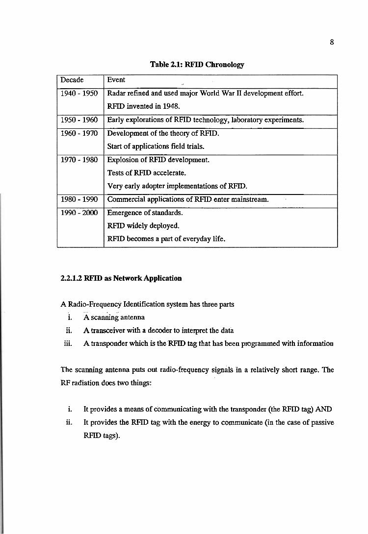
8
Table 2.1: RFID Chronology
2.2.1.2 RFID as Network Application
Decade
1940 - 1950
1950 - 1960
1960 - 1970
1970 - 1980
1980 - 1990
1990 - 2000
A Radio-Frequency Identification system has three parts
i. A scanning antenna
ii. A transceiver with a decoder to interpret the data
iii. A transponder which is the RFID tag that has been programmed with information
Event
Radar refined and used major World War I1 development effort.
RFID invented in 1948.
Early explorations of RFID technology, laboratory experiments.
Development of the theory of RFID.
Start of applications field trials.
Explosion of RFID development.
Tests of RFID accelerate.
Very early adopter implementations of RFID.
Commercial applications of RFID enter mainstream.
Emergence of standards.
RFID widely deployed.
RFID becomes a part of everyday life.
The scanning antenna puts out radio-frequency signals in a relatively short range. The
RF radiation does two things:
i. It provides a means of communicating with the transponder (the RFID tag) AND
ii. It provides the RFID tag with the energy to communicate (in the case of passive
RFID tags).

The main key part of the technology is the RFID tags. The passive RFID tags do not
need to contain batteries, and can therefore remain usable for very long periods of time
or even decades.
The scanning antennas can be permanently affixed to a surface; handheld antennas
are also available. They can take whatever shape you need; for example, you could build
them into a door frame to acoept data from persons or objects passing through.
When an RFID tag passes through the field of the scanning antenna, it detects the
activation signal from the antenna. That "wakes up" the RFID microchip, and it
transmits the information on its microchip to be picked up by the scanning antenna.
In addition, the RFID tag may be of one of two types. Active RFID tags have their
own power source; the advantage of these tags is that the reader can be much farther
away and still get the signal. Even though some of these devices are built to have up to a
10 year life span, they have limited life spans. Passive RFID tags, however, do not
require batteries, and can be much smaller and have a virtually unlimited life span.
RFID tags can be read in a wide variety of circumstances, where barcodes or other
optically read technologies are useless.
i. The tag need not be on the surface of the object (and is therefore not subject to
wear)
ii. The read time is typically less than 100 milliseconds
iii. Large numbers of tags can be read at once rather than item by item.
According to Turner F. (2005), "InCom is the developer of the first contactless
attendance taking system (patent pending), which also compiles the average daily
attendance requirements for public schools. The RFID system requires only a 16 - 24
digit number, assigned during tag production, to identify a student, thus enhancing speed
and accuracy, without sacrificing privacy."
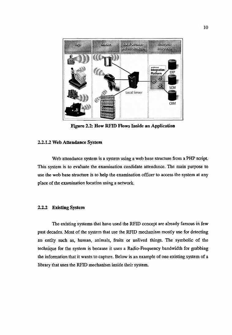
Figure 2.2: How RFID Flows Inside an Application
2.2.1.2 Web Attendance System
Web attendance system is a system using a web base structure from a PHP script..
This system is to evaluate the examination candidate attendance. The main purpose to
use the web base structure is to help the examination officer to access the system at any
place of the examination location using a network.
2.2.2 Existing System
The existing systems that have used the RFID concept are already famous in few
past decades. Most of the system that use the RFID mechanism mostly use for detecting
an entity such as, human, animals, fruits or unlived things. The symbolic of the
technique for the system is because it uses a Radio-Frequency bandwidth for grabbing
the information that it wants to capture. Below is an example of one existing system of a
library that uses the RFID mechanism inside their system.
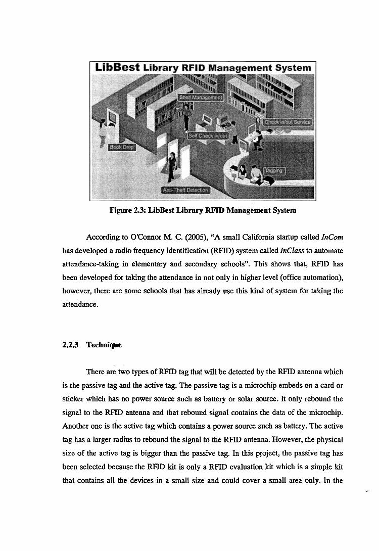
Figure 23: LibBest Library RFID ~ a n a ~ e m e n t System
According to Ot&nnor M. C. (2005), "A small California startup called InCom
has developed a radio frequency identification (RFID) system called Inclass to automate
attendance-taking in elementary and secondary schools". This shows that, RFID has
been developed for taking the attendance in not only in higher level (office automation),
however, there are some schools that has already use this kind of system for taking the
attendance.
2.23 Technique
. .
There are two types of ' W I D tag that will be detected by the RFID antenna which
is the passive tag and the active tag. The passive tag is a microchip embeds on a card or
sticker which has no power source such as battery or solar source. It only rebound the
signal to the RFID antenna and that rebound signal contains the data of the microchip.
Another one is the active tag which contains a power source such as battery. The active
tag has a larger radius to rebound the signal to the RFID antenna. However, the physical
size of the active tag is bigger than the passive tag. In this project, the passive tag has
been selected because the RFID kit is only a RFID evaluation kit which is a simple kit
that contains all the devices in a small size and could cover a small area only. In the I .
other hand, for taking the examination attendance, it is preferred to use a passive tag
because the antenna could be build in inside the entrance door to the examination hall.
For the system side, the technique for user friendly is highly recommended for
the system because it handles important data. Thus the system must give the 100%
correct data. When the system use the web-base technique for the coding structure, thus
it help the user to access the system without installing any application besides the web
browser. User may use the simple web browser such as Internet Explorer or Firefox
Mozilla to access the system. The system will have a server that contains the full
database of all examination candidates.
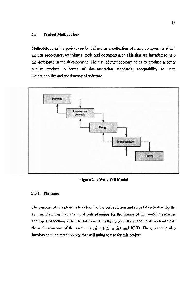
2.3 Project Methodology
Methodology in the project can be defined as a collection of many components which
include procedures, techniques, tools and documentation aids that are intended to help
the developer in the development. The use of methodology helps to produce a better
quality product in terms of documentation standards, acceptability to user,
maintainability and consistency of software.
Figure 2.4: Waterfall Model
23.1 Planning
The purpose of this phase is to determine the best solution and steps taken to develop the
system. Planning involves the details planning for the timing of the working progress
and types of technique will be taken next. In this project the planning is to choose that
the main structure of the system is using PHP script and RFID. Then, planning also
involves that the methodology that will going to use for this project.
2.3.2 Requirement Analysis
The purpose of this phase is to build logical model of this application. In addition, this
phase also needed to understand the applications, fact finding technique like document
reviews, surveys, observations, and sampling must be made to identify application
requirement, software requirement and hardware requirement. In this phase, what kind
of data requirement and the functional requirement will been decide. The data
requirement consists of the captured data by the RFID module and the existing data
inside the database.
2 3 3 Design
This phase will produce draft of the system architecture and the prototype of the
application that will satisfy all requirement analysis. At this phase the user interface and
all necessary input and process will be identify. This phase also determine the
application architecture, which is going to shows how to transform the logical design
into basic system coding to generate the first prototype of the system. The result for this
phase application interface and system design specification. For this project, the design
will be create using the Dreamweaver MX 2004.
23.4 Implementation
During this implementation phase, the system will be constructed. All codes are
generated inside this, phase. At the end of this phase, system should running and most of
the function for the system should be able to use. Based from the previous phase, from
the prototype, the system will become the first version inside this phase. In this phase, it
will also including the installation of the Apache Web Server, MySQL database, RFID
Evaluation kit, and generating the server side web script (PHP):

2.3.5 Testing
This phase will evaluate or verify that application that was developed. This phase will
have a simulation data which will simulate the true database for the system. This is to
test the functionality of the system in comparing a capture data with a database. Beside,
all the functionality that may cause errors or problems to the system must be specified
inside this phase because, the final result of the system is a very high priority and
important. However, the testing phase will only cover to overcome the problem
statement and the system objectives.
2.4 Project Requirement
2.4.1 Software Requirement
Table 2.5: Sohare Requirement
Quantity 1 Unit
1 Unit
Undefined
Equipment / Tools Macromedia Dreamweaver MX
Adobe Photoshop CS 2
Mozilla Firefox v2.0.3 (Recommended)
Description Application that generate the codes of the PHP scripting.
Professional application that helps to image editing.
Web browser to browse the system for server and each client computers.

2.4.2 Hardware Requirement
Table 2.6: Hardware Requirement
2.43 Operating System and Application Server Requirement
Table 2.7: Operating System and Application Server Requirement
Equipment Web Server and Database Server
Description Server that will become the web server and the database server.
Basic Requirement: Intel Pentium 4 2.4 GHz Ram 256 Mb Hardisk 20 Gb 101100 Mbps Ethernet LAN NIC
Quantity 1 Unit
Quantity 1 Unit
1 Unit.
OSIServers Windows XP Service Pack 2
AppServ version 2.5.8
Description The operating system that install into the server.
An open application contains Apache web server, MySQL database and PHP. This program will install into the server.
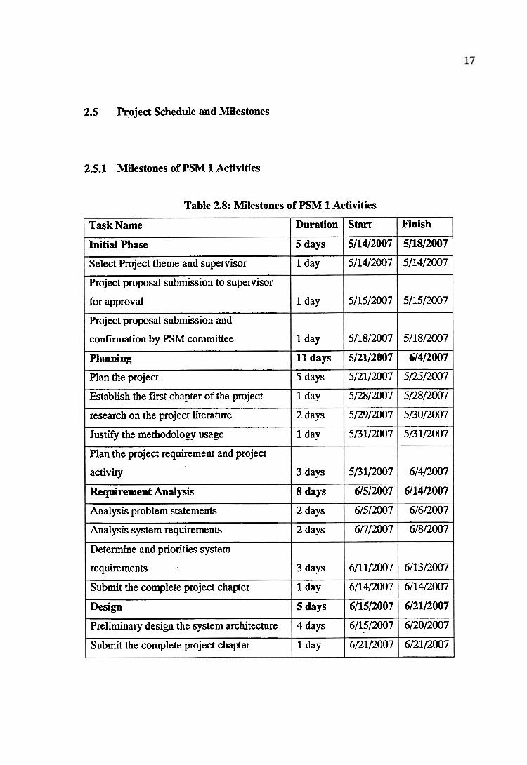
2.5 Project Schedule and Milestones
2.5.1 Milestones of PSM 1 Activities
Table 2.8: Milestones of PSM 1 Activities
Finish
5/18/2007
5/14/2007
5/15/2007
5/18/2007
6/4/2007
5/25/2007
5/28/2007
513012007
513 112007
6/4/2007
6/14/2007
6/6/2007
6/8/2007
6/13/2007
6/14/2007
6/21/2007
612012007
6/21/2007
Task Name
Initial Phase
Select Project theme and supervisor
Project proposal submission to supervisor
for approval
Project proposal submission and
confirmation by PSM committee
Planning
Plan the project
Establish the first chapter of the project
research on the project literature
Justify the methodology usage
Plan the project requirement and project
activity
Requirement Analysis
Analysis problem statements
Analysis system requirements
Determine and priorities system
requirements
Submit the complete project chapter
Design
Preliminary design the system architecture
Submit the complete project chapter
Duration
5 days
1 day
1 day
1 day
11 days
5 days
1 day
2 days
1 day
3 days
8 days
2 days
2 days
3 days
1 day
5 days
4 days
1 day
Start
5/14/2007
5/14/2007
5/15/2007
5/18/2007
5/21/2007
5/21/2007
5/28/2007
5/29/2007
513 112007
5/31/2007
6/5/2007
6/5/2007
6/7/2007
6/11/2007
6/14/2007
6/15/2007
6/15/2007
6/21/2007
2.5.2 Gantt Chart
* Please Refer to Appendices Section
2.6 Conclusion
In the chapter of literature review and project methodology, it is about on how to
gather lots of benefit information in order to find the right approach to manage
problems, requirements and preferences. The related information is important to
understand how RFID works and why a web-based system is choose to communicate
with the RFID modules. Therefore, research, references and case study are the best
resources to develop the project. From this research and case study it will help to
identify all existing system and technique that are used to develop systems and choose
the most suitable technique to develop this system.
The waterfall design is choosen as the project methodology. The project
methodology will help in designing the system by following each phase to develop this
application and the Gantt chart will be useful in application development. Next chapter,
chapter three; analysis will discuss more detail about project analysis and project
methodology.
...
CHAPTER 111
ANALYSIS
3.1 Introduction
This chapter will discuss the project RAFIDASOl which will be divided in two
main sections. These sections are the problem analysis and the requirement analysis.
The development of the system will be fiom the beginning of the project which
is planning until testing. The requirement analysis for this chapter will helps to
understand the needs of the system either the user side or the system side. This will
include the functional requirements, use case diagrams, actors, and use case description.
3.2 Problem Analysis
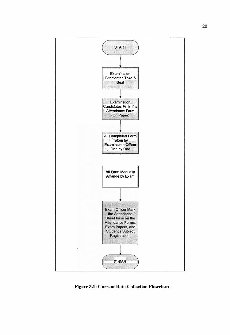
The current situation of collecting the examination candidate attendance is
basically using a manual process. The technical process means that the examination
candidates are using paper to fill in the attendance form and that form will be collected
manually by the examination officer during the examination. Below is the current
flowchart of the examination candidate attendance data collection process.
I
Examination Candidates Take A
Candidates Fill In the AttendanceForm
I
All Completed Form' Taken tw
Examination One by C
All Form Manually Arrange by Exam
FINISH
Figure 3.1: Current Data Collection Flowchart
Based on above chart, it is clearly shown all the technique for gathering the
attendance data is using a manual process.
The details processes are examination officer will place the attendance form for
the examination candidate on the candidate's table. Then, examination candidates will
enter the examination hall and take their own seat. After that, most of officer will ask the
candidates to fill in the attendance form with the correct data before the exam start. After
the attendance form has been filled, the form will be placed at the top right of the exam
candidate tables so that it is easy for exam officers to collect the form.
Most of the time, the exam officers will collect the form after the examination
started. After that, the form will be arranged based on the exam's subject. Then the exam
officer will mark the attendance sheet based on the examination's forms, total of
collected answer sheet and the student's registration sheets. Thus, the RAmDASOl will
try to overcome the manual process for gathering and finalize the result of the
examination attendance efficiently.
Now a day, most of systems are developed for minimized the human technical
errors. It is same like RAFIDASO1. It is develop to reduce the technical error during data
collection process. Besides, using a digital and centralized system, RAFIDASOl could
give best accuracy using the RFID technology because the data are stored inside a
microchip and a database.
For example like one examination candidates might misspell their name or
metric number. If there are two same metric numbers are written inside one examination
subject by two different students, it is clearly hard to define the solution to retrieve the
correct data again. Thus, with the RAFIDASOl, this problem will not occur anymore
because the RFID tag will contain the unique data about each examination candidates
(student).
3.3 Requirement Analysis
.*
In this section, the data and function of the system will be briefly discussed. All
the requirements will be documented and it wills going to use as the reference in the
next phase which is system design phase.
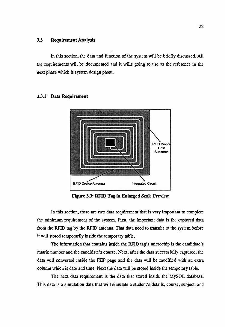
33.1 Data Requirement
\ RFID Device
Host Substrate
/ I RRDDeYice Antema \
Integrated Circuit I Figure 33. RFID Tag in Enlarged Scale Preview
In this section, there are two data requirement that is very important to complete
the minimum requirement of the system. First, the important data is the captured data
from the RFID tag by the RFID antenna. That data need to transfer to the system before
it will stored temporarily inside the temporary table.
The information that contains inside the RFID tag's microchip is the candidate's
matric number and the candidate's course. Next, after the data successfully captured, the
data will converted inside the PHP page and the data will be modified with an extra
column which is date and time. Next the data will be stored inside the temporary table.
The next data requirement is the data that stored inside the MySQL database.
This data is a simulation data that will simulate a student's details, course, subject, and

examination details. This data will be compared with the data inside the temporary table
to gain the final result of the examination attendance.
3.3.2 Functional Requirement
The functional requirements that need to be embraced in the system in order to
fulfill the requirement and satisfy the user needs and the most important thing is the
system able to deliver the service to the user efficiently base on the project objective and
overcome the problem statement.
As the analysis has been carried out on the business and problem studies during
the analysis phase, the business requirements have been identified. The requirements
will be used as a blueprint to design the system modules or functions.
The system is divided into six major functions which user login, student database
manager, manage student's RFID tag information, capture data from the RFID tags,
compare the captured data with the current database and display the attendance result.
Below is the details explanation about each function for the functional requirements.
33.2.1 System User's Login and Authorization
This function is the main function to authenticate the user for the system. It is the
main gate for the user to use all the function of the system. It also becomes one of the
security measurements to ensure that only authorized users that have a valid password
and username can access the system.

3.3.2.2 View Attendance
The view attendance function is to help user to view or print the attendance result
for the previous examination.
33.23 Student's RFID Tag Manager
RFID tags that is embedded on the student's metric card is contains the details of
the students. Thus, the tags must have a channel so that it could manipulate the data that
will store inside the RFID tag. This function allows user or administrator to write, erase
data inside the RFID tag.
33.2.4 Capture Data from the RFID Tag
This function is to enable the system to know which candidates are present for
the examination. All data that is captured will be assigned as the present candidates.
33.2.5 Compare the Captured Data with the Current Database
This function will allow the system to determine that if the candidates are
registered for that examination, however if they fail to attend the exam or fail to bring
the metric card, the system will considered that the candidates is absent. This means that
if the database server founds that there are no equal data that has captured, the data will
be considered as an absent student.