stuart jack & hamish cameron fusion erp - caribbean tan volume calculation presentation... ·...
TRANSCRIPT

2006 - SEP
Stockpile Volume Calculation
In conjunction with
Supplied by Stuart Jack & Hamish Cameron Fusion ERP
“..any sufficiently advanced technology is indistinguishable from magic.” Arthur C. Clark

FRAME WORK OF PRESENTATION
INTRODUCTIONPOWER POINTDEMOS:
Volumetric calculation of a stockpileInputs (rail trucks and trailers)Outputs (conveyors & containers)Other
DISCUSSION / QUESTIONS

Digital System, record
Real time monitoring
Layout of stockpiles
PREDICT AND ALARM
Automatic systems, no human involvement
CCTV / IP
Decreased costs, improved performance

Why do Image Analysis?
! Better Definition of Contrasting Areas! Improved Precision/Accuracy in
Measurements! Reproducibility of Results! Higher Throughput than Manual Methods

A Word About Our Eyes!Eyes are very good contrast adjusters, but
not good for distinguishing subtle variations in color
!Eyes can discern about 30 continuous levels of gray or color in a field of view
!Eyes are not good judges of distance!Eyes cannot accurately reproduce
measurements

Which is BIGGER / LONGER???

IMAGING DEVICE (X NO OF CAMERAS)
Frame Grabber / IP
IASoftware
PC Station
SYSTEM CONFIGURATIONSYSTEM CONFIGURATION

Fusion ERP
Visual / Audio SMS / E-Mail Alarms
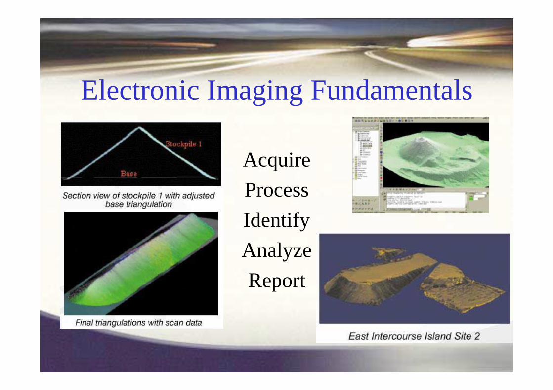
Electronic Imaging Fundamentals
AcquireProcessIdentify AnalyzeReport

Arguably, the most important aspect of all
!Proper setup of imaging apparatus is vital
!Obtain maximum contrast and dynamic range
!Reduce “noise” and other unwanted artifacts
Acquiring the Image

Reporting Data

Export to 3rd PartyExport to 3rd Party
• All data available via Fusion ERP
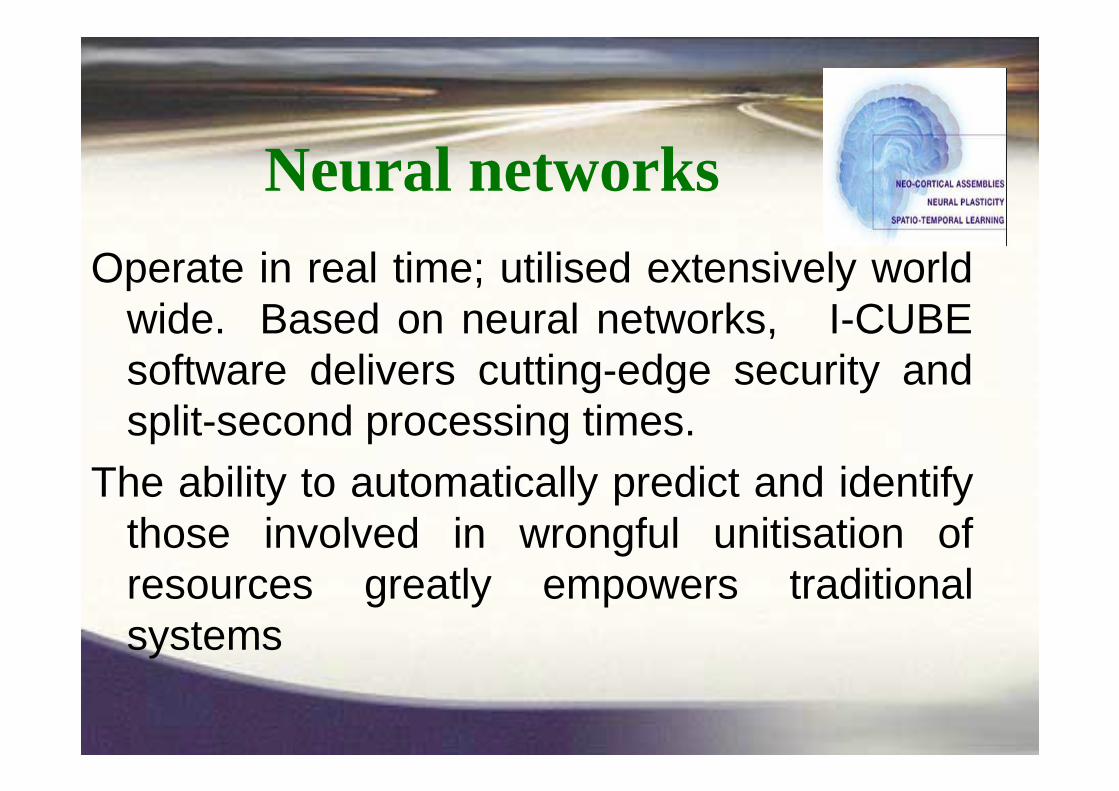
Neural networksOperate in real time; utilised extensively world
wide. Based on neural networks, I-CUBE software delivers cutting-edge security and split-second processing times.
The ability to automatically predict and identify those involved in wrongful unitisation of resources greatly empowers traditional systems

U.S.A.
Mexico
Colombia
Brazil
Spain U.K. Holland Hungary Litha Italy Israel
China
Hong Kong
Korea
Taiwan
Thailand
Singapore
Argentina South Africa Australia
����

Camera OPTIONS

• The traditional means of connecting cameras in machine vision (and other similar applications) is through a dedicated frame grabber/ image acquisition board installed in a PC.
PC

• Several computer industry based interfaces, such as Ethernet, USB and FireWire have been early candidates for serving as a digital serial camera interface.
• Shortcomings in transmission speed, transmission efficiency and standardization ruled these candidates out for many years, and the industry has continued to use frame grabber based solutions.
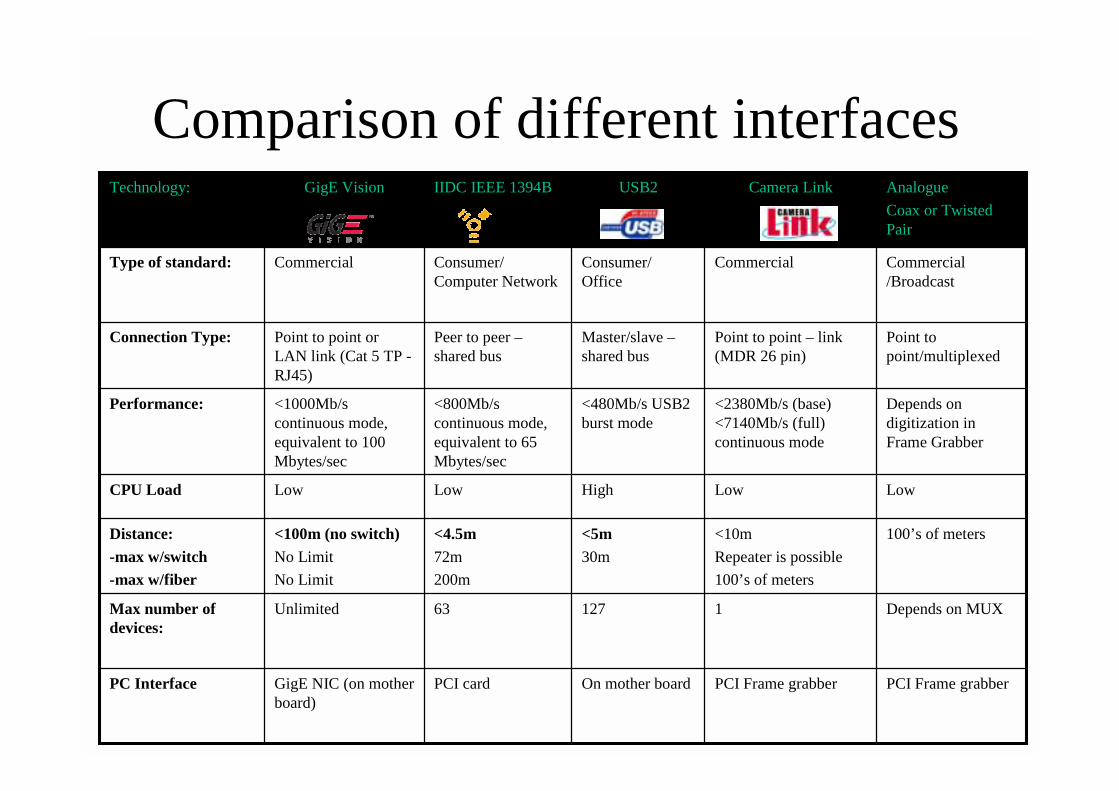
Comparison of different interfaces
LowLowHighLowLowCPU Load
PCI Frame grabber
1
<10mRepeater is possible100’s of meters
<2380Mb/s (base) <7140Mb/s (full) continuous mode
Point to point – link (MDR 26 pin)
Commercial
Camera Link
PCI Frame grabberOn mother boardPCI cardGigE NIC (on mother board)
PC Interface
Depends on MUX12763UnlimitedMax number of devices:
100’s of meters<5m30m
<4.5m72m200m
<100m (no switch)No LimitNo Limit
Distance:-max w/switch-max w/fiber
Depends on digitization in Frame Grabber
<480Mb/s USB2 burst mode
<800Mb/s continuous mode, equivalent to 65 Mbytes/sec
<1000Mb/s continuous mode, equivalent to 100 Mbytes/sec
Performance:
Point to point/multiplexed
Master/slave –shared bus
Peer to peer –shared bus
Point to point or LAN link (Cat 5 TP -RJ45)
Connection Type:
Commercial /Broadcast
Consumer/ Office
Consumer/ Computer Network
CommercialType of standard:
Analogue Coax or Twisted Pair
USB2IIDC IEEE 1394BGigE VisionTechnology:
Adapting Gigabit Ethernet for Vision• Gigabit Ethernet in itself provides 10 times higher bandwidth than
100 BaseT ethernet, • However, the inherent overhead of Ethernet for computer networks
using standard TCP/IP Windows stack makes it less attractive fordemanding applications due to:– Small packets– High CPU usage– By adopting a modified protocol [based on UDP] with “jumbo” packets and
by implementing a high performance driver reducing CPU usage to a few percent, an attractive solution is created.
• This standard is named GigE Vision.
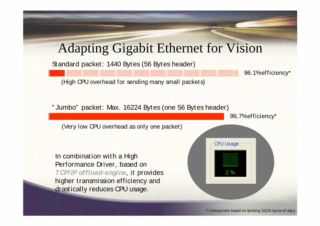
Adapting Gigabit Ethernet for VisionStandard packet: 1440 Bytes (56 Bytes header)
”Jumbo” packet: Max. 16224 Bytes (one 56 Bytes header)
96.1% efficiency*
99,7% efficiency*
In combination with a High Performance Driver, based on TCP/IP offload-engine, it provides higher transmission efficiency and drastically reduces CPU usage.
(High CPU overhead for sending many small packets)
(Very low CPU overhead as only one packet)
*) Comparison based on sending 16224 bytes of data
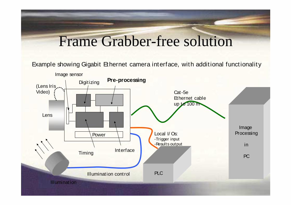
Frame Grabber-free solution
Lens
Image sensor
Digitizing Pre-processing
Timing Interface
PLC
Cat-5eEthernet cableup to 100 m
Local I/Os:-Trigger input-Results output
Illumination control
Image Processing
in
PC
Illumination
(Lens IrisVideo)
Power
Example showing Gigabit Ethernet camera interface, with additional functionality

100110001010001110001010011100100100011101100011001010001000
PC
PC
Possible system configurationsPoint-to-point
(One camera, one PC)
GigESwitch
Many-to-one(Multiple cameras, one PC)
One-to-many (broadcast)
(One or several cameras, with several PCs)
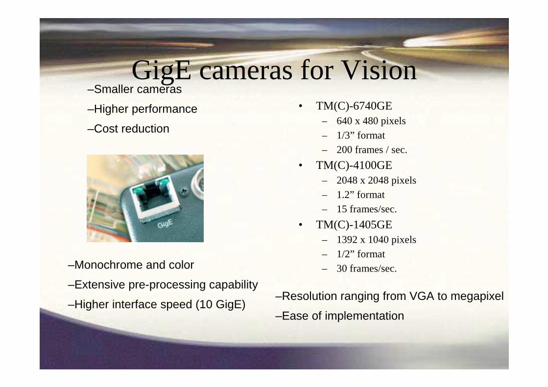
GigE cameras for Vision• TM(C)-6740GE
– 640 x 480 pixels– 1/3” format– 200 frames / sec.
• TM(C)-4100GE – 2048 x 2048 pixels– 1.2” format– 15 frames/sec.
• TM(C)-1405GE – 1392 x 1040 pixels– 1/2” format– 30 frames/sec.
–Smaller cameras
–Higher performance
–Cost reduction
–Monochrome and color
–Extensive pre-processing capability
–Higher interface speed (10 GigE)–Resolution ranging from VGA to megapixel
–Ease of implementation

Requirement: Requirement: To provide OPTICAL To provide OPTICAL technology to calculate stockpile technology to calculate stockpile volume measurements. volume measurements.
MONITORING & REPORTING of all MONITORING & REPORTING of all INPUTS and OUTPUTS, the weight of:INPUTS and OUTPUTS, the weight of:
--Trucks, containersTrucks, containers
-- Trains, Conveyors etc. Trains, Conveyors etc.

Volume CalculationConventional methods of surveying are over-
shadowed when it comes to volume calculations.
These following examples show the speed and accuracy of this method, and highlight how safety is an important issue. Volumes of stockpiles can be accurately and rapidly measured.

Volume Calculation Case StudiesImproving Productivity
As companies employ total quality management methods to increase their competitive advantage, accurate volume measurement is becoming vital. This method delivers reliable results for reconciliation and contractor payments. An
ore stockpile in North America.

Volume Calculation Case StudiesStockpiles for varying resources have been scanned:- Ore stockpiles in the Hamersley Iron port facilities- Mill stockpiles at PT Freeport Grasberg site - Coal stockpiles at the Wesfarmers Coal site - Multiple product stockpiles at the Penrice Soda
Products chemical grade limestone mine
The results far exceed the speed and accuracy of conventional methods
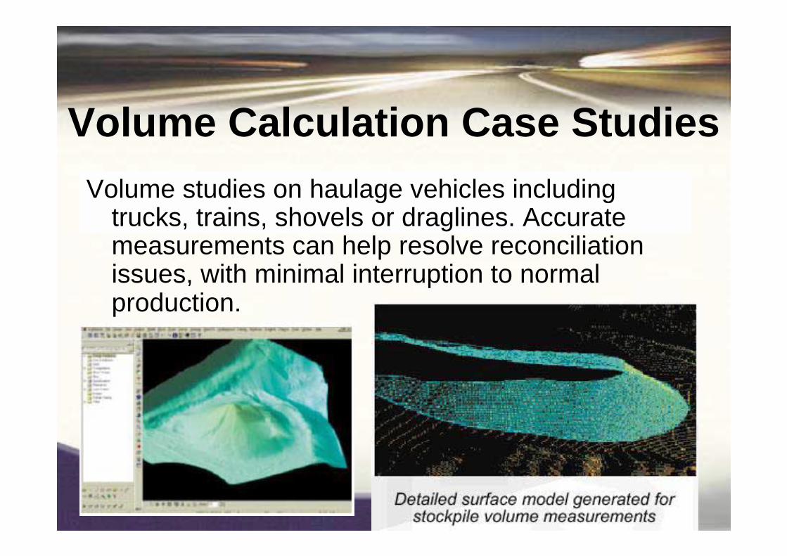
Volume Calculation Case StudiesVolume studies on haulage vehicles including
trucks, trains, shovels or draglines. Accurate measurements can help resolve reconciliation issues, with minimal interruption to normal production.

Volume Calculation Case StudiesCone stockpiles pose a safety risk to surveyors.
Conventional surveying methods are impossible due to the reeling of the stockpile and because the stockpile is often fed from above and extracted from below. Remote access removes the danger, besides providing more accurate volumes., Due to safety reasons Anaconda at Murrin Murrin operations, it has previously proved difficult to obtain good volumes. This approach has saved many hours of work, providing accurate results which are unobtainable by other methods

Volume Calculation Case StudiesBelow is a large 290m long, 15m high coal
stockpile, and a smaller reclaimed stockpile. The 3D models provide a realistic representation of
the surfaces, giving more accurate volumes compared to more commonly used methods.
OOpptical tical CChharacter aracter RRecognitionecognition

Tracking trains / truck / container from origin to destination:Reconciling weight & Contents
Tracking and reporting
countrywide

• Non-intrusive, computerised method of matching a Vehicle Licence Plate to a database of registration numbers.
• System includes camera/illumination units, hardware and software (application + recognition library)
• Automatically reads License Plate number• Displays, records and transmits vehicle
image and recognition results• Can compare plate number to database
and activate alarm (IP/RS232/DEE)

1 - Capture 2 – Find object
3 – OCR
4 – Report
5 easy steps:
5 – Alarm
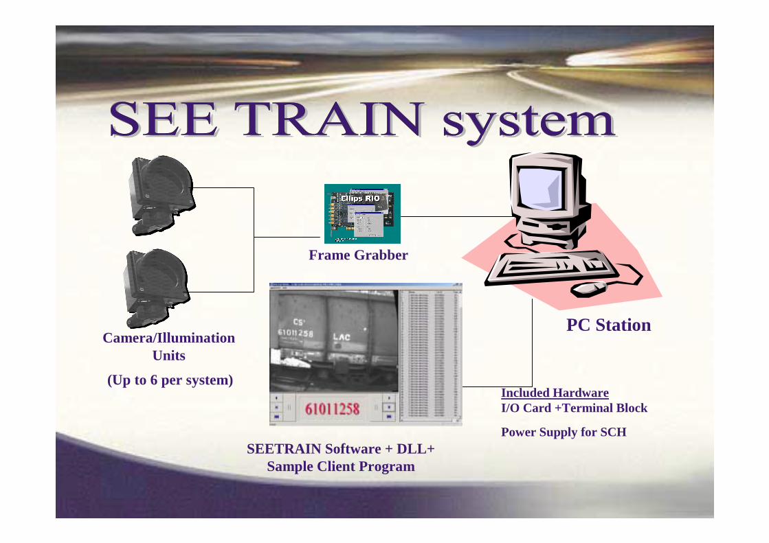
Camera/IlluminationUnits
(Up to 6 per system)
Frame Grabber
SEETRAIN Software + DLL+Sample Client Program
PC Station
Included HardwareI/O Card +Terminal Block
Power Supply for SCH

SEE TRAIN Installation for TWO POINTS
TRAIN approaches trigger zone
Camera /Illumination unit
PC Station
Train Sensor (camera zone or loop on the track)
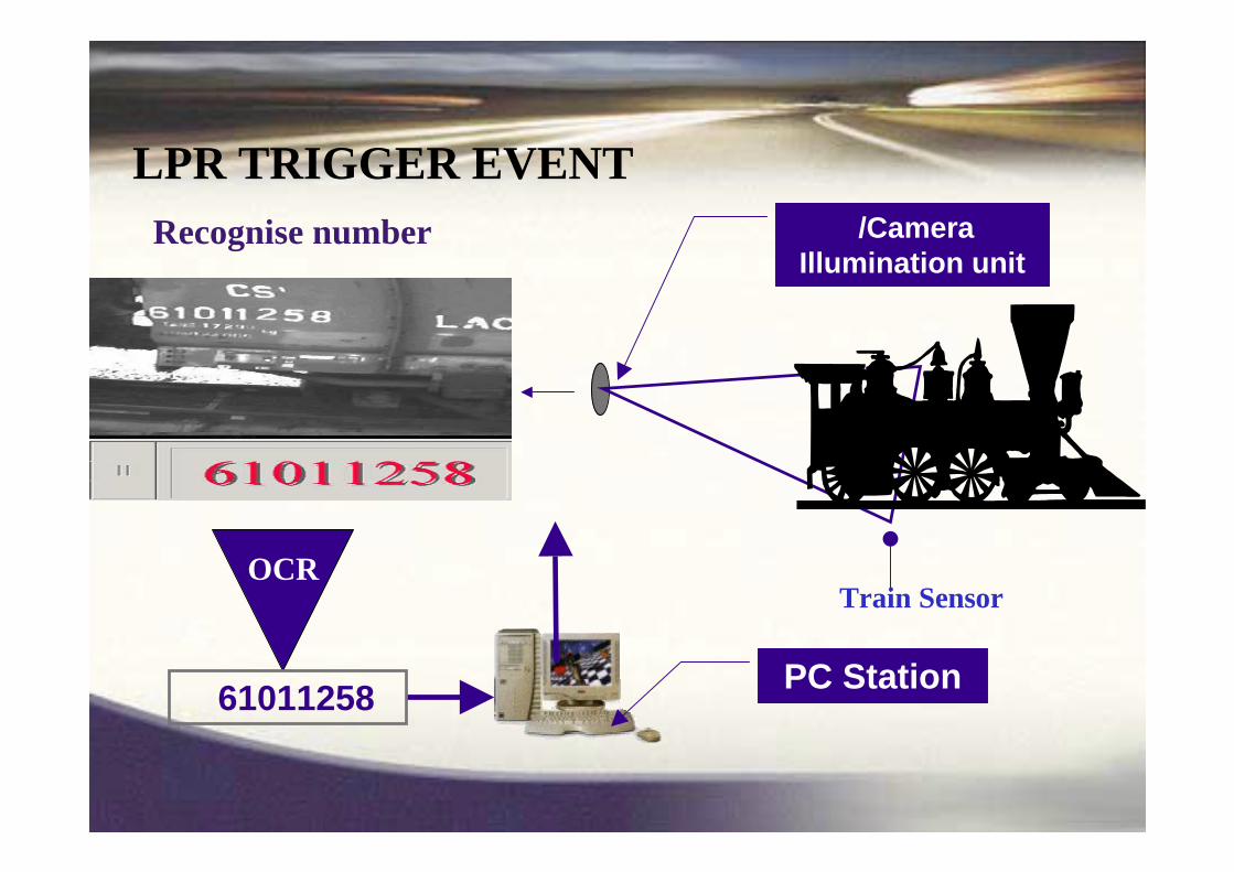
Camera /Illumination unit
OCR
61011258
Train Sensor
Recognise number
PC Station
LPR TRIGGER EVENT

Recognition Rate: 0.1 sec
Options exist to capture LOADinformation and link load to number
Picture of load, possibly compared to load when train
departed
LOAD
captured

Recognition Rate: 0.1-1 sper vehicle (or 1-3 /s)
Vehicle logged at both POINT A & B.If weight differs by more than 1%, alarm generated and variance investigated.

Data Analysis Data Analysis –– OCR success per dayOCR success per day

PC-FREE single-lane logging
Easy 2-Screws Installation
PC-Free stand-alone unit
Low Cost!
Obtain or update list, by: Micro-terminal or GSM or PC
Revolutionary!


CContainerontainer CCode ode RRecognitionecognition

• See/Gate
• See/Crane
• See/Train
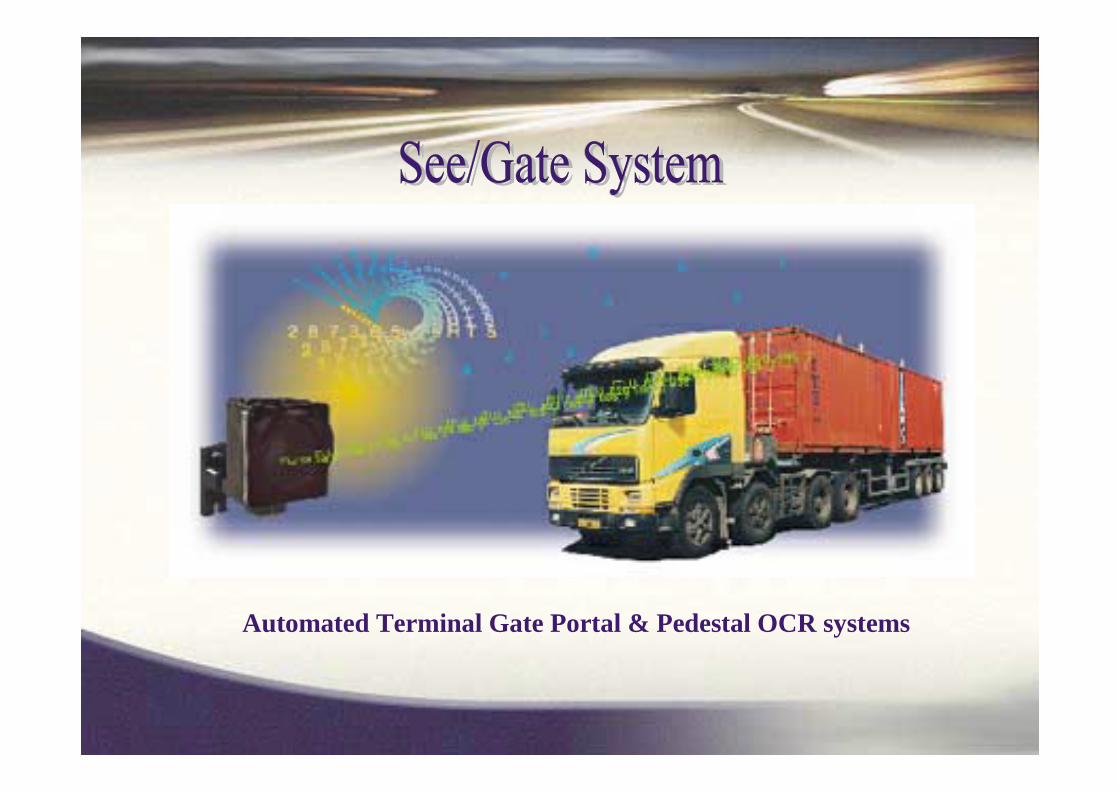
Automated Terminal Gate Portal & Pedestal OCR systems

• Automatically reads Container ID and Truck plate + optional Chassis or
Wagon ID
• Located/Installed At Port gates (each system controls one lane)
• Scans the Containers/Truck in motion
• Displays, records & transmits
images and results
• Turn-Key system (cameras/Illumination,
hardware and software)

• Handles all container types (20, 40, 45, 20-20) ISO 6346 ID formats
• Simple configuration
• Fast response (output in seconds)
• Fully automatic process

• 5 Camera/Illumination units installed at Gate Area (LPR + CCR)
• 2 Additional Camera/Illumination units for Chassis recognition (for USA)
• 3 Container sensors on poles
• 3 Loop Sensors in road
• Solid-state low-energy
illumination


INVESTMENTWe have various financial models which
will enable municipalities to optimiserevenue and budget opportunities.
Most applications of this technology allows for the enhancement of existing and creation of new revenue models.

DEVELOPMENTThe implementation of this technology
will allow for skills transfer to BEE companies and small businesses.
These opportunities will create sustainable revenue models for BEE partners which will result in job creation.

NEXT STEPA meeting with all stake holders to plan an appropriate way forward.Possibly this includes a LIVE DEMO orA visit to an exisiting site orA system design around an exiting port orA price for a typical solution orSome other suitable way to move forward
