sts – 2013/14 exercise n. 3 satellite antenna - construction and setting Ľ. maceková
TRANSCRIPT

STS – 2013/14Exercise
N. 3Satellite antenna
- construction and setting
Ľ. Maceková

Now, we need some knowledge about antenna
3
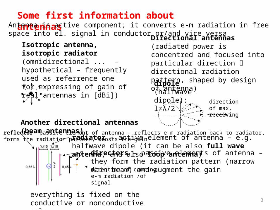
Some first information about antennas
Isotropic antenna, isotropic radiator (omnidirectional ... – hypothetical – frequently used as referrence one for expressing of gain of real antennas in [dBi])
Directional antennas (radiated power is concentred and focused into particular direction directional radiation pattern, shaped by design of antenna)
radiator – active element of antenna – e.g. halfwave dipole (it can be also full wave antenna, and also loop antenna)
directors – passive elements of antenna – they form the radiation pattern (narrow main beam) and augment the gain
reflector– passive element of antenna – reflects e-m radiation back to radiator, forms the radiation pattern, boosts the gain
dipole (halfwave dipole): l=λ/2
direction of max. receiving
everything is fixed on the conductive or nonconductive pole
Another directional antennas (beam antennas)
direction of comming e-m radiation /of signal
Antenna is active component; it converts e-m radiation in free space into el. signal in conductor or/and vice versa

radiator (dipole)
- Then, Yagi antenna and its radiation pattern:
beamwidth of antenna (it is angle – in slovak language šírka zväzku, smerový uhol)
-3dB point (half power)
max. energy (power)

Fig. Illustration of antenna pattern in rectangular coordinates (this is „E“ plane; electrical intensity in dependence on angle) for typical 10-elements Yagi antenna
... and in polar coordinates

Btw., we have also quarter wave pole antenna (Marconi antenna):
coaxial cable
Fig. Relation between both current and voltage waves induced in 1/4-wave antenna.

7
8
- Antenna designers try to enhance the angle effectivity (and gain) of antenna various types and shapes of reflectors and radiators; for satellite receiving, there are parabolic reflectors (“dish”)

9

Obr. : Hitachi
active radiation flats (interconnected)
Flat antenna

11
Reflector antennas – parabolic, dish antennas
Symmetrical, with radiator in the receiving direction
Ofset antenna (upper cut of parabolic surface – advantages: less proportions, doesn’t gather snow, dirt ...)
Ofset – Cassegrain (main reflector and hyperboloidal subreflector...)
Offset-Fed, Gregorian antenna
radiator (convertor)
reflector

12
Fig. footprint – area covered by signal from sat. antenna with several radiators, from 1 GEO-satellite (3 GEO satellites together cover entire Earth –up to 75th parallel)
Fig. sat. antenna with several radiators and one dish

13
Position of satellite and setting of receiving antenna - azimuth a elevation
www.physicalgeography.net/.../angles_azimuth.jpg
www.srrb.noaa.gov/highlights/sunrise/azelzen.gif
AZIMUT – oriented angle in the horizontal plane – between given direction and north direction (from the view of user)
the plane of horizon or the sea level
Elevation (h) – angle in vertical plane measured from horizontal plane to the line of sight
- another view
LNB skew

h sin
1513.0h cosarctanEL
Intermediate parameter h:
coscosarccos BLSh
Value 0.1513:
1513.010.357866378
10.6378
HR
R3
3
where: S...position of satellite (longitude) in degrees; Easter longitude (°E ) must have negative value (minus) L... longitude of receiver antenna posision; Easter longitude (°E ) must have negative value (minus) B – latitude of receiving position R – Earth radius H – altitude of satellite above Earth
sin
tanarctan180
B
LSAZ
sin
tanarctan'
B
LSAZ
360 'AZAZ
easter is MD, ifMDAZAZreal
westernis MD,ifMDAZAZreal
If we are on south hemisphere:
Correction considering magn.declination:
Calculation of LNB Skew (moving round of Low Noise Block):
tan
sinarctan
B
LSskewLNB
Now, we can calculate both EL-elevation, AZ-azimuth - angles of satellite antenna setting:
Homework: Calculate azimuth and elevation of antenna for receiving chosen satellite in chosen place of Earth surface.
[-] 2
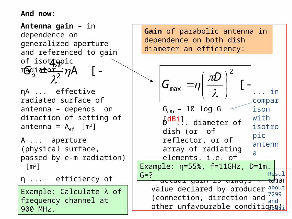
max
D
G
D ... diameter of dish (or of reflector, or of array of radiating elements, i.e. of aperture) [m]
[-]A 4
2
aG
ηA ... effective radiated surface of antenna – depends on diraction of setting of antenna = Aef [m2]
A ... aperture (physical surface, passed by e-m radiation) [m2]
η ... efficiency of aperture (0,35-0,75) [-]
λ ... wavelength [m]- actual gain is always < than value declared by producer (connection, direction and other unfavourable conditions)
GdBi = 10 log G [dBi]
Example: η=55%, f=11GHz, D=1m. G=?
Gain of parabolic antenna in dependence on both dish diameter an efficiency:
And now:
Antenna gain – in dependence on generalized aperture and referenced to gain of isotropic radiator :
Example: Calculate λ of frequency channel at 900 MHz.
Results: about 7299 and 38dBi
... in comparison with isotropic antenna

References:
[1] J. Montana: Introduction to Satellite Communications, George Mason Univ. 2003 (presentation)
[2] Mobilné satelitné komunikácie (Preklad [4])
[3] M.O.Kolawole: Sat. Comm. Engineering.,Marcel Dekker, 2002, USA
[4] S.Omori, H. Wakana, S. Kawase: Mobile satellite Communications, 1998, Artech House, USA.