struts and columns - deukisi.deu.edu.tr/emine.cinar/asm16-struts and columns i… · ·...
TRANSCRIPT

STRUTS AND COLUMNS
Introduction
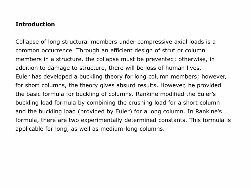
Collapse of long structural members under compressive axial loads is a
common occurrence. Through an efficient design of strut or column
members in a structure, the collapse must be prevented; otherwise, in
addition to damage to structure, there will be loss of human lives.
Euler has developed a buckling theory for long column members; however,
for short columns, the theory gives absurd results. However, he provided
the basic formula for buckling of columns. Rankine modified the Euler’s
buckling load formula by combining the crushing load for a short column
and the buckling load (provided by Euler) for a long column. In Rankine’s
formula, there are two experimentally determined constants. This formula is
applicable for long, as well as medium-long columns.

Many a times, load is eccentrically applied on a column and buckling takes
place at a smaller load than the load given by Euler or Rankine. For
eccentrically loaded columns, expressions for maximum stress have been
derived in the form of a secant formula. Many researchers have modified the
secant formula for eccentrically loaded columns.
Higher-order differential equations have been used for determining the
buckling loads of columns with different end conditions. Moreover, energy
approach is briefly discussed to determine the buckling loads of columns,
taking various shape functions for the deflection curve.

Euler’s Theory of Buckling
Euler has developed a theory of buckling for columns or struts, but
considered the column/strut already buckled under a particular load while
developing the theory of buckling. He has made the following assumptions:
1.material of the column is homogeneous and isotropic,
2.compressive load acting on the column is fully axial,
3.column has failed only due to buckling,
4.weight of the column is negligible,
5.column is initially straight and buckles suddenly at a particular load,
6.fixed ends are rigid and
7.hinged ends are frictionless.

Example 9.1
Consider a column AB with one end fixed and the other
end free, buckled under the load P as shown in the figure.
Length of the column is L. Deflection at free end B is a as
shown, and the buckling load is P. Consider a section of
the column at a distance x from end A.
Column fixed at one end and free at the other end
Bending moment at section XX = P(a − y), or
Solution of this differential equation is y = A sin mx + B cos mx + a where and A and B are constants.
y
x
EIPa
EI
Py
dx
yd
yaPdx
ydEI
2
2
2
2
EIP
m
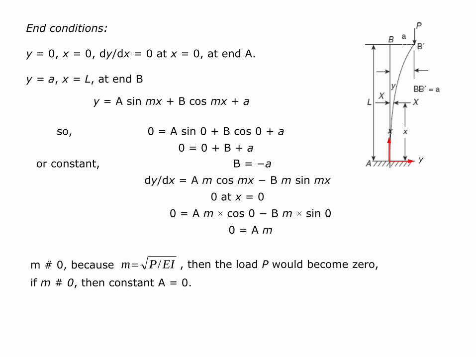
End conditions:
y = 0, x = 0, dy/dx = 0 at x = 0, at end A.
y = a, x = L, at end B
so, 0 = A sin 0 + B cos 0 + a
0 = 0 + B + a
or constant, B = −a
dy/dx = A m cos mx − B m sin mx
0 at x = 0
0 = A m × cos 0 − B m × sin 0
0 = A m
m # 0, because , then the load P would become zero,
if m # 0, then constant A = 0.
y
x
y = A sin mx + B cos mx + a
EIPm /

Finally, y = −a cos mx + a
At end B, x = L, y = a
a = −a cos mL + a or,
a cos mL = 0
a # 0, because if a = 0, then no buckling takes place.
so,
mL=p/2 (minimum significant value)
Euler’s buckling load, Pe = p2EI/4L2.
y
x
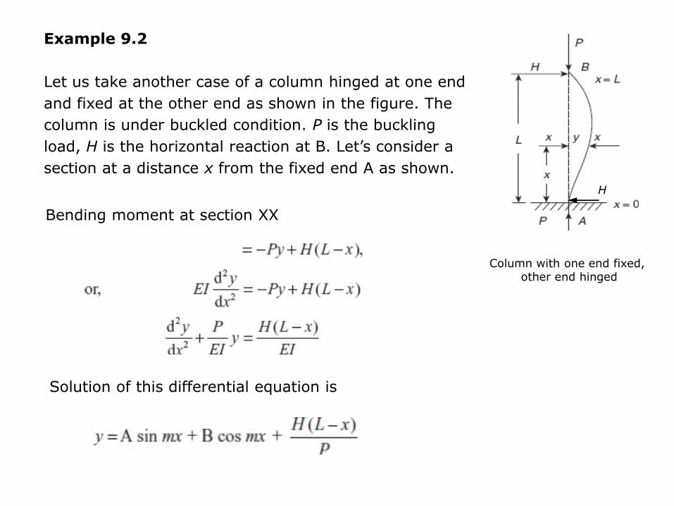
Example 9.2
Let us take another case of a column hinged at one end
and fixed at the other end as shown in the figure. The
column is under buckled condition. P is the buckling
load, H is the horizontal reaction at B. Let’s consider a
section at a distance x from the fixed end A as shown.
Column with one end fixed, other end hinged
Bending moment at section XX
Solution of this differential equation is
H

End conditions x = 0, y = 0
Constant, B = −HL/P Then,
So, Am = H/P
Constant, A = H/mP
Putting the values of A and B in the equation
H

At the end B, x = L, y = 0,
so
or tan mL = mL
H

Exercise 9.1
A column of length L and flexural rigidity EI is hinged at both
the ends. Derive the expression of Euler’s buckling load.
[Hint: M = −Py, y = A sin mx + B cos mx,
End conditions x = 0, y = 0, x = L, y = 0]

Exercise 9.2
Derive the expressions for Euler’s buckling load of a column fixed at both the
ends. Length of column L, buckling load P . Fixing moments at fixed ends are
MA and MB, respectively.
M at section shown = –Py + MA
y = A sin mx+ B cos mx + MA/ P
End conditions x = 0, y = 0, dy/dx = 0
x = L, y = 0, dy/dx = 0

and (d) a column with one end fixed and
Equivalent Length
Buckling load of a column is given by Euler’s formula and it depends on the end conditions of a column. However, to express the buckling load formula in a simplified manner, equivalent length of column is determined that is equivalent to the length of column with both ends hinged. This length can be obtained by completing the bending curve of the column with different end conditions similar to the bending curve of a column with both the ends hinged as shown in Figure 1.
Pe = Euler’s buckling load = p2EImin/Le2
Figure 1 (a) A column with both ends hinged, Le = L; (b) a column with both ends fixed, Le = L/2; (c) a
column with one end fixed and the other end hinged,
the other end free, Le = 2L.
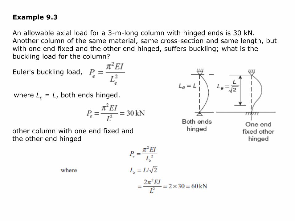
Example 9.3 An allowable axial load for a 3-m-long column with hinged ends is 30 kN. Another column of the same material, same cross-section and same length, but with one end fixed and the other end hinged, suffers buckling; what is the buckling load for the column?
Euler’s buckling load,
where Le = L, both ends hinged.
other column with one end fixed and the other end hinged

Limitations of Euler’s Theory of Buckling
Euler’s theory of buckling is applicable for long columns. If there is a limit on the
slenderness ratio of the column and it is less than this limiting value, then Euler’s
formula gives the value of buckling load that is greater than the crushing load,
which is not possible.
Euler’s buckling load,
where,
E = Young’s modulus
Imin = Ak2min, where A is the area of cross-section
Le = equivalent length, kmin = the minimum radius of gyration
so

Pe /A < σc (the crushing stress of a short column)
Le/Kmin = the slenderness ratio of a column
For mild steel
E = 208 GPa = 208,000 N/mm2
σc = crushing strength
= 320 N/mm2
For mild steel column, the slenderness ratio should be greater than 80, so
that Euler’s formula can be used to predict the buckling load of a column.
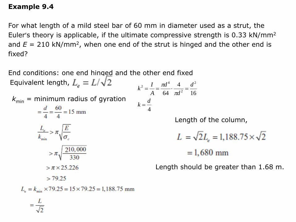
Example 9.4
For what length of a mild steel bar of 60 mm in diameter used as a strut, the
Euler’s theory is applicable, if the ultimate compressive strength is 0.33 kN/mm2
and E = 210 kN/mm2, when one end of the strut is hinged and the other end is
fixed?
End conditions: one end hinged and the other end fixed
Equivalent length,
kmin = minimum radius of gyration
Length of the column,
Length should be greater than 1.68 m.
4
16
4
64
2
2
42
dk
d
d
d
A
Ik
p
p
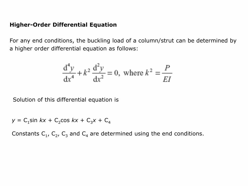
Higher-Order Differential Equation
For any end conditions, the buckling load of a column/strut can be determined by
a higher order differential equation as follows:
Solution of this differential equation is
y = C1sin kx + C2cos kx + C3x + C4 Constants C1, C2, C3 and C4 are determined using the end conditions.

Example 9.5 Let us consider a column with both the ends fixed as shown in the figure.
Column AB of length L is fixed at ends A and B. At the
ends, both the slope and deflection are zero, that is,
the boundary conditions of the column are:
At end A, x = 0, y = 0, dy/dx = 0
At end B, x = L, y = 0, dy/dx = 0
Differentiating y = C1sin kx + C2cos kx + C3x + C4
with respect to x, we get
dy/dx = C1k cos kx − C2k sin kx + C3
Taking x = 0, y = 0, x = L, y = 0, we get,
0 = C1 sin 0 + C2cos 0 + C3 × 0 + C4
0 = 0 + C2 + 0 + C4
0 = C1sin kL + C2cos kL + C2L + C4
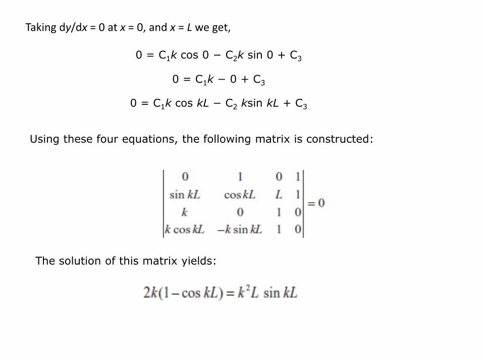
Taking dy/dx = 0 at x = 0, and x = L we get,
0 = C1k cos 0 − C2k sin 0 + C3
0 = C1k − 0 + C3
0 = C1k cos kL − C2 ksin kL + C3
Using these four equations, the following matrix is constructed:
The solution of this matrix yields:

Let us take 1 − cos kL = 0,
cos kL = 0
kL = 0, 2p, 4p - - -
So, kL = 2p (minimum significant value)
or,
Squaring both sides,
Buckling load,
Moreover, sin kL = sin 2p = 0 (also), which will also give P = 4p2EI/L2.
p2LEI
P
22 4pLEI
P
2
24
L
EIP
p
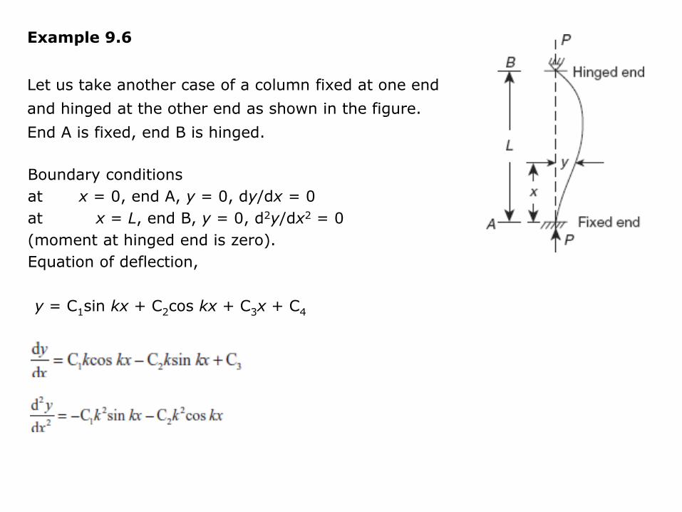
Example 9.6
Let us take another case of a column fixed at one end
and hinged at the other end as shown in the figure.
End A is fixed, end B is hinged.
Boundary conditions
at x = 0, end A, y = 0, dy/dx = 0
at x = L, end B, y = 0, d2y/dx2 = 0
(moment at hinged end is zero).
Equation of deflection,
y = C1sin kx + C2cos kx + C3x + C4
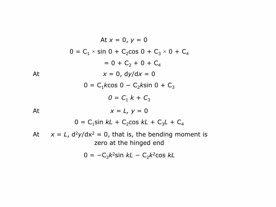
At x = 0, y = 0
0 = C1 × sin 0 + C2cos 0 + C3 × 0 + C4
= 0 + C2 + 0 + C4
At x = 0, dy/dx = 0
0 = C1kcos 0 − C2ksin 0 + C3
0 = C1 k + C3
At x = L, y = 0
0 = C1sin kL + C2cos kL + C3L + C4
At x = L, d2y/dx2 = 0, that is, the bending moment is
zero at the hinged end
0 = −C2k2sin kL − C2k
2cos kL

Using these set of equations, the following matrix is constructed:
or 0 = kL coskL − sin kL
tan kL = kL
tan 0 = θ
Buckling load,
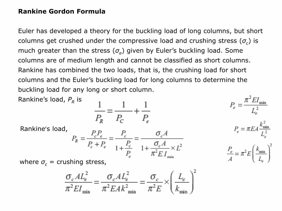
Rankine Gordon Formula
Euler has developed a theory for the buckling load of long columns, but short
columns get crushed under the compressive load and crushing stress (σc) is
much greater than the stress (σe) given by Euler’s buckling load. Some
columns are of medium length and cannot be classified as short columns.
Rankine has combined the two loads, that is, the crushing load for short
columns and the Euler’s buckling load for long columns to determine the
buckling load for any long or short column.
Rankine’s load, PR is
Rankine’s load,
where σc = crushing stress,
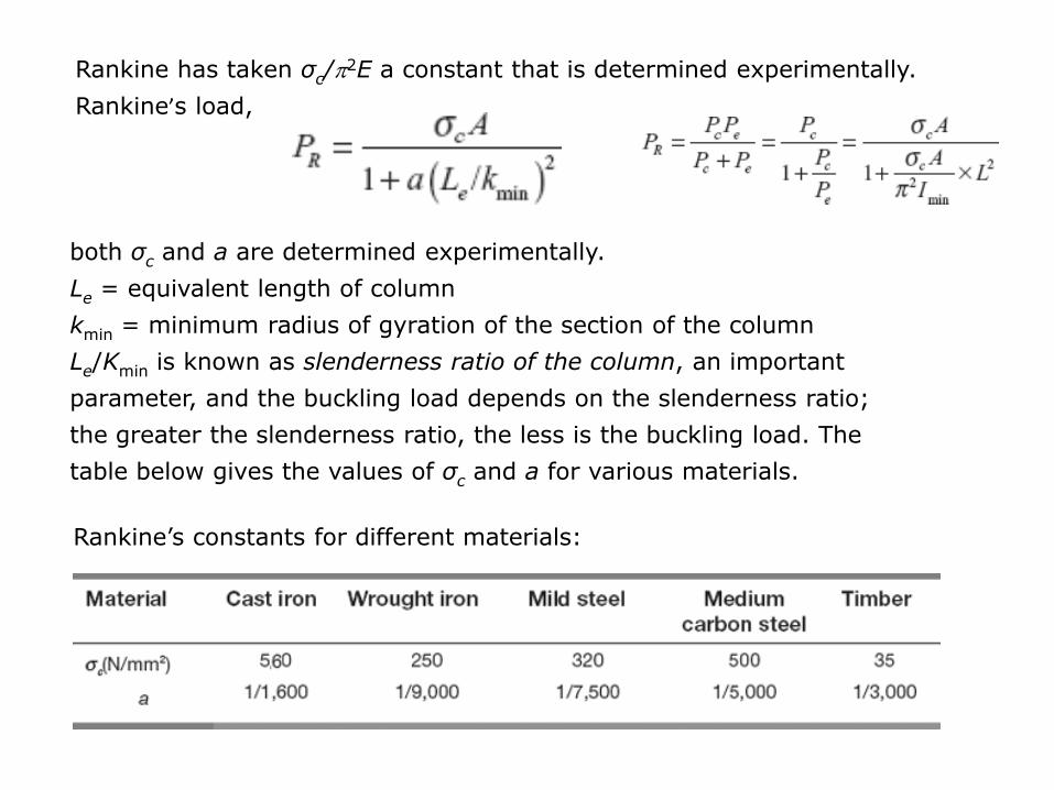
Rankine has taken σc/p2E a constant that is determined experimentally.
Rankine’s load,
both σc and a are determined experimentally.
Le = equivalent length of column
kmin = minimum radius of gyration of the section of the column
Le/Kmin is known as slenderness ratio of the column, an important
parameter, and the buckling load depends on the slenderness ratio;
the greater the slenderness ratio, the less is the buckling load. The
table below gives the values of σc and a for various materials.
Rankine’s constants for different materials:

Example 9.7
A cast iron column of a hollow circular section with an external diameter of
250 mm and a wall thickness of 45 mm is subjected to an axial compressive
load. The column is 7 m long with both ends hinged. Taking factor of safety
(FOS) as 8, determine safe value of P.
Rankine’s constants are, σc = 560 N/mm2, a = 1/1,600
External diameter, D = 250mm
Wall thickness, t = 45mm
Internal diameter, d = 250 − 2 × 45 = 160 mm
Area of cross-section,
Length, L = 7 m = 7,000 mm

End condition: both the ends are hinged
Rankine’s load,
Safe load, P′R = 286.6/8 = 35.83 kN
A
Ik 2

Johnson’s Parabolic Formula
We have learnt so far that buckling loads depend upon the slenderness ratio
(Le /kmin) of the column. As the slenderness ratio increases, the buckling
required for the column decreases. Based on this principle, Johnson has
suggested a formula:
Working stress, σw = σc′[1 − φ(Le/k)] as function of Le/k, slenderness ratio
Taking φ(Le/k) = b(Le2/k2), where b is a constant
σw = σc′[1 − b(L2e/k
2)], an equation of a parabola.
σ’c = allowable stress in compression taking into account the FOS (factor of
safety)
= 110 N/mm2 for mild steel.
Constant, b = 0.00003 for hinged ends
= 0.00002 for fixed ends.
Straight line formula
σw′ = σc′[1 − C(Le/k)], applicable for columns for which the slenderness
ratio is greater than 90.
For structural steel,
σc′ = 140 N/mm2 in compression
C = 0.0054 for hinged ends
= 0.0038 for riveted ends.
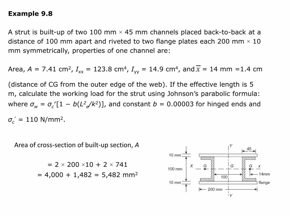
Example 9.8
A strut is built-up of two 100 mm × 45 mm channels placed back-to-back at a
distance of 100 mm apart and riveted to two flange plates each 200 mm × 10
mm symmetrically, properties of one channel are:
Area, A = 7.41 cm2, Ixx = 123.8 cm4, Iyy = 14.9 cm4, and = 14 mm =1.4 cm
(distance of CG from the outer edge of the web). If the effective length is 5
m, calculate the working load for the strut using Johnson’s parabolic formula:
where σw = σc′[1 − b(L2e/k
2)], and constant b = 0.00003 for hinged ends and
σc
′ = 110 N/mm2.
Area of cross-section of built-up section, A
= 2 × 200 ×10 + 2 × 741
= 4,000 + 1,482 = 5,482 mm2

Ixx of built-up section = 2 ×123.8 ×104 + 2 × 200 ×10 × (55)2
= 247.6 ×10⁴ +1210 ×104
= 1457.6 ×104 mm4
Iyy of built-up section (figure) Iyy = 2 ×14.9 ×104 + 2 × 741× (50 +14)2 + 2 ×10 ×
(2002/12)
= 29.6 ×10⁴ + 607 ×104 +1,333.33×104
= 1,970 ×104 mm4 Now,
Imin = Ak2min

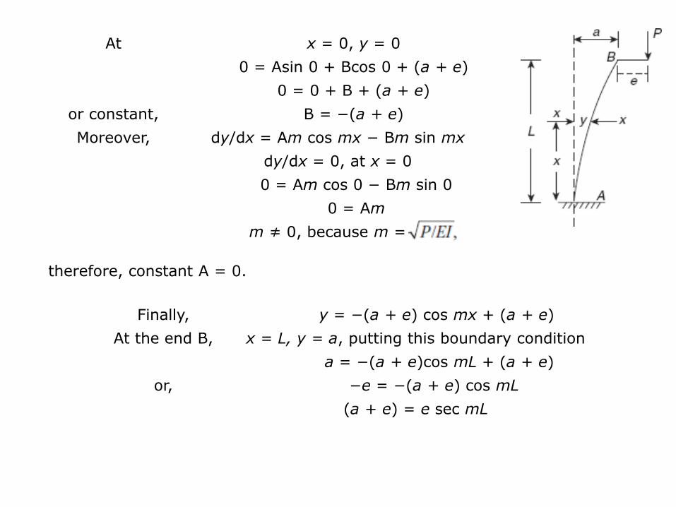
Eccentric Loading of Columns
A column AB of length L loaded eccentrically e (eccentricity
with respect to axis of column) has buckled under load P
as shown in Figure 2. Say, deflection at end B is a, when
the column has buckled. Consider a section at a distance x
from end A, where the deflection is y.
Figure 2 Eccentric Loaded Column
Bending moment at the section,
M = P(a + e − y)
or, EI(d2y/dx2) = P(a + e − y)
or,
y = A sin mx + Bcos mx + (a + e)
where m= A and B are constants
At end A, x = 0, y = 0 dy/dx = 0
Solution of this differential equation is,
At x = 0, y = 0
0 = Asin 0 + Bcos 0 + (a + e)
0 = 0 + B + (a + e)
or constant, B = −(a + e)
Moreover, dy/dx = Am cos mx − Bm sin mx
dy/dx = 0, at x = 0
0 = Am cos 0 − Bm sin 0
0 = Am
m ≠ 0, because m =
therefore, constant A = 0.
Finally, y = −(a + e) cos mx + (a + e)
At the end B, x = L, y = a, putting this boundary condition
a = −(a + e)cos mL + (a + e)
or, −e = −(a + e) cos mL
(a + e) = e sec mL

Maximum bending moment occurs at fixed end A.
Mmax = P(a + e) = Pe sec mL
σb = maximum stress due to bending,
= P e sec mL/ , secant formula
= section modulus = I /yc,
I = moment of inertia
yc = distance of extreme layer in compression from neutral layer
σc = direct compressive stress
where
Resultant stress at fixed end, = P/A
I
Myb

In this case, we have considered that one end of the column is fixed and the other
end is free. In this case, Le = 2L, that is, equivalent length, Le = 2L. Secant
formula can be generalized for any column with any type of end conditions as
follows:
σr = resultant maximum stress
where Le is the equivalent length.

Example 9.9
A steel tube of 80 mm outer diameter, 50 mm inner diameter and 3 m long is
used as a strut with both ends hinged. The load is parallel to the axis of the strut
but is eccentric. Find the maximum value of eccentricity so that the crippling load
on strut is equal to 50 per cent of the Euler’s crippling load.
Yield strength = 320 N/mm2, E = 210 kN/mm2.
End conditions: both ends hinged
Length, Le = L = 3 m
E = 210 kN/mm2
Steel tube
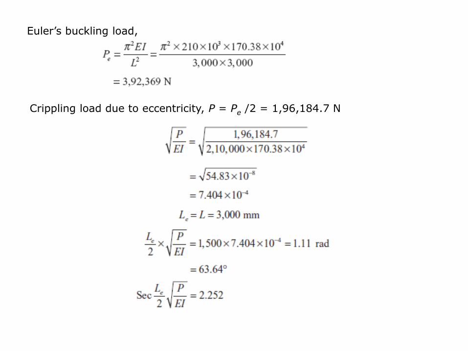
Euler’s buckling load,
Crippling load due to eccentricity, P = Pe /2 = 1,96,184.7 N
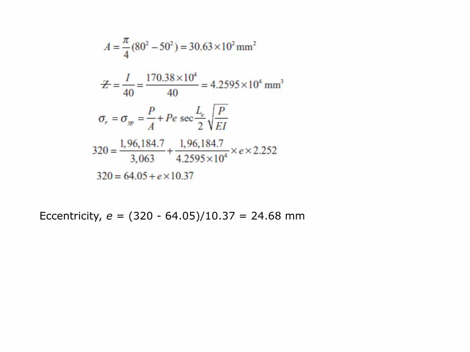
Eccentricity, e = (320 - 64.05)/10.37 = 24.68 mm

Long Columns with Eccentricity in Geometry
A column AB of length L with both the ends hinged has
an initial eccentricity e′ in the centre. Assuming deflection
curve to be sinusoidal (Figure 3),
eccentricity at any section,
Figure 3
e′ = maximum initial eccentricity at centre.
Taking a section at a distance of x from end A, let’s
consider the column buckled under load P.
Final deflection = y
Change in deflection = y-y′ (as shown)
BM at the section at a distance x from A as shown
′
′

as given
Putting this value in:

Let us assume the solution as
Putting this value in,
Putting the assumed value of y

However, p2EI/L2 = Pe, Euler’s buckling load
Finally, the deflection curve equation will be,

Maximum deflection occurs at the centre, where
Maximum bending moment,
σmax = maximum compressive stress at central section of column
where
k = radius of gyration
yc = distance of extreme layer
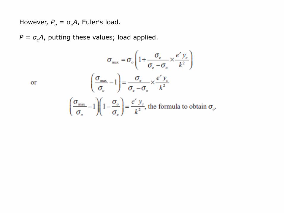
However, Pe = σeA, Euler’s load.
P = σeA, putting these values; load applied.

Example 9.10
A 5-m-long hollow circular steel strut having an outside diameter of 120 mm and
an inside diameter of 80 mm with both the ends hinged is initially bent. Assume
that the centre line of the strut as sinusoidal with maximum deviation of 6 mm.
Determine the maximum stress developed due to an axial load of 100 kN.
E = 210 kN/mm2
Length, L = 5 m
Eccentricity, e′ = 6 mm
Area of cross-section, A = (p /4)(1202 - 802) = 6283.2mm2
Moment of inertia, I = (p /64)(1204 — 804)
= 816.816 × 104 mm4
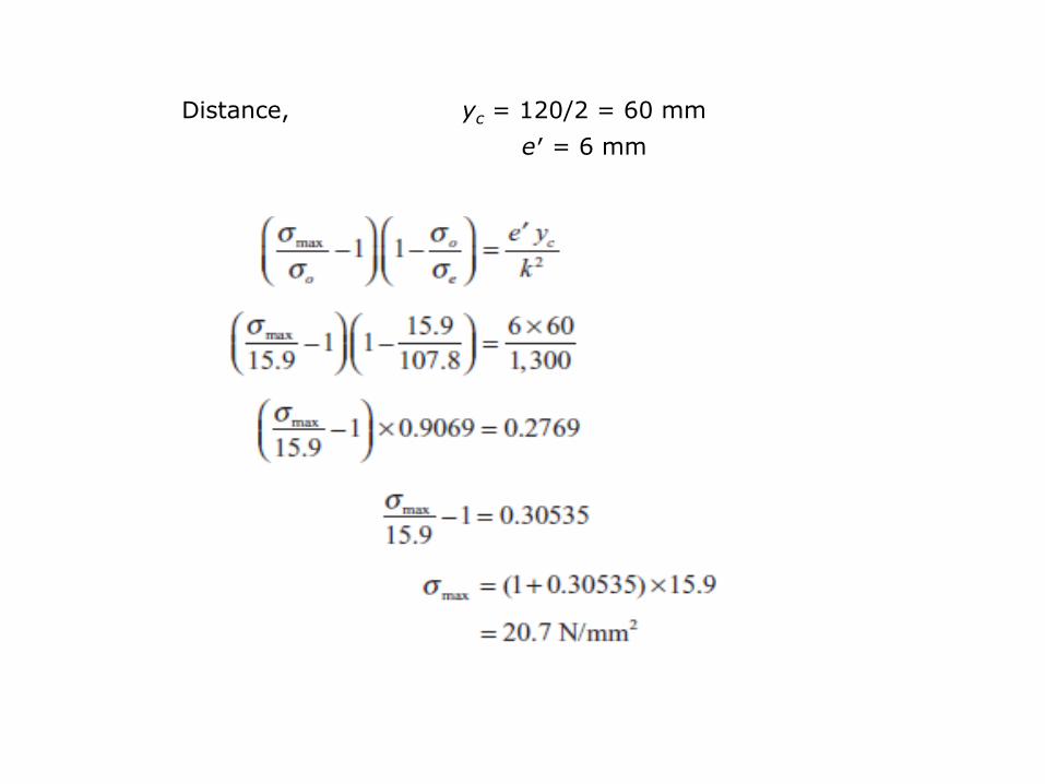
Distance, yc = 120/2 = 60 mm
e′ = 6 mm

Lateral Loading of Strut with Point Load
A strut or column may buckle under the combined action of axial thrust P and
transverse load (at centre) as shown in Figure 4. Lateral loading produces
deflection in the strut and axial thrust produces a bending moment on account of
deflection. The figure shows a column AB of length L, hinged at both the ends and
carrying a central transverse load W as shown. Due to W at C, there are
horizontal support reactions, W / 2 each.
Consider a section at a distance x from end A
Bending moment at the section, M = −Py − (Wx/2) or
Figure 4 Lateral point load on a strut
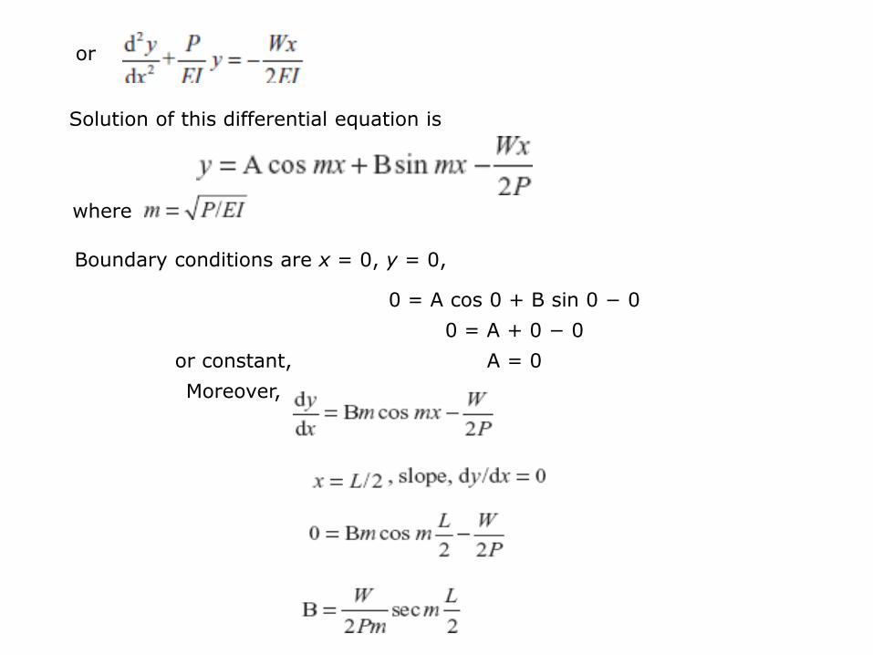
or
Solution of this differential equation is
where
Boundary conditions are x = 0, y = 0,
0 = A cos 0 + B sin 0 − 0
0 = A + 0 − 0
or constant, A = 0
Moreover,

Equation of deflection curve becomes
Maximum deflection occurs at centre at x = L/2
Maximum bending moment occurs at the centre, x = L / 2

putting the value of m
yc = distance of extreme layer in compression from neutral layer
or,

Example 9.11
A 4-m-long horizontal pin-ended strut is formed from a standard T-section of 150
mm × 100 mm × 12.5 mm. The axial compressive load is 60 kN. A lateral
concentrated load of 6 kN acts at the centre of the strut. Find the maximum stress
developed if the xx axis is horizontal and the table of the T-section forms the
compressive face. The centre of gravity is 24 mm away from the edge of the
table.
Given Ixx = 250 × 104 mm4, A = 3,100 mm2, E = 200 GPa

Axial load, P = 60 kN
Lateral load, W = 6 kN
Ixx = 250 × 104 mm2
A = 3,100 mm2
Length, L = 4 m
T-section, yc = 24 mm


Strut with a Uniformly Distributed Lateral Load
A strut subjected to axial thrust P and lateral load w per unit length is shown in
Figure 5. The length of the strut is L and it is hinged at both the ends A and B.
Consider a section at a distance x from end A. The bending moment at the
section,
Figure 5
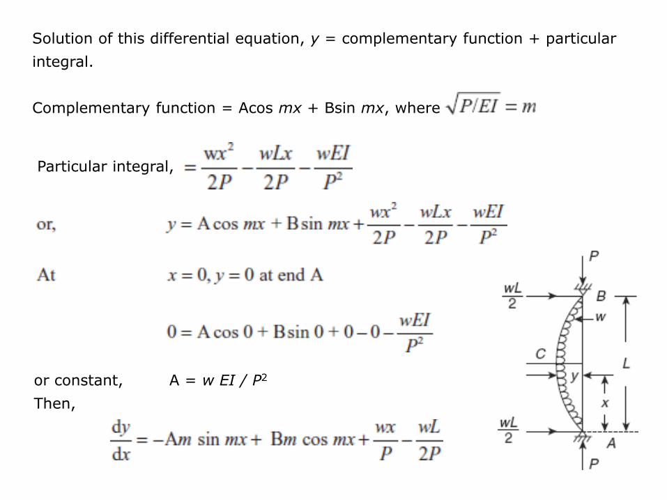
Solution of this differential equation, y = complementary function + particular
integral.
Complementary function = Acos mx + Bsin mx, where
Particular integral,
or constant, A = w EI / P2
Then,

dy/dx = 0 at x = L/2, at the centre of the beam due to symmetrical loading about
centre C,
However, A = w EI / P2
So constant,
Finally, the equation of y

At the centre, deflection is maximum, therefore, taking
Bending moment at the centre,

Maximum stress,
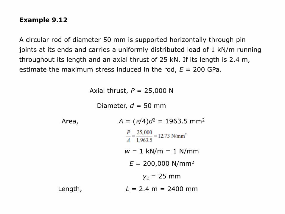
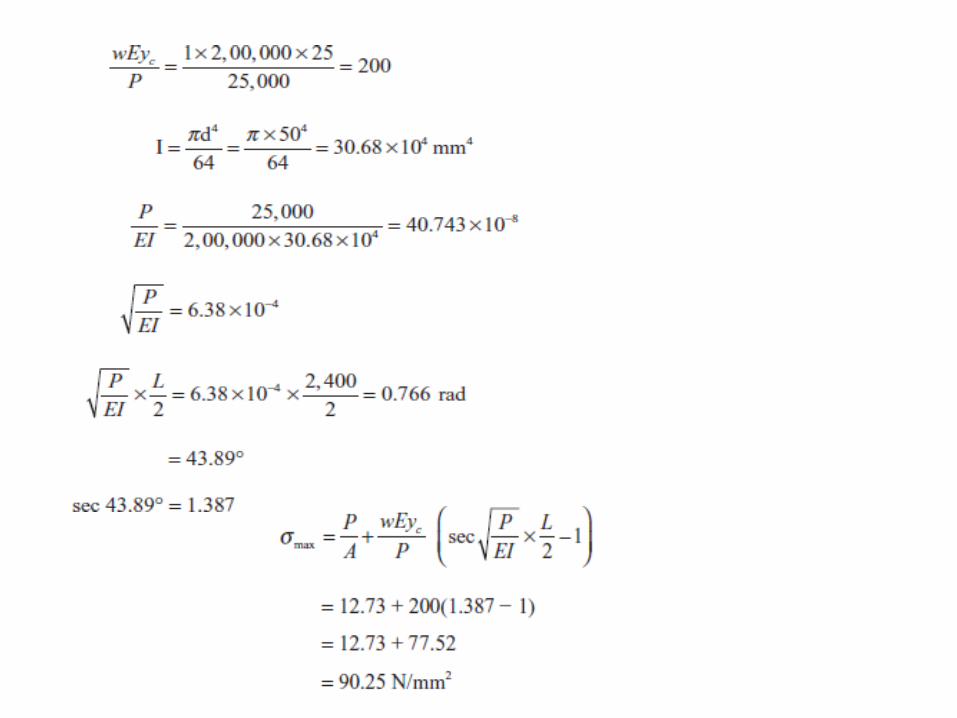
Example 9.12
A circular rod of diameter 50 mm is supported horizontally through pin
joints at its ends and carries a uniformly distributed load of 1 kN/m running
throughout its length and an axial thrust of 25 kN. If its length is 2.4 m,
estimate the maximum stress induced in the rod, E = 200 GPa.
Axial thrust, P = 25,000 N
Diameter, d = 50 mm
Area, A = (p/4)d2 = 1963.5 mm2
w = 1 kN/m = 1 N/mm
E = 200,000 N/mm2
yc = 25 mm
Length, L = 2.4 m = 2400 mm

Energy Approach
To determine the critical load at which a column ceases to be in a stable
equilibrium, energy criterion can be used. Moreover, in a situation where the exact
solution of a differential equation is not possible or difficult to obtain, energy
approach can be used to get a good approximate solution. However, this approach
converges to the exact solution if a large number of terms are taken to represent
the deflection curve.
Energy stored in a system = work done by external loads
δU + δVe = 0
δVe = external work done due to virtual displacement.
δ(U+Ve) = 0
δ(Kp) = 0
U + Ve = Kp = a constant referred to as the total potential of the system.

Energy stored,
External work done,
For small values of P, Kp is positive for any non-trivial admissible function y(x).
The critical load can be obtained by assuming suitable admissible function.
Critical condition is reached when constant Kp = 0
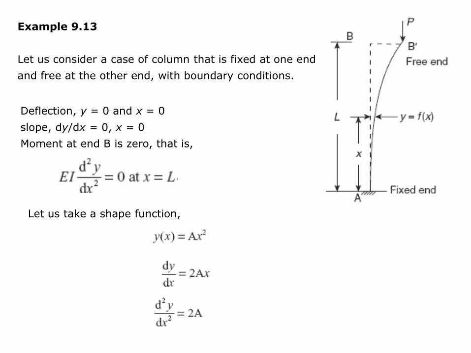
Example 9.13
Let us consider a case of column that is fixed at one end
and free at the other end, with boundary conditions.
Deflection, y = 0 and x = 0
slope, dy/dx = 0, x = 0
Moment at end B is zero, that is,
Let us take a shape function,
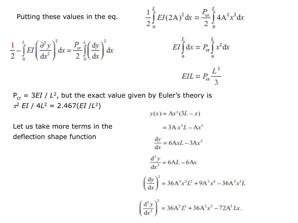
Putting these values in the eq.
Pcr = 3EI / L2, but the exact value given by Euler’s theory is
p2 EI / 4L2 = 2.467(EI /L2)
Let us take more terms in the
deflection shape function

Putting these values in the equation of total potential Kp,

Example 9.14
A long strut AB of length L is of uniform section throughout. A thrust P is applied
at the ends eccentrically on the same side of the centre line with eccentricity at
the end B twice than that at end A. Show that the maximum bending moment
occurs at a distance x from end A, where
The strut is buckled under the thrust load P.
P at two ends produce a couple P(2e − e) (cw)
that is to be balanced by anticlockwise couple
of horizontal reactions F each at A and B, as
shown F × L (ccw).

Force F is unknown. so 2Pe − Pe − FL = 0 or,
Consider a section at a distance x from end A,
Bending moment at the section (considering top part),
M = –P(2e + y) + F(L – x) or
Solution of this differential equation is,
where A and B are constants, and
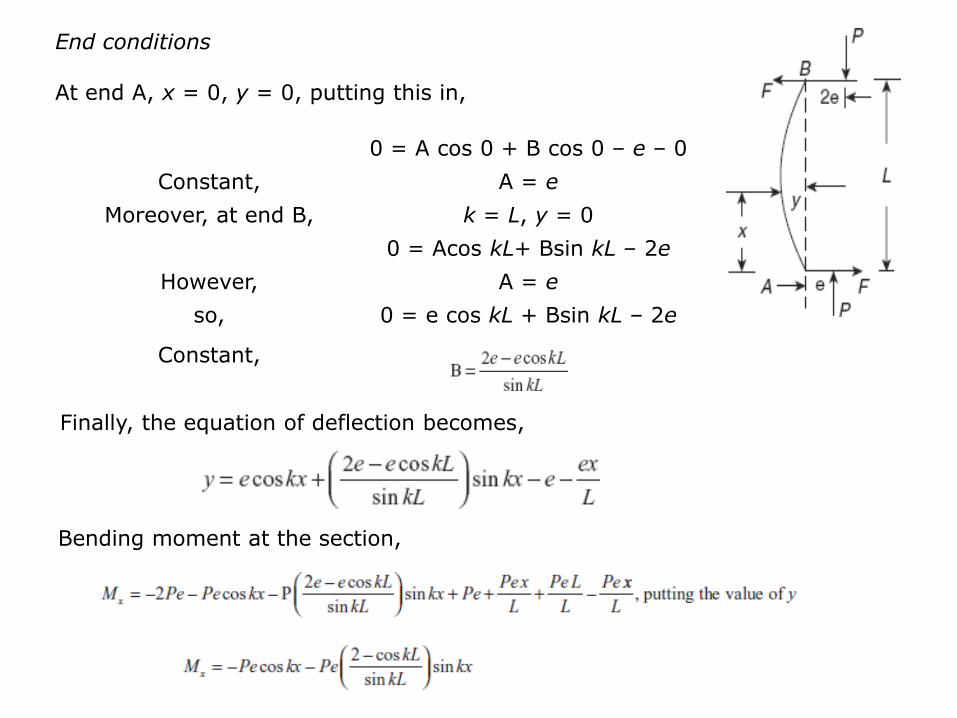
End conditions
At end A, x = 0, y = 0, putting this in,
0 = A cos 0 + B cos 0 – e – 0
Constant, A = e
Moreover, at end B, k = L, y = 0
0 = Acos kL+ Bsin kL – 2e
However, A = e
so, 0 = e cos kL + Bsin kL – 2e
Constant,
Finally, the equation of deflection becomes,
Bending moment at the section,

For maximum bending moment, dMx /dx = 0

Example 9.15
A strut of length L is fixed at its lower end, its upper end is eccentrically
supported against a lateral deflection (through a spring), so that the resisting
force is k times the end deflection, k is the spring constant. Show that the
crippling load P is given by 1 – (P/kL) = tan mL/mL.
where, .
The figure shows a strut AB of length L, fixed at
end A and free at end B. At the end B, the
horizontal reaction is H = ka, given by a spring
and P is the crippling load. Consider a section, at
a distance x from end A.
Bending moment at the section (top part),
M = P(a − y) − ka(L − x)

Solution of the differential equation
At end A, fixed end, x = 0, y = 0
Then,
or constant, B = –(ka/mP)
Finally, the equation of deflection curve is

At the end B,
or