structured grid motif
TRANSCRIPT

1
238
Applying finite difference methods to PDEs on
structured grids produces stencil operators that
must be applied to all points in the discretized grid
Challenged by bandwidth, temporal reuse, efficient
SIMD, etc… but trivial to (correctly) parallelize
Most optimizations can be independently
implemented
– Not performance independent
Core (cache) blocking and cache bypass were
clearly integral to performance
Structured Grid Motif
239
• Adaptive meshes
• Refinement done by estimating errors
• Refine mesh if too large
• Parallelism
• Mostly between “patches” assigned to
processors for load balance
• May exploit parallelism within a patch
Adaptive Mesh Refinement

2
240 Challenges of Irregular
Meshes How to generate them in the first place
– Start from geometric description of object
– Triangle – a 2D mesh partitioner
– 3D is significantly harder
How to partition them
– ParMetis – a parallel graph partitioner
How to design iterative solvers
– PETSc – a Portable Extensible Toolkit for Scientific Computing
– Prometheus – a multigrid solver for finite element problems on
irregular meshes
How to design direct solvers
– SuperLU – parallel sparse Gaussian elimination
These are challenges to do sequentially, more so in parallel
241
LBMHD simulates charged plasmas in a magnetic field (MHD) via Latice
Boltzmann Method (LBM) applied to CFD and Maxwell’s equations
To monitor density, momentum, and magnetic field, it requires maintaining two
“velocity” distributions – 27 (scalar) element velocity distribution for momentum
– 15 (Cartesian) element velocity distribution for magnetic field
– 632 bytes / grid point / time step
Jacobi‐like time evolution requires ~1300 flops and ~1200 bytes of memory traffic
Latice Boltzmann Methods

3
242
Distributed Memory & Hybrid
– MPI, MPI+pthreads, MPI+OpenMP
(SPMD, SPMD2, SPMD+Fork/Join)
For this large problem auto‐tuning
flat MPI delivered a significant
boost (2.5x)
Extending auto‐tuning to include
the domain decomposition and
balance between threads and
processes provided an extra 17%
2 processes with 2 threads was
best
– True for Pthreads and OpenMP
Latice Boltzmann Methods
Parallelization & Performance
243
Rather than calculating O(N2) forces, calculate impact of particles on
field and field on particles → O(N)
– Particle‐to‐grid interpolation (scatter‐add) – the most challenging step
– Poisson solver
– Grid‐to‐particle/push interpolation (gather) – EP
Used in a number of simulations including Heart and Fusion
Trivial simplification would be a 2D histogram
These codes can be challenging to parallelize in shared memory
Particle Method Motif –
Particle-in-Cell

4
245
Alternate (tree‐based) approach for calculating forces
Kernel Independent FMM (KIFMM) is challenged by 7 computational
phases (kernels) including list computations and tree traversals
List computations vary from those requiring direct particle‐particle
interactions to those based on many small FFTs
Different architectures (CPUs, GPUs…) may require different codes for
each phase
FMM is parameterized by the number of particles per box in the octtree – More particles/box → more flops (direct calculations)
– Fewer particle/box → fewer flops (but more work in tree traversals)
Fast Multipole Method
246
Different architectures showed speedups for different phases
from conventional auto‐tuning
Tuning algorithmic parameters showed different architectures
preferred different sweet spot:
– Nehalem’s sweet spot was around 250 particles/box
– GPUs required up to 4000 particles/box to attain similar performance: cope
with poor tree traversal performance GPU’s had to perform 16x as many flop’s
Fast Multipole Method (2)

5
247
Different architectures showed speedups for different phases
from conventional auto‐tuning
Tuning algorithmic parameters showed different architectures
preferred different sweet spot:
– Nehalem’s sweet spot was around 250 particles/box
– GPUs required up to 4000 particles/box to attain similar performance: cope
with poor tree traversal performance GPU’s had to perform 16x as many flop’s
Fast Multipole Method (3)
248
“Design spaces” for algorithms and
implementations are large and growing
Finding the best algorithm/implementation by
hand is hard and getting harder
Ideally, we would have a database of
“techniques” that would grow over time
– Search automatically whenever a new input
and/or machine comes along
Still lots of work to do…
Motifs Summary

6
249
Gedae
– Bring multicore processing to the masses
by automating the implementation of
software for multiprocessor and multicore
systems
Heterogeneous architectures
FPGAs
RapidMind (Intel)
– Portable software development platform for
multi-core and many-core processors
Rapid Prototyping Platforms
250
SW / HW System
Gedae SDK Component’s
Threaded
Application
Hardware
Model
Compiler
Implementation
Specification
Functional
Model
Developer
Analysis Tools
New
Language
Specification
Tools
Thread Manager
7
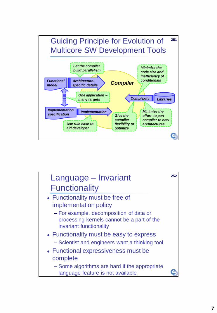
251
Compiler
Guiding Principle for Evolution of
Multicore SW Development Tools
Functional
model
Architecture-
specific details
Libraries
Implementation
specification Implementation
Complexity
Let the compiler
build parallelism Minimize the
code size and
inefficiency of
conditionals
Use rule base to
aid developer
One application –
many targets
Give the
compiler
flexibility to
optimize.
Minimize the
effort to port
compiler to new
architectures.
252 Language – Invariant
Functionality Functionality must be free of
implementation policy
– For example. decomposition of data or
processing kernels cannot be a part of the
invariant functionality
Functionality must be easy to express
– Scientist and engineers want a thinking tool
Functional expressiveness must be
complete
– Some algorithms are hard if the appropriate
language feature is not available

8
253
Language Features for Expressiveness
and Invariant Functionality
Stream data (time based data) *
Segmented streams with software reset on
segment boundaries *
Persistent data – state* extends to databases ‡
Algebraic equations (HLL most similar to
Mathcad) ‡
Conditionals †
Iteration ‡
State behavior †
Procedural * * These are mature language features
† These are currently directly supported in the language but will continue to evolve
‡ Support for directly expressing these behaviors. while possible to implement in the current product. will be added to the
language and compiler in a release later this year.
255
Language – Block Diagram

9
256 Language – Symbolic
Expressions
out[i][j](t) = sar(in[i][j](t). Taylor[j].
Azker[i*2]) {
range i2=2*size(i)
t1[i][j] = Taylor[j] * in[i][j]
range[i] = fft(t1[i])
cturn[j][i] = range[i][j]
adjoin[j][i2](t) = i2 < R ? cturn[j][i2](t) :
cturn[j][i2](t-1)
t2[j] = ifft(adjoin[j])
t3[j][i2] = Azker[i2] * t2[j][i2]
azimuth[j] = fft(t3[j])
out[j][i] = azimuth[j][i]
}
257 Language for Specifying
Dynamic Behavior Gedae’s data flow language features are
ideal for automatic resource allocation
– Load balancing
– Fault tolerance control
Resource allocation can be controlled
based on:
– Priority
– Latency requirements
– Temperature
– Power
– Balancing load

10
258 Implementation Tools – Summary of
Implementation Tools
Select from
4 memory
packers
Select whether to
prototype application
in SDK or as
separate executables
View the
hardware model
Automate setting
of queue sizes
between
dynamically
related threads
Implementation
tools for every
aspect of the
software
Select location
of command
program
Choose structure
of product View compiler
status
259 Implementation Tools –
Partitioning Tool
Tabular listing of all
functional components
in system
Equation based
partitioning of set of
functional components
Hierarchical partitioning

11
260 Implementation Tools – IPC
Specification Tool
Set the buffer size if
there is a buffer
associated with the
transfer mechanism
Gedae reports the source and
destination logical processor #s
Set the transfer type
from those specified in
the embedded
configuration file
Set the number of send
and receive buffers for
multi-buffering
Hierarchical list of data transfers between
partitions required to implement flow graph
261
Analysis Tools – Execution Trace
One application –
many targets
One application –
many targets
One application –
many targets
Summary by
processing core
Details by software
component

12
262 Analysis Tools – Event and
Processor Statistics
Detailed events and
events statistics are
available
Detailed events and
events statistics are
available
Detailed events and
events statistics are
available
263 Analysis Tools – Interprocessor
Communications Trace
Red and green are
sends and receives for
inter-processor and
inter-memory transfers

13
264 Analysis Tools – Distributed
Debugging
Processor controlled
individually or global stop
Gedae instruments code
with more or less detail
User can
add events
Breakpoints can be added on
any sensible event – like the 4th
firing of the FFT on partition p2
Probes can be added at
any point in
265
Analysis Tools – Memory Map
Every data
structure in
memory is
preplanned.
Black gaps are a
result of memory
alignment
requirements

14
266 Hardware Model – Components
that Affect Software Structure
Memory – Hierarchical – local store or cache
– Distributed
Processors / Processing Cores – Working definition is that each core has it own instruction
stream Fits the decomposition of the problem:
Getting the data into out of fast memory
Processing it efficiently when in fast memory
Interconnect between memories and processors – Characterization memory layout and buffer sizes required
for efficiency
Optimized vector functions – Characterization of memory layout required for efficiency
267 Hardware Model – Example
Architecture
Core
Core
Processor set
LS
SYSMEM Bridge
Processor set
SYSMEM
IPC IPC
Duplicate or
heterogeneous
Subsystems
Core Bridge
Core
LS
Core
LS
Core
LS
Core
LS
Core
LS
Core
LS
Core
LS

15
268
Compiler
A multithreading compiler
– Verification
– Buffer definition
– Thread definition
– Thread decomposition for distribution
– Add distribution infrastructure
– Concurrency control
– Deadlock avoidance
– Memory sharing among threads
– Memory optimization within threads
Product creation
– Function library
– Standalone executable
269
Verification
Gedae applications are correct by construction
Gedae constructs the distributed implementation so
that it is functionally equivalent to the single
processor implementation
Issues addressed include
– Ordering sends and receives so that deadlock is avoided
when using blocking transfers
– Ensuring the gains from interpolation/decimation are
equivalent when multiple arcs meet together
– Runtime queue resizing to detect blocking due to
dynamic and variable threshold queues

16
270 Automated Memory Planning
and Packing
Gedae uses data dependency
and locality to plan memory use
and primitive order of execution
All memory allocation is static
High reuse of buffers (packing)
Kernel
1
Kernel
2
Kernel
4 Kernel
3
B
A
1
2
C
3
4
S
Ord
er
of
Execu
tio
n
Kernel
Src A
Kernel
Src B
Kernel
Src C
Kernel
Sink
Memory
271
Supported Platforms
Workstations
– Intel x86. SPARC. PowerPC
Multicores
– Cell/B.E. processor
– Intel Core 2 with SSE3
– Blue Gene
– Freescale (Coming Soon)
DSPs
– PowerPC AltiVec
– TigerSHARC
Custom hardware through the BSP Development Kit
FPGAs and GPUs (Future)

17
272
Gedae Simulation
Gedae has a simulation tool that allows for
hardware software co-simulation
Hardware model is built using the same
development environment as software
– Model software running on hardware
– Model physical characteristics of hardware – temperature,
power, etc.
Report in trace table
– Model external systems
People
Planes
Physics (e.g. RADAR environmental simulator)
273
Gedae Simulation - Example Software functionality and hardware simulation
and run in Gedae simulation and connect just like
software connecting to target hardware
Hardware, OS and
system software all
must be modeled.
IPC HW and SW is
modeled including the
feedback between
sender and receiver

18
274
Gedae Simulation - Example
Hardware events like
data transfers OS and system software
events like initiating IPC
Application software events like
FFTs and vector multiplies
275
Gedae Roadmap
Symbolic Expression language
– Specification of programs as expressions
– Automated decomposition for data parallelism
– Equivalent to flow graph language, but entirely
textual
Data Analysis and Display (plots, images,
3-d, etc.)
19
276
Gedae Roadmap
Code overlays
– Increased program size
– Improving startup time Status shown in table – times in uSec
– Support very complex overlay schemes
– All the data movement tools in Gedae apply
Stage (8 SPEs) Initial Current Future
Range ~100,000 989 80
Corner Turn ~100,000 628 80
Azimuth ~100,000 702 80
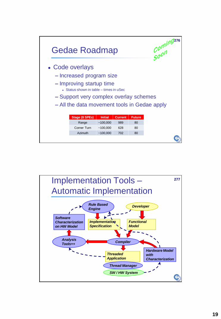
277 Implementation Tools –
Automatic Implementation
Threaded
Application
Hardware Model
with
Characterization
Compiler
Functional
Model
Rule Based
Engine
Analysis
Tools++
Software
Characterization
on HW Model
Developer
Implementation
Specification
SW / HW System
Thread Manager

20
278 Software Architecture
Recommendations / Templates
Automatic implementation that is being
introduced will contain knowledge about
software architecture for various software /
hardware systems
Gedae is introducing a software and
hardware characterization tool
– Raw data already available in trace collection
– Full characterization of hardware
– Full characterization of software on hardware
279 Cell/B.E. Benchmark Results -
Summary
Monte Carlo Black-Scholes Simulation
– Same as performance of hand optimized code
Matrix multiply
– Block data layout
– 194 gflops – 95% of theoretical max
SAR (synthetic aperture RADAR)
– End to end timing including 0 flop cornerturn
– Sustained 88 gflops/sec
– 87x algorithm on a 500 Mhz quad altivec
board (normalized clock speed – 13.6 x)

21
280
Portable software development platform for multi-
core and many-core processors
Single-source solution for portable, high-
performance parallel programming
Supports high productivity development
Safe and deterministic general-purpose structured
programming model (SPMD stream)
Scalable to an arbitrary number of cores
Can be used to target both accelerators and
multicore processors
Integrates with existing C++ compilers
RapidMind Platform
281
RapidMind Platform (2)

22
282
A good programming technology should:
1. Provide an accurate conceptual model of the
hardware
2. Clearly expose the most important policy
decisions and architectural elements of the
hardware
3. Provide structure and modularity
4. Automate what can be automated, and not
overload the programmer with trivia
5. Provide drill-down mechanisms for use when
necessary
High Productivity Parallel
Programming
283
Usage
– Include platform header
– Link to runtime library
Data
– Values
– Arrays
– Data abstraction
Programs
– Defined dynamically
– Execute on
coprocessors
– Code abstraction
RapidMind Summary
#include <rapidmind/platform.hpp>
using namespace rapidmind;
Value1f f = 2.0f;
Array<2,Value3f> a(512,512);
Array<2,Value3f> b(512,512);
Program prog = BEGIN {
In<Value3f> r, s;
Out<Value3f> q;
q = (r + s) * f;
} END;
a = prog(a,b);
f = 3.0f;
stride(a,2,2) = prog(
slice(a,0,255,0,255),
slice(b,256,511,0,255));

23
284
RapidMind Examples
Fluid Simulation
Crowd Simulation
285
Multi-core/Many-core is a major disruption
– All computers will be massively parallel
– All programmers will have to write parallel programs
– Focus will be on developers to scale performance
– Software development challenge
Programming models are important!
– Threading difficult, unsafe, and has poor scalability
– Structured parallelism has scalability and safety advantages
– Want system to compose multiple deterministic patterns
Programming platforms:
– Not necessary to introduce completely new languages
– Can obtain similar performance and expressiveness within standard
C++ and existing compilers
Prototyping Platforms
Conclusions