structure solutions from powder x-ray diffraction
TRANSCRIPT

Structure Solutions from Powder X-ray Diffraction
1

Welcome
Structure Determination with TOPAS -OverviewMethods of Solution• Simulated Annealing• Charge Flipping• 3D Fourier Analysis• Simulated Annealing vs. Charge
Flipping
Data Quality Issues• Instrument Considerations• Variable Counting Time
Conclusions
Arnt KernProduct Manager XRD
Heiko RessMarketing Manager US

Structure determination with TOPAS -Overview
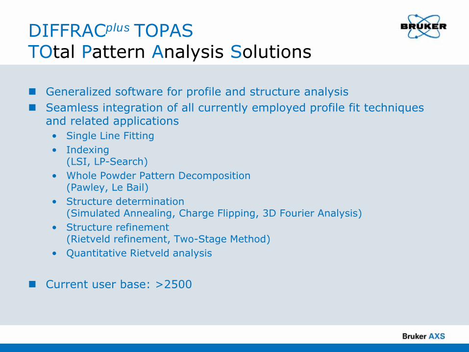
DIFFRACplus TOPASTOtal Pattern Analysis Solutions
Generalized software for profile and structure analysisSeamless integration of all currently employed profile fit techniques and related applications• Single Line Fitting• Indexing
(LSI, LP-Search)• Whole Powder Pattern Decomposition
(Pawley, Le Bail) • Structure determination
(Simulated Annealing, Charge Flipping, 3D Fourier Analysis)• Structure refinement
(Rietveld refinement, Two-Stage Method)• Quantitative Rietveld analysis
Current user base: >2500

The Classic SDPD Process
Intensity Extraction• Le Bail, Pawley
Structure Determination using F2(obs)Structure Refinement using yi(obs) or F2(obs)
Peak FindingIndexing
F2(obs): Observed structure factorsyi(obs) : Observed step intensity dataStructure Refinement using F2(obs): Two-Stage Method (Will, 1979)Structure Refinement using yi(obs) : Rietveld method (Rietveld, 1967, 1969)

The Classic SDPD Process
Intensity Extraction• Le Bail, Pawley
Structure Determination using F2(obs)Structure Refinement using yi(obs) or F2(obs)
Peak FindingIndexing

SDPD Processes in TOPASF2(obs) or yi(obs)
Intensity Extraction• Le Bail, Pawley
Structure Determination using F2(obs)Structure Refinement using yi(obs) or F2(obs)
"Profiling"• Le Bail, Pawley
Structure Determination AND Refinementusing yi(obs)
Peak FindingIndexing
TOPAS ApproachCoelho (2000)
Suited for• Simulated annealing• Charge Flipping
Suited for• Simulated annealing

TOPASStructure Determination Features
Simultaneous refinement on any number of powder and single crystal data sets (lab and synchrotron X-ray data, CW and TOF neutron data)
• Refines on any number of structures per diffraction pattern. For a given multiphase pattern, all profile fitting techniques supported by TOPAS can be used simultaneously to describe individual phase contributions to the full pattern
• Structure determination in the presence of additional phase(s) with known or unknown structure
• Successful structure determination of 2 phases simultaneously (simulated annealing)Flexible macro language
• Support of user-defined refinement parameters / refinement models• Computer algebra system for function minimization and for the application of linear
and non-linear restraints
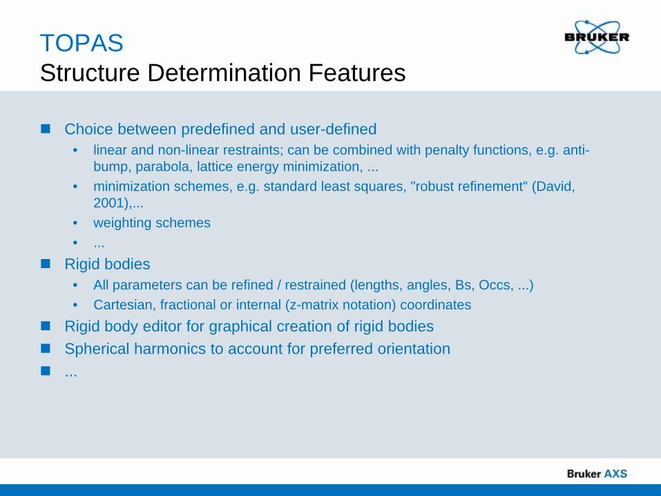
TOPASStructure Determination Features
Choice between predefined and user-defined • linear and non-linear restraints; can be combined with penalty functions, e.g. anti-
bump, parabola, lattice energy minimization, ...• minimization schemes, e.g. standard least squares, "robust refinement" (David,
2001),...• weighting schemes• ...
Rigid bodies • All parameters can be refined / restrained (lengths, angles, Bs, Occs, ...)• Cartesian, fractional or internal (z-matrix notation) coordinates
Rigid body editor for graphical creation of rigid bodiesSpherical harmonics to account for preferred orientation...
Simulated Annealing

Structure DeterminationSimulated Annealing
Simulated annealing is a direct space approach where adjustable parameters lie in direct rather than reciprocal spaceProcedure:1. A trial crystal structure is constructed by randomly positioning and
orienting individual atoms, molecular fragments or complete molecules taking into account (known or guessed) space group information
2. After calculating diffraction data and comparing it against the measured diffraction data, the variable parameters of the model are adjusted in order to maximise the level of agreement between the observed and calculated data (i.e., minimize χ2).
This procedure is typically applied to observed structure factors, F2(obs), but has been extended to step intensity data, yi(obs)
TOPAS (Coelho, 2000)

Classic Rietveld Method Definition (I)
Hugo M. Rietveld, 1967/1969The basic principle of the method is a description of all data points of a powder pattern using analytical functions The parameters of these functions, consisting of crystal structure, sample, instrument and background parameters, are refined simultaneously using least squares methods
( ) ( )[ ]∑ →−=i
iii calcyobsywChi min22

Classic Rietveld Method Definition (II)
Important Key Features:Step intensity data instead of structure factors, F2(obs), are used. Each data point is an observation. • No attempts are made to deconvolute overlapped peaks, avoiding problems
associated with intensity partitioning
A preconceived (at least partial) structure model is required, "with its parameters reasonably close enough to the final values"This automatically raises the question:
"How far off the position of an atom may be and the refinement still brings it in?"

TOPAS"Global Rietveld Refinement"
"A correctly formulated global optimisation approach may be regarded as a Global Rietveld Refinement"
(K. Shankland, 2004)
For step intensity powder data, repeated Rietveld refinements of trial structures are performed: after convergence a new Rietveld refinement is initiated with parameter values changed according to a temperature regime ( simulated annealing)Using step intensity data for structure determination has important and obvious advantages:• No preceeding intensity extraction required• No problems associated with peak overlap (intensity partitioning)• Structure determination from poor quality powder data

SDPDSpeed Matters...
Diffraction data types supported by TOPASStructure factors, F2(obs)• good data quality needed• single crystal data can be used• fast
Step intensity data• no preceeding intensity extraction required• avoids problems associated with peak overlap
(intensity partitioning)• structure solution from poor quality powder data• slow
"Peak maximum intensities"• step intensity data set comprising only data at calculated peak positions;
data in between are discarded• fast
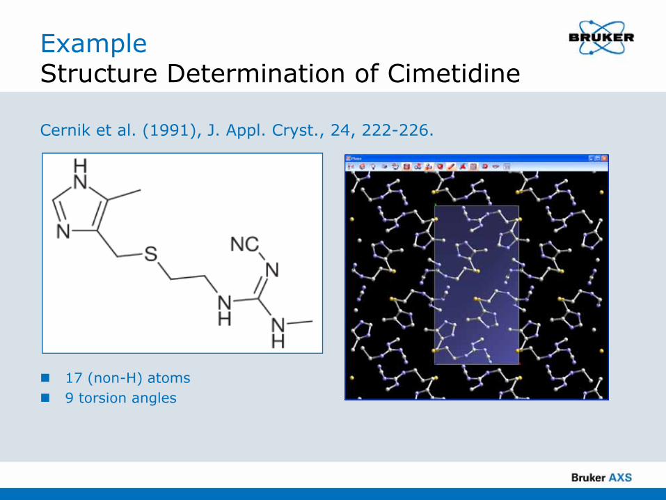
ExampleStructure Determination of Cimetidine
Cernik et al. (1991), J. Appl. Cryst., 24, 222-226.
17 (non-H) atoms9 torsion angles

From step intensity data to "peak maximum intensities"
ExampleStructure Determination of Cimetidine
~6 times faster

Example (1 GHz PIII, 250.000 iters)Structure Determination of Cimetidine
Individual atomsNr. of DoFs : 51Nr. of solutions: 11Time : 2090 sec.Success rate : 190 sec / solution
Individual atoms, S "boxed"Nr. of DoFs : 51Nr. of solutions: 29Time : 2118 sec.Success rate : 73 sec / solution
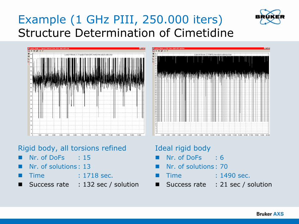
Example (1 GHz PIII, 250.000 iters)Structure Determination of Cimetidine
Rigid body, all torsions refinedNr. of DoFs : 15Nr. of solutions: 13Time : 1718 sec.Success rate : 132 sec / solution
Ideal rigid bodyNr. of DoFs : 6Nr. of solutions: 70Time : 1490 sec.Success rate : 21 sec / solution

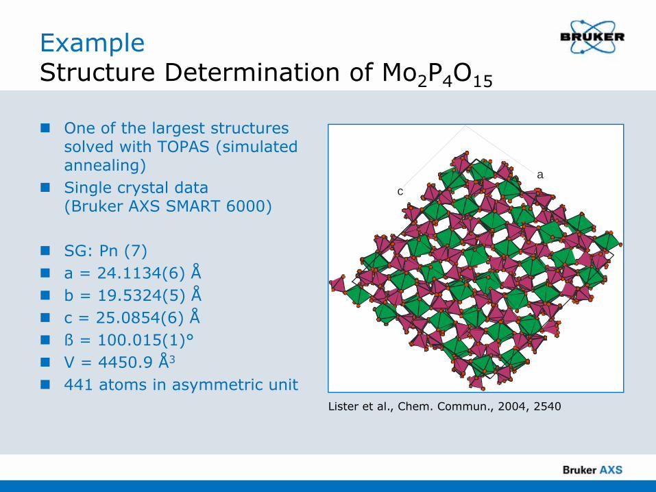
ExampleStructure Determination of Mo2P4O15
One of the largest structures solved with TOPAS (simulated annealing)Single crystal data (Bruker AXS SMART 6000)
SG: Pn (7) a = 24.1134(6) Åb = 19.5324(5) Åc = 25.0854(6) Åß = 100.015(1)°V = 4450.9 Å3
441 atoms in asymmetric unit
ac
Lister et al., Chem. Commun., 2004, 2540

Charge Flipping

Charge FlippingOszlányi and Sütő, 2004
Iterative algorithmRequires only lattice parameters and reflection intensitiesNo use of chemistry / trial structure modelsThe output is an approximate scattering density of the structure sampled on a discrete gridCharge flipping is very fast• The grid size determines the calculation speed
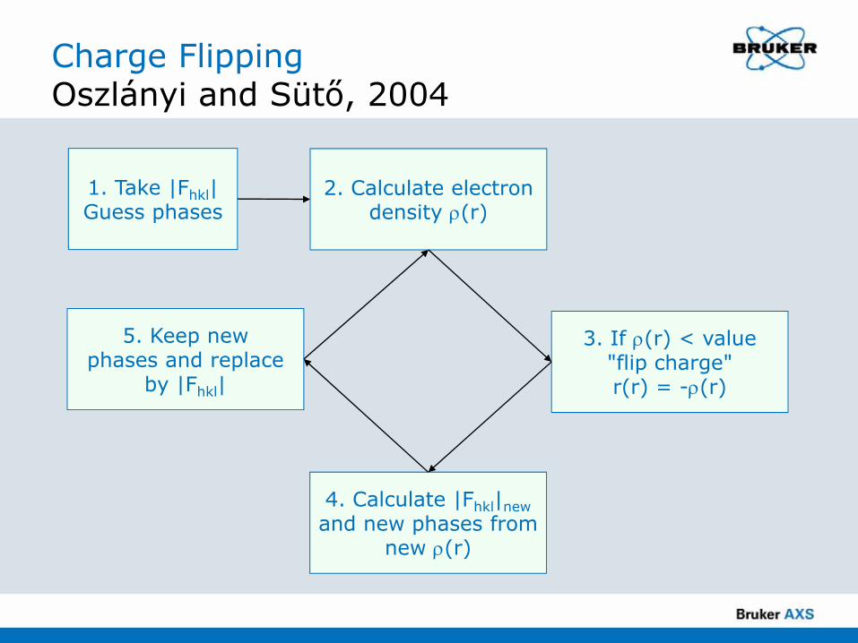
Charge FlippingOszlányi and Sütő, 2004
1. Take |Fhkl|Guess phases
2. Calculate electrondensity ρ(r)
3. If ρ(r) < value "flip charge"r(r) = -ρ(r)
4. Calculate |Fhkl|newand new phases from
new ρ(r)
5. Keep new phases and replace
by |Fhkl|

Charge Flipping Memory Lane
The beginning:Oszlányi and Sütő, Acta Cryst. (2004). A60, 134-141Superspace solutions:Palatinus, Acta Cryst. (2004). A60, 604-610Powder diffraction:Wu, Leinenweber, Spence & O'KeeffeNature Materials (2006). 5, 647 - 652Histogram matching:Baerlocher, McCusker and Palatinus, Z.Krist. (2007). 222 47-53Tangent formula, symmetry consideration, determination of origin, atom picking and assignment:Coelho, Acta Cryst. (2007), A36, 400–406
ExampleStructure Determination of Mo2P4O15
One of the largest structures solved with TOPAS (simulated annealing)Single crystal data (Bruker AXS SMART 6000)
SG: Pn (7) a = 24.1134(6) Åb = 19.5324(5) Åc = 25.0854(6) Åß = 100.015(1)°V = 4450.9 Å3
441 atoms in asymmetric unit
ac
Lister et al., Chem. Commun., 2004, 2540

ExampleStructure Determination of Mo2P4O15
Charge Flipping"Default" runTypically very high proportion of 441 atoms correctly identified (>99%?)
~15 sec.
3D Fourier Analysis
TOPAS3D Fourier Analysis
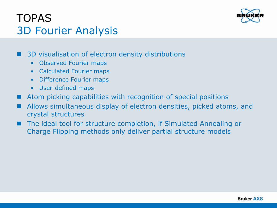
3D visualisation of electron density distributions • Observed Fourier maps• Calculated Fourier maps• Difference Fourier maps • User-defined maps
Atom picking capabilities with recognition of special positionsAllows simultaneous display of electron densities, picked atoms, and crystal structures The ideal tool for structure completion, if Simulated Annealing or Charge Flipping methods only deliver partial structure models

TOPAS3D Fourier Analysis
PbSO4
Difference Fourier analysis to locate missing oxygen positions
Final structure after atom picking

Simulated Annealing vs. Charge Flipping

http://www.cristal.org/SDPDRR3/index.html
3rd SDPD Round RobinSDPDRR-3

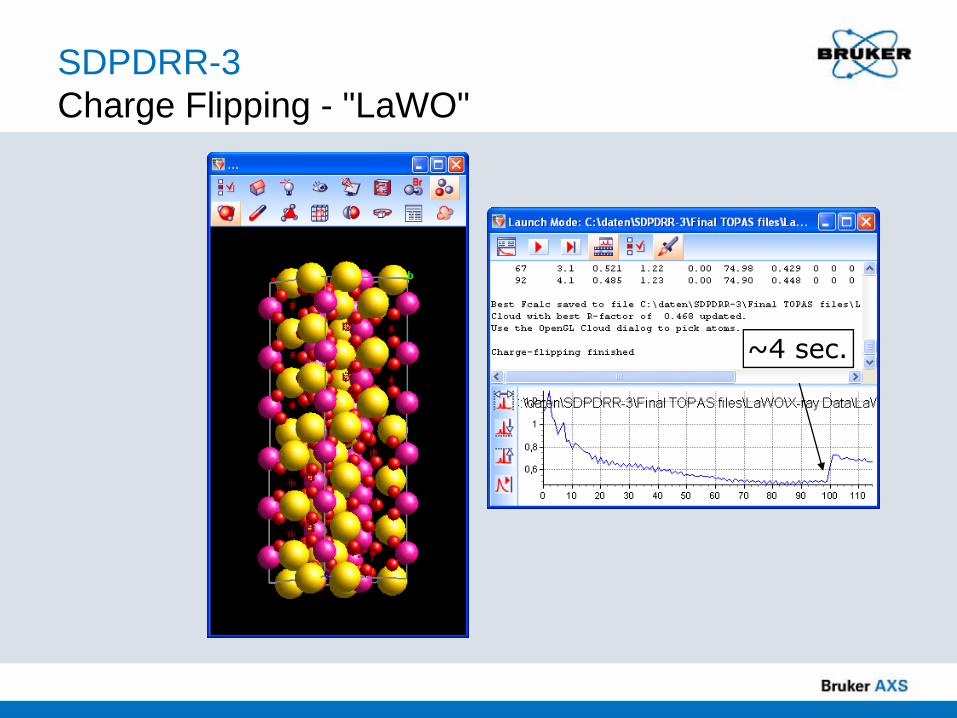
SDPDRR-3Charge Flipping - "LaWO"
SDPDRR-3, sample 2:
Sample info provided:Probable formula close to La14W8O45 or La8W5O27
Symmetry: hexagonala = 9.039 Å, c = from 32.60 to 33.65 Ådue to composition variation
Proposed solution (organizers):La18W10O57, Z = 2P-62c (No. 190)W6 half occupied site(very short W4-W6 interactomic distance 2.42 Å)
d~0.77Å

SDPDRR-3Charge Flipping - "LaWO"
~4 sec.
SDPDRR-3Charge Flipping - "LaWO"
~4 sec.

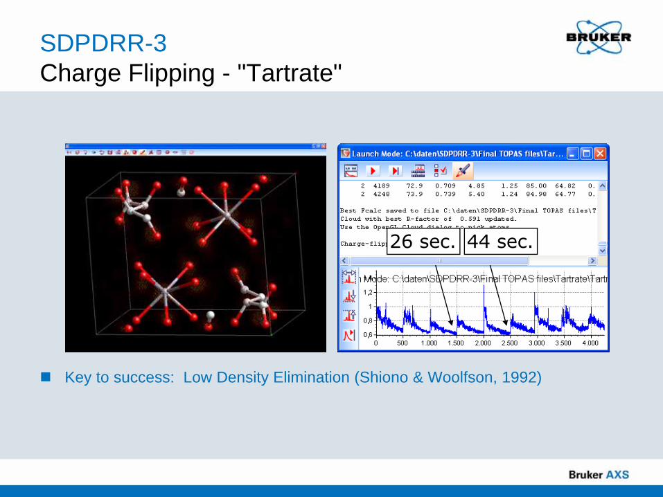
SDPDRR-3Charge Flipping - "Tartrate"
SDPDRR-3, sample 1:
Sample info provided:Probable formula: CaC4H4O6·4H2O Symmetry: Triclinic cell parameters: a = 8.222 Å, α = 105.97°b = 10.437 Å, β = 107.51°c = 6.249 Å, γ = 94.94°
Proposed solution (organizers):CaC4H4O6·4H2O, Z = 2P-1 (No. 2)
d~1.30Å
March-Dollase PO(101): ~0.9(obtained from final Rietveld refinement)
Charge Flipping is successful here despitesignificant preferred orientation!

SDPDRR-3Charge Flipping - "Tartrate"
Key to success: Low Density Elimination (Shiono & Woolfson, 1992)
26 sec. 44 sec.
SDPDRR-3Charge Flipping - "Tartrate"
Key to success: Low Density Elimination (Shiono & Woolfson, 1992)
26 sec. 44 sec.

Simulated Annealing vs. Charge FlippingConclusions
Simulated Annealing: Requires a trial structure model, which can be partial or randomPerforms better on poor quality data. Important advantage!Comparatively slow
Charge Flipping:No use of chemistry / trial structure models. Important advantage!Requires high quality dataEven if the structure doesnt solve completely, heavy atoms and / or molecular fragments can often be found very quickly, which greatly assists subsequent simulated annealing structure determinationVery fast; structures can be (partially) solved in seconds up to a few minutes, i.e. faster than one typically can create a start model / rigid body for simulated annealing
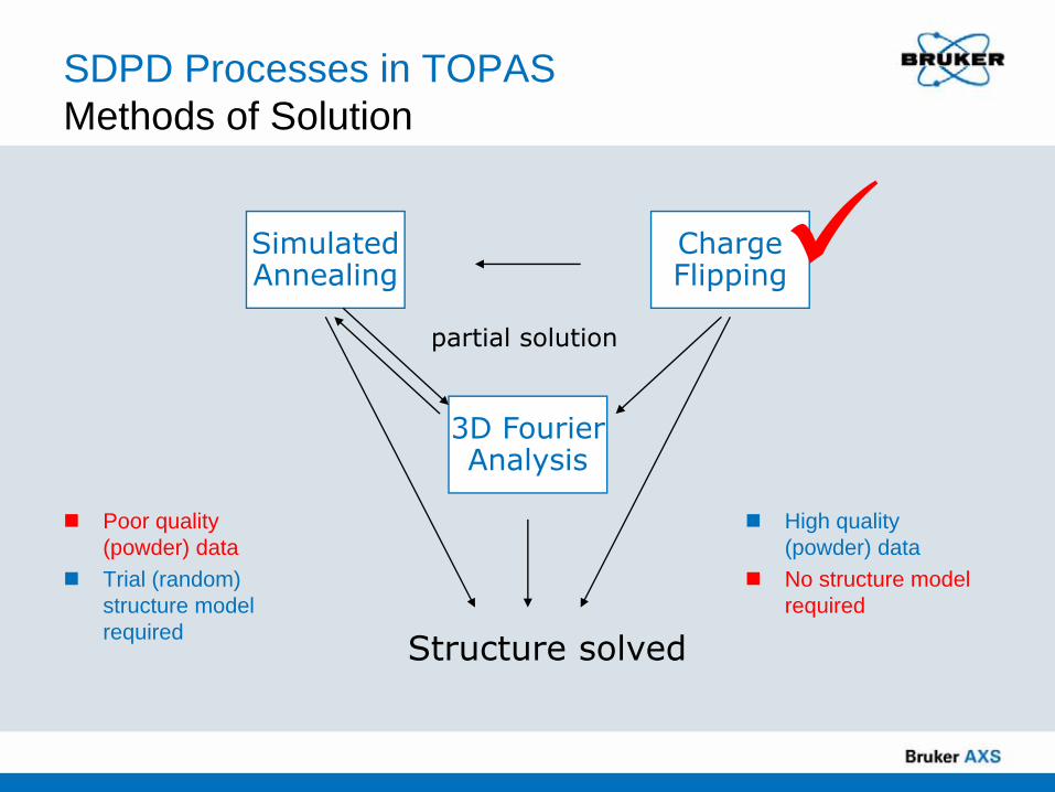
SDPD Processes in TOPASMethods of Solution
Poor quality (powder) dataTrial (random) structure model required
High quality (powder) dataNo structure model required
SimulatedAnnealing
ChargeFlipping
3D FourierAnalysis
Structure solved
partial solution
Data Quality Issues

The new D8 ADVANCE
The ideal machine for laboratory crystal structure and PDF analysis
SDPDInstrument Considerations
BenefitsTransmission setup to minimize preferred orientation effectsHigh-energy radiation (Mo, Ag) to minimize sample transparency effectsOne single instrument setup equally suited for both organic and inorganic materials
Range of options:Cu-, Mo-, and Ag-radiationPrimary monochromators for pure Ka1radiation for all wavelengthsBoth parallel beam and focussing Göbel mirrors for high flux for all wavelengthsDedicated LYNXEYE detectors for all wavelengths
Primary monochromator
Capillary sample holder
LYNXEYE detector
Anti-scatter slits /beam stop

ExampleICN-SbF5
Mass absorption coefficients for ICN-SbF5:
• lCu: 189 cm2/g• lMo: 26 cm2/g • Cu-transmission geometry is not an option
for this material!
Cu mass absorption coefficients for some example materials:
• Al2O3 : 32 cm2/g• SiO2 : 36 cm2/g• PbSO4 : 167 cm2/g• Fe3O4 : 221 cm2/g
Dinnebier (2009)
D8 ADVANCE with capillary stage and LYNXEYE detector, Mo-radiationSample consists of 3 phases: Structure determination of ICN-SbF5 with simultaneous refinement of 2 additional phases via Le Bail and single line fitting, respectively

SDPDVariable Counting Time
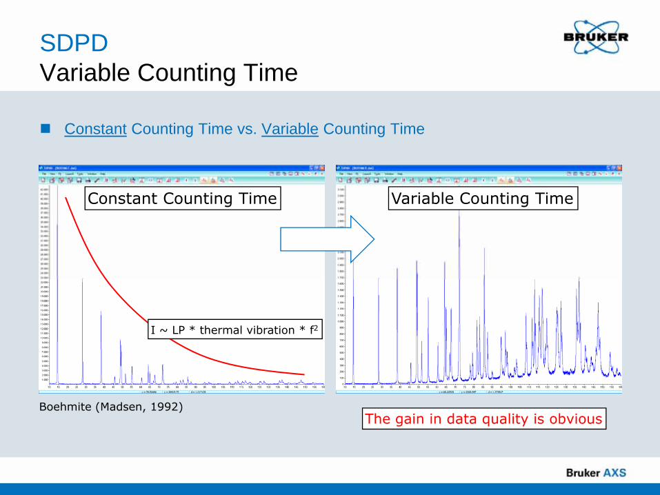
For X-ray diffraction, a number of factors act to progressively decrease the observed intensities as the Bragg angle increasesThe major factors causing this decrease are
• Lorentz-polarisation factor (LP)• Thermal vibration• Atomic scattering (f)
The fall in diffracted intensities can be larger than two orders of magnitudeacross the pattern
The goal: Collection and analysis of powder diffraction data with near-constant counting statistics (David, 1992; Madsen, 1992)
SDPDVariable Counting Time
Constant Counting Time vs. Variable Counting Time
Boehmite (Madsen, 1992)
Constant Counting Time Variable Counting Time
The gain in data quality is obvious
I ~ LP * thermal vibration * f2
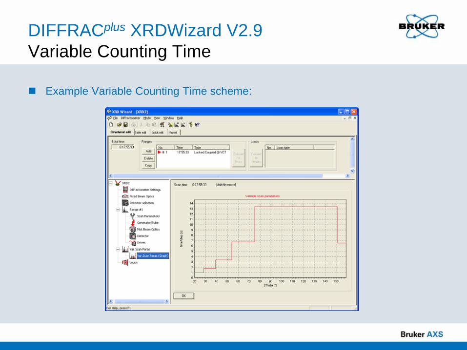
DIFFRACplus XRDWizard V2.9 Variable Counting Time
Example Variable Counting Time scheme:

SDPDVariable Counting Time
A VCT strategy can greatly enhance the chances of success of SDPD but has always significant benefits for structure refinementAtomic coordinates, occupancy factors and (anisotropic) thermal parameters are better determined, especially in the case of light atomsRefinement of atomic coordinates and thermal parameters of very light atoms, is more likely to be stable with VCT

Conclusions
ConclusionsStructure Determination with TOPAS
Structure determination using direct space and charge flipping methods can be considered routine for many powder diffraction problems as emphasised by the significant increase in the number of published structures solved in this wayThe major limitions are related to the well known ambiguities related to systematic and accidental peak overlap in powder diffraction. Profound crystallographic knowledge is required to deal with these limitations.
• The maximum size of structures that can be solved with TOPAS is thus mainly limited by data quality
Charge Flipping is generally suggested to start with from the beginning due to its ease of use and speed. Chances are high to find at least a partial solution, which may then greatly assist to create a better trial structure for subsequent Simulated Annealing runs.

Any Questions?
Please type any questions you may have in the Q&A panel and then
click Send.
49
Getting Started with TOPASlive online training course
Dec 15 and 16, 2009 11:00 AM – 12:30 PM CST (US)(two 90-minute sessions)
Purchase and register all in one step under the Training section at
www.brukersupport.com
To Learn More About Structure Determination
50

Bruker Confidential 10/2/2009Bruker Confidential51
… think forward
Completely automated operationStructure information when you need itQuick, reliable and effectiveBenchtop system designed for synthetic chemistsjoin contest today: http://www.bruker-axs.com
SMART X2S:Automated chemical crystallography solution
Bruker Confidential
Thank you for attending!
Please take a moment to complete the brief survey on your screen. Your feedback is very
important to us.
Copies of this presentation and related resource materials will be e-mailed to you.
52

Bruker Confidential53
www.bruker-axs.com
Visit us at:Gulf Coast Conference (GCC)
Oct 13-14, Galveston, TX
Geological Society of America (GSA)Oct 18-21, Portland, OR
Cement Chemists’ Society ConferenceOct 19-23, Orlando, FL
Pittsburgh Diffraction CongressOct 29-31, University of Georgia, Athens, GA
Buffalo-Hamilton-Toronto Symposium (BHT)Nov 6, Hamilton, ON
American Association of Pharmaceutical Scientists (AAPS)Nov 9-11, Los Angeles, CA
Materials Research Society (MRS Fall)Dec 1-3, Boston, MA

www.bruker-axs.com