structure selection report for colorado … selection report for . colorado center bicycle /...
TRANSCRIPT

STRUCTURE SELECTION REPORT
for
Colorado Center Bicycle / Pedestrian Bridge
Prepared for:
City and County of Denver
Submitted by:
1600 Broadway, Suite 1300
Denver, CO 80202
(303) 839-8300
Date: December 21, 2010
Revised: September 02, 2011

2
Table of Contents
PROJECT OVERVIEW ...................................................................................................................................... 4
Project Description.................................................................................................................................... 4
Site Location and Description ................................................................................................................... 5
PROJECT CRITERIA ......................................................................................................................................... 7
Structural Design Criteria .......................................................................................................................... 7
Construction Phasing and Methods .......................................................................................................... 7
Right-of-Way Considerations .................................................................................................................... 8
Hydraulics .................................................................................................................................................. 8
Geology Data ............................................................................................................................................. 8
Aesthetic Requirements ............................................................................................................................ 8
Lighting Requirements .............................................................................................................................. 8
Utilities .................................................................................................................................................... 10
Environmental Considerations ................................................................................................................ 10
Traffic Control ......................................................................................................................................... 10
Public Information .................................................................................................................................. 10
ALIGNMENT AND STRUCTURE TYPE ALTERNATIVES ................................................................................... 11
Alignment Alternatives ........................................................................................................................... 11
Structure Type Alternatives .................................................................................................................... 12
STRUCTURE TYPE ALTERNATIVES EVALUATION AND RECOMMENDATION ............................................... 14
Selection Criteria ..................................................................................................................................... 14
Estimate of Probable Construction Costs ............................................................................................... 14
Structure Recommendation .................................................................................................................... 15
3
APPENDICES
A. SITE MAPS AND PHOTOS B. PRELIMINARY STRUCTURE DESIGN CRITERIA C. UTILITIES D. PUBLIC MEETING MATERIALS (JULY 28, 2010) E. ALIGNMENT ALTERNATIVES F. RECOMMENDED ALIGNMENT G. MAIN SPAN STRUCTURE TYPE ALTERNATIVES (FOR RECOMMENDED ALIGNMENT) H. ESTIMATE OF PROBABLE CONSTRUCTION COSTS I. STRUCTURE TYPE ALTERNATIVES – SITE PLAN & DETAILS

4
PROJECT OVERVIEW
Project Description Currently the only bike/pedestrian access across I-25 near the Colorado Center is provided by sidewalks on both the Colorado Boulevard and Evans Avenue bridges. Both of these structures are at I-25 interchanges with high speeds and volumes of traffic that many people find daunting. The need for a bike/pedestrian bridge was discussed as far back as 1999 and was initially proposed as part of the Southeast Corridor (T-REX) project. Due to budget constraints the structure was eliminated from the T-REX project.
Shortly thereafter, the 2001 Denver Bicycle Master Plan identified connectivity across I-25 to the Colorado Center and RTD Light Rail Station as a major missing link in the bicycle system and proposed a pedestrian bridge across I-25 near S. Bellaire Street. This project seeks to provide that missing link.
The total project budget, including the costs of right-of-way acquisition, design, and construction, is $8 Million. The project is funded with $4 Million in 2010 City Capital Improvement Funds, and $4 Million in 2011 Federal Transportation Improvement Program (TIP) Funds. Security elements and potential aesthetic lighting of the structure are anticipated. The structure will have a horizontal deck clearance of 10 – 14 feet and horizontal deck clearance of 10 feet on the ramps approaching each end of the structure. Each ramp will also incorporate appropriate landscaping and lighting.
Final design is scheduled to be completed in the fall of 2011. Construction is scheduled to begin in 2012 with an anticipated construction schedule of one and a half to two years.
5
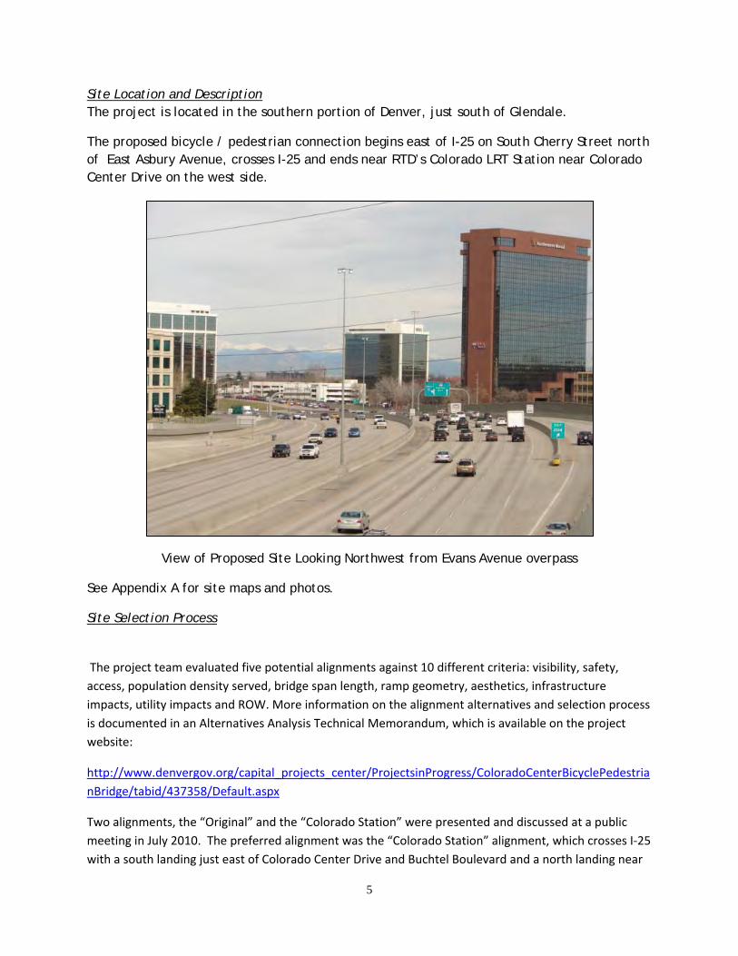
Site Location and Description The project is located in the southern portion of Denver, just south of Glendale.
The proposed bicycle / pedestrian connection begins east of I-25 on South Cherry Street north of East Asbury Avenue, crosses I-25 and ends near RTD’s Colorado LRT Station near Colorado Center Drive on the west side.
View of Proposed Site Looking Northwest from Evans Avenue overpass
See Appendix A for site maps and photos.
Site Selection Process
The project team evaluated five potential alignments against 10 different criteria: visibility, safety, access, population density served, bridge span length, ramp geometry, aesthetics, infrastructure impacts, utility impacts and ROW. More information on the alignment alternatives and selection process is documented in an Alternatives Analysis Technical Memorandum, which is available on the project website:
http://www.denvergov.org/capital_projects_center/ProjectsinProgress/ColoradoCenterBicyclePedestrianBridge/tabid/437358/Default.aspx
Two alignments, the “Original” and the “Colorado Station” were presented and discussed at a public meeting in July 2010. The preferred alignment was the “Colorado Station” alignment, which crosses I-25 with a south landing just east of Colorado Center Drive and Buchtel Boulevard and a north landing near
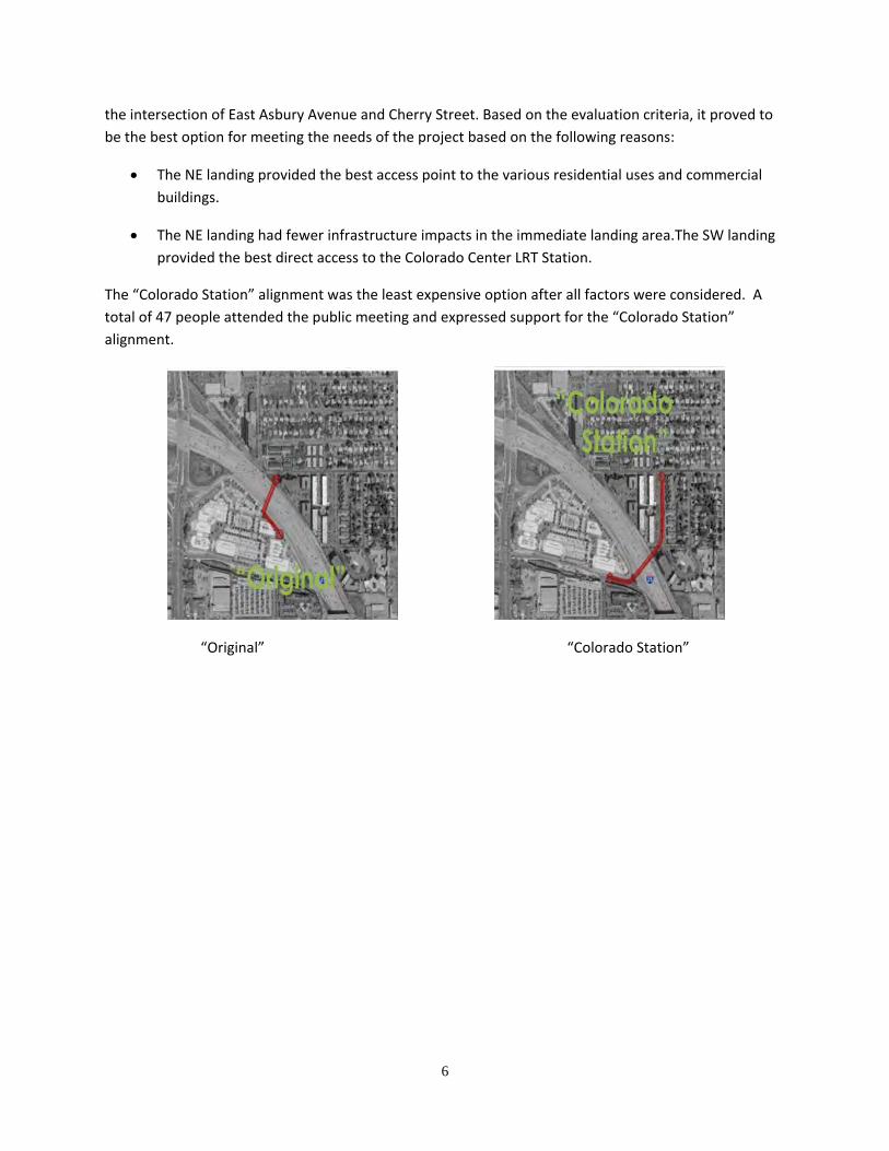
6
the intersection of East Asbury Avenue and Cherry Street. Based on the evaluation criteria, it proved to be the best option for meeting the needs of the project based on the following reasons:
• The NE landing provided the best access point to the various residential uses and commercial buildings.
• The NE landing had fewer infrastructure impacts in the immediate landing area.The SW landing provided the best direct access to the Colorado Center LRT Station.
The “Colorado Station” alignment was the least expensive option after all factors were considered. A total of 47 people attended the public meeting and expressed support for the “Colorado Station” alignment.
“Original” “Colorado Station”
7
PROJECT CRITERIA
Structural Design Criteria The structural design will be performed in accordance with current standard design codes governing the design of pedestrian bridges.
See Appendix B for a detailed description of the proposed design criteria.
Construction Phasing and Methods It is noted that construction will be in accordance with CDOT region 6 Lane closure policies, so I-25 traffic will be detoured around the project site during bridge erection. A detour on this major highway will negatively impact many people, so planning construction staging in order to minimize the duration of the detour is of paramount importance.
Dependent upon the structure type, several options to erect the structure could be utilized. Erection techniques are a critical piece in the selection of the recommended structure type.
The simplest erection technique is to construct the bridge on temporary falsework structures over the current I-25 alignment. This alternative is most likely not feasible since it would require an extended detour due to falsework structures in conflict with traffic lanes.
Another potential erection technique for constructing the bridge in-place would be to strategically place falsework supports along the alignment, possibly in the roadway medians and ramps. These strategically-placed falsework structures would be used to assemble the bridge in segments using short-duration highway closures. Once the bridge was stabilized and secured following each specific construction task, the highway would be re-opened. This technique would require long duration lane closures and a falsework protection system, but would reduce prolonged I-25 detours.
More complex erection techniques are possible that involve assembling the bridge off the alignment and then moving it into final position. These techniques are more expensive but would minimize the duration of the I-25 detour. Constructing the bridge in a temporary staging yard would require the contractor to secure a suitable space with adequate accessibility and a direct path to the final position. Finding a suitable staging yard may be difficult in this urban area.
Potential construction method alternatives that would minimize detour durations and will be considered during final design include, but are not limited to the following:
• The bridge could be erected in the space just southwest of the intersection of South Colorado Boulevard and I-25. The bridge would then be moved to the final position using self-propelled modular transporters (SPMT’s). SPMTs are platform vehicles with multiple wheels that are used to transport heavy objects over smooth surfaces. These are commonly used in the heavy civil industry but can be expensive and have limited availability in the United States. Following delivery to the final bridge site, the bridge

8
would be lifted into position using either the SPMT’s in conjunction with custom falsework or cranes.
• The bridge could be erected adjacent to the site between the existing infrastructure. Given the site conditions, this alternative may require closing parking lots, streets, etc. The bridge could then be maneuvered into position possibly using multiple cranes or custom-built rolling falsework.
• Segments of the structure could be erected at a nearby location. The segment lengths would be determined based on strategically place falsework supports along the alignment as previously mentioned. The segments would be transported to the site, set on the falsework and spliced together in a single overnight closure of I-25.
Right-of-Way Considerations Right-of-way acquisition is expected at each end of the bridge. The costs of this right-of-way are considered in the selection of the bridge alignment through evaluation of the amount of expected right-of-way and the ease of acquisition.
Hydraulics The bridge structure does not cross any waterways; therefore there are no hydraulics concerns with this structure.
Geology Data Geotechnical investigation has been completed and recommendations are for spread footings and drilled shafts. Final geotechnical recommendations are included in Shannon & Wilson, Inc’s report titled “GEOTECHNICAL REPORT, COLORADO CENTER BICYCLE/PEDESTRIAN BRIDGE”, August, 2011
Aesthetic Requirements The anticipated signature structure is intended to be aesthetically pleasing to pedestrians, bicyclists, local residents and businesses as well as to those travelling I-25.
With appropriate consideration given to meeting the budget, the bridge features (structural members, railing, details, etc.) and streetscaping / landscaping will be selected in order to maximize aesthetic appeal and to provide a positive experience for pedestrians and bicyclists. In addition, the project will complement the upscale urban setting.
Lighting Requirements The Colorado Center Bicycle/Pedestrian Bridge will be illuminated to provide visibility for user’s safe passage; Aesthetic highlighting of the bridge structure will also be considered and weighed against construction costs. Luminance levels will adhere to the Illuminating Engineering Society (IES) recommendations of 0.5 to 1.0 average footcandles with maximum to minimum uniformity below a 10:1 ratio. Colorado requires full cut-off luminaires which will be met with controlled glare luminaires. White-light sources will be used to provide high color rendition and visibility. Light pollution (wasted light into the sky) will be minimized by the use of the full cut-off luminaires which do not project light above the horizontal plane and light trespass (stray light onto adjacent areas) will be minimized with well controlled distribution of light and minimum yet sufficient light levels. Energy use will be the minimum

9
required to achieve the desired lighting levels and effects using high efficiency light sources and luminaires. The total energy use will be below the International Energy Conservation Code (IECC) allowances.
Bridge and ramp pathways will be lit with pedestrian scale decorative pole-mounted luminaires and supplemented with additional step, stair or other luminaires as required. The bridge structure may be subtly highlighted if the budget allows with minimal or no light trespass or pollution to the nearby residents or the roadway below. Controls will be considered to allow evening, night and late night adjustments to appropriate light levels. While further reducing energy use, the lighting may also be responsive to the traffic at a given time. Providing appropriate horizontal and vertical light levels on the pathways and controlled, target-specific structure illumination will achieve the goal of visually pleasing, comfortably safe and energy efficient lighting.

10
Utilities Major utilities near the project site that were considered during site selection and structure type have been identified and mapped. See Appendix C for graphics illustrating the utilities.
Environmental Considerations There are no significant environmental considerations that are unique to this project. This project is expected to be cleared though a Categorical Exclusion.
Traffic Control Bridge construction will affect the local traffic flows. These effects will be minimized through effective construction planning and phasing.
See “Construction Phasing and Methods” for further comments.
Public Information To keep the local public informed with the project, a series of public meetings and outreach events have occurred. The first public meeting was held on July 28, 2010 to introduce the project and identify the location alternatives. A local residents meeting was held on November 3, 2010 for the residents along Cherry St. A meeting was held on November 30, 2010 with a few residents of the Cherry Street Townehome who were unable to attend the previous meetings. Another public meeting is planned for fall of 2011 to update the public on design progress and anticipated construction activities.
See Appendix D for materials from the public meetings..

11
ALIGNMENT AND STRUCTURE TYPE ALTERNATIVES
Alignment Alternatives During the preliminary layout phase several landing sites were considered based on the site conditions and existing infrastructure. Based on the location of these potential landing sites, six alternatives were selected for further consideration. The alignment alternatives were evaluated for compliance with the overall project goals. A decision matrix was created to numerically evaluate each alternative, rank the alternatives and ultimately evaluate the options.
The decision matrix considered the following criteria in the evaluation:
• Visibility: Is the bridge visible from the light rail station and neighboring communities?
• Safety: Are the approach ramps in an active environment with perceived security?
• Access: Does the bridge provide a direct, short, and intuitive connection to major destinations?
• Bicycle / Pedestrian Usage: What is the density of potential users around the landing area?
• Bridge span length Longer spans are more costly.
• Ramp Geometry Does the ramp geometry (height, length, curve radius) provide easy pedestrian, bicyclist and maintenance vehicle access?
• Aesthetics Does the alignment allow for a bridge type with appropriate scale and fit with environmental context?
• Known Infrastructure Impacts Does the alignment interfere with parking lots, buildings, traffic, and highway signage?
• Utility Impacts How does the alignment fit with the existing utilities?
• Right-of-Way How much right-of-way does the alignment require and how difficult will it be to obtain the required right-of-way?
See Appendix E for details of the potential landing sites, alignment alternatives and the decision matrix.
Following the initial alignment study, the potential alignments were reduced to two alternatives for further study. The “Original” alignment and the “Colorado Station” alignments were submitted for review and comment by the City and County of Denver,

12
Colorado Department of Transportation and RTD. Evaluations by these agencies were performed considering landing geometry, potential grade transitions, accessibility, impacts to existing utilities, right-of-way acquisition, impacts to the local community, etc. As part of that evaluation reviewers were asked to comment on their preferred option. The “Colorado Station” option was the unanimous selection. See Appendix F for the recommended alignment alternative.
Structure Type Alternatives Alternatives presented in this section all pertain to the “Colorado Station” alignment.
Main Span
Several structure types are presented as potential selections to span I-25:
• Single-span “basket-handle” rib steel tied arch • Single-span square-rib steel tied arch • Prefabricated two-span through-truss • One-span through-trussTwo-span trapezoidal segmental post-tensioned box • Two-span trapezoidal composite steel boxTwo-span bulb tee prestressed concrete
girders (not pictured in appendices). • Prefabricated single span arch/through truss structure.
The two-span alternatives are deemed undesirable, as they would require an intermediate pier located at the median of I-25 and also lack the aesthetic qualities of a signature bridge.
The single-span arch bridge alternatives eliminate the intermediate pier while delivering the high profile aesthetic qualities of a signature structure. Three variations of the arch bridge concept are presented. The “basket handle” arch concept has canted arch ribs, whereas the squared arch concept has vertical arch ribs. The basket handle option provides a more unique and interesting look compared with the more traditional squared arch option. The third option is for a prefabricated single span arch/through truss structure. This option is a combination of the through truss and the squared arch concept. The introduction of the trough truss changes the appearance and is considered less aesthetically pleasing than the first two options, the prefabrication and design approach is more cost efficient while still providing a “signature” look.
The through-truss alternatives are low profile structure types that are stiff and possibly cost-effective, but lack the aesthetic qualities of a signature structure. The prefabricated two-span through-truss option (which requires an intermediate pier in the median of I-25) is included in the preliminary design and cost comparisons. The one-span through truss was not developed based on the anticipated structure weight and cost required to achieve the required span length.
The trapezoidal box alternatives are low profile and include classic aesthetics. These alternatives may be cost effective, but lack the high profile qualities of a signature structure. The trapezoidal box structure types were eliminated from further consideration because

13
these structure types would require raising the profile grade elevation to accommodate the entire superstructure under the bridge deck. (Discuss how raising grade affects ramp length)
The bulb tee prestressed concrete girder alternative is presented as a “utilitarian”, basic bridge option. This option is the lowest-cost alternative that would provide the required pedestrian / bicycle connectivity. The bulb tee prestressed concrete girders are utilized with a traditional composite cast-in-place concrete deck. This alternative requires an intermediate pier in the median of I-25 and is composed of four side-by-side BT72 girders. This option would require the profile to be raised by approximately 3 feet to meet the minimum vertical clearance of 17’-6”. Raising the profile would require an additional approach span on the west end to reduce wall heights. It would also reduce the at-grade landing length near the intersection of Colorado Center Drive and increase the length of the ramp along Cherry Street.
The “basket handle” tied arch concept, prefabricated two-span through-truss and the two-span prestressed girder concept were developed in preliminary design and carried through for cost comparisons.
See Appendix G for Main Span Structure Type Alternatives.
Approach Structures
Four elevated approach spans are required on the east side of I-25. Respective span lengths are 140 ft, 50 ft, 65 ft and 70 ft. The 140 ft span is required in order to meet ROW constraints. The 50 ft span is located over the entrance to the Cherry Plaza Apartment complex and meets the required 14’-6” vertical clearance to provide access for fire trucks.
Ramp approaches are required on the west side of I-25 and on the east side along Cherry Street to tie into the mainline bridge structure. Several structure type alternatives were evaluated for each elevated approach span and ramp structure as outlined below.
The 140 ft elevated approach span includes preliminary design and cost comparisons for BT63 bulb tee prestressed concrete girders and 60 inch deep side-by-side prestressed concrete box girders.
The 50 ft, 65 ft and 70 ft elevated approach spans include preliminary design and cost comparisons for 24 inch deep side-by-side prestressed concrete box girders and W24 steel rolled beams. Bulb tee prestressed concrete girders were not evaluated for these three spans due to structure depth limitations.
The ramp approach structures include preliminary design and cost comparisons for cast-in-place box structures and MSE walls with a moment slab to support the railing.
14
STRUCTURE TYPE ALTERNATIVES EVALUATION AND RECOMMENDATION
Selection Criteria The selection criteria for the structure types are correspondent with the overall project goals. Given the project objective to provide a signature pedestrian / bicycle bridge across I-25 within the established budget, the structure selection criteria vary by bridge component.
Selection criteria for the approach structures consist of cost and aesthetics considerations. While achieving a positive user experience and an aesthetic appeal, the approach structures are essentially recommended based on cost in order to preserve as much of the budget for the main span unit.
The structure type selection criteria for the main span consist of both cost and signature structure appeal. The largest portion of the budget is recommended to be allocated to the main span structure since it is the recognizable component of the bridge.
Estimate of Probable Construction Costs Estimates of probable construction costs have been studied and tabulated in Appendix H. For the main span, estimates of probable construction costs are provided for the basket handle arch concept, the prefabricated single span arch/through truss structure, the prefabricated two-span through-truss and the bulb tee prestressed girder alternatives. For the west and east approach ramps, estimates of probable construction costs are provided for the CIP box and MSE wall concepts. For the east approach structures, estimates of probable construction costs are provided for prestressed bulb tee, prestressed side by side box girders, and steel rolled beams.
Unit prices were used to evaluate the estimated construction costs. In general, the costs are based on:
• CDOT historical cost data from the previous three years (CDOT Cost Data Books) • Costs from local manufacturers for the prefabricated single span arch/through truss
structure • Costs from local manufacturers for the prefabricated two-span through-truss option • Previous similar pedestrian bridge projects, including:
o RTD’s McCaslin Pedestrian bridge over US 36 o RTD’s Pedestrian Bridge over US 36 at Broomfield Events Center o Highlands Pedestrian Bridge over I-25 near 16th St. o Pedestrian Bridges over I-235 (Des Moines, IA) o Bob Kerrey Pedestrian Bridge over Missouri River (Omaha, NE) o Wichita Riverfront Pedestrian Bridges (Wichita, KS) o Bagley Avenue Pedestrian Bridge over I-75 / I-96 (Detroit, MI)
• Price quotations from specific product manufacturers based on preliminary design information

15
The costs of right-of-way acquisition are not included in the cost estimates presented here. All the options presented utilize the same right-of-way, so the structure type selection is independent of right-of-way acquisition costs.
See Appendix H for the Estimate of Probable Construction Costs.
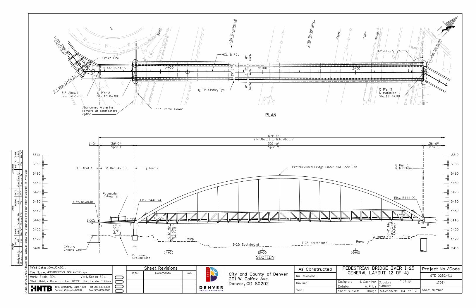
Structure Recommendation Main Span
The recommended structure type for the main span is the prefabricated single span arch/through truss. It is the most signature option that fits within the proposed construction budget. This bridge type delivers the high profile look and aesthetic appeal that is desired for this project while providing the critical connectivity across I-25 for local pedestrians and bicyclists. This structure type will fit well into the urban setting and will be an icon for this area.
Ramp Approach Structures
The recommended structure type for the approach ramp structures for both the east and west sides of the project is MSE walls. This alternative was the most economical option. This structure type fits well with the overall bridge aesthetic and elegantly achieves the grade change objectives to meet the vertical alignment of the main span.
Elevated Approach Spans
The recommended structure type for the elevated approach spans at the east side of the main span is side-by-side prestressed concrete box girders. 60 inch deep box girders are required for the 140 ft span and 24 inch deep box girders are required for the remaining 3 approach spans. Prestressed box girders are the most economical alternative for the 50 ft, 65 ft and 70 ft approach spans.
Prestressed box girders were also selected for the 140 ft span to maintain aesthetics on these four spans. The BT63 alternative is slightly more economical yet requires a deeper structure depth and does not maintain the aesthetic pattern of the box girders. Thus box girders were also selected for this span.
Summary
The recommended structure types for each component of the bridge will collectively achieve the project objectives. The total anticipated construction costs for the recommended alternatives are within the total project budget, and construction can be completed according to the desired schedule.
See Appendix I for the proposed site plan and structure type alternative details.

APPENDIX A: SITE MAPS AND PHOTOS
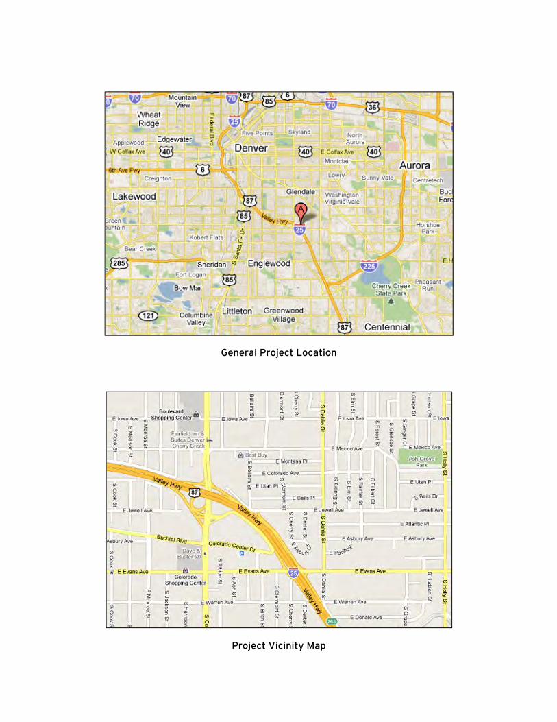
General Project Location
Project Vicinity Map

View Looking Southwest from North side of I-25
View Looking North from Colorado Center
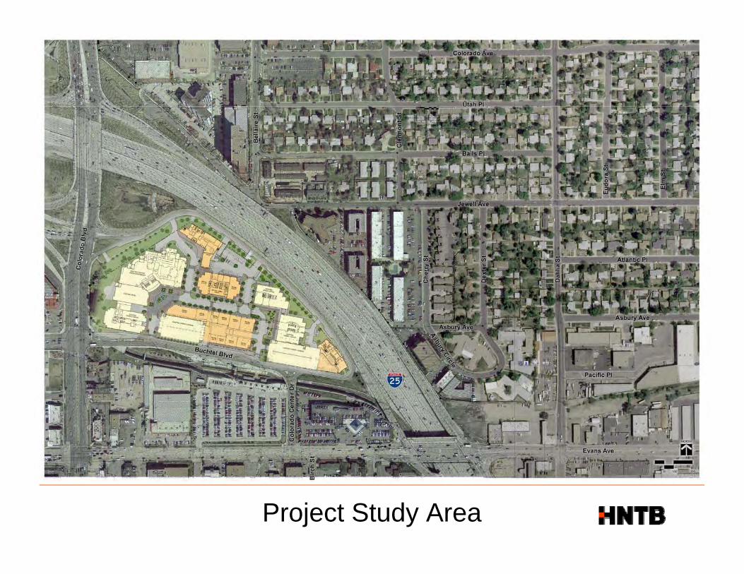
Project Study Area
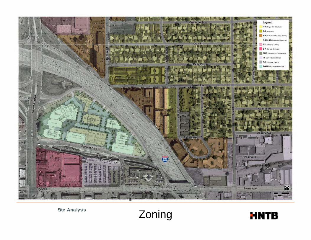
Site AnalysisZoning
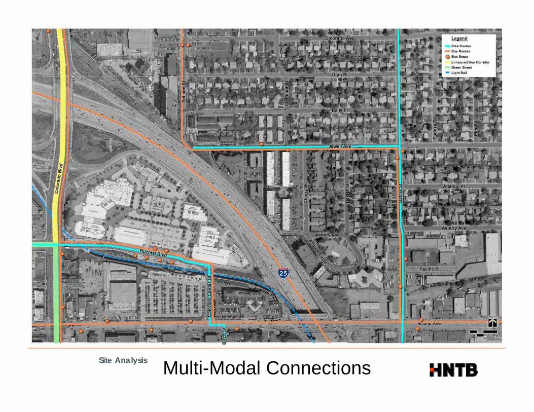
Site AnalysisMulti-Modal Connections

APPENDIX B: STRUCTURE DESIGN CRITERIA
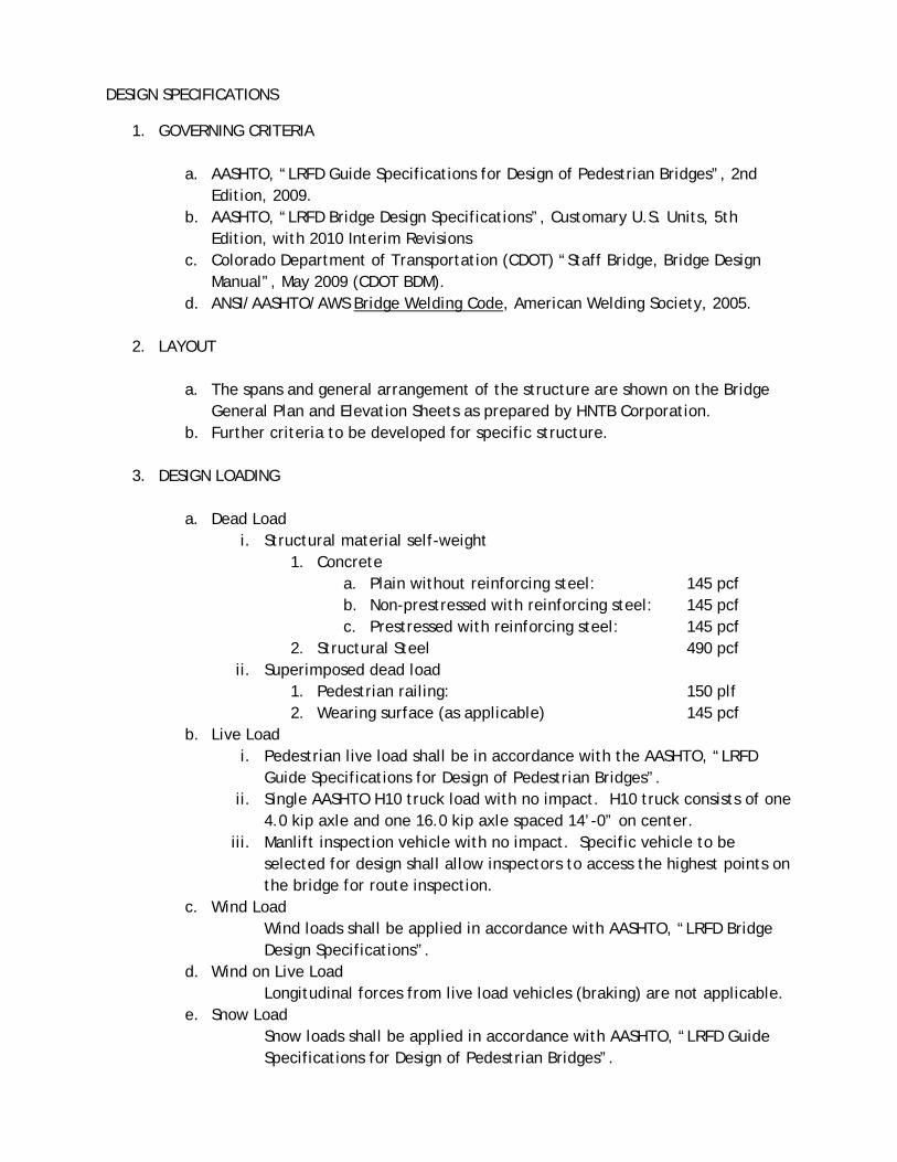
DESIGN SPECIFICATIONS
1. GOVERNING CRITERIA
a. AASHTO, “LRFD Guide Specifications for Design of Pedestrian Bridges”, 2nd Edition, 2009.
b. AASHTO, “LRFD Bridge Design Specifications”, Customary U.S. Units, 5th Edition, with 2010 Interim Revisions
c. Colorado Department of Transportation (CDOT) “Staff Bridge, Bridge Design Manual”, May 2009 (CDOT BDM).
d. ANSI/AASHTO/AWS Bridge Welding Code, American Welding Society, 2005.
2. LAYOUT
a. The spans and general arrangement of the structure are shown on the Bridge General Plan and Elevation Sheets as prepared by HNTB Corporation.
b. Further criteria to be developed for specific structure.
3. DESIGN LOADING
a. Dead Load i. Structural material self-weight
1. Concrete a. Plain without reinforcing steel: 145 pcf b. Non-prestressed with reinforcing steel: 145 pcf c. Prestressed with reinforcing steel: 145 pcf
2. Structural Steel 490 pcf ii. Superimposed dead load
1. Pedestrian railing: 150 plf 2. Wearing surface (as applicable) 145 pcf
b. Live Load i. Pedestrian live load shall be in accordance with the AASHTO, “LRFD
Guide Specifications for Design of Pedestrian Bridges”. ii. Single AASHTO H10 truck load with no impact. H10 truck consists of one
4.0 kip axle and one 16.0 kip axle spaced 14’-0” on center. iii. Manlift inspection vehicle with no impact. Specific vehicle to be
selected for design shall allow inspectors to access the highest points on the bridge for route inspection.
c. Wind Load Wind loads shall be applied in accordance with AASHTO, “LRFD Bridge Design Specifications”.
d. Wind on Live Load Longitudinal forces from live load vehicles (braking) are not applicable.
e. Snow Load Snow loads shall be applied in accordance with AASHTO, “LRFD Guide Specifications for Design of Pedestrian Bridges”.

f. Thermal Load Thermal loads shall be applied in accordance with AASHTO, “LRFD Bridge Design Specifications”.
g. Seismic Load Seismic loads shall be applied in accordance with AASHTO, “LRFD Bridge Design Specifications”.
h. Longitudinal Forces Longitudinal forces from live load vehicles (braking) are not applicable.
i. Pedestrian Induced Vibrations Structural effects caused by pedestrian induced vibrations shall be considered in accordance with AASHTO, “LRFD Guide Specifications for Design of Pedestrian Bridges”.
j. Extreme Event Loading Piers positioned such that vehicle collision is possible shall be designed for vehicle collision load in accordance with AASHTO, “LRFD Bridge Design Specifications”.
4. LOAD COMBINATIONS
The bridge shall be designed for the load combinations and load factors specified in AASHTO LRFD Table 3.4.1-1 with the following exceptions:
Load combinations Strength II, Strength IV, and Strength V shall not be considered. The load factor for the Fatigue I load combination shall be taken as 1.0, and the
Fatigue II load combination need not be considered.
5. MATERIALS Material specifications to be determined based on selected structure type.
6. GEOMETRY CONSTRAINTS AND MINIMUM CLEARANCES
a. The bridge shall be accessible for pedestrians and bicyclists and shall be ADA compliant.
b. Bridge width shall be designed to a minimum width of 10 ft clear (14 ft clear is preferred).
c. Minimum vertical clearance for pedestrian / bicycle traffic (carried on the bridge) is 10 ft.
d. Minimum vertical clearance over I-25 is 17 ft 6 inches. e. Minimum vertical clearance over all city streets is 14 ft 6 inches. (Reference
2005 CDOT Roadway Design Manual.)
NOTE: Design criteria shall be updated and refined based on structure type selected for final design.

APPENDIX C: UTILITIES

Site AnalysisUtilities

Site AnalysisUtilities


APPENDIX D: PUBLIC MEETING MATERIALS
(JULY 28, 2010)
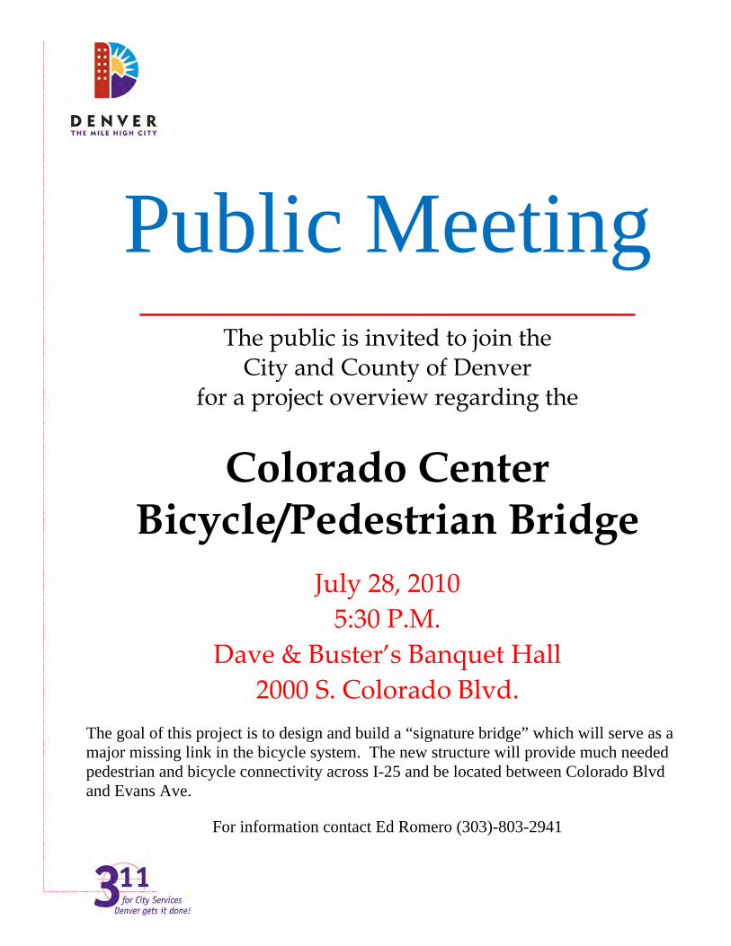
Public Meeting _______________________
The public is invited to join the City and County of Denver
for a project overview regarding the
Colorado Center Bicycle/Pedestrian Bridge
July 28, 2010
5:30 P.M.
Dave & Buster’s Banquet Hall
2000 S. Colorado Blvd.
The goal of this project is to design and build a “signature bridge” which will serve as a major missing link in the bicycle system. The new structure will provide much needed pedestrian and bicycle connectivity across I-25 and be located between Colorado Blvd and Evans Ave.
For information contact Ed Romero (303)-803-2941

Agenda Public Information Meeting
Bicycle/Pedestrian Bridge over I-25 @ Colorado Blvd.
I. Welcome - Ed Romero, Consultant Public Information Manager (2 Min)
Welcome and introduction of Councilman Brown.
II. Councilman Brown
III. Project Overview - Jim Hamblin, CCD Project Manager (2 Min)
History of the project and funding Bridge Location Study by Felsburg Holt & Ullevig Selection of HNTB as design consultant. Introduction of John Guenther
IV. Site Selection Process - John Guenther, Design Consultant Project Manager (2 Min)
HNTB Site review / Selection Process Overview Introduction of Kelly VanElders
V. Site Selection - Kelly VanElders, Design Consultant Urban Planner (15 Min)
Review of Potential Sites Site Selection Process Conclusion of Site Selection Process
VI. Next Steps - John Guenther, Design Consultant Project Manager (5 Min)
Potential Bridge Types Project Schedule Future Public Information Meeting
VII. Questions - John Guenther, Design Consultant Project Manager
VIII. More Information - For more information on the project contact:
James Hamblin, P.E. John Guenther, P.E. CCD Project Manager HNTB Project Manager (720) 865-3167 (303) 542-2214 [email protected] [email protected]


APPENDIX E: ALIGNMENT ALTERNATIVES

Site AnalysisPotential Landing Sites

Site AnalysisInitial Landing Sites Studied

Conceptual Alignment Diagrams

COLORADO CENTER LOCATION MATRIX
CRITERIA WEIGHT LOCATIONTOTAL SCORE LOCATION
TOTAL SCORE LOCATION
TOTAL SCORE LOCATION
TOTAL SCORE LOCATION
TOTAL SCORE COMMENTS
Weight = 1 to 5
Ranking 1 to 10
Weight x Ranking
Ranking 1 to 10
Weight x Ranking
Ranking 1 to 10
Weight x Ranking
Ranking 1 to 10
Weight x Ranking
Ranking 1 to 10
Weight x Ranking
JEWELL COLORADO
HNTB Evaluation
GATEWAY ORIGINALJEWELL CARE TOD
COLORADOSTATION
VISIBILITY - Visual relationship between bridge and light rail station
Good visibility = 10 Bad visibility = 0
North 3 7 21 9 27 6 18 2 6 8 24
South 3 0 0 2 6 1 3 1 3 10 30No visibility corridor - blocked by Colorado Center Development
SAFETY - Ramp in an active environment with perceived security
Safe = 10Unsafe = 0
North 5 10 50 6 30 6 30 4 20 7 35North 5 10 50 6 30 6 30 4 20 7 35South 5 10 50 7 35 7 35 7 35 9 45
ACCESS - Direct, short, and intuitive connection to major destinations
Good access = 10Bad access = 0
North 5 1 5 9 45 9 45 9 45 9 45South 5 3 15 8 40 5 25 5 25 10 50
BIKES/(PEDS) USAGE - Density and potential users within landing area
Good usage = 10Bad usage = 0
North 4 1 4 8 32 8 32 8 32 8 32South 4 1 4 4 16 3 12 3 12 9 36South 4 1 4 4 16 3 12 3 12 9 36
BRIDGE SPAN LENGTHShorter bridge length = 10longer = 0
4 3 12 9 36 8 32 5 20 8 32
RAMP GEOMETRY - Height, length, radius of turn, maintenance vehicle access
Good ramp geometry = 10Bad ramp geometry = 0
North 4 9 36 3 12 3 12 4 16 9 36South 4 9 36 6 24 3 12 5 20 10 40
AESTHETICS - Mass, fit into built en ironment and conte t
Good aesthetics = 10Bad aesthetics 0environment and context Bad aesthetics = 0
North 2 9 18 3 6 3 6 7 14 6 12South 2 8 16 6 12 5 10 6 12 9 18
KNOWN INFRASTRUCTURE IMPACTS -Parking, buildings, traffic, highway signage
No infrastructure impacts = 10High infrastructure impacts = 0
North 3 10 30 2 6 2 6 1 3 4 12South 3 10 30 7 21 7 21 7 21 10 30
UTILITY IMPACTS - Surface and subsurface public & private facilities
No utility impacts = 10High utility impacts = 0p p g y p
North 4 7 28 5 20 5 20 8 32 6 24South 4 7 28 8 32 8 32 8 32 8 32
ROW - Amount and ease of acquisition No ROW impacts = 10High ROW impact = 0
North 5 8 40 2 10 2 10 0 0 2 10South 5 8 40 6 30 6 30 6 30 9 45
TOTALS 463 440 391 378 588
Decision Matrix
GATEWAY ORIGINAL JEWELL CARE TOD COLORADO STATION
“O i i l”“Original”
“ColoradoColoradoStation”
Selected Conceptual Diagrams
Frontage Interstate 25 JewellFrontage Road
Interstate 25 JewellAve
Site Analysis Original Site Grade TransitionsAccess and Utility Issues

Conceptual Diagram“Original”

Conceptual Design“Original”

North Landing“Original”

South Landing“Original”

Conceptual Diagram“Colorado Station”

Conceptual Design“Colorado Station”
North Landing“Colorado Station”
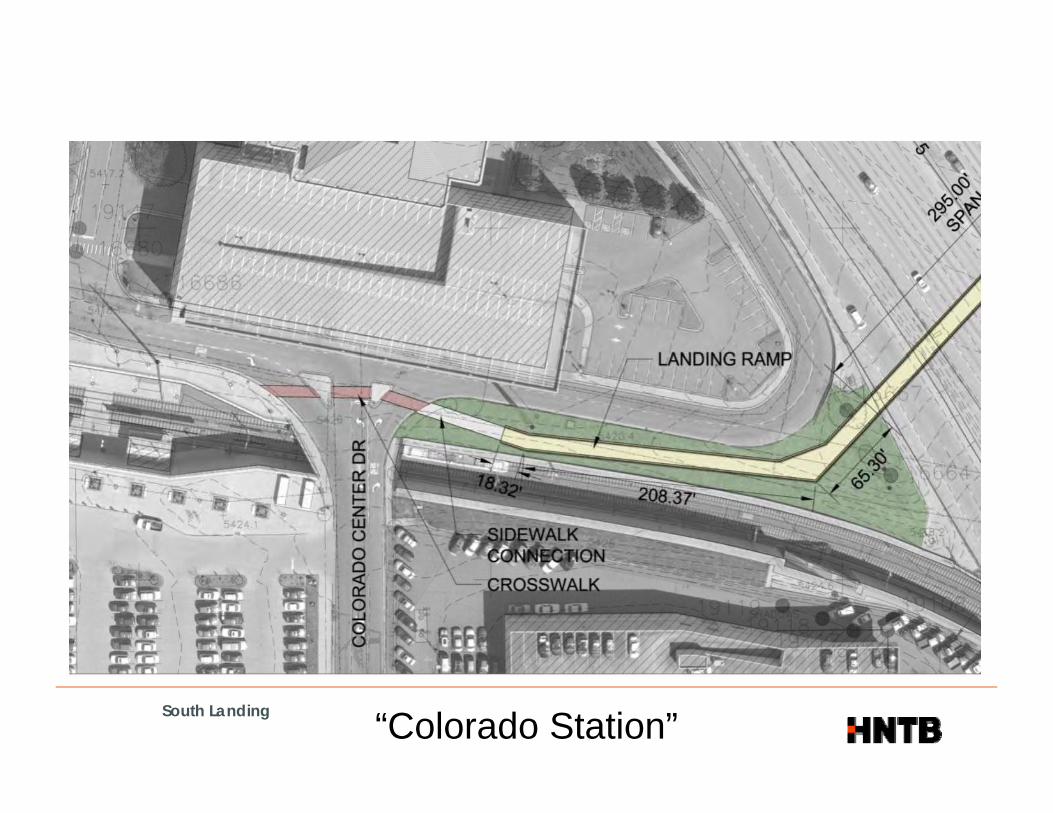
South Landing“Colorado Station”

APPENDIX F: RECOMMENDED ALIGNMENT


APPENDIX G: MAIN SPAN STRUCTURE TYPE ALTERNATIVES
(FOR RECOMMENDED ALIGNMENT)
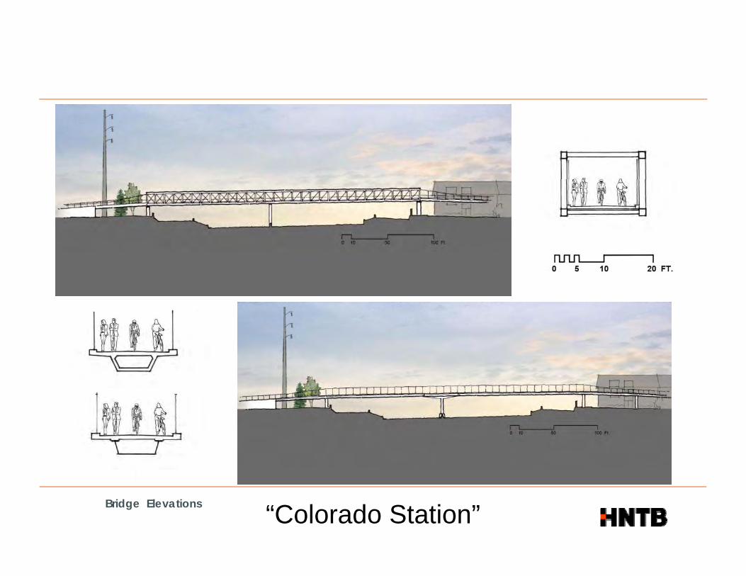
Bridge Elevations“Colorado Station”

Bridge Elevations“Colorado Station”

Bridge Perspective“Colorado Station”
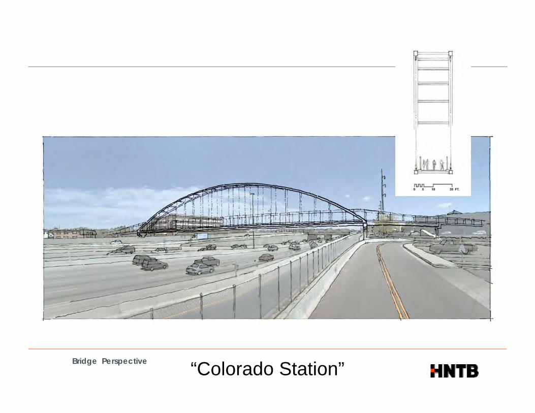
Bridge Perspective“Colorado Station”
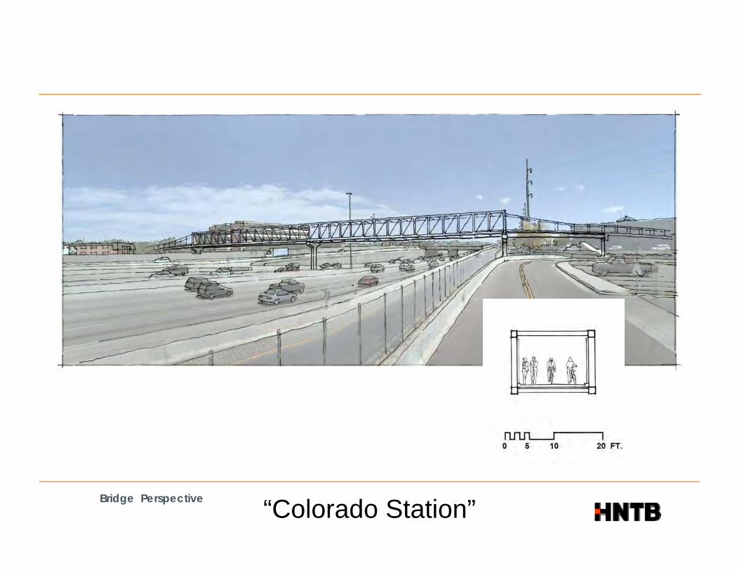
Bridge Perspective“Colorado Station”

Bridge Perspective“Colorado Station”

APPENDIX H: ESTIMATE OF PROBABLE CONSTRUCTION COSTS

Made JVM Date 12/15/2010 Job Number 49589
Checked ALS Date 12/15/2010
For Colorado Center Bicycle/ Pedestrian Bridge Backchk'd Date Sheet No.
ALTERNATIVE A: SINGLE SPAN BASKET-HANDLE TIED ARCH OVER I-25
West Ramp: MSE $388,133 $58,220 $19,407 $465,760 3600 $129Main Single Span: Basket-Handle Tied Arch $3,658,869 $548,830 $182,943 $4,390,643 4907 $895140' Approach: BX60 $253,546 $38,032 $12,677 $304,255 2065 $14750' Approach: BX24 $93,097 $13,965 $4,655 $111,716 738 $15165' Approach: BX24 $104,513 $15,677 $5,226 $125,416 813 $15470' Approach: BX24 $94,462 $14,169 $4,723 $113,354 875 $130Cherry Street Ramp: MSE $178,065 $26,710 $8,903 $213,678 2019 $106
Grand Total =
ALTERNATIVE B: TWO SPAN PREFABRICATED THROUGH-TRUSS OVER I-25
West Ramp: MSE $388,133 $58,220 $19,407 $465,760 3600 $129Main 2 Span: Through-Truss $1,203,502 $180,525 $60,175 $1,444,202 4720 $306140' Approach: BX60 $253,546 $38,032 $12,677 $304,255 2065 $14750' Approach: BX24 $93,097 $13,965 $4,655 $111,716 738 $15165' Approach: BX24 $104,513 $15,677 $5,226 $125,416 813 $15470' Approach: BX24 $94,462 $14,169 $4,723 $113,354 875 $130Cherry Street Ramp: MSE $178,065 $26,710 $8,903 $213,678 2019 $106
Grand Total =
ALTERNATIVE C: TWO SPAN PREFABRICATED THROUGH-TRUSS OVER I-25
Total / SF
Total / SF
$5,724,822
Subtotal15%
Contingency5%
MobilizationTotal Area
$2,778,382
Subtotal15%
Contingency5%
MobilizationTotal Area
The HNTB CompaniesEngineers Architects Planners
ALTERNATIVE C: TWO SPAN PREFABRICATED THROUGH TRUSS OVER I 25
West Ramp: MSE $388,133 $58,220 $19,407 $465,760 3600 $129Main 1 Span: Through-Truss / Arch $1,312,420 $196,863 $65,621 $1,574,904 4720 $334140' Approach: BX60 $253,546 $38,032 $12,677 $304,255 2065 $14750' Approach: BX24 $93,097 $13,965 $4,655 $111,716 738 $15165' Approach: BX24 $104,513 $15,677 $5,226 $125,416 813 $15470' Approach: BX24 $94,462 $14,169 $4,723 $113,354 875 $130Cherry Street Ramp: MSE $178,065 $26,710 $8,903 $213,678 2019 $106
Grand Total =
J:\49589 CCD Colorado Center Ped Bridge\TECHPROD\BRDG\PreliminaryDesign\Excel\[CCD_Ped_Cost Comparison_ElevatedSections.xls]Totals both
$2,909,083
Subtotal15%
Contingency5%
MobilizationTotal Area Total / SF
The HNTB CompaniesEngineers Architects Planners
Made JVM Date 12/10/2010 Job Number 49589
Checked ALS Date 12/13/2010
For CCD Ped Bridge Backchk'd Date Sheet No.
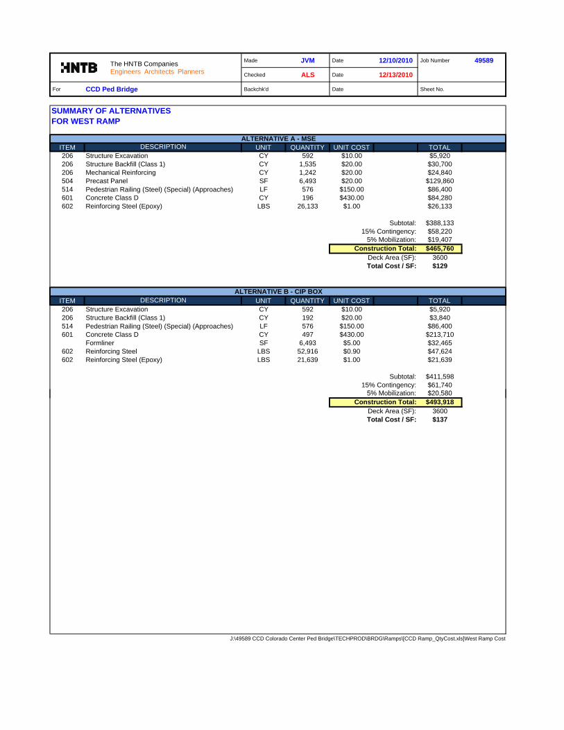
SUMMARY OF ALTERNATIVESFOR WEST RAMP
ITEM DESCRIPTION UNIT QUANTITY UNIT COST TOTAL206 Structure Excavation CY 592 $10.00 $5,920206 Structure Backfill (Class 1) CY 1,535 $20.00 $30,700206 Mechanical Reinforcing CY 1,242 $20.00 $24,840504 Precast Panel SF 6,493 $20.00 $129,860514 Pedestrian Railing (Steel) (Special) (Approaches) LF 576 $150.00 $86,400601 Concrete Class D CY 196 $430.00 $84,280602 Reinforcing Steel (Epoxy) LBS 26,133 $1.00 $26,133
$388,133$58,220$19,407
$465,760Deck Area (SF): 3600Total Cost / SF: $129
ITEM DESCRIPTION UNIT QUANTITY UNIT COST TOTAL206 Structure Excavation CY 592 $10.00 $5,920206 Structure Backfill (Class 1) CY 192 $20.00 $3,840514 Pedestrian Railing (Steel) (Special) (Approaches) LF 576 $150.00 $86,400601 Concrete Class D CY 497 $430.00 $213,710
Formliner SF 6,493 $5.00 $32,465602 Reinforcing Steel LBS 52,916 $0.90 $47,624602 Reinforcing Steel (Epoxy) LBS 21,639 $1.00 $21,639
$411,598$61,740$20 580
ALTERNATIVE B - CIP BOX
Subtotal:15% Contingency:
5% M bili ti
ALTERNATIVE A - MSE
Construction Total:5% Mobilization:
15% Contingency:Subtotal:
The HNTB CompaniesEngineers Architects Planners
$20,580$493,918
Deck Area (SF): 3600Total Cost / SF: $137
J:\49589 CCD Colorado Center Ped Bridge\TECHPROD\BRDG\Ramps\[CCD Ramp_QtyCost.xls]West Ramp Cost
5% Mobilization:Construction Total:

Made JPBo Date 12/10/2010 Job Number 49589
Checked FPB Date 12/15/2010
For Colorado Center Bicycle/ Pedestrian Bridge Backchk'd Date Sheet No.
MAIN SPAN: ALTERNATIVE ABasket-Handle Tied Arch (Welded Box Arch Rib with Typical Hanger Cables)
ITEM DESCRIPTION UNIT QUANTITY UNIT COST TOTAL
SUPERSTRUCTURE
509 Structural Steel lbs 759818 $3.75 $2,849,318514 Pedestrian Railing (Steel) (Special) (Mainspan) lf 640 $250.00 $160,000518 Bridge Expansion Device (0-4in) lf 25 $175.00 $4,375520 Bridge Hanger Cable Assembly ls 1 $155,000.00 $155,000601 Concrete (Class D) (Bridge) cy 164 $430.00 $70,520602 Reinforcing Steel (Epoxy) lb 24,600 $1.00 $24,600613 Electric Lighting System ls 1 $125,000.00 $125,000
Subtotal: $3,388,813
SUBSTRUCTURE
206 Structure Excavation cy 120 $10.00 $1,200503 Drilled Caissons (48 Inch) lf 300 $350.00 $105,000512 Bearing Device (Type III) ea 4 $7,500.00 $30,000601 Concrete (Class D) (Bridge) cy 232 $430.00 $99,760601 Structural Concrete Stain sy 193 $10.00 $1,930602 Reinforcing Steel lb 26,081 $0.90 $23,473602 Reinforcing Steel (Epoxy) lb 8,694 $1.00 $8,694
ALTERNATIVE A - BASKET-HANDLE TIED ARCH
The HNTB CompaniesEngineers Architects Planners
Subtotal: $270,057
$3,658,869$548,830$182,943
$4,390,643Deck Area (SF) = 4907Total Cost / SF = $894.83
J:\49589 CCD Colorado Center Ped Bridge\TECHPROD\BRDG\Excel\[Mainspan_Cost_for_Joseffa_121710.xlsx]Mainspan_Cost_Summ
Subtotal:15% Contingency:
5% Mobilization:Construction Total:
The HNTB CompaniesEngineers Architects Planners

Made ALS Date 12/9/2010 Job Number 49589
Checked JVM Date 12/13/2010
For Colorado Center Bicycle/ Pedestrian Bridge Backchk'd Date Sheet No.
SUMMARY OF ALTERNATIVESFor Main Two-Span (170'-0" & 150'-0")
ITEM DESCRIPTION UNIT QUANTITY UNIT COST TOTAL206 Structure Excavation 3685029 245 $10.00 $2,450206 Structure Backfill (Class 1) cy 208 $20.00 $4,160503 Drilled Caissons (48 Inch) lf 89 $350.00 $31,150503 Drilled Caissons (54 Inch) lf 138 $400.00 $55,200504 Precast Panel Facing sf 208 $20.00 $4,160512 Bearing Device (Type 1) ea 8 $750.00 $6,000514 Pedestrian Railing (Steel) (Special) (Mainspan Truss) lf 640 $100.00 $64,000518 Bridge Expansion Device (0-4in) lf 25 $175.00 $4,375601 Concrete (Class D) (Bridge) cy 118 $430.00 $50,740601 Structural Concrete Stain sy 131 $10.00 $1,310602 Reinforcing Steel lbs 13,312 $0.90 $11,981602 Reinforcing Steel (Epoxy) lbs 4,438 $1.00 $4,438613 Electrical Lighting System ls 1 $125,000.00 $125,000628 Bridge Girder and Deck Unit (170' Span) ea 1 $451,350.00 $451,350628 Bridge Girder and Deck Unit (150' Span) ea 1 $387,188.00 $387,188
Subtotal: $1,203,50215% Contingency: $180,525
5% Mobilization: $60,175$1,444,202
Deck Area (SF) = 4720Total Cost / SF = $305.98
ITEM DESCRIPTION UNIT QUANTITY UNIT COST TOTAL206 Structure Excavation cy 245 $10.00 $2,450206 Structure Backfill (Class 1) cy 208 $20.00 $4,160
ALTERNATIVE C - BT72 (SIDE-BY-SIDE)
Construction Total:
ALTERNATIVE B - PREFABRICATED TWO-SPAN THROUGH-TRUSS
The HNTB CompaniesEngineers Architects Planners
206 Structure Backfill (Class 1) cy 208 $20.00 $4,160503 Drilled Caissons (48 Inch) lf 89 $350.00 $31,150503 Drilled Caissons (54 Inch) lf 138 $400.00 $55,200504 Precast Panel Facing sf 208 $20.00 $4,160512 Bearing Device (Type 1) ea 8 $750.00 $6,000514 Pedestrian Railing (Steel) (Special) (Mainspan) lf 640 $250.00 $160,000518 Bridge Expansion Device (0-4in) lf 25 $175.00 $4,375601 Concrete (Class D) (Bridge) cy 263 $430.00 $113,090601 Structural Concrete Stain sy 869 $10.00 $8,690602 Reinforcing Steel lb 13,312 $0.90 $11,981602 Reinforcing Steel (Epoxy) lb 19,793 $1.00 $19,793613 Electrical Lighting System ls 1 $125,000.00 $125,000618 Prestressed Concrete I (BT72) lf 1,280 $190.00 $243,200
Subtotal: $789,24915% Contingency: $118,387
5% Mobilization: $39,462$947,099
Deck Area (SF) = 4720Total Cost / SF = $200.66 *
J:\49589 CCD Colorado Center Ped Bridge\TECHPROD\BRDG\Excel\[CCD_Ped_Cost Comparison_ElevatedSections.xls]Main Truss BT
Construction Total:
* Note, the BT72 option requires the profile to be raised to meet required vertical clearance. This would require additional approach spans and longer ramps. These implications were not taken into account for this cost comparison.
The HNTB CompaniesEngineers Architects Planners

Made ALS Date 12/9/2010 Job Number 49589
Checked JVM Date 12/13/2010
For Colorado Center Bicycle/ Pedestrian Bridge Backchk'd Date Sheet No.
SUMMARY OF ALTERNATIVESFor 140'-0" Span
ITEM DESCRIPTION UNIT QUANTITY UNIT COST TOTAL206 Structure Excavation 3685029 129 $10.00 $1,290206 Structure Backfill (Class 1) cy 109 $20.00 $2,180503 Drilled Caissons (48 Inch) lf 71 $350.00 $24,850514 Pedestrian Railing (Steel) (Special) (Approaches) lf 280 $150.00 $42,000601 Concrete (Class D) (Bridge) cy 126 $430.00 $54,180601 Structural Concrete Stain sy 401 $10.00 $4,010602 Reinforcing Steel lb 7,220 $0.90 $6,498602 Reinforcing Steel (Epoxy) lb 9,338 $1.00 $9,338618 Prestressed Concrete Box (Depth Greater Than 48") lf 1,680 $65.00 $109,200
$253,546$38,032$12,677$304,255
Deck Area (SF) = 2065Total Cost / SF = $147.34
ITEM DESCRIPTION UNIT QUANTITY UNIT COST TOTAL206 Structure Excavation cy 129 $10.00 $1,290206 Structure Backfill (Class 1) cy 109 $20.00 $2,180503 Drilled Caissons (48 Inch) lf 71 $350.00 $24,850514 Pedestrian Railing (Steel) (Special) (Approaches) lf 280 $150.00 $42,000601 Concrete (Class D) (Bridge) cy 145 $430.00 $62,350601 Structural Concrete Stain sy 429 $10.00 $4,290
ALTERNATIVE A - 60 INCH DEEP SIDE-BY-SIDE BOXES
Subtotal:15% Contingency:
5% Mobilization:Construction Total:
ALTERNATIVE B - BT63
The HNTB CompaniesEngineers Architects Planners
601 Structural Concrete Stain sy 429 $10.00 $4,290602 Reinforcing Steel lb 7,220 $0.90 $6,498602 Reinforcing Steel (Epoxy) lb 12,330 $1.00 $12,330618 Prestressed Concrete I (BT63) lf 420 $180.00 $75,600
$231,388$34,708$11,569$277,666
Deck Area (SF) = 2065Total Cost / SF = $134.46
J:\49589 CCD Colorado Center Ped Bridge\TECHPROD\BRDG\Excel\[CCD_Ped_Cost Comparison_ElevatedSections.xls]Summary 140
Subtotal:15% Contingency:
5% Mobilization:Construction Total:

Made ALS Date 12/6/2010 Job Number 49589
Checked JVM Date 12/13/2010
For Colorado Center Bicycle/ Pedestrian Bridge Backchk'd Date Sheet No.
SUMMARY OF ALTERNATIVESFor 50'-0" Span
ITEM DESCRIPTION UNIT QUANTITY UNIT COST TOTAL206 Structure Excavation 3685029 89 $10.00 $890206 Structure Backfill (Class 1) cy 76 $20.00 $1,520503 Drilled Caissons (42 Inch) lf 60 $300.00 $18,000514 Pedestrian Railing (Steel) (Special) (Approaches) lf 100 $150.00 $15,000601 Concrete (Class D) (Bridge) cy 53 $430.00 $22,790601 Structural Concrete Stain sy 124 $10.00 $1,240602 Reinforcing Steel lb 3,320 $0.90 $2,988602 Reinforcing Steel (Epoxy) lb 3,669 $1.00 $3,669618 Prestressed Concrete Box (Depth Less Than 32") sf 600 $45.00 $27,000
$93,097$13,965$4,655
$111,716Deck Area (SF) = 738Total Cost / SF = $151.48
ITEM DESCRIPTION UNIT QUANTITY UNIT COST TOTAL206 Structure Excavation cy 89 $10.00 $890206 Structure Backfill (Class 1) cy 76 $20.00 $1,520503 Drilled Caissons (42 Inch) lf 60 $300.00 $18,000509 Structural Steel lb 14,490 $3.75 $54,338512 Bearing Device (Type 1) ea 6 $750.00 $4,500
ALTERNATIVE A - 24 INCH DEEP SIDE-BY-SIDE BOXES
Subtotal:15% Contingency:
5% Mobilization:Construction Total:
ALTERNATIVE B - ROLLED STEEL BEAMS
The HNTB CompaniesEngineers Architects Planners
512 Bearing Device (Type 1) ea 6 $750.00 $4,500514 Pedestrian Railing (Steel) (Special) (Approaches) lf 100 $150.00 $15,000601 Concrete (Class D) (Bridge) cy 56 $430.00 $24,080601 Structural Concrete Stain sy 137 $10.00 $1,370602 Reinforcing Steel lb 3,320 $0.90 $2,988602 Reinforcing Steel (Epoxy) lb 4,789 $1.00 $4,789
$127,475$19,121$6,374
$152,969Deck Area (SF) = 738Total Cost / SF = $207.42
J:\49589 CCD Colorado Center Ped Bridge\TECHPROD\BRDG\Excel\[CCD_Ped_Cost Comparison_ElevatedSections.xls]Summary 50
Subtotal:15% Contingency:
5% Mobilization:Construction Total:
Made ALS Date 12/7/2010 Job Number 49589
Checked JVM Date 12/13/2010
For Colorado Center Bicycle/ Pedestrian Bridge Backchk'd Date Sheet No.
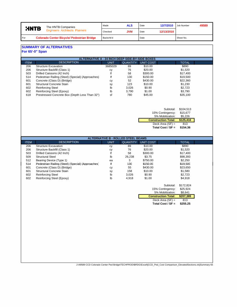
SUMMARY OF ALTERNATIVESFor 65'-0" Span
ITEM DESCRIPTION UNIT QUANTITY UNIT COST TOTAL206 Structure Excavation 3685029 89 $10.00 $890206 Structure Backfill (Class 1) cy 76 $20.00 $1,520503 Drilled Caissons (42 Inch) lf 58 $300.00 $17,400514 Pedestrian Railing (Steel) (Special) (Approaches) lf 130 $150.00 $19,500601 Concrete (Class D) (Bridge) cy 52 $430.00 $22,360601 Structural Concrete Stain sy 123 $10.00 $1,230602 Reinforcing Steel lb 3,026 $0.90 $2,723602 Reinforcing Steel (Epoxy) lb 3,790 $1.00 $3,790618 Prestressed Concrete Box (Depth Less Than 32") sf 780 $45.00 $35,100
$104,513$15,677$5,226
$125,416Deck Area (SF) = 813Total Cost / SF = $154.36
ITEM DESCRIPTION UNIT QUANTITY UNIT COST TOTAL206 Structure Excavation cy 89 $10.00 $890206 Structure Backfill (Class 1) cy 76 $20.00 $1,520503 Drilled Caissons (42 Inch) lf 58 $300.00 $17,400509 Structural Steel lb 26,238 $3.75 $98,393512 Bearing Device (Type 1) ea 3 $750.00 $2,250514 Pedestrian Railing (Steel) (Special) (Approaches) lf 130 $150.00 $19,500
ALTERNATIVE A - 24 INCH DEEP SIDE-BY-SIDE BOXES
Subtotal:15% Contingency:
5% Mobilization:Construction Total:
ALTERNATIVE B - ROLLED STEEL BEAMS
The HNTB CompaniesEngineers Architects Planners
514 Pedestrian Railing (Steel) (Special) (Approaches) lf 130 $150.00 $19,500601 Concrete (Class D) (Bridge) cy 55 $430.00 $23,650601 Structural Concrete Stain sy 158 $10.00 $1,580602 Reinforcing Steel lb 3,026 $0.90 $2,723602 Reinforcing Steel (Epoxy) lb 4,918 $1.00 $4,918
$172,824$25,924$8,641
$207,389Deck Area (SF) = 813Total Cost / SF = $255.25
J:\49589 CCD Colorado Center Ped Bridge\TECHPROD\BRDG\Excel\[CCD_Ped_Cost Comparison_ElevatedSections.xls]Summary 65
Subtotal:15% Contingency:
5% Mobilization:Construction Total:

Made ALS Date 12/7/2010 Job Number 49589
Checked JVM Date 12/14/2010
For Colorado Center Bicycle/ Pedestrian Bridge Backchk'd Date Sheet No.
SUMMARY OF ALTERNATIVESFor 70'-0" Span
ITEM DESCRIPTION UNIT QUANTITY UNIT COST TOTAL503 Drilled Caissons (36 Inch) 3685029 45 $250.00 $11,250504 Precast Panel Facing sf 123 $20.00 $2,460514 Pedestrian Railing (Steel) (Special) (Approaches) lf 140 $150.00 $21,000518 Bridge Expansion Device (0-4in) lf 10 $175.00 $1,750601 Concrete (Class D) (Bridge) cy 35 $430.00 $15,050601 Structural Concrete Stain sy 102 $10.00 $1,020602 Reinforcing Steel lb 922 $0.90 $830602 Reinforcing Steel (Epoxy) lb 3,302 $1.00 $3,302618 Prestressed Concrete Box (Depth Less Than 32") sf 840 $45.00 $37,800
Subtotal: $94,46215% Contingency: $14,169
5% Mobilization: $4,723$113,354
Deck Area (SF) = 875Total Cost / SF = $129.55
ITEM DESCRIPTION UNIT QUANTITY UNIT COST TOTAL503 Drilled Caissons (36 Inch) lf 45 $250.00 $11,250504 Precast Panel Facing sf 123 $20.00 $2,460509 Structural Steel lb 31,637 $3.75 $118,639512 Bearing Device (Type 1) ea 3 $750.00 $2,250514 Pedestrian Railing (Steel) (Special) (Approaches) lf 140 $150.00 $21,000518 Bridge Expansion Device (0-4in) lf 10 $175.00 $1,750
Construction Total:
ALTERNATIVE B - ROLLED STEEL BEAMS
ALTERNATIVE A - 24 INCH DEEP SIDE-BY-SIDE BOXES
The HNTB CompaniesEngineers Architects Planners
518 Bridge Expansion Device (0-4in) lf 10 $175.00 $1,750601 Concrete (Class D) (Bridge) cy 38 $430.00 $16,340601 Structural Concrete Stain sy 139 $10.00 $1,390602 Reinforcing Steel lb 922 $0.90 $830602 Reinforcing Steel (Epoxy) lb 4,516 $1.00 $4,516
Subtotal: $180,42515% Contingency: $27,064
5% Mobilization: $9,021$216,509
Deck Area (SF) = 875Total Cost / SF = $247.44
J:\49589 CCD Colorado Center Ped Bridge\TECHPROD\BRDG\Excel\[CCD_Ped_Cost Comparison_ElevatedSections.xls]Summary 70
Construction Total:

Made JVM Date 12/6/2010 Job Number 49589
Checked ALS Date 12/13/2010
For CCD Ped Bridge Backchk'd Date Sheet No.
SUMMARY OF ALTERNATIVESFOR CHERRY STREET RAMP
ITEM DESCRIPTION UNIT QUANTITY UNIT COST TOTAL206 Structure Excavation CY 332 $10.00 $3,320206 Structure Backfill (Class 1) CY 585 $20.00 $11,700206 Mechanical Reinforcing CY 325 $20.00 $6,500504 Precast Panel SF 2,307 $20.00 $46,140514 Pedestrian Railing (Steel) (Special) (Approaches) LF 323 $150.00 $48,450601 Concrete Class D CY 110 $430.00 $47,300602 Reinforcing Steel (Epoxy) LBS 14,655 $1.00 $14,655
$178,065$26,710$8,903
$213,678Deck Area (SF): 2019Total Cost / SF: $106
ITEM DESCRIPTION UNIT QUANTITY UNIT COST TOTAL206 Structure Excavation CY 332 $10.00 $3,320206 Structure Backfill (Class 1) CY 108 $20.00 $2,160514 Pedestrian Railing (Steel) (Special) (Approaches) LF 323 $150.00 $48,450601 Concrete Class D CY 200 $430.00 $86,000
Formliner SF 2,307 $5.00 $11,535602 Reinforcing Steel LBS 20,823 $0.90 $18,741602 Reinforcing Steel (Epoxy) LBS 9,184 $1.00 $9,184
$179,390$26,908
Subtotal:15% Contingency:
ALTERNATIVE A - MSE
Subtotal:15% Contingency:
5% Mobilization:Construction Total:
ALTERNATIVE B - CIP BOX
The HNTB CompaniesEngineers Architects Planners
$26,908$8,969
$215,268Deck Area (SF): 2019Total Cost / SF: $107
J:\49589 CCD Colorado Center Ped Bridge\TECHPROD\BRDG\Ramps\[CCD Ramp_QtyCost.xls]Cherry Ramp Cost
15% Contingency:5% Mobilization:
Construction Total:
HTNB JOB NO: 49589
MADE BY: SKO 21-Dec-10CHECKED BY JVM
BACKCHECKED BY: JBG
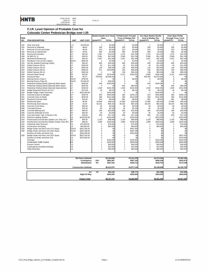
F.I.R. Level Opinion of Probable Cost for Colorado Center Pedestrian Bridge over I-25
ITEMNO. ITEM DESCRIPTION UNIT UNIT COST QUANTITY TOTAL QUANTITY TOTAL QUANTITY TOTAL QUANTITY TOTAL
202 Clear and Grub L S $2,000.00 1 $2,000 1 $2,000 1 $2,000 1 $2,000202 Removal of Sidewalk SY $8.00 350 $2,800 350 $2,800 350 $2,800 350 $2,80020 Removal of Curb and Gutter LF $4.00 510 $2,040 510 $2,040 510 $2,040 510 $2,040202 Removal of Asphalt Mat SY $3.00 800 $2,400 800 $2,400 800 $2,400 800 $2,400206 Structural Excavation CY $10.00 1,351 $13,510 1,476 $14,760 1,476 $14,760 1,476 $14,760206 Str Bkfl (CL 1) CY $20.00 2,381 $47,620 2,589 $51,780 2,589 $51,780 2,589 $51,780206 Mechanical Reinforcing CY $20.00 1,567 $31,340 1,567 $31,340 1,567 $31,340 1,567 $31,340214 Deciduous Tree (2 Inch Caliper) EACH $500.00 2 $1,000 2 $1,000 2 $1,000 2 $1,000403 Hot Mix Asphalt (Patching) (Asph) SY $50.00 900 $45,000 900 $45,000 900 $45,000 900 $45,000503 Drilled Caisson (36 In) LF $250.00 45 $11,250 45 $11,250 45 $11,250 45 $11,250503 Drilled Caisson (42 In) LF $300.00 118 $35,400 118 $35,400 118 $35,400 118 $35,400503 Drilled Caisson (48 In) LF $350.00 371 $129,850 160 $56,000 160 $56,000 160 $56,000503 Drilled Caisson (54 In) LF $400.00 0 $0 138 $55,200 138 $55,200 138 $55,200509 Precast Panel Facing SF $20.00 8,923 $178,460 9,131 $182,620 9,008 $180,160 9,131 $182,620509 Structural Steel LB $3.75 759,818 $2,849,318 0 $0 500,000 $1,875,000 0 $0512 Bearing Device (Type I) EACH $750.00 0 $0 8 $6,000 8 $6,000 8 $6,000512 Bearing Device (Type III) EACH $7,500.00 4 $30,000 0 $0 0 $0 0 $0514 Pedestrian Railing (Steel) (Special) (Main Span) LF $250.00 640 $160,000 0 $0 640 $160,000 0 $0514 Pedestrian Railing (Steel) (Special) (Main Span) LF $100.00 0 $0 640 $64,000 0 $0 640 $64,000514 Pedestrian Railing (Steel) (Special) (Approaches) LF $150.00 1,549 $232,350 1,549 $232,350 1,549 $232,350 1,549 $232,350518 Bridge Expansion Device (0-4 In) LF $175.00 35 $6,125 35 $6,125 35 $6,125 35 $6,125520 Bridge Hanger Cable Assembly L S $155,000.00 1 $155,000 0 $0 1 $155,000 0 $0601 Concrete (Class D) (Bridge) CY $430.00 662 $284,660 384 $165,120 616 $264,880 384 $165,120601 Concrete Class D (Wall) CY $430.00 306 $131,580 306 $131,580 306 $131,580 306 $131,580602 Structural Concrete Stain SY $10.00 943 $9,430 881 $8,810 881 $8,810 881 $8,810602 Reinforcing Steel LB $0.90 40,569 $36,512 27,800 $25,020 27,800 $25,020 27,800 $25,020602 Reinforcing Steel (Epoxy) LB $1.00 94,181 $94,181 65,325 $65,325 65,325 $65,325 65,325 $65,325608 Concrete Curb Ramp SY $90.00 28 $2,520 28 $2,520 28 $2,520 28 $2,520608 Truncated Domes SF $70.00 30 $2,100 30 $2,100 30 $2,100 30 $2,100608 Concrete Bikeway (6") SY $50.00 300 $15,000 300 $15,000 300 $15,000 300 $15,000608 Concrete Sidewalk (6 Inch) SY $50.00 40 $2,000 40 $2,000 40 $2,000 40 $2,000609 Curb and Gutter Type 2 (Section II-B) LF $18.00 950 $17,100 950 $17,100 950 $17,100 950 $17,100613 Electrical Lighting System LS $125,000.00 1 $125,000 1 $125,000 1 $125,000 1 $125,000618 Prestressed Concrete Box (Depth Less Than 32") SF $45.00 2,220 $99,900 2,220 $99,900 2,220 $99,900 2,220 $99,900618 Prestressed Concrete Box (Depth Greater Than 48") SF $65.00 1,680 $109,200 1,680 $109,200 1,680 $109,200 1,680 $109,200621 Pedestrian Stair Structure LS $75,000.00 1 $75,000 1 $75,000 1 $75,000 1 $75,000625 Construction Surveying LS $50,000.00 1 $50,000 1 $50,000 1 $50,000 1 $50,000628 Bridge Girder and Deck Unit (170' Span) EACH $451,350.00 0 $0 1 $451,350 0 $0 0 $0628 Bridge Girder and Deck Unit (150' Span) EACH $387,188.00 0 $0 1 $387,188 0 $0 0 $0
Erection of Girder and Deck Unit LS $325,000.00 0 $0 1 $325,000 0 $0 0 $0628 Bridge Girder and Deck Unit (320' Span) EACH $937,420.00 0 $0 0 $0 0 $0 1 $937,420
Erection of Girder and Deck Unit LS $375,000.00 0 $0 0 $0 0 $0 1 $375,000Drainage LS 1 $150,000 1 $150,000 1 $150,000 1 $150,000Construction Traffic Control LS 1 $100 000 1 $200 000 1 $200 000 1 $200 000
Prefabricated Through-Truss w/ Median Pier
Basket Handle Arch Clear Span
Two Span Basket Handle Arch w/ Median Pier
Clear Span Prefab Through Truss / Arch
Construction Traffic Control LS 1 $100,000 1 $200,000 1 $200,000 1 $200,000Erosion Control LS 1 $40,000 1 $40,000 1 $40,000 1 $40,000Landscaping (Including Seeding) LS 1 $15,000 1 $15,000 1 $15,000 1 $15,000Utility Relocates LS 1 $50,000 1 $50,000 1 $50,000 1 $50,000
Bid Items Subtotal $5,344,646 $3,314,278 $4,374,040 $3,463,160Contingency 15% $801,697 $497,142 $656,106 $519,474Mobilization 5% $267,232 $165,714 $218,702 $173,158
Construction Subtotal $6,413,575 $3,977,134 $5,248,848 $4,155,792
Art 1% $64,136 $39,771 $52,488 $41,558Right Of Way $250,000 $250,000 $250,000 $250,000
Project Total $6,727,710 $4,266,905 $5,551,336 $4,447,350
CCD_Ped_Bridge_Opinion_of_Probable_Cost(Dec10).xls Page 1 11:10 AM8/25/2011

APPENDIX I:
STRUCTURE TYPE ALTERNATIVES - SITE PLAN & DETAILS

5410
5420
5430
5440
5450
5460
5470
5480
5490
5500
5510
5410
5420
5430
5440
5450
5460
5470
5480
5490
5500
5510
From Colorado
Center Drive
12+00
11+00 13+00
P.I. S
ta. 13
+09.2
5
Curb
Curb
Walk
PLAN
SECTION
30:1
Existing
Ground Line
HCL & PGL
10’-
0"
1’-
3"
1’-
3"
12’-
6"
13+0012+0011+00
Sta. 12+25.00
Elev. 5432.94
Sta. 12+20.00
Elev. 5432.89Sta. 11+85.00
Elev. 5430.38
Sta. 11+55.00
Elev. 5427.92
Sta. 11+50.00
Elev. 5427.87
Sta. 11+20.00
Elev. 5425.41
Sta. 11+15.00
Elev. 5425.36
Sta. 11+90.00
Elev. 5430.43
Sta. 12+55.00
Elev. 5435.40
Sta. 12+60.00
Elev. 5435.45
Sta. 12+89.00
Elev. 5437.77
Sta. 10+85.00
Elev. 5422.90
Sta. 10+80.00
Elev. 5422.85
Sta. 10+50.00
Elev. 5420.39
S72̂ 28’07"E S83^30’17"E
Landing, Typ.
Bottom of FootingElev. 5414.75 (Level)
B.F. Abut. 1
Sta. 13+25.00
Begin Structure
Sta. 10+50.00
Begin Structure
Sta. 10+50.00
(Taken along HCL)* Elevations at Top of Finished Grade @ PGL
Grade Break, Typ.
Bottom of Footing
Elev. 5416.75 (level)Bottom of Footing
Elev. 5415.75 (level)
Ò Brg. Abut. 1
End Structure
Sta. 13+26.00
Sta. 13+26.00
Elev. 5438.20
5400 5400
W. Moy
06/11
XX
XM
M/
YY
AJP
06/11
WM
08/11
WM
08/11
XX
XM
M/
YY
WM
OY
GENERAL LAYOUT (1 OF 4)
A. Price
Bridge B3
1:30
Ò Brg. Abut. 1
Sta. 13+26.00
N44^05’3
4"E
N44̂ 05’34"E
Ò Type C Inlets
Sta. 10+53.00
Existing Underground
Electric (to be relocated)
Existing Water UtilityExisting Water Utility
Existing Transmission
TowerExisting Electric
Transformer
Existing Underground
Electric (to be relocated)
Existing Overhead Electric
Existing Wall, Typ.
Existing Storm
Water Manhole
PGL
PGL
Existing Overhead
Electric Existing Underground
Electric
P.I. Sta. 13
+09.2
5
Span 1
38’-0"
P.I. S
ta. 1
1+05.6
8
P.I.
Sta. 11+05.6
8
Pedestrain Railing, Typ.
Pedestrain Railing, Typ.
168^57’49" 127^35’52"
90^00’00"
127^35’52"
HCL
HCL
E
Back Face Abut. 1
276’-0" Begin Ramp to Ò Abut. 1
Existing UndergroundElectric
INITIA
L
Desig
n
Desig
ned
By
Checked
By
DA
TE
DA
TE
DA
TE
INITIA
LINITIA
L
Detail
Quantities
Detailed
By
Checked
By
Checked
By
Quantities
By
Numbers
Structure
No Revisions:
Revised:
Void: Sheet Subset:
Detailer:
Designer:
Sheet NumberSubset Sheets:
Init.CommentsDate:
Sheet Revisions As Constructed
19-AUG-2011Print Date:
Horiz. Scale:
49589BRDG_GNLAY01.dgn
Unit Leader Initials
Project No./CodeFile Name:
Staff Bridge Branch - Unit 022X
\\
den
w00\
ho
me2proj\
49589
CC
D
Colorado
Center Ped
Brid
ge\
TE
CH
PR
OD\
CD\
BR
DG\
49589
BR
DG
_G
NL
AY
01.d
gn
of
City and County of Denver
201 W. Colfax Ave.
Denver, CO 802021600 Broadway, Suite 1300 Ph# 303-839-8300
Denver, Colorado 80202 Fax 303-839-9800
Vert. Scale:
17954
STE 0252-411
PEDESTRIAN BRIDGE OVER I-25
F-17-NY
T
5420.495489.39
MID INS AT POLE
T
X
SHOT CL POLE
5420.99
ST
5422.03X
ST
5421.36
X5480.23X
5480.27
X
5410
5420
5430
5440
5450
5460
5470
5480
5490
5500
5510
5410
5420
5430
5440
5450
5460
5470
5480
5490
5500
5510
Fro
m
Colorado
Center Drive
15+0014+00 16+00
17+00
13+00
P.I. Sta. 13
+09.2
5
I-25
Southbound
Ra
mp
Ra
mp
Ra
mp
I-25
Northbound
Ra
mp
Curb
Curb
12’-
3"
Walk
90^00’00", Typ.
SECTION
14+00 15+00 16+00
Ramp
RampRamp
Ramp
I-25 SouthboundI-25 Northbound
671’-6"
19’-
3"
30:1
+1.22%
Span 2
18’-
6"
Min.
18’-
1"
Min.
Vert.
Cle
ar.
(Actual)
Vert.
Cle
ar.
(Actual)
Existing
Ground Line
B.F. Abut. 1
309’-0"
Span 1
38’-0"
Ò Pier 3
& Matchline
Sta. 16+73.00
Ò Brg. Abut. 1
B.F. Abut. 1 to B.F. Abut. 7
+1.22%
N 44^05’34.16" E
Ò Pier 2
Ò Pier 3,
& Matchline
5.36%
1’-0"
HCL & PGL
Elev. 5444.00
Elev. 5438.19Elev. 5440.24
Ò Pier 2
Sta. 13+64.00
B.F. Abut. 1
Sta. 13+25.00
136’-0"
Span 3
P.I. Sta. 16+73.0
0
Ò Tie Girder, Typ.
6"
6"
PLAN
JG
B04/11
XX
XM
M/
YY
AJP
05/11
TF
K08/11
AL
S08/11
XX
XM
M/
YY
GENERAL LAYOUT (2 OF 4)
J. Guenther
A. Price
Bridge B4
30:1
B76
EF
F
EE
18" Storm SewerAbandoned Waterline
remove at contractors
option
Prefabricated Bridge Girder and Deck Unit
14’-
6"
Min.
Vert.
Clr
Proposed Ground Line
Pedestrian Railing, Typ.
Crown Line
1.00%
INITIA
L
Desig
n
Desig
ned
By
Checked
By
DA
TE
DA
TE
DA
TE
INITIA
LINITIA
L
Detail
Quantities
Detailed
By
Checked
By
Checked
By
Quantities
By
Numbers
Structure
No Revisions:
Revised:
Void: Sheet Subset:
Detailer:
Designer:
Sheet NumberSubset Sheets:
Init.CommentsDate:
Sheet Revisions As Constructed
19-AUG-2011Print Date:
Horiz. Scale:
49589BRDG_GNLAY02.dgn
Unit Leader Initials
Project No./CodeFile Name:
Staff Bridge Branch - Unit 022X
\\
den
w00\
ho
me2proj\
49589
CC
D
Colorado
Center Ped
Brid
ge\
TE
CH
PR
OD\
CD\
BR
DG\
49589
BR
DG
_G
NL
AY
02.d
gn
of
City and County of Denver
201 W. Colfax Ave.
Denver, CO 802021600 Broadway, Suite 1300 Ph# 303-839-8300
Denver, Colorado 80202 Fax 303-839-9800
Vert. Scale:
17954
STE 0252-411
PEDESTRIAN BRIDGE OVER I-25
F-17-NY
13+00
14
+00
15
+00
16
+00
ST
1+00 2
+00
2+29


5410
5420
5430
5440
5450
5410
5420
5430
5440
5450
18+0017+00
P.I.
Sta.
16
+7
3.0
0
14’-
9"
SECTION18+0017+00 19+00 20+00
P.I.
Sta.
18
+09.0
0
1’-
3"
Curb
1’-
3"
Curb
12’-
3"
Walk
P.I.
Sta.
18
+09.0
0
18
+00
PARTIAL PLAN PARTIAL PLAN
To E.
Jewell Ave.
19+00 20+00
1’-
3"
Curb
1’-
3"
Curb
Walk
12’-
6"
10’-
0"
HCL & PGL
Cherry St.
136’-0" 51’-0" 67’-6" 67’-6" 1’-6"
-8.20% -1.00%
-8.20%-1.00%
-8.20%
-8.20%
90^00’00",
Typ. UNO
Span 3 Span 4 Span 5 Span 6
Ò Pier 5 Ò Pier 6 B.F. Abut. 7
Existing
Ground Line
Bend Line
Pedestrian Railing, Typ.
-1.00%-1.57%
Ò Pier 5
Sta. 18+60.00
Ò Pier 6
Sta. 19+27.50
B.F. Abut. 7
Sta. 19+96.25HCL & PGL60^48’31"
Ò Pier 3
& Matchline
Sta. 16+73.00
53^08’11"
Ò Pier 4
& Matchline
Sta. 18+09.00
Ò Pier 4
& Matchline
Sta. 18+09.00
N 44
^05’34.16" E
N 73^17’3.66" E N 00^26’33.98" W
53^08’11"
671’-6"
B.F. Abut. 1 to B.F. Abut. 7
671’-6"
B.F. Abut. 1 to B.F. Abut. 7
SECTION
Existing
Ground Line
Ò Pier 3 & Matchline Ò Pier 4 & Matchline
Ò Pier 4 & Matchline
Elev. 5444.00 Elev. 5438.20
Elev. 5432.41Elev. 5427.41
Elev. 5437.40
1:30
Grade Break, Typ.
SlopeVaries
-4.26% SlopeVaries
NOTES:
1. See Construction Layouts for location of grade breaks.
Grade Break, Typ.
Ò Brg. Abut. 7
JB
G05/11
XX
XM
M/
YY
AJP
05/11
TF
K08/11
AL
S08/11
XX
XM
M/
YY
GENERAL LAYOUT (3 OF 4)
J. Guenther
A. Price
Bridge B5 B76
1:30
Ò Stair Piers
EE
FF
FF
F F
F F
E
13’-
5"
12’-
2"
14’-
9�
"
14’-
10"
10’-
9"
6’-
6"
Min.
Vert.
Clr.
Min.
Vert.
Clr.
Min.
Vert.
Clr.
Min.
Vert.
Clr.
Min.
Vert.
Clr.
Min.
Vert.
Clr.
Pedestrian Railing, Typ.
Crown LineCrown Line
-1.00%
INITIA
L
Desig
n
Desig
ned
By
Checked
By
DA
TE
DA
TE
DA
TE
INITIA
LINITIA
L
Detail
Quantities
Detailed
By
Checked
By
Checked
By
Quantities
By
Numbers
Structure
No Revisions:
Revised:
Void: Sheet Subset:
Detailer:
Designer:
Sheet NumberSubset Sheets:
Init.CommentsDate:
Sheet Revisions As Constructed
19-AUG-2011Print Date:
Horiz. Scale:
49589BRDG_GNLAY03.dgn
Unit Leader Initials
Project No./CodeFile Name:
Staff Bridge Branch - Unit 022X
\\
den
w00\
ho
me2proj\
49589
CC
D
Colorado
Center Ped
Brid
ge\
TE
CH
PR
OD\
CD\
BR
DG\
49589
BR
DG
_G
NL
AY
03.d
gn
of
City and County of Denver
201 W. Colfax Ave.
Denver, CO 802021600 Broadway, Suite 1300 Ph# 303-839-8300
Denver, Colorado 80202 Fax 303-839-9800
Vert. Scale:
17954
STE 0252-411
PEDESTRIAN BRIDGE OVER I-25
F-17-NY
17
+00
18
+00
19
+00
20
+00
SASASA

Ò Bridge
13’-3"
HCL &
PGL
Bridge
Strand, Typ.
Ò Tie Girder &
Arch Rib, Typ.
Ò Arch Ribs
TYPICAL SECTION (OVER I-25)
6’-1�"
14’-9"
1’-3" 1’-3"6’-1�"
HCL &
PGL
4’-
6"
Typ.
Ò Bridge
4’-
6"
Typ. HCL &
PGL
12’-6"
1’-3" 5’-0" 1’-3"5’-0"
Ò Bridge
TYPICAL SECTION (APPROACH SPANS)
Pedestrian
Railing, Typ.
Pedestrian
Railing, Typ.
As Noted
Scale: �"=1’-0"
Scale: �"=1’-0"
48" x 60" Prestressed
Concrete Box Girder, Typ.
SPAN 2
48" x 24" Prestressed
Concrete Box Girder, Typ.
SPAN 3
6’-1�"
14’-9"
1’-3" 1’-3"6’-1�"
HCL &
PGL
4’-
6"
Typ.
Ò Bridge
Pedestrian
Railing, Typ.
48" x 18" Prestressed
Concrete Box Girder, Typ.
SPAN 1
Varies
SPANS 4, 5 AND 6
6’-1�" 6’-1�" 30’-
0"
Min.
@
Apex.
4’-
0"
Max.
PGL
Low Point of Structure
6" 6"
9’-7�" 9’-7�"
19’-3"
Pedestrian
Handrail/Rubrail, Typ.
As Noted
JB
G05/11
XX
XM
M/
YY
AJP
05/11
TF
K08/11
AL
S08/11
XX
XM
M/
YY
TYPICAL SECTIONS
J. Guenther
A. Price
Bridge B7 B76
2%2%
2%2%
2%2%
2%2%
PREFABRICATED BRIDGE GIRDER AND DECK UNIT
Ò Floor Beams
INITIA
L
Desig
n
Desig
ned
By
Checked
By
DA
TE
DA
TE
DA
TE
INITIA
LINITIA
L
Detail
Quantities
Detailed
By
Checked
By
Checked
By
Quantities
By
Numbers
Structure
No Revisions:
Revised:
Void: Sheet Subset:
Detailer:
Designer:
Sheet NumberSubset Sheets:
Init.CommentsDate:
Sheet Revisions As Constructed
19-AUG-2011Print Date:
Horiz. Scale:
49589BRDG_TYPSECT-Bridge.dgn
Unit Leader Initials
Project No./CodeFile Name:
Staff Bridge Branch - Unit 022X
\\
den
w00\
ho
me2proj\
49589
CC
D
Colorado
Center Ped
Brid
ge\
TE
CH
PR
OD\
CD\
BR
DG\
49589
BR
DG
_T
YP
SE
CT-
Brid
ge.d
gn
of
City and County of Denver
201 W. Colfax Ave.
Denver, CO 802021600 Broadway, Suite 1300 Ph# 303-839-8300
Denver, Colorado 80202 Fax 303-839-9800
Vert. Scale:
17954
STE 0252-411
PEDESTRIAN BRIDGE OVER I-25
F-17-NY
