structure response study crystal ridge, … response study crystal ridge, macdonald ranch, and...
TRANSCRIPT

Structure Response Study Crystal Ridge, MacDonald Ranch, and MacDonald Highlands For the City of Henderson 240 Water St. Henderson, Nevada Prepared by Dr. Catherine T. Aimone-Martin President May 27, 2005
AIMONE-MARTIN ASSOCIATES LLC 1005 BULLOCK AVE.
SOCORRO, NM 87801
(505) 838-2229

AUTHOR BIOGRAPHY Dr. Aimone-Martin is President of Aimone-Martin Associates, LLC and a Professor Mining and Civil Engineering at New Mexico Institute of Mining and Technology. She has degrees in geological engineering (with emphasis in geophysics and mining), civil engineering, and mining engineering. Since 1971, she has worked in the mining and construction industries and with geotechnical consulting firms in both the U.S. and Canada, and with Sandia and Los Alamos National Laboratories as a research affiliate. Special projects with national laboratories have included research on electrohydraulic fracture, design of underground nuclear repositories, and solar-powered solution mining concepts for potash extraction. Dr. Aimone-Martin helped to fund for the development of the Center of Explosives Technology and Research at New Mexico Tech with a $5M grant and was Chair of the Mining, Geological, and Environmental Engineering Department for 9 years. She currently serves as an advisor to Homeland Security and on several national committees and boards including the National Institute of Occupational Health under NIH and the New Mexico Mining Association Board of Directors. She has recently held important U.S. Presidential appointments to the Academy of Sciences of the National Research Council. Dr. Aimone-Martin served 13 years as a Director on the International Society of Explosives Engineering Board (ISEE) and continues to participate on Committees including Seismograph Standards Committee, Public Relations, and Education. Dr. Aimone-Martin is an international invited speaker, author of over 90 publications, and has received over $500,000 in research grants while at New Mexico Tech. Dr. Aimone-Martin’s expertise is in the areas of explosives engineering, rock blasting, structure response to blasting, instrumentation for vibration control and structure response, geotechnical engineering, soil and rock mechanics, foundation design and analysis, risk assessments, regulatory compliance, and public relations. She serves as a consultant to construction, coal, quarrying, and hard rock mining companies in the areas of blast design, vibration monitoring and control, structure response, fragmentation, backbreak control, instrumentation, blasting impact plans, and public relations. Dr. Aimone-Martin has further worked for municipalities in the development of blasting standards and regulations to protect off-site structures and for federal agencies to validate federal safe blasting standards limiting vibration and airblast for general blasting applications throughout the U.S.

Structure Response Study Aimone-Martin Associates, LLC
1
Sun CityMacDonald
Ranch
West Horiz
on RidgeMacDonald HighlandsBLASTING
AREABrennan Brothers
BLASTING AREA
Crystal RidgeBLASTING
AREA
Roma Hills
A
B
A High MesaB Bighorn
Sun CityMacDonald
Ranch
West Horiz
on RidgeMacDonald HighlandsBLASTING
AREABrennan Brothers
BLASTING AREA
Crystal RidgeBLASTING
AREA
Roma Hills
Sun CityMacDonald
Ranch
West Horiz
on RidgeMacDonald HighlandsBLASTING
AREABrennan Brothers
BLASTING AREA
Crystal RidgeBLASTING
AREA
Roma Hills
A
B
A High MesaB Bighorn
INTRODUCTION
The response of two residential structures to blasting vibrations was conducted in Henderson, NV from March 15 to April 15, 2005. The location and identification of the residential structures are shown in Figure 1. Structure ‘A’ is location at the corner of High Mesa Drive and Cyprus Mesa Drive in Sun City MacDonald Ranch. Structure ‘B’ is located on Bighorn in MacDonald Highlands. Both structures are wood-framed with stucco exteriors. Structure ‘B’ is a single-story, slab-on-grade dwelling and the two-story structure ‘A’ is constructed into the hillside.
Structures were instrumented with single-axis velocity geophones to measure whole structure and mid-wall vibratory motions during blasting events. Displacement-type gages were used to measure the motions of an existing exterior wall crack. A single tri-axial geophone, buried in the ground, and an air pressure sensor were employed exterior to the dwellings to record ground motions and airblast. Data analyses for blast-induced motions were conducted to:
• compare vibration time histories in terms of velocity and calculated displacements within structures relative to ground excitations and air overpressures
• evaluate response frequencies to determine natural frequencies and damping
characteristics
• determine structure response amplification of ground motions
• compute differential displacements at corner motions to estimate global shear and in-plane tension wall strains, and
• compute bending strains in walls
Figure 1 Location map showing blast sites and structures used for instrumentation Corner and mid-wall motions from blasting were compared with motions induced by external

Structure Response Study Aimone-Martin Associates, LLC
2
forces such as wind and construction activities taking place adjacent to residential structures. In addition, wall crack responses (e.g., crack opening and closing) to environmental changes, wind, construction and blasting vibrations were measured.
The large volume of supporting data summaries and plot are found in the Appendices organized as follows:
Appendix A Blasting seismograph records for structure at High Mesa B Blasting seismograph records for structure at Bighorn C Seismograph records during construction activities and wind for structures at Bighorn and High Mesa D Summary of seismograph data
E Displacement time histories and strain calculations F Crack displacement time histories for High Mesa structure G Crack displacement time histories for Bighorn structure
PROCEDURES Vibration and Airblast Instrumentation
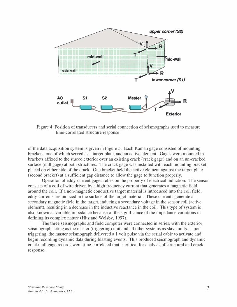
Figures 2 and 3 show the exterior instrumentation locations at the two structures. The locations of the single component velocity transducers placed in the upper (S2) corner, lower (S1) corner, and at the mid-wall (MW) are indicated. LARCOR� multi-component seismographs were used to digitally record four channels of seismic data. The exterior (master) unit consisted of a tri-axial geophone and an airblast microphone. The geophones, buried 4 in. in depth, were oriented so that the radial, R, component was parallel with the longest axes of the house. This orientation is based upon recording motions that are parallel to one of the house’s translation axes rather than the traditional direction relative to the vibration source. The airblast microphone was installed 4 to 6 in. above the ground surface and used to record the pressure pulses transmitted through the air during blasting.
Both the S1 and S2 seismographs were connected to clusters of three single axis transducers in the upper and lower exterior corners closest to the blasting activity and at the mid-wall of the adjoined walls as shown in Figures 2 and 3. The three seismographs were connected in series, with the exterior seismograph acting as the master (triggering) unit and all other systems as slave units generically shown in Figure 4. These transducers were affixed to the walls using hot glue to minimize damage during removal. The three corner transducers measured whole structure motions in the horizontal radial, transverse, and vertical directions. The mid-wall transducers measured horizontal motions during wall flexure or bending.
Existing Crack Gage Instrumentation
To measure the effect of blasting and climate conditions (temperature and humidity) on changes in the width of existing exterior cracks, Kaman� eddy-current gages were installed, as shown in Figures 2 and 3, and data was collected using a SOMAT� field computer. A schematic
Structure Response Study Aimone-Martin Associates, LLC
3
R
V
TExterior
ACoutlet
S1 S2 Master
RV
T
RV
T
upper corner (S2)
lower corner (S1)
mid-wall mid-wall
radial wall
R
V
TExterior
ACoutlet
S1 S2 Master
RV
T
RV
T
upper corner (S2)
lower corner (S1)
mid-wall mid-wall
R
V
TExterior
ACoutlet
S1 S2 Master
RV
T
RV
T
upper corner (S2)
lower corner (S1)
mid-wall mid-wall
radial wall
Figure 4 Position of transducers and serial connection of seismographs used to measure time-correlated structure response
of the data acquisition system is given in Figure 5. Each Kaman gage consisted of mounting brackets, one of which served as a target plate, and an active element. Gages were mounted in brackets affixed to the stucco exterior over an existing crack (crack gage) and on an un-cracked surface (null gage) at both structures. The crack gage was installed with each mounting bracket placed on either side of the crack. One bracket held the active element against the target plate (second bracket) at a sufficient gap distance to allow the gage to function properly.
Operation of eddy-current gages relies on the property of electrical induction. The sensor consists of a coil of wire driven by a high frequency current that generates a magnetic field around the coil. If a non-magnetic conductive target material is introduced into the coil field, eddy-currents are induced in the surface of the target material. These currents generate a secondary magnetic field in the target, inducing a secondary voltage in the sensor coil (active element), resulting in a decrease in the inductive reactance in the coil. This type of system is also known as variable impedance because of the significance of the impedance variations in defining its complex nature (Hitz and Welsby, 1997).
The three seismographs and field computer were connected in series, with the exterior seismograph acting as the master (triggering) unit and all other systems as slave units. Upon triggering, the master seismograph delivered a 1 volt pulse via the serial cable to activate and begin recording dynamic data during blasting events. This produced seismograph and dynamic crack/null gage records were time-correlated that is critical for analysis of structural and crack response.

Structure Response Study Aimone-Martin Associates, LLC
4
Figure 5 Displacement gage system used to measure opening and closing of an existing wall crack (above) and close-up of mounted crack gage (below)
crack nullgage 1 gage 2
gagepower supply
split in cable
powertrigger
gage 1gage 2
to computer
Somatfieldcomputer
Computer
exteriorseismograph
signal signalconditioner conditioner
1 2
crack nullgage 1 gage 2
gagepower supply
split in cable
powertrigger
gage 1gage 2
to computer
Somatfieldcomputer
Computer
exteriorseismograph
signal signalconditioner conditioner
1 2
active element
existing wall crack

Structure Response Study Aimone-Martin Associates, LLC
5
The master and slave seismographs each had a range of available settings for recording data. These settings include:
• trigger levels for the master unit set to 0.03 in. per second (ips) for ground velocity, and 125 decibels (dB) for airblast
• sample rate set at 512 samples per second • a sampling duration of 9 (one-story house on High Mesa) to 12 seconds (the two-story
house on Bighorn) These settings ensured the full data record was preserved with sufficient resolution.
The Kaman gage system was programmed to sample crack opening and closing every hour in response to diurnal environmental changes. In the dynamic or ‘burst’ mode, data was acquired every 0.001 seconds. Temperature and relative humidity were recorded using a SUPCO� data logger. A sample interval of 10 minutes was used.
The operating parameters of the Kaman gages are as follows:
• displacement monitoring range of 0.02 inches. • output voltage range ± 5 volts. • resolution of 3.94 micro-inch. (.00000394 in.) • frequency response of 10,000 Hertz (Hz).
Throughout this report, readers are reminded that the velocity unit of inches per second (ips)
is one only of convenience. Neither the ground nor the structures move in inches over time but rather milli-inches per milli-second. Structure damage in the form of cosmetic or threshold wall cracks do not result from high structure velocities, but rather high differential displacements in walls leading to high strains or strains that exceed the failure strain of the materials comprising the walls. Therefore the analysis herein emphasizes structure and wall strains as an indicator of potential damage to structures. Data Analysis
Velocity data were analyzed using White 2000� software to plot velocity and displacement time histories and integrate velocity time histories. Two frequencies, or wave cycles (oscillations) per second, are of interest and were analyzed. The peak frequency is that frequency associated with the maximum velocity amplitude over the full time-history of motion. It is used to demonstrate compliance with frequency-based regulations. The predominant frequency, evaluated using Fast Fourier Transform (FFT) analysis, dominates over the entire time history. The FFT frequency carried the largest percentage of ground motion energy and is important when evaluating structure response.
Crack gage data were downloaded from the SOMAT� field computer and analyzed using SOMAT WINTCS v.2.0.1 and SOMAT� DataXplorer v. 3 softwares. Crack displacement time histories were filtered using Data Filter, (Mercer, 2002) a spectrum filtering program to remove system noise and enhance the data signal-to-noise ratio.

Structure Response Study Aimone-Martin Associates, LLC
6
PPV = 121.6 SD-1.50
R2 = 0.93
0.01
0.10
1.00
10.00
1 10 100 1000
SCALED DISTANCE (D/W1/2) (ft/lb1/2)
PE
AK
VE
LOC
ITY
(in/
s) B
Structure response study
Attenuation study
outlyer measuredon 3/23/05
RESULTS
Seismograph reports are given in Appendices A through C. Appendix D contains summary tables of all velocity and airblast values for the various seismographs. Data are given by blast date and include peak velocity values and frequencies for the three components of ground motion and for the single component interior geophones. Information on the blasts such as distance from the structure to each blast and the explosive charge weights per delay have been previously given in the report “Blasting Attenuation Study” (Aimone-Martin, 2005). Ground Motion and Airblast
Figures 6 and 7 are plots of scaled distance factor plotted against peak ground motions and airblast, respectively. Data recorded during the structure response study at the two dwellings are compared with data collected during the attenuation study. The attenuation study included very close-in measurements (up to 40 ft. from the blasts) to better define attenuation slopes taking into account both distance form the blast and the explosive charge weights used in design. Scaled distance factors are applied to ground motions and airblast, given by the following:
Square-root scaled distance 2/1WD
SRSD = ground motion (1)
Cube-root scaled distance 3/1W
DCRSD = airblast (2)
Figure 6 Peak particle velocity in the ground versus scaled distance for structure response study compared with data recorded during attenuation study

Structure Response Study Aimone-Martin Associates, LLC
7
AIR = 181.1 CRSD-0.089
R2 = 0.87
90
100
110
120
130
140
10 100 1000
SCALED DISTANCE (D/W1/3) (ft/lb1/3)
AIR
BLA
ST
(dB
) B
Structure response study
Attenuation study
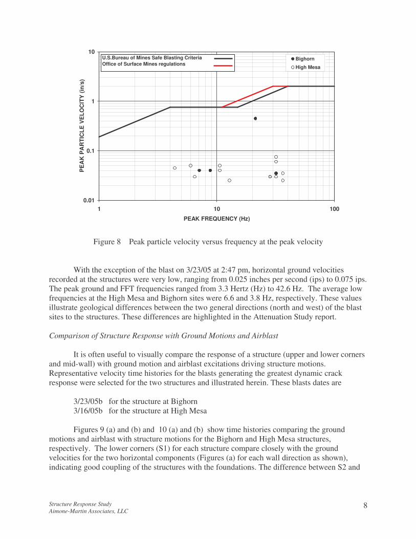
Figure 7 Peak airblast versus cube-root scaled distance for structure response study compared with data recorded during attenuation study where D is the shot-to-seismograph distance and W is the maximum charge weight detonated within any 8 ms time period (referred to as one delay time period). Scaled distance is a means of incorporating the two most important factors contributing to the intensity of ground motion and airblast as intensity decreases proportionally with distance and inversely with the explosive weight detonated on one time delay. In the case of ground motion, the SRSD is used (commonly referred to as simply SD) as ground motion has been shown to correlate with the square root of the charge weight. In the case of airblast, air pressures correlate best with the cube-root of the charge weight. Values for PPV and airblast during this study plot below the current limits (0.5 ips and 120 dB). The outlyer data point for the 3/23/05 blast at 2:47 pm in Figure 6 was discussed in the attenuation study and may be the results of errors associated with explosive charge weight reported. Figure 8 is a plot of the peak particle velocities (PPV) and frequency of ground motion at the PPV. The data for ground motions at the two structures are plotted within the safe blasting criteria recommended by the U.S. Bureau of Mines and surface coal mining regulatory limits, as enforced by the Office of Surface Mining (OSM). All data recorded during this study fell well within the safe blasting criteria for which no damage to structures can occur with a 100% confidence. This safe criteria is based on over 40 years of research and crack observations that have never been scientifically challenged.
Structure Response Study Aimone-Martin Associates, LLC
8
0.01
0.1
1
10
1 10 100
PEAK FREQUENCY (Hz)
PE
AK
PA
RTI
CLE
VE
LOC
ITY
(in/
s)
Bighorn
High Mesa
U.S.Bureau of Mines Safe Blasting CriteriaOffice of Surface Mines regulations
Figure 8 Peak particle velocity versus frequency at the peak velocity
With the exception of the blast on 3/23/05 at 2:47 pm, horizontal ground velocities recorded at the structures were very low, ranging from 0.025 inches per second (ips) to 0.075 ips. The peak ground and FFT frequencies ranged from 3.3 Hertz (Hz) to 42.6 Hz. The average low frequencies at the High Mesa and Bighorn sites were 6.6 and 3.8 Hz, respectively. These values illustrate geological differences between the two general directions (north and west) of the blast sites to the structures. These differences are highlighted in the Attenuation Study report. Comparison of Structure Response with Ground Motions and Airblast
It is often useful to visually compare the response of a structure (upper and lower corners and mid-wall) with ground motion and airblast excitations driving structure motions. Representative velocity time histories for the blasts generating the greatest dynamic crack response were selected for the two structures and illustrated herein. These blasts dates are 3/23/05b for the structure at Bighorn 3/16/05b for the structure at High Mesa
Figures 9 (a) and (b) and 10 (a) and (b) show time histories comparing the ground motions and airblast with structure motions for the Bighorn and High Mesa structures, respectively. The lower corners (S1) for each structure compare closely with the ground velocities for the two horizontal components (Figures (a) for each wall direction as shown), indicating good coupling of the structures with the foundations. The difference between S2 and

Structure Response Study
Aim
one-Martin A
ssociates, LLC
9
SW wall
-0.6
0.0
0.6
0.5 1.5 2.5Time (s)
Vel
ocity
(in/
s)
GVS1
SE wall
-0.6
0.0
0.6
0.5 1.5 2.5Time (s)
Vel
ocity
(in/
s)
GVS1
SW wall
-0.6
0.0
0.6
0.5 1.5 2.5Time (s)
Vel
ocity
(in/
s)
S2S1
SE wall
-0.6
0.0
0.6
0.5 1.5 2.5
Time (s)
Vel
ocity
(in/
s)
S2S1
-0.004
0.000
0.004
0.5 1.5 2.5
Time (s)
Air
Pre
ssu
re (p
si)
SW wall
-0.6
0.0
0.6
0.5 1.5 2.5Time (s)
Vel
ocity
(in/
s)
GVS1
SE wall
-0.6
0.0
0.6
0.5 1.5 2.5Time (s)
Vel
ocity
(in/
s)
GVS1
SW wall
-0.6
0.0
0.6
0.5 1.5 2.5Time (s)
Vel
ocity
(in/
s)
S2S1
SE wall
-0.6
0.0
0.6
0.5 1.5 2.5
Time (s)
Vel
ocity
(in/
s)
S2S1
-0.004
0.000
0.004
0.5 1.5 2.5
Time (s)
Air
Pre
ssu
re (p
si)

Structure Response Study
Aim
one-Martin A
ssociates, LLC
10
SW wall
-0.6
0.0
0.6
0.5 1.5 2.5Time (s)
Vel
ocity
(in/
s)
GVS2
SE wall
-0.6
0.0
0.6
0.5 1.5 2.5Time (s)
Vel
ocit
y (i
n/s)
GVS2
SW wall
-1.0
0.0
1.0
0.5 1.5 2.5
Time (s)
Vel
ocity
(in/
s)
GVMW
SE wall
-1.0
0.0
1.0
0.5 1.5 2.5Time (s)
Vel
ocity
(in/
s)
GVMW
SW wall
-1.0
0.0
1.0
0.5 1.5 2.5
Time (s)
Vel
ocity
(in/
s)
S2MW
SE wall
-1.0
0.0
1.0
0.5 1.5 2.5Time (s)
Vel
ocity
(in/
s)
S2MW
SW wall
-0.6
0.0
0.6
0.5 1.5 2.5Time (s)
Vel
ocity
(in/
s)
GVS2
SE wall
-0.6
0.0
0.6
0.5 1.5 2.5Time (s)
Vel
ocit
y (i
n/s)
GVS2
SW wall
-1.0
0.0
1.0
0.5 1.5 2.5
Time (s)
Vel
ocity
(in/
s)
GVMW
SE wall
-1.0
0.0
1.0
0.5 1.5 2.5Time (s)
Vel
ocity
(in/
s)
GVMW
SW wall
-1.0
0.0
1.0
0.5 1.5 2.5
Time (s)
Vel
ocity
(in/
s)
S2MW
SE wall
-1.0
0.0
1.0
0.5 1.5 2.5Time (s)
Vel
ocity
(in/
s)
S2MW

Structure Response Study
Aim
one-Martin A
ssociates, LLC
11
NE wall
-0.2
0.0
0.2
0.5 1.5 2.5 3.5Time (s)
Vel
ocity
(in/
s)
GVS1
SE wall
-0.2
0.0
0.2
0.5 1.5 2.5 3.5Time (s)
Vel
ocity
(in/
s)
GVS1
NE wall
-0.2
0.0
0.2
0.5 1.5 2.5 3.5Time (s)
Vel
ocity
(in/
s)
S2S1
SE wall
-0.2
0.0
0.2
0.5 1.5 2.5 3.5
Time (s)
Vel
ocity
(in/
s)
S2S1
-0.004
0.000
0.004
0.5 1.5 2.5 3.5
Time (s)
Air
Pre
ssur
e (p
si)
NE wall
-0.2
0.0
0.2
0.5 1.5 2.5 3.5Time (s)
Vel
ocity
(in/
s)
GVS1
SE wall
-0.2
0.0
0.2
0.5 1.5 2.5 3.5Time (s)
Vel
ocity
(in/
s)
GVS1
NE wall
-0.2
0.0
0.2
0.5 1.5 2.5 3.5Time (s)
Vel
ocity
(in/
s)
S2S1
SE wall
-0.2
0.0
0.2
0.5 1.5 2.5 3.5
Time (s)
Vel
ocity
(in/
s)
S2S1
-0.004
0.000
0.004
0.5 1.5 2.5 3.5
Time (s)
Air
Pre
ssur
e (p
si)

Structure Response Study
Aim
one-Martin A
ssociates, LLC
12
NE wall
-0.2
0.0
0.2
0.5 1.5 2.5 3.5Time (s)
Vel
ocity
(in
/s)
GVS2
SE wall
-0.2
0.0
0.2
0.5 1.5 2.5 3.5Time (s)
Vel
ocity
(in/
s)
GVS2
NE wall
-0.2
0.0
0.2
0.5 1.5 2.5 3.5
Time (s)
Vel
oci
ty (i
n/s)
GVMW
SE wall
-0.2
0.0
0.2
0.5 1.5 2.5 3.5Time (s)
Vel
ocity
(in/
s)
GVMW
NE wall
-0.2
0.0
0.2
0.5 1.5 2.5 3.5
Time (s)
Vel
ocity
(in/
s)
S2MW
SE wall
-0.2
0.0
0.2
0.5 1.5 2.5 3.5Time (s)
Vel
ocity
(in/
s)
S2MW
NE wall
-0.2
0.0
0.2
0.5 1.5 2.5 3.5Time (s)
Vel
ocity
(in
/s)
GVS2
SE wall
-0.2
0.0
0.2
0.5 1.5 2.5 3.5Time (s)
Vel
ocity
(in/
s)
GVS2
NE wall
-0.2
0.0
0.2
0.5 1.5 2.5 3.5
Time (s)
Vel
oci
ty (i
n/s)
GVMW
SE wall
-0.2
0.0
0.2
0.5 1.5 2.5 3.5Time (s)
Vel
ocity
(in/
s)
GVMW
NE wall
-0.2
0.0
0.2
0.5 1.5 2.5 3.5
Time (s)
Vel
ocity
(in/
s)
S2MW
SE wall
-0.2
0.0
0.2
0.5 1.5 2.5 3.5Time (s)
Vel
ocity
(in/
s)
S2MW

Structure Response Study Aimone-Martin Associates, LLC
13
S2 in row two of Figures 9(a) and 10(a) show the influence of the blasting direction on the upper corner responses (S2), particularly for the 2-story structure on Bighorn, and to a lesser extent for the one-story house on High Mesa. As expected, both S2 responses show considerable low frequency energy that contributes to the perception of blasting. However, the vibration levels are far below those that could lead to damage in these structures. The influence of airblast is negligible for the High Mesa residence and does not contribute to structure shaking for the Bighorn dwelling. The frequency at the peak 100 dB airblast is 64 Hz and the predominant frequency is 11.4 Hz. Both are above the 9 Hz natural frequency of the structure (discussed below) and energy is not coupled within the walls at this low amplitude.
Shown in Figures 9 (b) and 10 (b), the mid-walls in the direction of the blasting respond with motions larger than the upper corners. In the case of the High Mesa structure, both walls face the blasting whereas for the Bighorn structure, the southwest wall faces the blasts. The mid-wall tends to vibrate far greater than corners as corners are more restrained. Vibrations in mid-walls rarely lead to cracking but rather contribute to interior structure noise, as loose objects hanging on or leaning against walls tend to rattle with the wall motions. This rattling and resulting noise leaves persons inside a structure with the perception that structure damage is taking place. Mid-walls very often carry the same low frequencies and characteristic cycles (phases, or peaks and troughs) as the upper structure (S2), particularly later in the time histories when low frequencies persist. This is apparent in both structures in the SW and NE walls (chief blasting directions), given in the bottom row, left plot. Time histories for the two structures do not exhibit any unusual characteristics. Both structures respond as expected and within the range of structures of similar construction. Natural Frequency and Damping Ratio
Natural frequency is the frequency at which structures oscillate freely after excitation
energy is removed. If the blasting ground vibration arrives at a structure carrying a predominant frequency component identical to the natural frequency of the structure, blast wave energy above a certain threshold will readily transmit into the structure and start the structure in motion. The natural frequency match will cause the structure to continue to vibrate for a longer time compared with a ground motion carrying frequencies above the structure’s natural frequency. Often long duration shaking will cause residents to notice the blast and become fearful that damage may be occurring within the structure. However, damage can only occur if the amplitude of shaking is high, resulting in wall strains that may promote cracking.
Fundamental frequencies of most residential structures range from 4 Hz to 12 Hz. Keeping the ground motion frequencies above this range may help minimize the sensation that the structure is being harmed by long duration vibrations when, in fact, the amplitudes are far below those that would cause cracking.
The natural frequency of a structure can be evaluated during upper structure “free-response”, or during upper structure shaking when the ground motions have arrested. The free-response method identifies the upper structure (S2) time history corresponding with zero ground motions where the upper structure response begins to decay slowly to zero. The frequency of this trailing response is often assumed to represent the natural frequency of the structure.
During this decay portion, the structure damping coefficient can be computed. Damping is a natural phenomenon that occurs in all materials when subjected to an impulse force.

Structure Response Study Aimone-Martin Associates, LLC
14
Structure motions from excitations (ground velocities) are naturally attenuated during energy dissipation and eventually come to rest. The percentage of critical damping, �, is a measure of structure rigidity and how fast the energy of excitation decays in the structure. Damping is calculated using two successive peaks during the free response decay portion, P1 and P2.
The percentage of critical damping is calculated as follows:
β π=1
2���
���
���
���ln
PP
1
2 (3)
where β = percentage of critical damping (%) P1 = amplitude of the first peak (ips) P2 = amplitude of the next successive peak (ips)
To compute a structure’s natural frequency and damping, sufficient energy from ground motions or airblast is required. Previous studies by Aimone, et al. (2003) have shown that ground motion energy well above 0.3 ips and airblast levels above 120 dB , both at predominate frequencies near the structure’s natural frequency, are required. Blasting over the time period of this study did not provide sufficient energy to compute damping and natural frequency except in the case of the blast on 3/23/05 at 2:47 pm, as noted for the structure on Bighorn.
Figure 9 is a plot of the free response of the upper structure (S2) radial component of the southwest wall for the blast on 3/23/05. The FFT was computed for the free response portion resulting in a structure natural frequency of 9 Hz and is within the range of all structure types (4 to 12 Hz).
Damping, β was calculated as follows:
��
���
���
���
�=15.021.0
ln21π
β
and β = 0.054 or 5.4% and is within the range for typical residential structures (3.5 to 13% of critical, Dowding, 1996). Therefore, the dynamic characteristics of the structure on Bighorn are within typical ranges.
Upper structure amplification of ground velocities
Amplification is a comparative measure of the maximum structure response to ground
vibration at the same point in time in terms of velocity. It is similar to the term “dynamic amplification factor” used by seismologists to describe the effects of earthquakes on structures.
Amplification occurs when motion at S2 becomes larger than the motion at S1 and GV. Amplification factor (AF) was defined for blasting vibrations by the U.S. Bureau of Mines (Siskind, et al., 1980) as the ratio of the peak upper structure velocity (S2peak) divided by the preceding ground velocity (GV) of the same phase, positive or negative, that most likely drove the structure, or
AFSGV
peak= ���
���
2 (4)

Structure Response Study Aimone-Martin Associates, LLC
15
Figure 9 Upper structure radial component (SW wall) free response time history (above) and the FFT for the free response showing the predominant frequency (below)
AF was originally used by the U.S. Bureau of Mines as an indicator of the likelihood of cracking in structures. It was determined by Siskind (1980) and Aimone-Martin, et al., (2003) that typical one- and two-story residential structures will respond to blasting with AF ranging from less than 1.0 for very stiff structures, to 4, averaging 2 to 4. However, no direct correlation with crack observations have been reported for AF in excess of 5 that have typically been measured in 2-story and taller structures.
To calculate AF, the time-correlated waveforms for the ground (GV) and the upper structure corner (S2) for the same horizontal component were compared. The blast on 3/23/05 at 2:47 pm was the only blast to possess sufficient energy enabling computing AF for the structure on Bighorn. For all other blasts, ground vibration energy was generally within the seismograph system electronic ‘noise’. Amplitudes were not sufficiently high to provide a reliable comparison. The small amplifications visually noted in time histories resulted from the influence of low ground motion frequency components.
AFs (T and R components) were computed for the 3/23/05 blast as follows for the structure at Bighorn using time-correlated velocities and equation (4):
Upper structure (S2) peak Ground velocity (GV) AF R 0.54 ips 0.23 ips 2.3 T 0.31 ips 0.26 ips 1.2
P1 = 0.21 ips
P2 = 0.15 ips
P1 = 0.21 ips
P2 = 0.15 ipsDecay portion

Structure Response Study Aimone-Martin Associates, LLC
16
The maximum amplification factor of 2.3 falls within the lower end of the average range established by the U.S. Bureau of Mines and others for wood framed dwellings. Such low amplification factors will not contribute to situations of wall cracking at vibration levels below 0.5 ips peak ground motion. Strains Calculated for Structure Walls
The magnitude of induced strains in structure components determines the likelihood of cosmetic cracking in residences. Global shear strains may be estimated from differential structure motions calculated from the difference in displacements at the upper, S2, and lower, S1, in direction parallel to the plane of the wall of interest. Velocity time histories at S1 and S2 are first integrated to obtain displacement time histories, then the largest time correlated difference between corner responses (S2 minus S1) is found. Plots of the differential and component displacements time histories for all blast events are found in Appendix E.
Global shear strain is determined by the following:
γδ
maxmax
= ���
���
L (5)
where γmax = global shear strain (micro-strains or 10-6) δmax = maximum differential displacement, S2 – S1 (in.) L = height of the wall subjected to strain (in.) In-plane tensile strain important in the assessment of wall cracking potential, εLmax, is
calculated from global shear strain by the equation:
( )( )ε γ θ θL max max sin cos= (6) where θ is the interior angle of the longest diagonal of the wall subjected to strain with reference to a horizontal. Theta, θ, is calculated by taking the inverse tangent of the ratio of wall height to wall length.
Bending strains in walls were also computed. Walls of structures, which approximate flexible plates, tend to flex in a direction perpendicular to the plane of the wall with maximum displacements in the first mode of response at the middle of the wall. Such wall flexure is directly related to the bending strain induced in the walls and were modeled as a beam fixed at both ends, at the foundation (S1) and at the roof (S2). It has been determined that the foundation is well coupled to the ground, or “fixed”. However, the roof can be modeled with varying degrees of “fixity”, ranging from relatively unconstrained to highly fixed. Bending strain is most conservatively estimated with the fixed-fixed analogy because this model predicts the highest strains in walls per unit of maximum relative displacement. These out-of-plane bending strains can be calculated as:
ε δ= ���
���2
6dL
∆ max (7)

Structure Response Study Aimone-Martin Associates, LLC
17
SW wall SE wall SW wall SE wall SW wall SE wall SW wall SE wall Radial Transverse (micro-in)3/15/05a 10:00 0.00137 0.00104 10.78 8.16 4.58 3.95 2.50 1.30 0.025 0.035 483/15/05b 3:48 nt3/16/05a 1:58 nd 51.63/16/05b 3:17 nd 45.7
3/17/2005 3:05 nt3/18/05a 11:00 nt 3/18/05b 3:07 nt03/21/05 11:07 0.001036 0.00075 8.13 5.88 3.45 2.85 3.04 2.71 0.040 0.045 61.703/22/05 12:35 0.005292 0.012646 41.51 99.18 17.64 47.99 5.39 7.75 0.040 0.040 45.63/23/05a 12:09 nt3/23/05b 2:47 0.008346 0.006358 65.46 49.87 27.82 24.13 9.45 5.51 0.330 0.450 243.503/24/05 1:17 nt03/25/05 10:58 nt3/29/05 2:01 nt 3/30/05 3:41 nt3/31/05 10:30 nt3/31/05 2:25 nt4/1/05 11:42 nt4/5/05 10:08 nt4/6/05 12:39 nt4/7/05 12:33 nt4/8/05 11:15 nt4/12/05 2:21 nt4/13/05 3:40 nt4/14/05 4:00 0.003402 0.00681 26.68 53.41 11.34 25.84 3.88 4.47 0.035 0.040 46.4
nt - no trigger; ground motion below seismograph trigger levelnd - no data(1) radial component parallel with SW wall; transverse component parallel with the SE wall
Maximum in-plane tensile strain(micro-strain)
Maximum bending strain
(micro-strain)
Maximum ground velocity(in/s)(1)
MaximumCrack
DisplacementShot Date
TimeMaximum shear strain
(micro-strain)Maximum differential walldisplacement, S2-S1 (in)
where ε = bending strain in walls (micro-strains or 10-6) d = the distance from the neutral axis to the wall surface, or one half the thickness of the wall subjected to strain (in.)
Appendix E contains displacement time histories used to compute strains and show the results of these strain calculations. The results of strain calculations for both structures are summarized in Tables 1 and 2. No data (nd) was available for the Bighorn structure for the blasts on 3/16/05 as the seismographs triggered constantly from nearby heavy construction activity early on 3/17/05 and all data was overwritten. Hence, data could not be downloaded. The exterior (triggering) geophone was moved farther east and away from the construction activity on 3/17/05 to prevent this problem for subsequent blasts.
The peak strains shown in the tables do not necessarily correspond with the maximum ground velocities. In fact, very little response data can be correlated with exterior ground motion excitations with even a modest degree of reliability or confidence. This is because the ground velocities were very low and near the detectable limits of the seismographs. Integrating low velocity time histories to compute displacements can produce some data scatter. What variations are noted in the low strain values result from this scatter and most likely are influenced by slight variations in ground motion frequencies.
Table 1 Calculated strains for all blasts that trigger exterior seismographs at the structure on Bighorn in comparison with ground motion velocity components and peak crack displacements

Structure Response Study Aimone-Martin Associates, LLC
18
NE wall SE wall NE wall SE wall NE wall SE wall NE wall SE wall Radial Transverse (micro-in)3/15/05a 10:00 nt3/15/05b 3:48 0.00022 0.00016 3.06 2.31 1.07 0.74 0.75 0.72 0.030 0.025 nd3/16/05a 1:58 0.00017 0.0001 2.04 1.85 0.71 0.59 0.51 0.60 0.035 0.025 42.63/16/05b 3:17 0.00093 0.00053 8.61 4.91 3.02 1.56 2.52 2.96 0.045 0.045 113.63/17/2005 3:05 0.00032 0.00021 2.96 1.94 1.04 0.62 0.68 0.90 0.035 0.025 46.73/18/05a 11:00 0.0002 0.00026 1.85 2.41 0.65 0.77 0.85 0.80 0.025 0.015 68.83/18/05b 3:07 0.00038 0.00032 3.52 2.96 1.23 0.94 1.20 2.08 0.035 0.025 49.803/21/05 11:07 (1) (3)03/22/05 12:35 (1) (3)03/23/05 11:00 nt03/23/05 2:47 nt03/24/05 1:17 nt03/25/05 10:58 (1) (3)3/29/05 2:01 (1) (3)3/30/05 3:41 nt3/31/05 10:30 nt3/31/05 2:25 nt 4/1/05 11:42 nt4/5/05 10:08 nt4/6/05 12:39 nt4/7/05 12:33 nt4/8/05 11:15 0.00132 (2) 12.22 (2) 4.28 (2) 3.69 3.40 0.075 0.070 nd4/12/05 2:21 0.00068 0.00052 6.30 4.81 2.21 1.53 1.50 1.27 0.025 0.020 44.44/13/05 3:40 0.00178 0.00062 16.48 5.74 5.78 1.83 4.33 2.67 0.030 0.025 67.24/14/05 4:00 0.00165 0.0009 15.28 8.33 5.35 2.66 4.32 2.80 0.030 0.035 95.5
(1) unable to download S1(2) S2 Transverse componet fell from SW wall during wind storm(3) Somat crack gage computer being repaired(4) radial component parallel with NE wall; transverse component parallel with the SE wall nt - no trigger; ground motion below seismograph trigger levelnd - no data
Maximum in-plane tensile strain(micro-strain)
Maximum bending strain
(micro-strain)
Maximum ground velocity(in/s) (4)
MaximumCrack
DisplacementShot Date
TimeMaximum shear strain
(micro���� strain)Maximum differential walldisplacement, S2-S1 (in)
Table 2 Calculated strains for all blasts that trigger exterior seismographs at the structure on High Mesa in comparison with ground motion velocity components and peak crack displacements
For the dwelling on Bighorn, the maximum recorded corner differential displacement (S2 – S1) was 0.008346 in. in the SW wall driven by ground motions in the T direction (or parallel with the SW wall) during the blast on 3/23/05 at 2:47 pm. The maximum in-plane tensile and mid-wall bending strains calculated were 27.8 and 9.4 micro-strains, respectively, both in the southwest wall.
For the dwelling on High Mesa, the maximum recorded whole structure differential displacement was 0.00178 in. in the NE wall during the blast on 4/13/05. The maximum in-plane tensile and mid-wall bending strains calculated were 5.78 and 4.33 micro-strains, respectively, both in the northeast wall.
According to Dowding (1985), the range of failure strains in the gypsum core of drywall is 300 to 500 micro-strains. Literature shows that the tensile strains for modern stuccos, reinforced with polymeric fiber, the failure strains are in excess of 1,000 micro-strains. Using the maximum observed tensile strain of 27.8, the minimum factor of safety against cracking is 10.7 for the interior drywall, 36 for stucco, and well above the safe limits of cracking. At such low levels of blasting, the induced strains never exceeded the elastic limit of the wall materials. Hence, no permanent deformation could have occurred and cracking both in interior drywalls and exterior stucco are not caused by blasting activities at the levels recorded during this project.

Structure Response Study Aimone-Martin Associates, LLC
19
Crack Response to Blasting Vibrations The dynamic response of an existing exterior crack in stucco was measured at each structure during blasting events. Crack displacement time histories are given in Appendix F. Tables 1 and 2 show the peak crack displacement measured during blasting. The peak dynamic crack displacements ranged from 45.6 to 243.5 micro-inch for the horizontal crack on the southeast wall of the structure on Bighorn. Peak crack displacement for the diagonal crack on the northeast wall in the structure at High Mesa ranged from 42.6 to 113.6 micro-inch.
Long-Term or Environmental and Weather Induced Crack Response The width of existing wall cracks is highly sensitive to changes in ambient temperature and humidity. Many of the existing exterior cracks in stucco are attributed to blasting. However, it is often the case that the dynamic response of cracks to blasting is small compared with the static, or slow, opening and closing of existing cracks with diurnal (or 24-hour) fluctuations in temperature and humidity. To show this comparison, long-term changes in crack widths were measured and recorded on an hourly basis throughout the project. Changes in crack width are plotted against time for each structure in Figures 10 and 11 for the structures on High Mesa and Bighorn, respectively (a positive increase in crack displacement corresponds with opening of the crack). Data gaps shown for the High Mesa residence reflect time periods over which the SOMAT� field computer collecting data was removed for repair. Corresponding temperature and humidity data was not collected during that time period. Additionally, SOMAT� data was not collected when it was incorrectly initialized. This missing data did not hamper the analysis and a wide range of climate and crack motion data are available on which to draw conclusions.
In general, crack movement follows the trend in exterior humidity. When humidity increases, the crack opens and this occurs most predominately very early in the mornings well before dawn. During the day as temperature increases and humidity decreases, the crack tends to close. It is this daily cycle that produces high stresses on the crack and in particularly, at the tips or ends of the cracks, causing crack to grow slowly over time under the right conditions.
The large variation in crack width over a one-half day cycle can be clearly observed. The largest measured change over this daily cycle was 6844 and 4583 micro-inch for the structures at High Mesa and Bighorn, respectively. Over the project duration, overall crack width changes were 8212 and 5403 micro-inch for the structures at High Mesa and Bighorn, respectively.
Daily changes in crack width over a 4-day period are compared with the dynamic crack motions for the most significant blast on 3/23/05 at 2:47 pm in Figure 12. The maximum daily change of 3509 micro-inch exceeds the largest change in peak-to-peak crack width during blasting (431micro-inch, or the difference between the highest and lowest reading about the zero amplitude line).
It is therefore concluded that the large weather-induced changes in crack width is the greatest contributing factor to crack extension and widening over time. Blasting vibration influence on changes in crack widths are negligible compared with the influence of climate. Hence, blasting is unlikely to be the source of stucco cracking.

Structure Response Study Aimone-Martin Associates, LLC
20
0
20
40
60
80
100
0 100 200 300 400 500 600 700 800
0
20
40
60
80
100
0 100 200 300 400 500 600 700 800
0
2000
4000
6000
8000
10000
0 100 200 300 400 500 600 700 800
TIME (hrs)
Temperature oF
Relative Humidity (%)
Crack displacement (micro-inch)
Figure 10 Variations in ambient temperature, humidity and corresponding crack displacement over project duration for structure on High Mesa

Structure Response Study Aimone-Martin Associates, LLC
21
0
20
40
60
80
100
0 100 200 300 400 500 600 700 800
0
20
40
60
80
100
0 100 200 300 400 500 600 700 800
2000
4000
6000
8000
10000
0 100 200 300 400 500 600 700 800
TIME (hr)
Temperature (oF)
Relative humidity (%)
Crack displacement (micro-inch)
Figure 11 Variations in ambient temperature, humidity and corresponding crack displacement
over project duration for structure on Bighorn

Structure Response Study Aimone-Martin Associates, LLC
22
Figure 12 Comparison of dynamic crack displacement time history for blast on 3/23/05 with static crack movement in response to climate over a 4-day period including 3/23/05 Crack Response to Construction Vibrations and High Winds Throughout the project, structures were subjected to vibrations from nearby construction excavations and other activities. In addition, high winds during storms produced wall and crack displacements of magnitudes similar to or greater than those caused by blasting. The two-story structure on Bighorn was most exposed to winds and construction activities and data from this structure was used to illustrate these comparisons. Table 3 compares the peak crack responses and ground motions generated during selected construction and blasting events. Seismograph reports for selected construction-triggered events are found in Appendix C. The largest ground motion recorded for construction activities was 0.07 ips, which is 1.6 times greater than all other recorded vibrations created from blasting with the exception of the anomalous blast on 3/23/05 at 2:47 pm.
Figure 13 is a plot of the maximum crack displacement and ground velocity for the component of ground motion driving the crack motions. The blasting data generated slightly higher crack responses than the construction vibrations because blasting energy contains a wide variety of frequencies and more data scatter compared with close-in construction containing more uniform frequencies. The data correlate well both with and without the blast data for 3/23/05.
2000
4000
6000
8000
10000
150 160 170 180 190 200 210 220
TIME (hr)
Crack displacement (micro-inch) 8017
4508
244
-187
Crack displacement during blast on 3/23/05b at 2:47 pm

Structure Response Study Aimone-Martin Associates, LLC
23
radial transverse (micro-in)3/17/2005 12:19 0.020 0.025 18.73/18/2005 7:01 0.015 0.025 19.73/23/2005 6:40 0.030 0.015 21.44/12/2005 12:15 0.070 0.045 35.34/13/2005 10:46 0.045 0.035 313/15/05a 10:00 0.025 0.035 4803/21/05 11:07 0.040 0.045 61.703/22/05 12:35 0.040 0.040 45.63/23/05b 2:47 0.330 0.450 243.54/14/05 4:00 0.035 0.040 46.4
MaximumCrack
DisplacementGround velocity (ips)
construction
blasting
AcivityTimeDate
D = 570 GVR2 = 0.9069
0
50
100
150
200
250
0.0 0.1 0.2 0.3 0.4 0.5
Ground velocity parallel with southeast wall (ips)
Pea
k cr
ack
disp
lace
men
t (m
icro
-in) blasting
construction only
Table 3 Construction-generated vibrations and crack responses compared with blasting events for structure on Bighorn
Figure 13 Peak crack displacement versus ground motion in a direction parallel with the wall
containing the crack for structure on Bighorn

Structure Response Study Aimone-Martin Associates, LLC
24
(micro-in) (psi) (dB) (mph)3/17/2005 9:08 PM 152.1 0.0057 125 173/17/2005 10:02 PM 169 0.007 127 193/22/2005 11:54 PM 252.8 0.0174 136 313/23/2005 2:15 AM 277.4 0.0212 137 343/23/2005 6:40 AM 37 0.0009 110 9
Equivalentwindspeed
Maximum crackdisplacement
Air pressureEquivalent
airblastDate Time
Wind storm data is summarized in Table 4 showing peak crack displacements and air pressures generated during wind gusts. Air pressure is given in terms of pressure (psi) or sound pressure level equivalent (dB). Selected structure wave forms are given in the seismograph records in Appendix C. Figure 14 is a plot of peak crack displacement correlated with wind pressure and wind speed for measured data. Wind speed may be predicted by the following well-established relationship
Wind speed (mph) = 1.8728 (10 -5) P2 (8) where P is the air pressure, in psi. The good data fit in Figure 14 results from the consistent crack response to air pressures driving the Bighorn structure southwest wall. The two highest crack displacement measurements shown in Table 4 occurred at 11:54 pm (3/22/05) and 2:15 am (3/23/05) measuring 252.8 and 277.4 micro-inch, respectively. The corresponding wind speeds computed from peak air pressure are 31 and 34 mph. Figure 15 shows a plot of weather pattern data in Henderson for 3/22/05 and 3/23/05. A storm persisted into the night of 3/22/05, generating wind gusts measuring up to 40.3 mph in Henderson.
The peak crack displacement for the largest blast on 3/23/05 was 243.5 micro-inch. The wind pressures on the southwest wall of the structure created crack displacements greater than the largest blast. It is therefore concluded that the influence of blasting on wall displacements as evidenced by existing crack opening and closing, is less than the influence of high wind pressures for this structure given the range of data provided during this project period.
Table 4 Construction-generated vibrations and crack responses compared with blasting events
for structure on Bighorn

Structure Response Study Aimone-Martin Associates, LLC
25
D= 75.09 LN (P) + 553.81R2 = 0.9831
0
50
100
150
200
250
300
0.0001 0.001 0.01 0.1 1
Wind air pressure (psi)
Pea
k cr
ack
disp
lace
men
t (m
icro
-in) D = 177.9 LN (P) - 353.69
R2 = 0.9989
0
50
100
150
200
250
300
1 10 100
Wind speed (mph)
Pea
k cr
ack
disp
lace
men
t (m
icro
-in)
(a) (b) Figure 14 (a) Peak crack displacement during wind gusts versus corresponding wind air
pressure (log scale) and (b) versus wind speed.
CONCLUSIONS
Two residential structures were instrumented to measure upper corner and mid-wall motions and the response for an existing exterior crack during ground vibrations and airblast from rock blasting. The static response of crack opening and closing was also measured during environmental changes of temperature, humidity, and wind. The following are the conclusions of this study:
• All ground vibration data recorded during this study fell well within the safe blasting criteria defined by the U.S. Bureau of Mines in 1980 and widely used in the U.S. rock blasting industry. This safe criteria is based on over 40 years of research and crack observations and has been scientifically supported since 1980 by experts in the field of structure response to rock blasting. There has been no scientific data to date that disputes this criteria.
• Horizontal ground velocities recorded at the structures were very low, ranging from 0.025
inches per second (ips) to 0.075 ips. The peak ground and FFT frequencies ranged from 3.3 Hertz (Hz) to 42.6 Hz.
• Airblast did not contribute to structure vibrations within either dwelling as illustrated in
upper corner and mid-wall velocity time histories. During this study, airblast averaged 105.5 dB for the Bighorn dwelling and 104 dB at High Mesa. Peak airblast frequencies were above 11 Hz and energy was not coupled within the walls at this low amplitude.

Structure Response Study Aimone-Martin Associates, LLC
26
Figure 15 Weather patterns for Henderson, NV during 3/22/05 (above) and 3/23/05 (below)

Structure Response Study Aimone-Martin Associates, LLC
27
• Velocity time histories of upper corners and mid-walls for the two structures did not exhibit any unusual characteristics. Both structures responded as expected and within the range of structure responses for similar construction dwellings.
• Blasting over the time period of this study did not provide sufficient energy to allow the
computation of structure damping and natural frequency, except in the case of the blast on 3/23/05 at 2:47 pm for the structure on Bighorn. Structure natural frequency and damping were computed to be 9 Hz and 5.4%, respectively, and well within the normal range for all structure types.
• Based on the low ground vibrations and the absence of airblast, it was not possible to
compute amplification factors (AF) comparing time-correlated maximum structure responses to ground vibrations for blasts, except for the blast on 3/23/05 at 2:47 pm at the structure on Bighorn. AF values for the R and T components for this blast were 2.3 and 1.2, respectively, and are well within the expected range. For all other blasts there was insufficient blast-generated energy to compute AF.
• The maximum in-plane tensile and mid-wall bending strains calculated for the structure
on Bighorn were 27.8 and 9.4 micro-strains, respectively. For the dwelling on High Mesa, the maximum in-plane tensile and mid-wall bending strains calculated were 5.78 and 4.33 micro-strains, respectively.
• The range of failure strains in the gypsum core of drywall is 300 to 500 micro-strains
while in polymeric fiber reinforced stuccos, failure strains are in excess of 1,000 micro-strains. Therefore, strains computed from structure motions from blasting during this study were far below those that could possibly cause cracking in walls.
• Peak dynamic crack displacements during blasting ranged from 45.6 to 243.5 micro-inch
for the horizontal crack on the southeast wall of the structure on Bighorn for ground motions up to 0.45 ips. Peak crack displacement for the diagonal crack on the northeast wall in the structure at High Mesa ranged from 42.6 to 113.6 micro-inch for ground motions up to 0.045 ips.
• The largest measured changes in the width of the cracks as influenced by variations in
temperature and humidity over a 12-hour (half-day) cycle were 6844 and 4583 micro-inch for the structures at High Mesa and Bighorn, respectively. Over the project duration of 764 hours (31 days), overall crack width changes were 8212 and 5403 micro-inch for the structures at High Mesa and Bighorn, respectively. Thus, environmentally-driven crack width changes were 72 and 22 times greater than the zero-to-peak dynamic motions during blasting for the High Mesa and Bighorn structures. Environmental changes have a far greater influence on cracks movements compared with blasting.
• Crack displacements during construction activity (rock impacting, backhoe, vibratory
rollers) adjacent to the structure on Bighorn were similar in magnitude to those recorded during blasting with the exception of the anomalous blast on 3/23/05 at 2:47 pm. Hence,

Structure Response Study Aimone-Martin Associates, LLC
28
close-in construction and typical blasting activities vibrations have the same influence on structure response as measured by existing crack motions.
• The largest crack displacements measured at the Bighorn residence during a wind storm
on 3/22/05 and 3/23/05 were 252.8 and 277.4 micro-inch, respectively. The corresponding wind speeds computed from peak air pressures were 31 and 34 mph. Weather data for Henderson available on the Internet indicated wind gusts measuring up to 40.3 mph. Therefore, high winds during storms in Henderson can produce wall motions greater than those produced by ground vibrations near the regulatory limit of 0.5 ips.
• Blast vibration influence on changes in crack widths were negligible compared with the
influence of climate and compared with those produced by high winds. Large weather-induced changes in crack widths are the greatest contributing factor to crack extension and widening over time. Hence, blasting is unlikely to be the source of stucco cracking compared with other daily environmental and weather influences.
REFERNCES Aimone-Martin, C.T., M. A. Martell, L. M. McKenna, D. E. Siskind, and C. H. Dowding, 2003, Comparative Study of Structure Response to Coal Mine Blasting, Office of Surface Mining Reclamation and Enforcement Appalachian Regional Coordinating Center, Pittsburgh, Pennsylvania. Aimone-Martin, C.T. and K. Eltschlager, 2003. Guidelines for Measuring and Evaluating Residential Structure Response, for the Office of Surface Mining and Reclamation Enforcement, Aimone-Martin Associates, LLC. Dowding, C.H., 1985, Vibration Analysis and Control, Prentice Hall. Dowding, C.H., 1996, Construction Vibrations, Prentice Hall. Hitz, T. and S.D. Welsby, 1997, True Position Measurement with Eddy-Current Technology, Sensors Magazine, pp. 13. McKenna, L., 2002, Velocity Response of Atypical Residential Structure and Autonomous Crack Monitoring, M.S. Thesis, Northwestern University. Mercer, M., 2003, Data Filter Software, M.S. Thesis, New Mexico Institute of Mining and Technology. Siskind, D.E., M. S. Stagg, J. W. Kopp, and C. H. Dowding, 1980, Structure Response and Damage Produced by Ground Vibration From Surface Mine Blasting, U.S. Bureau of Mines RI 8507.