structure functional design page 1 structure ... -...
TRANSCRIPT

Structure Functional Design
Preface
Using This Guide Where to Find More Information Conventions
What's New?
Getting Started
Setting Up Your Session Creating a Panel System Creating an Opening Creating a Plate System Creating a Stiffener System Making Design Changes
User Tasks
Creating Panel Systems Creating a Panel System Creating Panel Sub-Systems Synchronizing Panel Systems
Creating Plate Systems Adding a Plate System Feature Straking Creating Functional Plates Creating Insert Plates
Creating Stiffener Systems Making Up a List of Sections Adding a Stiffener System Feature Creating Stiffeners Creating Twisted Stiffeners Creating Pillars
Creating Openings Editing Plates, Stiffeners & Openings
Editing Functional Plates Editing Insert Plates Editing Stiffeners Editing Openings
Shell Tools Defining Plate Traces Defining Stiffener Traces Defining Shell Spline Traces
Exporting Wireframe Skeletons
1Page Structure Functional Design Version 5 Release 13
Splitting Plates & Shapes Merging Plates & Shapes Creating Plane Systems Creating Reports
Defining the Report Format Generating a Report
Producing Drawings Using Generative View Styles Managing User Sections
Sketching Profiles for User Sections Defining Anchor Points for User Sections Creating & Completing Parametric Section Catalogs
Mirroring Systems Using Assembly Design Tool Managing Your Project
Working with a Cache System Organizing Data using a Work Breakdown Structure Understanding Project Resource Management About the Feature Dictionary About Object Naming Rules About Molded Conventions About Project Parameters
Knowledgeware Capabilities Structure Functional Design Package in Knowledge Expert Design Rules Using Checks to Position Openings
Integration with ENOVIA LCA Working with ENOVIA LCA: Optimal CATIA PLM Usability Working with Catalogs in ENOVIA LCA
Workbench Description
Design Toolbar Specification Tree
Customizing Structure Functional Design
Catalog Settings Design Settings
Glossary
Index
2Page Structure Functional Design Version 5 Release 13
PrefaceVersion 5 Structure Functional Design allows you to enrich the conceptual design of structural elements. It offers an easy-to-use and easy-to-learn graphic interface.
The overall ship design project goes through a number of different phases from conceptual design through functional and detail design to extraction of deliverables. This product addresses functional design requirements for the shipbuilding industry. It builds on conceptual design letting you refine and strake the hull, add plate thicknesses to decks and major bulkheads, define longitudinal and transverse stiffener systems. It also permits calculation of ship strength as well as early weight, labor and material estimates.
As a scalable product, Structure Functional Design can be used with other Version 5 products such as Generative Shape Design and Generative Drafting.
Using This GuideWhere to Find More Information
Conventions
3Page Structure Functional Design Version 5 Release 13

Using This GuideThis book is intended to help you become quickly familiar with Structure Functional Design. You should already be accustomed with basic Version 5 concepts such as document windows, standard and view toolbars.
This guide is organized as follows:
● Getting Started: steps you through a scenario to get you acquainted with the product.
● User Tasks: provides a step-by-step guide for using Structure Functional Design. Useful tips are given for getting the most out of the product. Also provides information on the feature dictionary and working with user sections.
● Workbench Description: describes the Structure Functional Design dedicated workbench toolbar.
● Customizing: contains information allowing you to customize your personal environment.
● Glossary: defines terms that are specific to Structure Functional Design.
4Page Structure Functional Design Version 5 Release 13

Where to Find More InformationPrior to reading this book, we recommend that you read the Version 5 Infrastructure User's Guide.
The Generative Shape Design and Generative Drafting User's Guides may also prove useful.
5Page Structure Functional Design Version 5 Release 13
ConventionsCertain conventions are used in CATIA, ENOVIA & DELMIA documentation to help you recognize and understand important concepts and specifications. The following text conventions may be used: The titles of CATIA documents appear in this manner throughout the text. File -> New identifies the commands to be used.
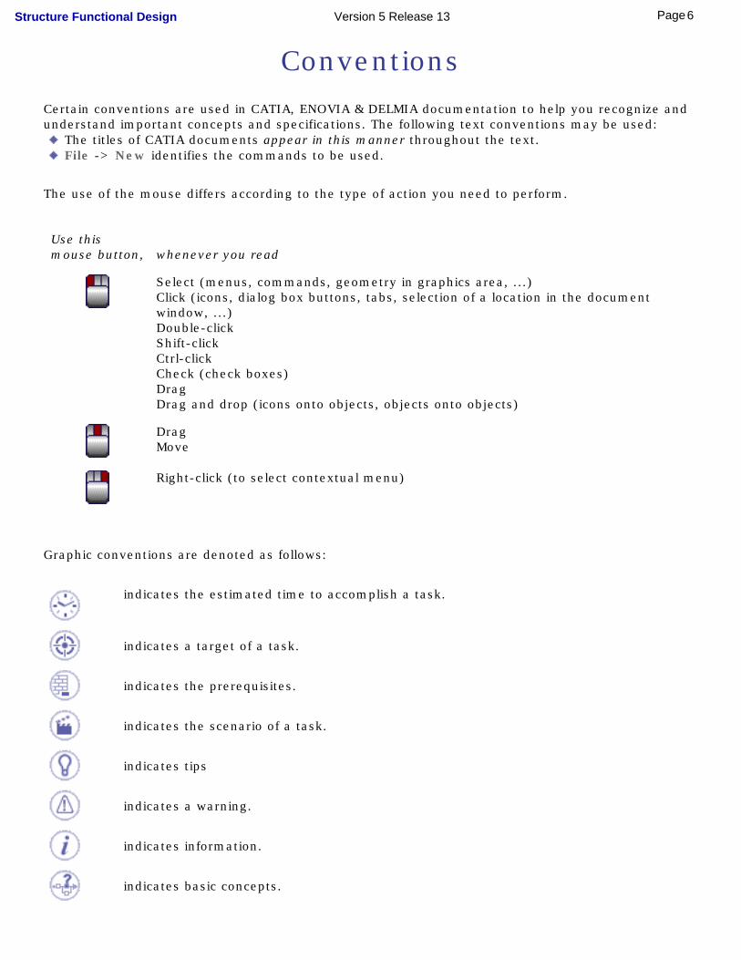
The use of the mouse differs according to the type of action you need to perform.
Use thismouse button, whenever you read
Select (menus, commands, geometry in graphics area, ...)Click (icons, dialog box buttons, tabs, selection of a location in the document window, ...)Double-clickShift-clickCtrl-clickCheck (check boxes)DragDrag and drop (icons onto objects, objects onto objects)
DragMove
Right-click (to select contextual menu)
Graphic conventions are denoted as follows:
indicates the estimated time to accomplish a task.
indicates a target of a task.
indicates the prerequisites.
indicates the scenario of a task.
indicates tips
indicates a warning.
indicates information.
indicates basic concepts.
6Page Structure Functional Design Version 5 Release 13

indicates methodological information.
indicates reference information.
indicates information regarding settings, customization, etc.
indicates the end of a task.
indicates functionalities that are new or enhanced with this Release.Enhancements can also be identified by a blue-colored background in the left-hand margin or on the text itself.
indicates functionalities that are P1-specific.
indicates functionalities that are P2-specific.
indicates functionalities that are P3-specific.
allows you to switch back the full-window viewing mode.
These icons in the table of contents correspond to the entries or mode.
"Site Map".
"Split View" mode.
"What's New".
"Preface".
"Getting Started".
"Basic Tasks".
"User Tasks" or the "Advanced Tasks".
"Workbench Description".
"Customizing".
"Reference".
"Methodology".
7Page Structure Functional Design Version 5 Release 13

"Glossary".
"Index".
8Page Structure Functional Design Version 5 Release 13
What's New?
Enhanced Functionalities
Optimal CATIA PLM Usabiity for Structure Functional DesignUser now warned whether or not data created in CATIA V5 can be correctly saved in ENOVIA LCA
Producing drawingsMore generative view style parameters are now available
9Page Structure Functional Design Version 5 Release 13
Getting StartedThis tutorial will guide you step-by-step through your first Structure Functional Design session, allowing you to get acquainted with the product.
You will need a Version 5 session and should be familiar with basic concepts such as document windows, standard and view toolbars.
You should be able to complete this tutorial in about 30 minutes.
Setting Up Your SessionCreating a Panel System
Creating an OpeningCreating a Plate System
Creating a Stiffener SystemMaking Design Changes
10Page Structure Functional Design Version 5 Release 13
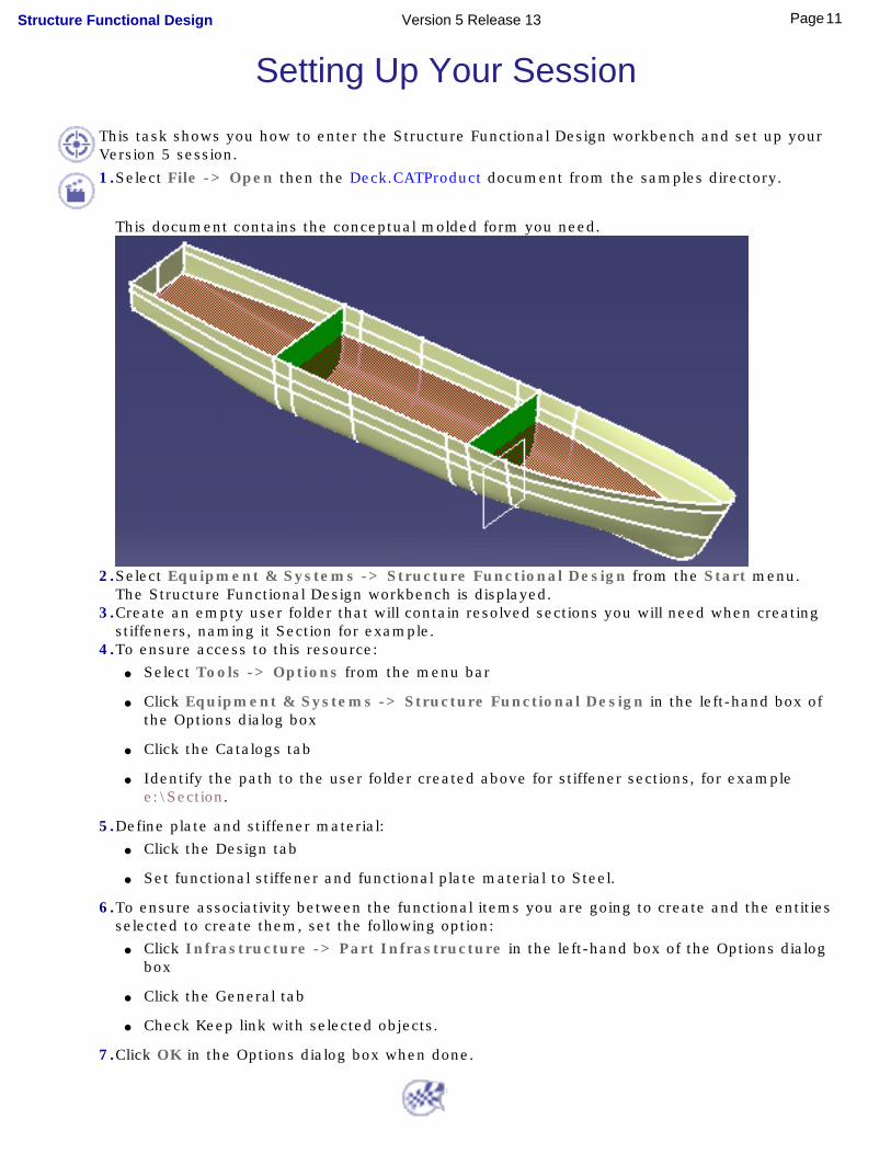
Setting Up Your SessionThis task shows you how to enter the Structure Functional Design workbench and set up your Version 5 session.
1.Select File -> Open then the Deck.CATProduct document from the samples directory.
This document contains the conceptual molded form you need.
2.Select Equipment & Systems -> Structure Functional Design from the Start menu.The Structure Functional Design workbench is displayed.
3.Create an empty user folder that will contain resolved sections you will need when creating stiffeners, naming it Section for example.
4.To ensure access to this resource: ● Select Tools -> Options from the menu bar
● Click Equipment & Systems -> Structure Functional Design in the left-hand box of the Options dialog box
● Click the Catalogs tab
● Identify the path to the user folder created above for stiffener sections, for example e:\Section.
5.Define plate and stiffener material: ● Click the Design tab
● Set functional stiffener and functional plate material to Steel.
6.To ensure associativity between the functional items you are going to create and the entities selected to create them, set the following option:
● Click Infrastructure -> Part Infrastructure in the left-hand box of the Options dialog box
● Click the General tab
● Check Keep link with selected objects.
7.Click OK in the Options dialog box when done.
11Page Structure Functional Design Version 5 Release 13

Creating a Panel SystemThis task shows you how to create the top level feature you will need, the panel system.
You will be working on the deck throughout this scenario.1.Click the Panel System icon.
The Panel System dialog box appears.
2.Define the class: ● Click Change... opposite Object class.
The Class Browser opens.
● Click the Expand tree icon to expand the class tree and view available object classes.
12Page Structure Functional Design Version 5 Release 13
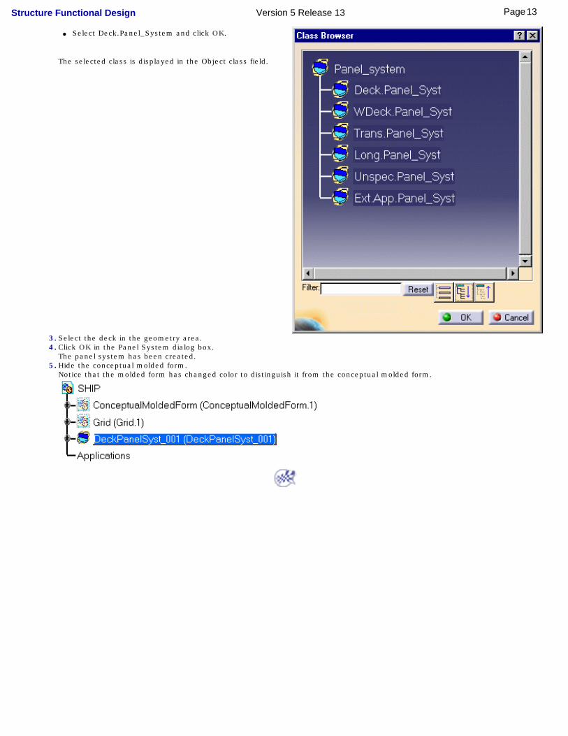
● Select Deck.Panel_System and click OK.
The selected class is displayed in the Object class field.
3.Select the deck in the geometry area.4.Click OK in the Panel System dialog box.
The panel system has been created.5.Hide the conceptual molded form.
Notice that the molded form has changed color to distinguish it from the conceptual molded form.
13Page Structure Functional Design Version 5 Release 13
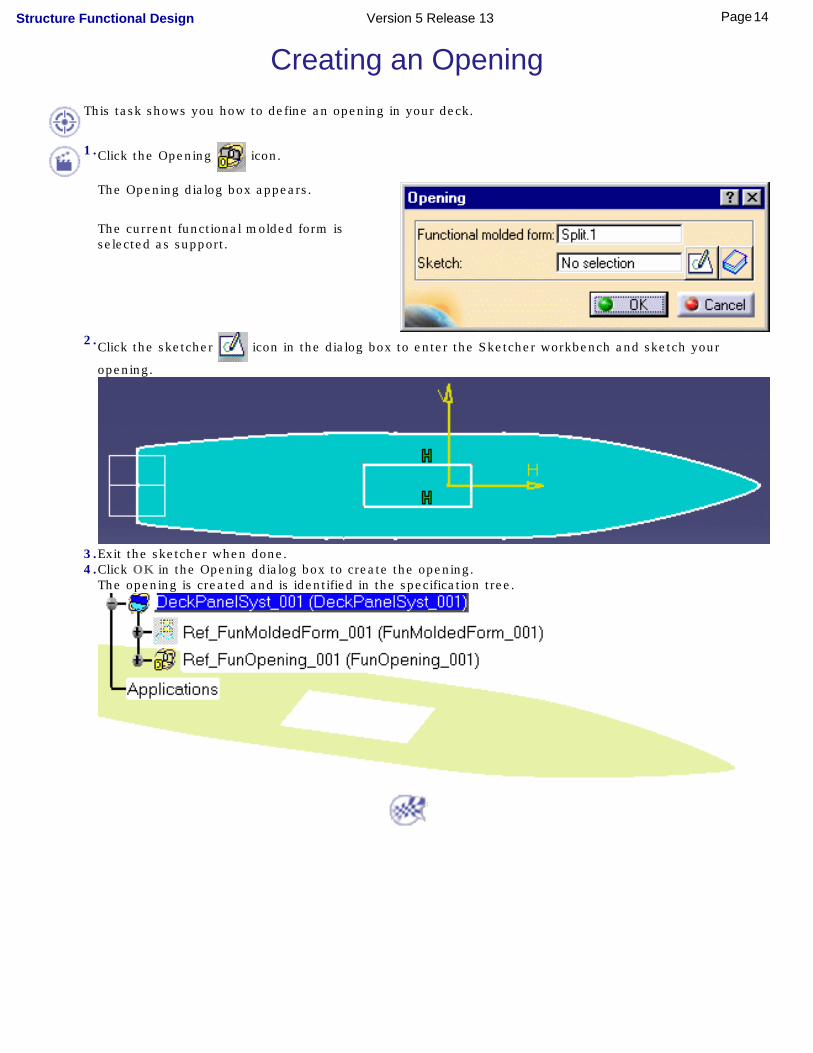
Creating an OpeningThis task shows you how to define an opening in your deck.
1.Click the Opening icon.
The Opening dialog box appears.
The current functional molded form is selected as support.
2.Click the sketcher icon in the dialog box to enter the Sketcher workbench and sketch your
opening.
3.Exit the sketcher when done.4.Click OK in the Opening dialog box to create the opening.
The opening is created and is identified in the specification tree.
14Page Structure Functional Design Version 5 Release 13

Creating a Plate SystemThis task shows you how to create a plate system which involves.
● Adding a plate system feature
● Dividing up the functional molded form into individual surfaces (straking)
● Creating functional plates.
Adding a Plate System Feature1. Click the Plate System icon.
The Plate System dialog box appears.
The current panel system is automatically selected.
A vector in the geometry area shows the direction of extrusion of any plates you create.
2. Define the class: ● Click Change... opposite Object class.
● Expand the object class tree.
● Select Deck.Plate_System in the Class Browser, then click OK.
3. Click the vector to change the direction of extrusion and have plates extruded upwards.4. Click OK.
The plate system feature is created.
15Page Structure Functional Design Version 5 Release 13
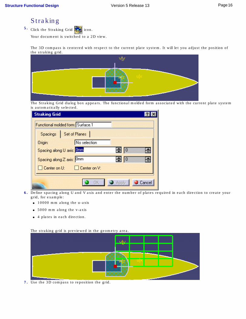
Straking5. Click the Straking Grid icon.
Your document is switched to a 2D view.
The 3D compass is centered with respect to the current plate system. It will let you adjust the position of the straking grid.
The Straking Grid dialog box appears. The functional molded form associated with the current plate system is automatically selected.
6. Define spacing along U and V axis and enter the number of plates required in each direction to create your grid, for example:
● 10000 mm along the u-axis
● 5000 mm along the v-axis
● 4 plates in each direction.
The straking grid is previewed in the geometry area.
7. Use the 3D compass to reposition the grid.
16Page Structure Functional Design Version 5 Release 13
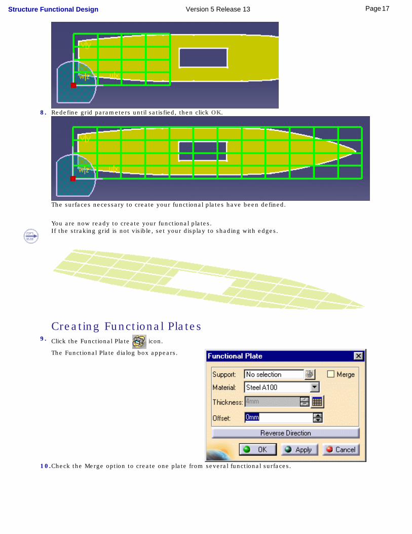
8. Redefine grid parameters until satisfied, then click OK.
The surfaces necessary to create your functional plates have been defined.
You are now ready to create your functional plates.If the straking grid is not visible, set your display to shading with edges.
Creating Functional Plates9. Click the Functional Plate icon.
The Functional Plate dialog box appears.
10.Check the Merge option to create one plate from several functional surfaces.
17Page Structure Functional Design Version 5 Release 13
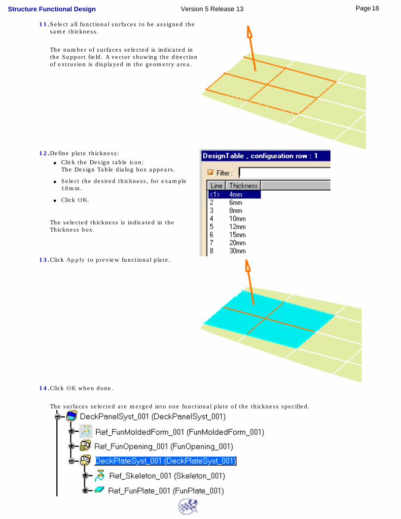
11.Select all functional surfaces to be assigned the same thickness.
The number of surfaces selected is indicated in the Support field. A vector showing the direction of extrusion is displayed in the geometry area.
12.Define plate thickness: ● Click the Design table icon:
The Design Table dialog box appears.
● Select the desired thickness, for example 10mm.
● Click OK.
The selected thickness is indicated in the Thickness box.
13.Click Apply to preview functional plate.
14.Click OK when done.
The surfaces selected are merged into one functional plate of the thickness specified.
18Page Structure Functional Design Version 5 Release 13
Creating a Stiffener SystemThis task shows you how to stiffen your deck which involves:
● Adding a stiffener system feature
● Creating stiffeners.
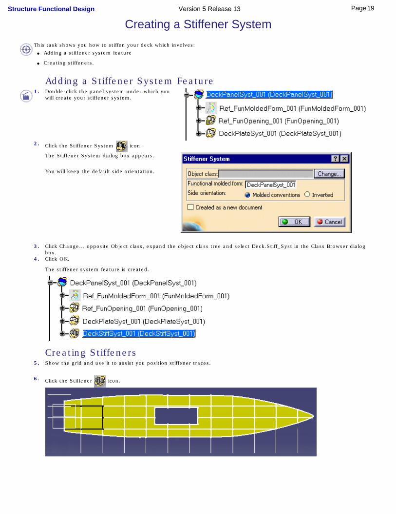
Adding a Stiffener System Feature1. Double-click the panel system under which you
will create your stiffener system.
2. Click the Stiffener System icon.
The Stiffener System dialog box appears.
You will keep the default side orientation.
3. Click Change... opposite Object class, expand the object class tree and select Deck.Stiff_Syst in the Class Browser dialog box.
4. Click OK.
The stiffener system feature is created.
Creating Stiffeners5. Show the grid and use it to assist you position stiffener traces.
6. Click the Stiffener icon.
19Page Structure Functional Design Version 5 Release 13

The Stiffener dialog box appears.
7. Load the standard section, WT 18x164, that you will need: ● In the Section list, select Other section...
The Catalog Browser dialog box opens letting you browse the content of the current catalog.
● Browse the list of families and double-click the Tees (WT) family.
● Browse the list of shapes and select section 18x164.
● Click OK.
The Section list in the Stiffener System dialog box is updated.
8. Keep default options defining material and orientation but set the anchor point to Top center.
9. Define trace curves along which the stiffener section will be swept:
● Click the sketcher icon in the dialog box.
The Sketcher workbench is opened and your functional molded form positioned in the H,V axis system. Plate traces are visible.
20Page Structure Functional Design Version 5 Release 13

● Sketch trace curves.
● Exit the sketcher.
Trace curves are visible on the functional molded form and the sketch is identified in the dialog box.
10. Click Apply in the Stiffener System box.
Note: The opening is taken into account.
11. Click OK when done.
21Page Structure Functional Design Version 5 Release 13
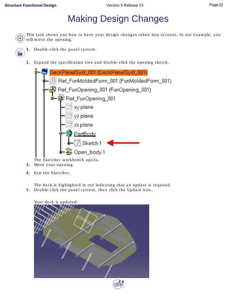
Making Design ChangesThis task shows you how to have your design changes taken into account. In our example, you will move the opening.
1. Double-click the panel system.
2. Expand the specification tree and double-click the opening sketch.
The Sketcher workbench opens.3. Move your opening.
4. Exit the Sketcher.
The deck is highlighted in red indicating that an update is required.5. Double-click the panel system, then click the Update icon.
Your deck is updated.
22Page Structure Functional Design Version 5 Release 13

User TasksThe tasks you will perform in the Structure Functional Design workbench involve creating panel systems composed of plate and stiffener systems, defining openings, and using shell expansion tools. You can also create plane systems, generate reports listing values of selected properties and produce drawings.
More advanced tasks cover managing your project, knowledgeware capabilities and working with ENOVIA LCA. A number of tasks illustrate interoperability with other CATIA V5 products.
Creating Panel SystemsCreating Plate Systems
Creating Stiffener SystemsCreating Openings
Editing Plates, Stiffeners & OpeningsShell Tools
Exporting Wireframe SkeletonsSplitting Plates & ShapesMerging Plates & ShapesCreating Plane Systems
Creating ReportsProducing Drawings
Managing User SectionsMirroring Systems Using Assembly Design Tool
Managing Your ProjectKnowledgeware CapabilitiesIntegration with ENOVIA LCA
Associativity
To ensure associativity between the functional items you create and entities selected to create them, you must check the Keep link with selected object option. This option is set in the Options dialog box (Tools -> Options..., Infrastructure -> Part Infrastructure).
Note: In the case of insert plates and openings, this option is automatically set.
Settings
Before you begin, ensure your structure functional design options have been set correctly.
23Page Structure Functional Design Version 5 Release 13

Creating Panel Systems
Create a panel system: define the class and select the conceptual surface
Create panel subsystems: define the class and select the functional molded form
Synchronize panel systems: in the specification tree, right-click a panel system and select Synchronize from the contextual menu
24Page Structure Functional Design Version 5 Release 13
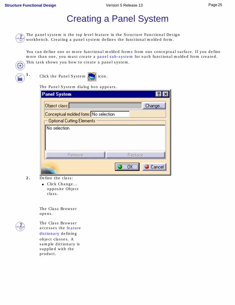
Creating a Panel SystemThe panel system is the top level feature in the Structure Functional Design workbench. Creating a panel system defines the functional molded form.
You can define one or more functional molded forms from one conceptual surface. If you define more than one, you must create a panel sub-system for each functional molded form created. This task shows you how to create a panel system.
1. Click the Panel System icon.
The Panel System dialog box appears.
2. Define the class: ● Click Change...
opposite Object class.
The Class Browser opens.
The Class Browser accesses the feature dictionary defining object classes. A sample dictionary is supplied with the product.
25Page Structure Functional Design Version 5 Release 13
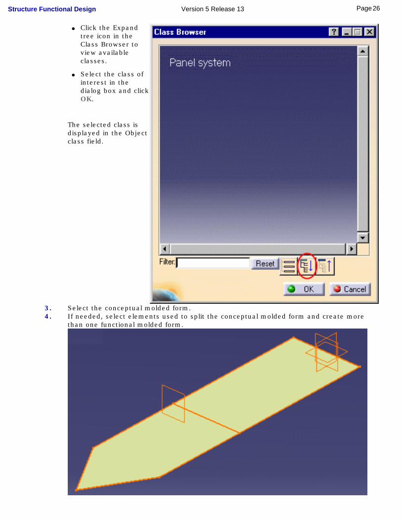
● Click the Expand tree icon in the Class Browser to view available classes.
● Select the class of interest in the dialog box and click OK.
The selected class is displayed in the Object class field.
3. Select the conceptual molded form.4. If needed, select elements used to split the conceptual molded form and create more
than one functional molded form.
26Page Structure Functional Design Version 5 Release 13
In our example, the conceptual molded form is split using a cutting plane into two functional molded forms.
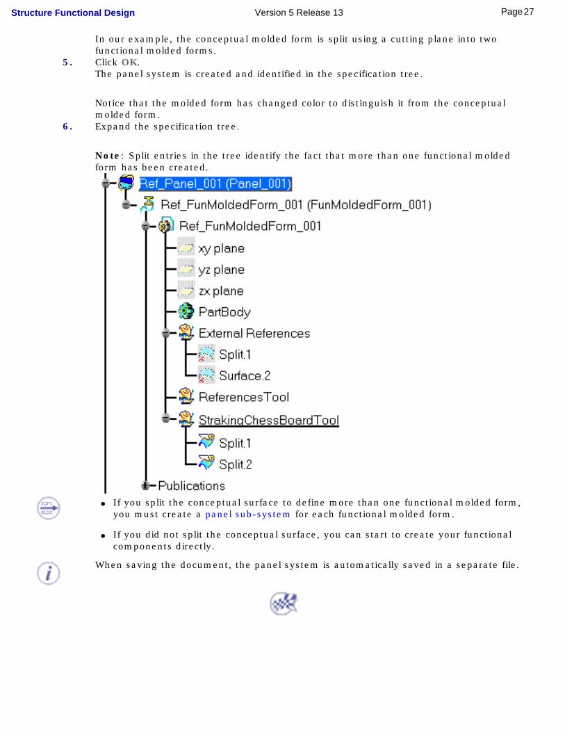
5. Click OK.The panel system is created and identified in the specification tree.
Notice that the molded form has changed color to distinguish it from the conceptual molded form.
6. Expand the specification tree.
Note: Split entries in the tree identify the fact that more than one functional molded form has been created.
● If you split the conceptual surface to define more than one functional molded form, you must create a panel sub-system for each functional molded form.
● If you did not split the conceptual surface, you can start to create your functional components directly.
When saving the document, the panel system is automatically saved in a separate file.
27Page Structure Functional Design Version 5 Release 13
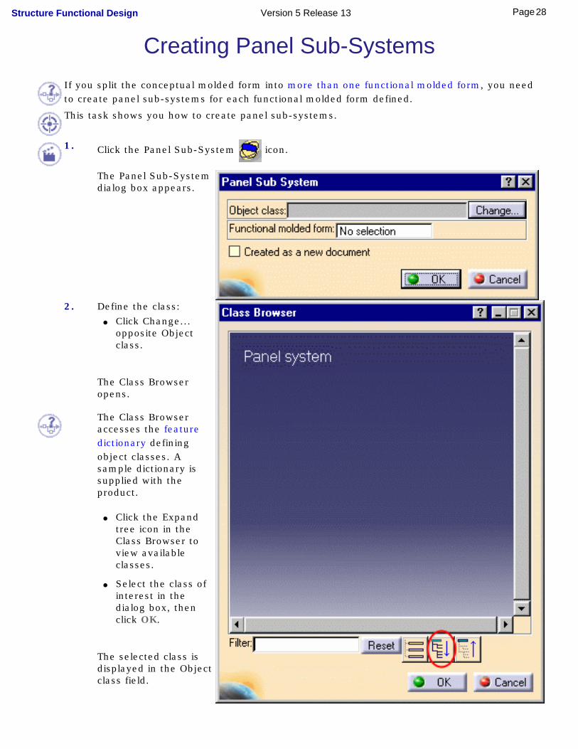
Creating Panel Sub-SystemsIf you split the conceptual molded form into more than one functional molded form, you need to create panel sub-systems for each functional molded form defined.
This task shows you how to create panel sub-systems.
1. Click the Panel Sub-System icon.
The Panel Sub-System dialog box appears.
2. Define the class: ● Click Change...
opposite Object class.
The Class Browser opens.
The Class Browser accesses the feature dictionary defining object classes. A sample dictionary is supplied with the product.
● Click the Expand tree icon in the Class Browser to view available classes.
● Select the class of interest in the dialog box, then click OK.
The selected class is displayed in the Object class field.
28Page Structure Functional Design Version 5 Release 13

3. Select the corresponding functional molded form.4. To save the panel sub-system in a separate file, check the Created as a new document
option.
The panel sub-system will be saved separately in the same directory as the document.
Unchecked, the panel sub-system is saved in the original document.5. Click OK.
The first panel sub-system is created.
You can, if desired, create openings at this stage.
6. Activate the panel system.7. Repeat to create as many panel sub-systems as functional molded forms.
29Page Structure Functional Design Version 5 Release 13

Synchronizing Panel Systems To support the Work package mode when saving documents in ENOVIA LCA, contextual links have been replaced by a Copy then Paste Special..., AsResultWithLink option as of Version 5 Release 12.
Since Copy-Paste Special..., AsResultWithLink does not support publication, you need to manually synchronize your panel systems with the underlying conceptual molded form if the molded form has been replaced.
ENOVIA LCA informs you about panel systems needing synchronized.This task shows you how to synchronize panel systems with underlying conceptual molded forms. It assumes that after you created your panel system, you made changes to the conceptual molded form.
1. Add an opening to your molded form.
30Page Structure Functional Design Version 5 Release 13
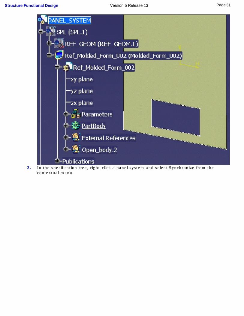
2. In the specification tree, right-click a panel system and select Synchronize from the contextual menu.
31Page Structure Functional Design Version 5 Release 13
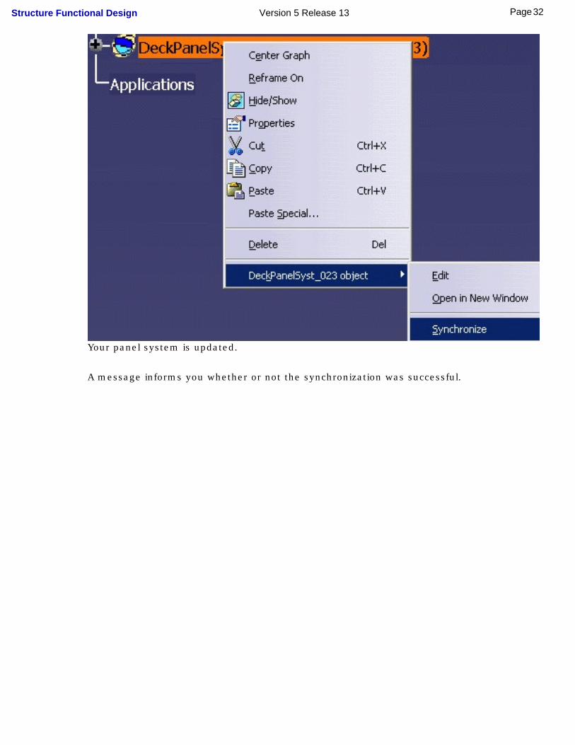
Your panel system is updated.
A message informs you whether or not the synchronization was successful.
32Page Structure Functional Design Version 5 Release 13

3. Save your document.
33Page Structure Functional Design Version 5 Release 13
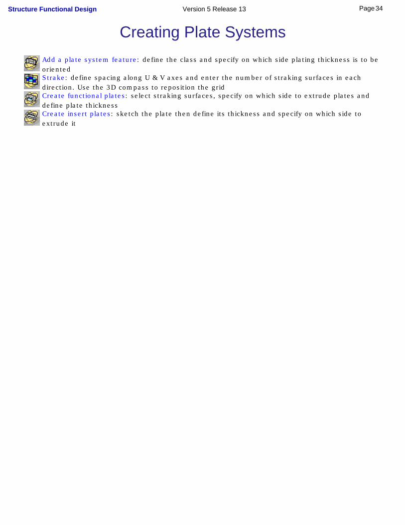
Creating Plate Systems
Add a plate system feature: define the class and specify on which side plating thickness is to be orientedStrake: define spacing along U & V axes and enter the number of straking surfaces in each direction. Use the 3D compass to reposition the gridCreate functional plates: select straking surfaces, specify on which side to extrude plates and define plate thicknessCreate insert plates: sketch the plate then define its thickness and specify on which side to extrude it
34Page Structure Functional Design Version 5 Release 13

Adding a Plate System FeatureThis task shows you how to create a plate system feature.
Already defined a panel system.
1.Click the Plate System icon.
The Plate System dialog box appears.
The current panel system is automatically selected.
2.Define the class: ● Click Change...
opposite Object class.
The Class Browser opens and accesses the feature dictionary defining object classes. A sample dictionary is supplied with the product.
● If necessary, expand the object class tree and select the desired class.
● Click OK.
The selected class is displayed in the Object class field of the Plate System dialog box.
35Page Structure Functional Design Version 5 Release 13

3.Specify the direction in which plating thickness is to be oriented.By default, the orientation of plating thickness is defined according to molded conventions. Molded conventions are project resources.
A vector in the geometry area shows the orientation for all plates you will create in this plate system.
36Page Structure Functional Design Version 5 Release 13
To invert the direction: ● Click the appropriate option in the dialog box,
Or,
● Click the vector in the geometry area.
4.Check Created as a new document if you want to save the plate system in a separate file.The plate system will be saved separately in the same directory as the original document.
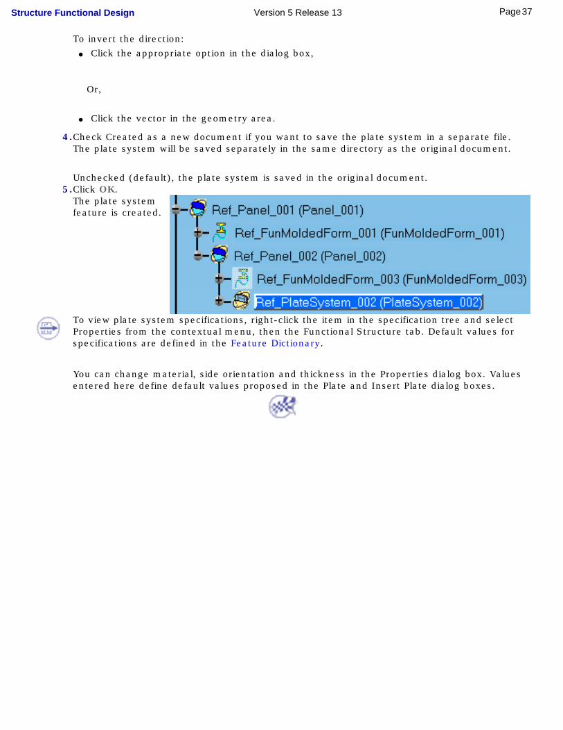
Unchecked (default), the plate system is saved in the original document.5.Click OK.
The plate system feature is created.
To view plate system specifications, right-click the item in the specification tree and select Properties from the contextual menu, then the Functional Structure tab. Default values for specifications are defined in the Feature Dictionary.
You can change material, side orientation and thickness in the Properties dialog box. Values entered here define default values proposed in the Plate and Insert Plate dialog boxes.
37Page Structure Functional Design Version 5 Release 13
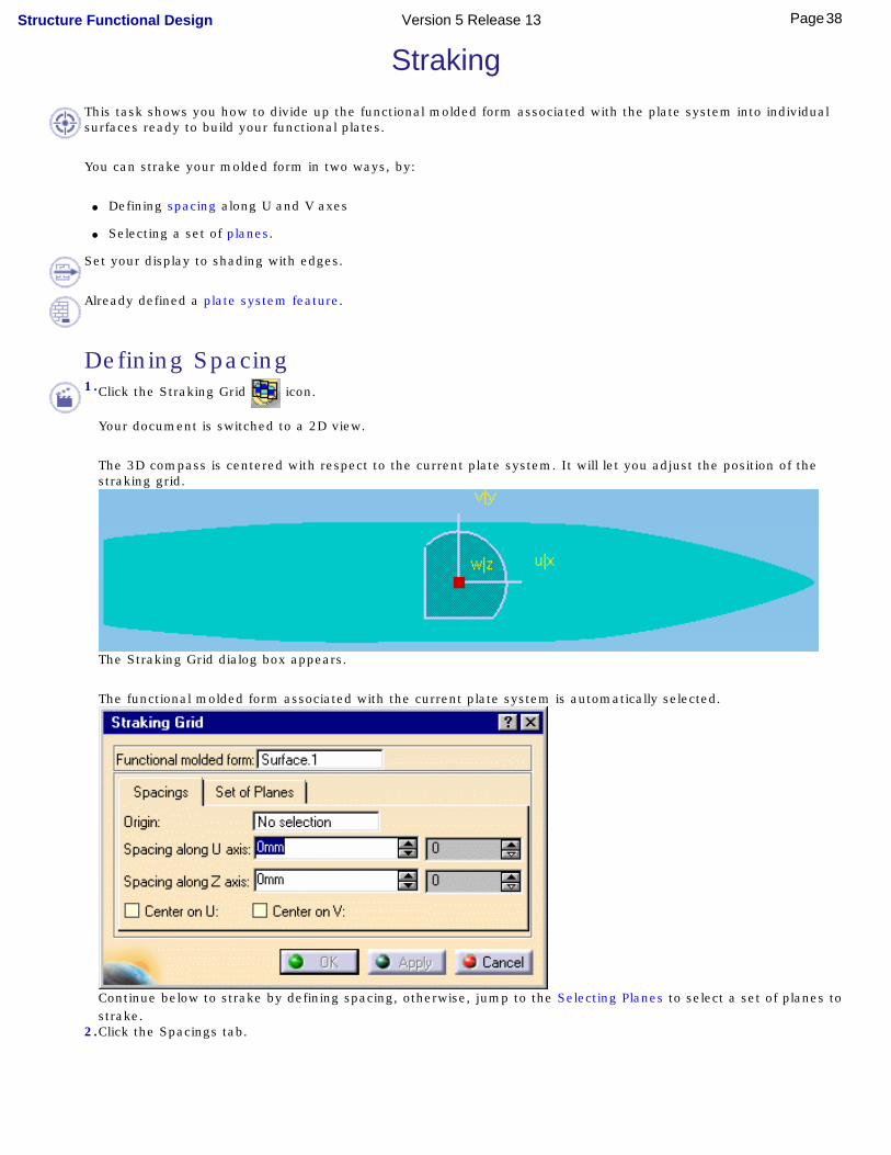
StrakingThis task shows you how to divide up the functional molded form associated with the plate system into individual surfaces ready to build your functional plates.
You can strake your molded form in two ways, by:
● Defining spacing along U and V axes
● Selecting a set of planes.
Set your display to shading with edges.
Already defined a plate system feature.
Defining Spacing1.Click the Straking Grid icon.
Your document is switched to a 2D view.
The 3D compass is centered with respect to the current plate system. It will let you adjust the position of the straking grid.
The Straking Grid dialog box appears.
The functional molded form associated with the current plate system is automatically selected.
Continue below to strake by defining spacing, otherwise, jump to the Selecting Planes to select a set of planes to strake.
2.Click the Spacings tab.
38Page Structure Functional Design Version 5 Release 13

3.Define spacing along U and V axes and enter the number of straking surfaces required in each direction to create your grid.
The straking grid is previewed in the geometry area.
4.Position the grid as desired: ● Use the 3D compass to reposition the grid.
● Select a point to locate the 3D compass on the selected point (Origin field).
● Check Center on U option to center the grid along the U- axis.
● Check Center on V option to center the grid along the V-axis.
39Page Structure Functional Design Version 5 Release 13
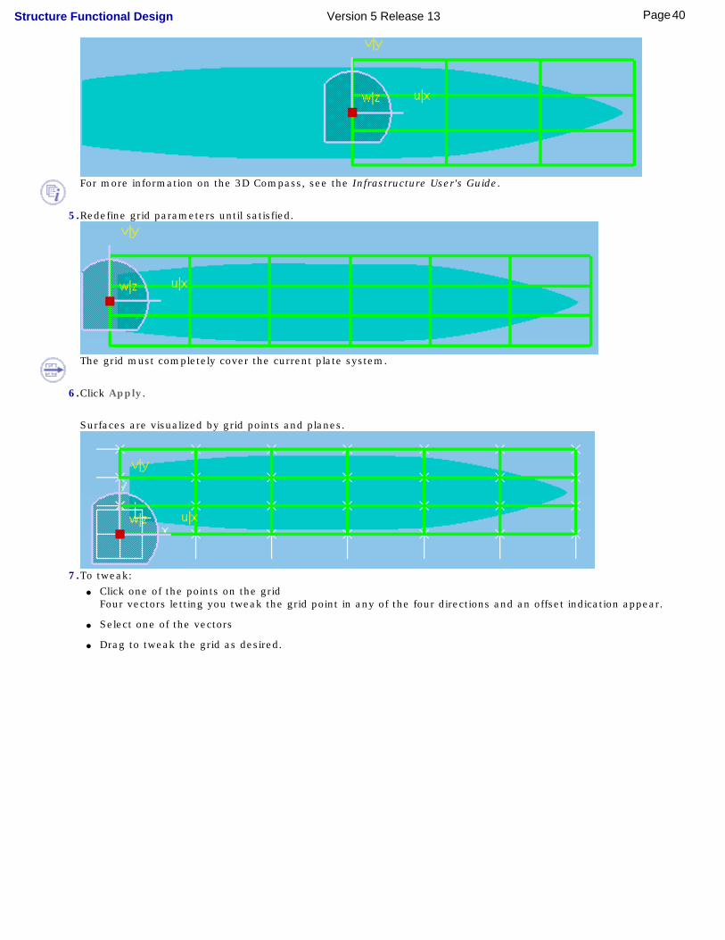
For more information on the 3D Compass, see the Infrastructure User's Guide.
5.Redefine grid parameters until satisfied.
The grid must completely cover the current plate system.
6.Click Apply.
Surfaces are visualized by grid points and planes.
7.To tweak: ● Click one of the points on the grid
Four vectors letting you tweak the grid point in any of the four directions and an offset indication appear.
● Select one of the vectors
● Drag to tweak the grid as desired.
40Page Structure Functional Design Version 5 Release 13
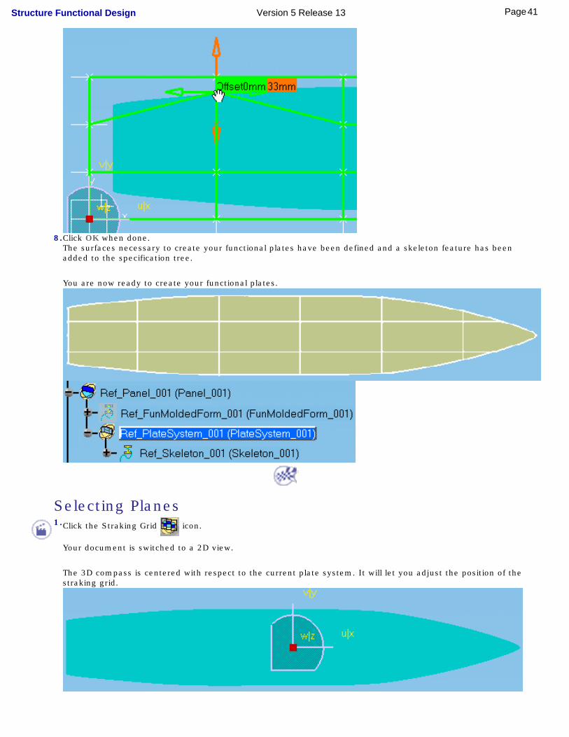
8.Click OK when done.The surfaces necessary to create your functional plates have been defined and a skeleton feature has been added to the specification tree.
You are now ready to create your functional plates.
Selecting Planes1.Click the Straking Grid icon.
Your document is switched to a 2D view.
The 3D compass is centered with respect to the current plate system. It will let you adjust the position of the straking grid.
41Page Structure Functional Design Version 5 Release 13
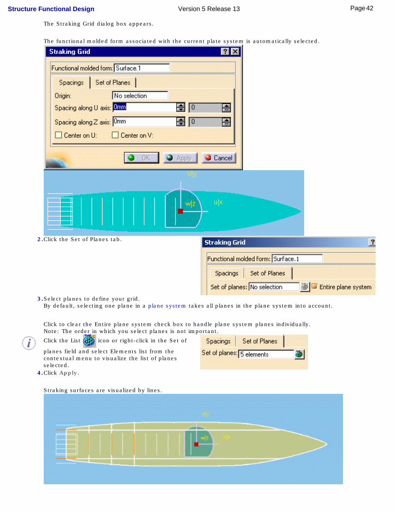
The Straking Grid dialog box appears.
The functional molded form associated with the current plate system is automatically selected.
2.Click the Set of Planes tab.
3.Select planes to define your grid. By default, selecting one plane in a plane system takes all planes in the plane system into account.
Click to clear the Entire plane system check box to handle plane system planes individually. Note: The order in which you select planes is not important.
Click the List icon or right-click in the Set of
planes field and select Elements list from the contextual menu to visualize the list of planes selected.
4.Click Apply.
Straking surfaces are visualized by lines.
42Page Structure Functional Design Version 5 Release 13

5.Click OK when done.
The surfaces necessary to create your functional plates have been defined and a skeleton feature has been added to the specification tree.
You are now ready to create your functional plates.
● To modify the straking grid and for example move a plane, you must first place the grid tool in the Show space. To do so, right-click the plate system and select Hide/Show Grid from the contextual menu.
● To remove the straking grid, right-click the plate system and select Remove Grid from the contextual menu.
43Page Structure Functional Design Version 5 Release 13
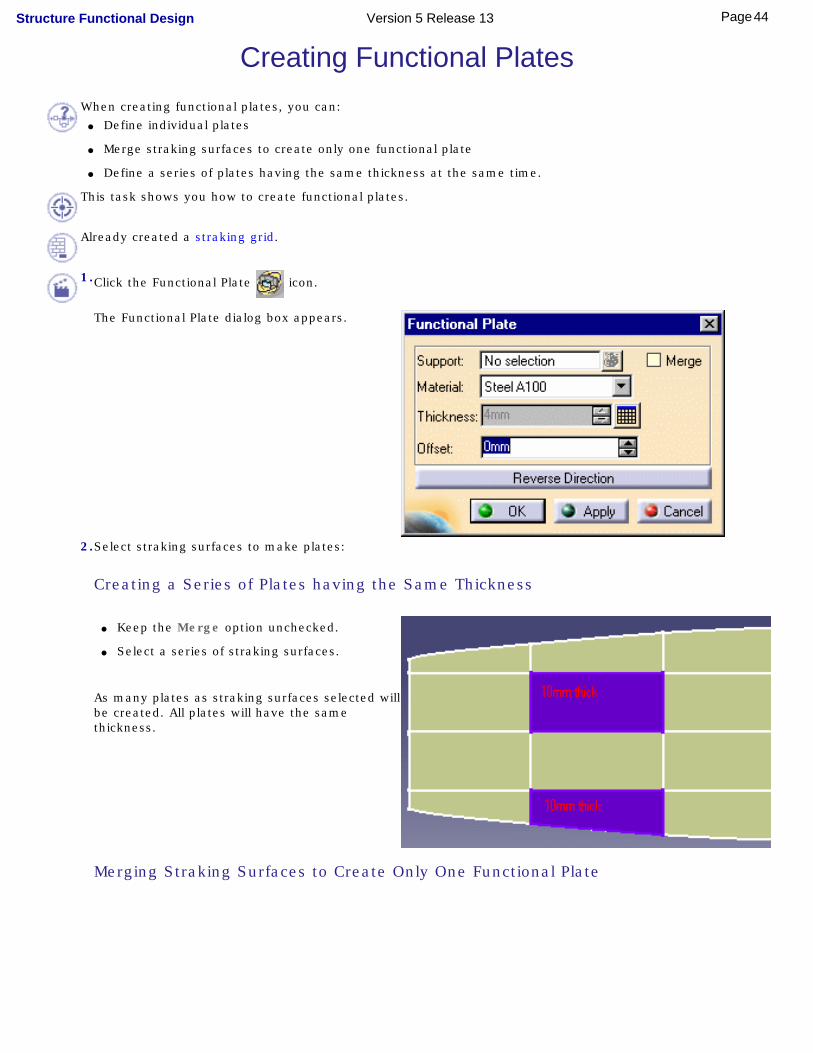
Creating Functional PlatesWhen creating functional plates, you can:
● Define individual plates
● Merge straking surfaces to create only one functional plate
● Define a series of plates having the same thickness at the same time.
This task shows you how to create functional plates.
Already created a straking grid.
1.Click the Functional Plate icon.
The Functional Plate dialog box appears.
2.Select straking surfaces to make plates:
Creating a Series of Plates having the Same Thickness
● Keep the Merge option unchecked.
● Select a series of straking surfaces.
As many plates as straking surfaces selected will be created. All plates will have the same thickness.
Merging Straking Surfaces to Create Only One Functional Plate
44Page Structure Functional Design Version 5 Release 13
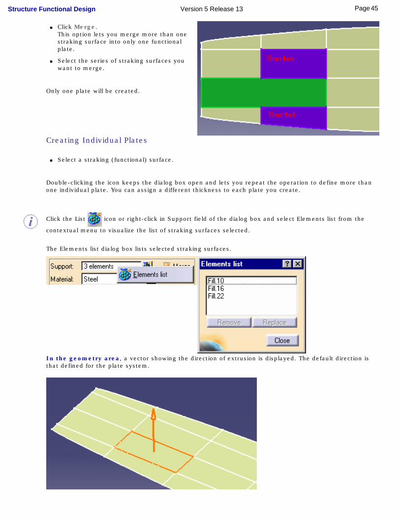
● Click Merge.This option lets you merge more than one straking surface into only one functional plate.
● Select the series of straking surfaces you want to merge.
Only one plate will be created.
Creating Individual Plates
● Select a straking (functional) surface.
Double-clicking the icon keeps the dialog box open and lets you repeat the operation to define more than one individual plate. You can assign a different thickness to each plate you create.
Click the List icon or right-click in Support field of the dialog box and select Elements list from the
contextual menu to visualize the list of straking surfaces selected.
The Elements list dialog box lists selected straking surfaces.
In the geometry area, a vector showing the direction of extrusion is displayed. The default direction is that defined for the plate system.
45Page Structure Functional Design Version 5 Release 13

3.If necessary, click the vector or click Reverse Direction in the dialog box to extrude the plate in the direction opposite that shown in the preview.
The orientation proposed is that set for the plate system.
4.If necessary, select a different material-grade combination in the Material drop-down list.
The material proposed is the default material specified for the plate system in the Feature dictionary, or if none is defined here, that set in the settings.
5.Define plate thickness:. ● Click the Design table icon:
The Design Table dialog box appears.
● Select the desired thickness, then click OK.
The thickness proposed is the default thickness specified for the plate system in the Feature dictionary, or if none is defined here, it is taken from the thickness table.
6.Click Apply to preview functional plate.
7.Make any adjustments necessary, then click Apply again.
8.Click OK when done.
46Page Structure Functional Design Version 5 Release 13

You can customize plate color using the Tools -> Options command ( Equipment & Systems -> Structure Functional Design, Design tab).
47Page Structure Functional Design Version 5 Release 13
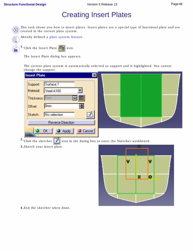
Creating Insert PlatesThis task shows you how to insert plates. Insert plates are a special type of functional plate and are created in the current plate system.
Already defined a plate system feature.
1.Click the Insert Plate icon.
The Insert Plate dialog box appears.
The current plate system is automatically selected as support and is highlighted. You cannot change the support.
2.Click the sketcher icon in the dialog box to enter the Sketcher workbench.
3.Sketch your insert plate.
4.Exit the sketcher when done.
48Page Structure Functional Design Version 5 Release 13
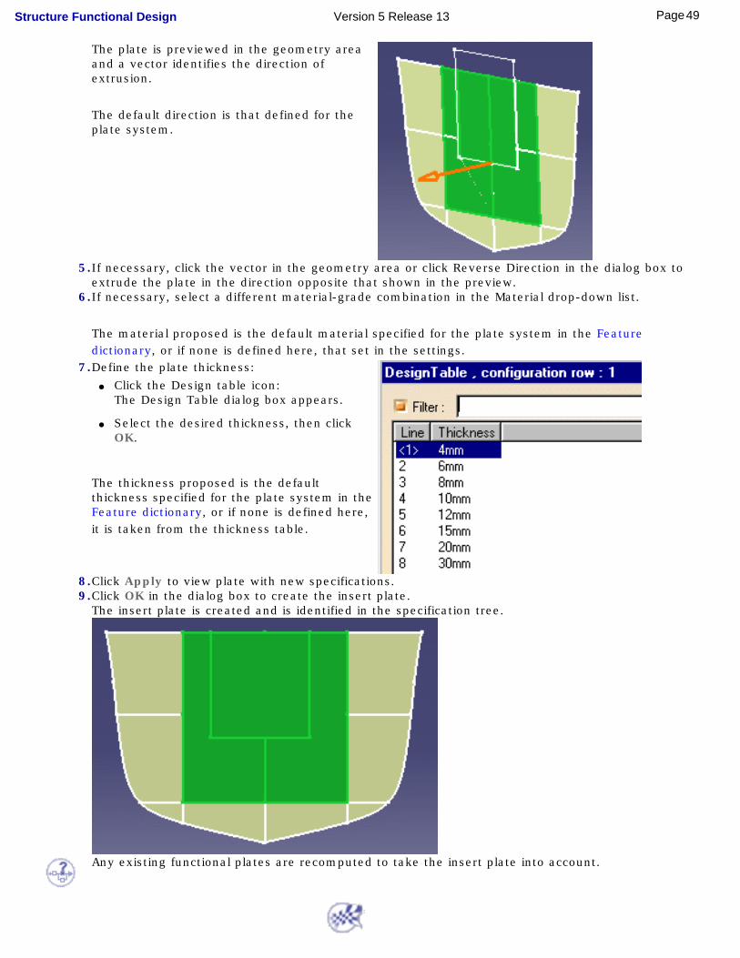
The plate is previewed in the geometry area and a vector identifies the direction of extrusion.
The default direction is that defined for the plate system.
5.If necessary, click the vector in the geometry area or click Reverse Direction in the dialog box to extrude the plate in the direction opposite that shown in the preview.
6.If necessary, select a different material-grade combination in the Material drop-down list.
The material proposed is the default material specified for the plate system in the Feature dictionary, or if none is defined here, that set in the settings.
7.Define the plate thickness: ● Click the Design table icon:
The Design Table dialog box appears.
● Select the desired thickness, then click OK.
The thickness proposed is the default thickness specified for the plate system in the Feature dictionary, or if none is defined here, it is taken from the thickness table.
8.Click Apply to view plate with new specifications.9.Click OK in the dialog box to create the insert plate.
The insert plate is created and is identified in the specification tree.
Any existing functional plates are recomputed to take the insert plate into account.
49Page Structure Functional Design Version 5 Release 13

Creating Stiffener Systems
Make up a list of sections: double-click the Section icon and select sections you need from the Catalog browser.Add a stiffener system feature: define the class and specify on which side stiffeners are to be placedCreate stiffeners: set parameters in the Stiffener System dialog box then define stiffener trace curvesCreate twisted stiffeners: set parameters in the Twisted Profile dialog box then select trace curvesCreate pillars: set parameters in the Pillar dialog box, then select sets of longitudinal and cross planes as well as the lower deck
50Page Structure Functional Design Version 5 Release 13
Making Up a List of Sections
Sections used to create structures can be: ● Standard catalog sections
Samples of standard catalogs are supplied with the product. Sections in these catalogs are parametric sketches associated with design tables (CSV-type Excel files).
● User-defined sections.
Before you start working, make up a list of the catalog and/or user sections you will need. Sections are saved in a resolved folder defined in your settings. Catalog and user sections can then be accessed directly via the Section list of the appropriate dialog box.
This task shows how to make up a list of standard catalog and user sections suited to your needs.
No sample document is provided.
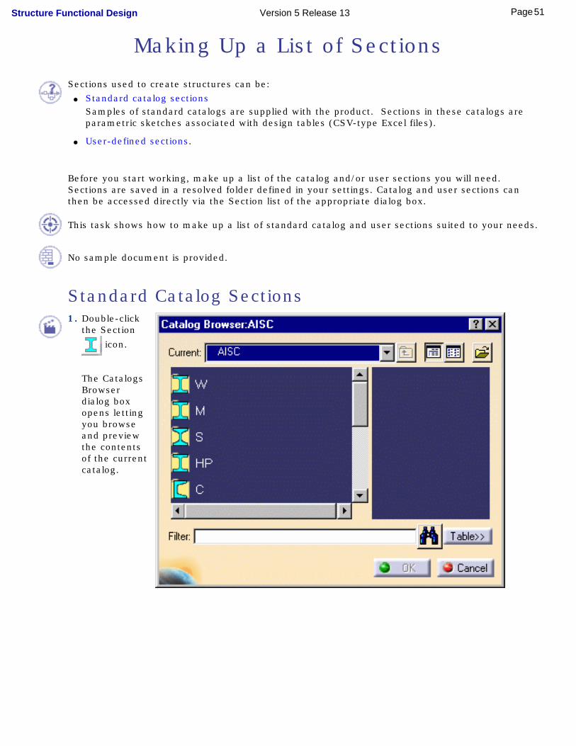
Standard Catalog Sections1. Double-click
the Section
icon.
The Catalogs Browser dialog box opens letting you browse and preview the contents of the current catalog.
51Page Structure Functional Design Version 5 Release 13

2. Click the Browse another
catalog icon to open the File Selection dialog box and choose another catalog.
3. Select the OTUA catalog for example and click Open.
4. Browse the list of families in the Catalog Browser dialog box and double-click the family of interest, for example IPE.
52Page Structure Functional Design Version 5 Release 13

5. Browse the list of shapes and select the section of interest, for example IPE200, then click OK in the dialog box.
For information on options in the Catalog Browser, see Using Catalogs in the Infrastructure User's Guide.
6. Repeat until you have selected all catalog sections you are likely to need.
Copies of the sections are added to the resolved folder defined in your settings (see the Customizing section of your guide).
In Structure Functional Design, the location of this folder can also be managed as a project resource.
The Other Section... option in the Section list of the appropriate dialog box also gives you access to the catalog browser.
User-defined Sections
User-defined sections are of two types:
● Parametric sections stored in a user catalog and accessed in the same way as standard catalog sections.
● Resolved sections saved directly in the resolved folder containing the list of sections.
Both types of section can be created using the Sketcher. For more information on sketcher capabilities, see the Sketcher User's Guide.
1. To make up a list of user sections:
Double-click the Section icon and proceed as above for standard catalog sections.
Or,
Save resolved sections directly in the resolved folder defined in your settings (see the Customizing section of your guide).
53Page Structure Functional Design Version 5 Release 13

Adding a Stiffener System FeatureThis task shows you how to create a stiffener system feature.
Already defined a panel system.
1. Click the Stiffener System icon.
The Stiffener System dialog box appears.
The stiffener system is created under the current panel system or sub-system.
2. Define the class: ● Click
Change... opposite Object class.
The Class Browser opens and accesses the feature dictionary defining object classes. A sample dictionary is supplied with the product.
● If necessary, expand the object class tree and select the desired class.
● Click OK.
The selected class is displayed in the Object class field of the Stiffener dialog box.
54Page Structure Functional Design Version 5 Release 13
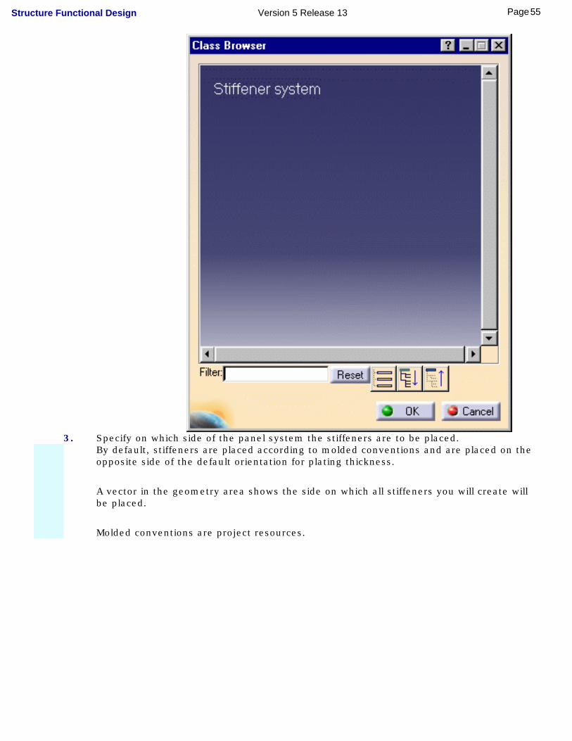
3. Specify on which side of the panel system the stiffeners are to be placed. By default, stiffeners are placed according to molded conventions and are placed on the
opposite side of the default orientation for plating thickness.
A vector in the geometry area shows the side on which all stiffeners you will create will be placed.
Molded conventions are project resources.
55Page Structure Functional Design Version 5 Release 13

To change sides: ● Click the appropriate option in the dialog box,
Or,
● Click the vector in the geometry area.
4. Check Created as a new document if you want to save the stiffener system in a separate file.The stiffener system will be saved separately in the same directory as the original document.
Unchecked (default), the stiffener system is saved in the original document.5. Click OK.
The stiffener system feature is added to the specification tree.
To view stiffener system specifications, right-click the item in the specification tree and select Properties from the contextual menu, then the Functional Structure tab. Default values for specifications are defined in the feature dictionary.
You can change material, side orientation and section in the Properties dialog box. Values entered here define default values proposed in the Stiffener System, Twisted Profile and Pillar dialog boxes.
56Page Structure Functional Design Version 5 Release 13

Creating StiffenersStiffeners are created on the current stiffener system. The selected stiffener section is swept along trace curves defined by reference planes and/or using the sketcher.
Stiffeners take into account any existing openings.This task shows you how to stiffen your functional molded forms.
Already defined a stiffener system feature.
1. Click the Stiffener icon.
The Stiffener System dialog box appears.
Stiffeners are created for the current stiffener system.
Do not forget to define directory in which available sections will be stored (Tools -> Options, Equipment & Systems -> Structure Functional Design, Catalogs tab).
2. In the Section list, select the shape you want to use. Click: ● One of the available section names, or
● Other section... to access catalog sections not already listed.
The first time you enter the workbench, you must initialize the section list with catalog and/or user sections.
You can also set a default section in the Feature dictionary that specifies the value proposed in the dialog box.
57Page Structure Functional Design Version 5 Release 13
3. If necessary, select a different material-grade combination in the Material drop-down list.
The material proposed is the default material specified for the stiffener system in the Feature dictionary, or if none is defined here, that set in the settings.
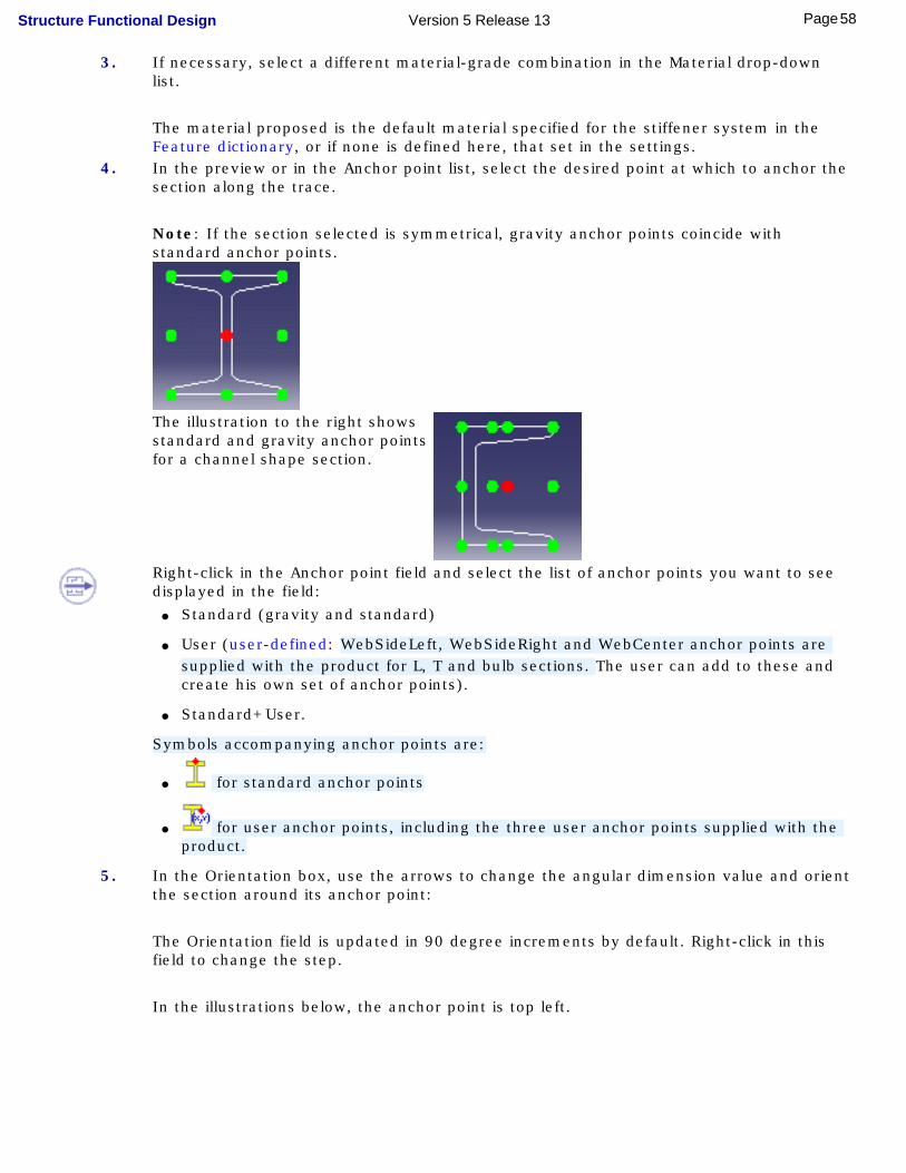
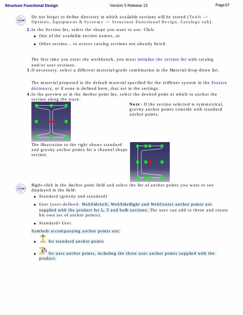
4. In the preview or in the Anchor point list, select the desired point at which to anchor the section along the trace.
Note: If the section selected is symmetrical, gravity anchor points coincide with standard anchor points.
The illustration to the right shows standard and gravity anchor points for a channel shape section.
Right-click in the Anchor point field and select the list of anchor points you want to see displayed in the field:
● Standard (gravity and standard)
● User (user-defined: WebSideLeft, WebSideRight and WebCenter anchor points are supplied with the product for L, T and bulb sections. The user can add to these and create his own set of anchor points).
● Standard+User.
Symbols accompanying anchor points are:
● for standard anchor points
● for user anchor points, including the three user anchor points supplied with the product.
5. In the Orientation box, use the arrows to change the angular dimension value and orient the section around its anchor point:
The Orientation field is updated in 90 degree increments by default. Right-click in this field to change the step.
In the illustrations below, the anchor point is top left.
58Page Structure Functional Design Version 5 Release 13
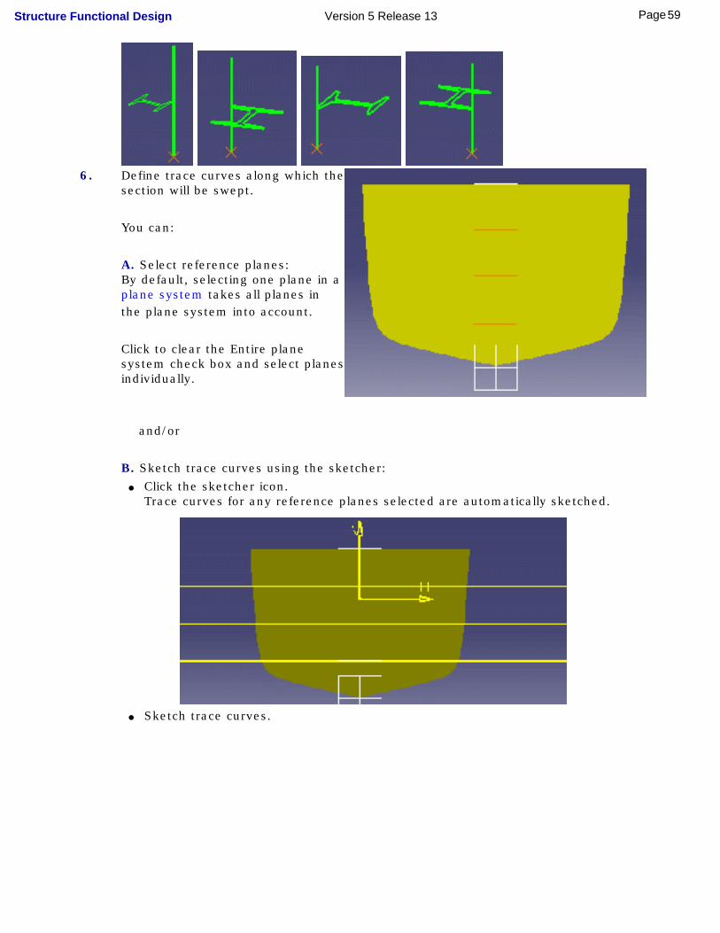
6. Define trace curves along which the
section will be swept.
You can:
A. Select reference planes: By default, selecting one plane in a
plane system takes all planes in the plane system into account.
Click to clear the Entire plane system check box and select planes individually.
and/or
B. Sketch trace curves using the sketcher: ● Click the sketcher icon.
Trace curves for any reference planes selected are automatically sketched.
● Sketch trace curves.
59Page Structure Functional Design Version 5 Release 13
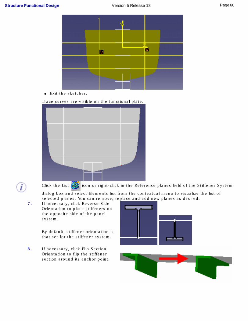
● Exit the sketcher.
Trace curves are visible on the functional plate.
Click the List icon or right-click in the Reference planes field of the Stiffener System
dialog box and select Elements list from the contextual menu to visualize the list of selected planes. You can remove, replace and add new planes as desired.
7. If necessary, click Reverse Side Orientation to place stiffeners on the opposite side of the panel system.
By default, stiffener orientation is that set for the stiffener system.
8. If necessary, click Flip Section
Orientation to flip the stiffener section around its anchor point.
60Page Structure Functional Design Version 5 Release 13

9. Click OK in the Stiffener System dialog box to create stiffeners.
61Page Structure Functional Design Version 5 Release 13
Creating Twisted StiffenersTwisted stiffeners are created on the current stiffener system. By default, they are defined normal to the functional molded form (reference surface).
The selected stiffener section is swept along trace curves (welded line) defined using shell expansion tools or using Generative Shape Design.
This task shows you how to stiffen your hull.
Already defined a stiffener system feature.
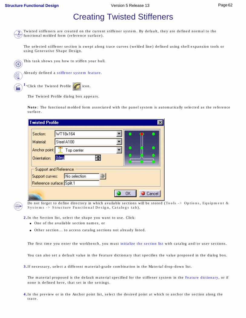
1.Click the Twisted Profile icon.
The Twisted Profile dialog box appears.
Note: The functional molded form associated with the panel system is automatically selected as the reference surface.
Do not forget to define directory in which available sections will be stored (Tools -> Options, Equipment & Systems -> Structure Functional Design, Catalogs tab).
2.In the Section list, select the shape you want to use. Click: ● One of the available section names, or
● Other section... to access catalog sections not already listed.
The first time you enter the workbench, you must initialize the section list with catalog and/or user sections.
You can also set a default value in the Feature dictionary that specifies the value proposed in the dialog box.
3.If necessary, select a different material-grade combination in the Material drop-down list.
The material proposed is the default material specified for the stiffener system in the Feature dictionary, or if none is defined here, that set in the settings.
4.In the preview or in the Anchor point list, select the desired point at which to anchor the section along the trace.
62Page Structure Functional Design Version 5 Release 13

Note: If the section selected is symmetrical, gravity anchor points coincide with standard anchor points.
The illustration to the right shows standard and gravity anchor points for a channel shape section.
Right-click in the Anchor point field and select the list of anchor points you want to see displayed in the field:
● Standard (gravity and standard)
● User (user-defined: WebSideLeft, WebSideRight and WebCenter anchor points are supplied with the product for L, T and bulb sections. The user can add to these and create his own set of anchor points).
● Standard+User.
Symbols accompanying anchor points are:
● for standard anchor points
● for user anchor points, including the three user anchor points supplied with the product.
5.Select the trace curve serving as support curve.
The support curve corresponds to the welded line and must lie on the reference surface. The twisted stiffener is routed along the selected support.
You can:● Define trace curves using:
● Shell Expansion tools, or
● the Generative Shape Design workbench (at intersections of planes and surfaces for example)
● Select a plane:
The trace curve is generated at the intersection of the plane and the reference surface.
A preview guides you as you create. Any changes in stiffener definition are immediately reflected in the preview.
63Page Structure Functional Design Version 5 Release 13

Right-click in the geometry area to access the contextual menu allowing you to specify the number of sections previewed.
Changing Reference Surface
By default, the functional molded form associated with the panel system is the reference surface. The stiffener section is defined normal to the reference surface.
You can, however, select another surface or a plane. If you do so, stiffener trace curves must lie on the selected surface or plane.
You can also create stiffeners parallel to a plane by orienting the section 90 degrees (Orientation box).
To change the reference surface:
● Click the Reference surface box
● Select the appropriate surface or plane.
6.In the Orientation box, use the arrows to change the angular dimension value and orient the section around its anchor point:
The Orientation field is updated in 90 degree increments by default. Right-click in this field to change the step.
In the illustrations below, the anchor point is top left.
64Page Structure Functional Design Version 5 Release 13

7.Click OK when done.
The twisted stiffener is created to the specifications defined in the dialog box.
65Page Structure Functional Design Version 5 Release 13

Creating PillarsPillars are created under the current stiffener system at the intersections of selected planes between two surfaces.
This task shows you how to create pillars.
Already defined a stiffener system feature.
1.Click the Pillar icon.
The Pillar dialog box appears.
Note: The functional molded form associated with the panel system is automatically selected as the first reference surface. This surface is usually the top deck.
66Page Structure Functional Design Version 5 Release 13
Do not forget to define directory in which available sections will be stored (Tools -> Options, Equipment & Systems -> Structure Functional Design, Catalogs tab).
2.In the Section list, select the shape you want to use. Click: ● One of the available section names, or
● Other section... to access catalog sections not already listed.
The first time you enter the workbench, you must initialize the section list with catalog and/or user sections.
3.If necessary, select a different material-grade combination in the Material drop-down list.
The material proposed is the default material specified for the stiffener system in the Feature dictionary, or if none is defined here, that set in the settings.
4.In the preview or in the Anchor point list, select the desired point at which to anchor the section along the trace.
Note: If the section selected is symmetrical, gravity anchor points coincide with standard anchor points.
The illustration to the right shows standard and gravity anchor points for a channel shape section.
Right-click in the Anchor point field and select the list of anchor points you want to see displayed in the field:
● Standard (gravity and standard)
● User (user-defined: WebSideLeft, WebSideRight and WebCenter anchor points are supplied with the product for L, T and bulb sections. The user can add to these and create his own set of anchor points).
● Standard+User.
Symbols accompanying anchor points are:
● for standard anchor points
● for user anchor points, including the three user anchor points supplied with the product.
67Page Structure Functional Design Version 5 Release 13

5.In the Orientation box, use the arrows to change the angular dimension value and orient the section around its anchor point:
The Orientation field is updated in 90 degree increments by default. Right-click in this field to change the step.
In the illustrations below, the anchor point is top left.
6.Select longitudinal grid planes:
By default, selecting one plane in a plane system takes all planes in the plane system into account.
Click to clear the Entire plane system check box and select planes individually. The number of planes selected is indicated in the First set of planes field.
7.Click the Second set of planes field and select the cross grid planes. By default, selecting one plane in a plane system takes all planes in the plane system into
account.
Click to clear the Entire plane system check box and select planes individually.
The List icon or the contextual menu lets you visualize the list of selected planes
(Elements list). You can remove, replace and add new planes as desired. 8.Click the Second reference surface field and select the lower deck.
Limits can be planes, intersection elements or surfaces.
Pillars created at the intersections of selected planes and between the two reference surfaces are previewed.
9.Click OK when done.
Pillars are created at defined intersections as specified in the dialog box.
68Page Structure Functional Design Version 5 Release 13
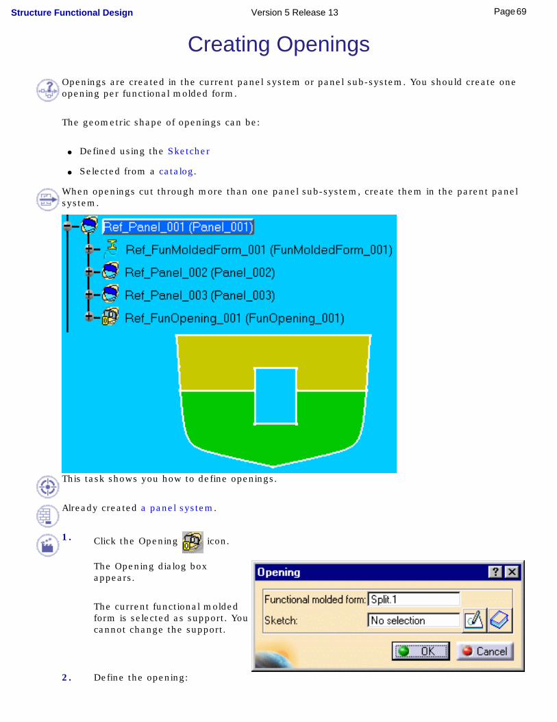
Creating OpeningsOpenings are created in the current panel system or panel sub-system. You should create one opening per functional molded form.
The geometric shape of openings can be:
● Defined using the Sketcher
● Selected from a catalog.
When openings cut through more than one panel sub-system, create them in the parent panel system.
This task shows you how to define openings.
Already created a panel system.
1. Click the Opening icon.
The Opening dialog box appears.
The current functional molded form is selected as support. You cannot change the support.
2. Define the opening:
69Page Structure Functional Design Version 5 Release 13

Using the Sketcher
● Click the sketcher icon
in the dialog box to enter the Sketcher workbench and sketch your opening.
● Exit the sketcher when done.
● Click OK in the Opening dialog box to create the opening.
The opening is created and is identified in the specification tree.
From a Catalog
A sample catalog of different types of opening is provided with the product. The opening catalog is a project resource and as such is managed by the system administrator.
● Click the catalog icon in the dialog box.
The Catalog Browser dialog box opens letting you browse and preview the contents of the current catalog.
70Page Structure Functional Design Version 5 Release 13
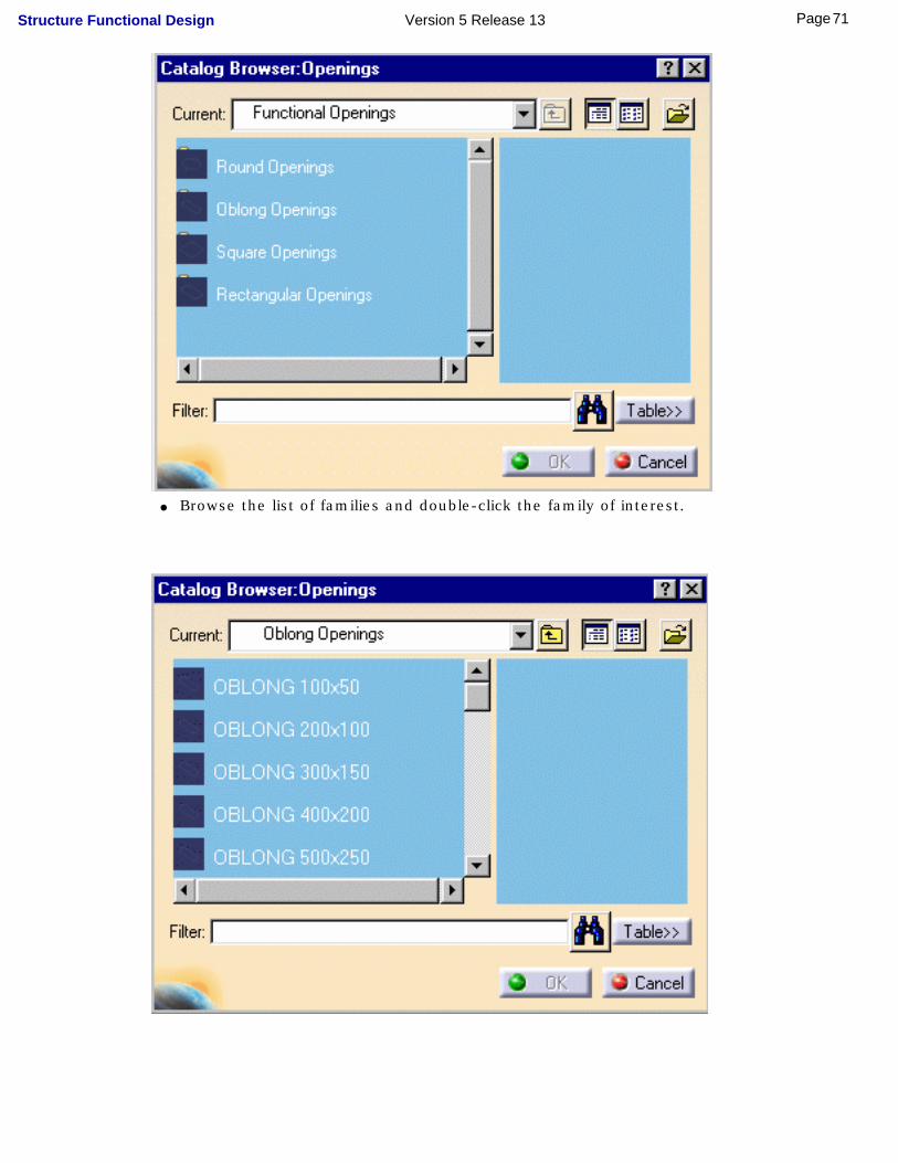
● Browse the list of families and double-click the family of interest.
71Page Structure Functional Design Version 5 Release 13

● Browse the list of holes and select the one of interest.
● Click OK in the Catalog Browser.
The hole is positioned at the center of gravity of the surface.
● Use the 3D compass to position it as desired.
● Click OK in the Opening dialog box to create the opening.
72Page Structure Functional Design Version 5 Release 13
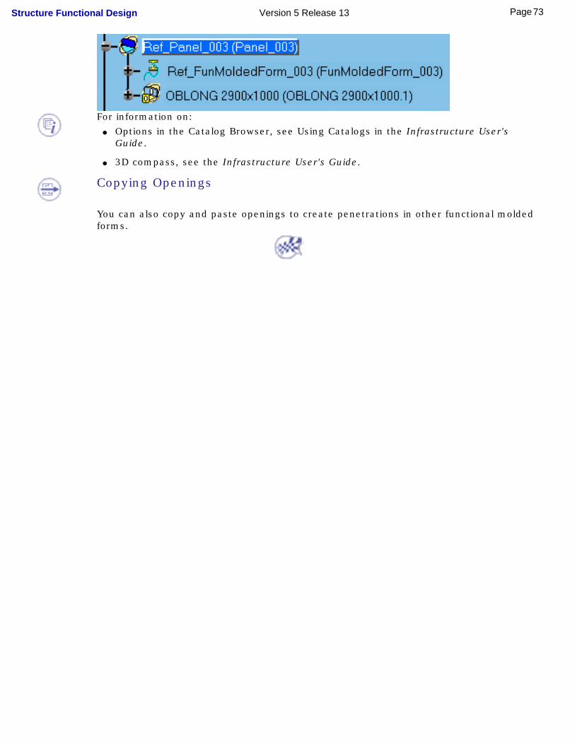
For information on: ● Options in the Catalog Browser, see Using Catalogs in the Infrastructure User's
Guide.
● 3D compass, see the Infrastructure User's Guide.
Copying Openings
You can also copy and paste openings to create penetrations in other functional molded forms.
73Page Structure Functional Design Version 5 Release 13

Editing Plates, Stiffeners & OpeningsEdit functional plates: Right-click the plate in the specification tree and select Definition from the contextual menu, then make appropriate changesEdit insert plates: Right-click the plate in the specification tree and select Definition from the contextual menu to change plate characteristics or Remove to delete the plateEdit stiffeners: Right-click the stiffener in the specification tree to change the definition or flip the section; activate the stiffener system and click the Stiffener icon to edit stiffener tracesEdit openings: right-click the opening in the specification tree and select Definition from the contextual menu to change opening characteristics or Remove to delete the opening
74Page Structure Functional Design Version 5 Release 13

Editing Functional PlatesYou can edit the definition of functional plates to change plate:
● merge characteristics
● material
● thickness
● offset
● direction of extrusion.
This task shows you how to change functional plate characteristics.
No sample document is provided.
1.Right-click the plate you want to edit in the specification tree and select Definition from the contextual menu.
Or,
Select the Products selection icon and right-
click the plate in the geometry area, then select Definition from the contextual menu.
If you have created a large number of structures, right-click the plate of interest in the geometry area then select Center Graph command to find your structure in the specification tree.
The Functional Plate dialog box appears listing current plate characteristics.
2.To add straking surfaces to the existing definition, simply select them.
The number of elements in the Support field is incremented in consequence.
75Page Structure Functional Design Version 5 Release 13

3.To remove or replace straking surfaces in the functional plate definition:
● Click the List icon or right-click the Support field and select Elements list from the
contextual menu
● Select the surface you want to remove or replace
● Click Remove to delete the surface from the definition
● Click Replace and select another surface of the straking grid
● Click Close when done.
4.Make other changes in the dialog box then click Apply to preview the results or OK when done.Editing Plate Definition using Multiple Selection
You can edit the definition of several functional plates in one go by Cntrl-clicking plates in the specification tree. If plates have different characteristics, only those edited are changed.
76Page Structure Functional Design Version 5 Release 13
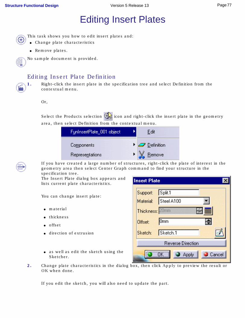
Editing Insert Plates This task shows you how to edit insert plates and:
● Change plate characteristics
● Remove plates.
No sample document is provided.
Editing Insert Plate Definition1. Right-click the insert plate in the specification tree and select Definition from the
contextual menu.
Or,
Select the Products selection icon and right-click the insert plate in the geometry
area, then select Definition from the contextual menu.
If you have created a large number of structures, right-click the plate of interest in the geometry area then select Center Graph command to find your structure in the specification tree.The Insert Plate dialog box appears and lists current plate characteristics.
You can change insert plate:
● material
● thickness
● offset
● direction of extrusion
● as well as edit the sketch using the Sketcher.
2. Change plate characteristics in the dialog box, then click Apply to preview the result or OK when done.
If you edit the sketch, you will also need to update the part.
77Page Structure Functional Design Version 5 Release 13

Using Multiple Selection
You can edit the definition of several insert plates in one go by Cntrl-clicking plates in the specification tree. If plates have different characteristics, only those edited are changed.
Removing Insert Plates1. Right-click the insert plate in the specification tree and select Remove from the
contextual menu.
The insert plate is deleted and any functional plates updated.
78Page Structure Functional Design Version 5 Release 13
Editing Stiffeners You can:
● Modify the type, section, anchor point and orientation of stiffeners (Definition)
● Flip asymmetric section (Flip)
● Edit stiffener traces.
This task shows you how to edit stiffeners.
No sample document is provided.
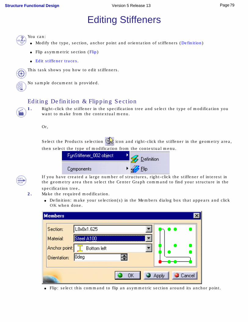
Editing Definition & Flipping Section1. Right-click the stiffener in the specification tree and select the type of modification you
want to make from the contextual menu.
Or,
Select the Products selection icon and right-click the stiffener in the geometry area,
then select the type of modification from the contextual menu.
If you have created a large number of structures, right-click the stiffener of interest in the geometry area then select the Center Graph command to find your structure in the
specification tree.2. Make the required modification.
● Definition: make your selection(s) in the Members dialog box that appears and click OK when done.
● Flip: select this command to flip an asymmetric section around its anchor point.
79Page Structure Functional Design Version 5 Release 13

Using Multiple Selection
You can edit the definition of several stiffeners in one go by Cntrl-clicking them in the specification tree. If stiffeners have different characteristics, only those edited are changed.
Note: The Flip command is not available if a multiple selection is made.
Editing Stiffener Traces1. Activate the stiffener system, then click the Stiffener icon.
The Stiffener System dialog box appears.2. Click the sketcher icon to edit traces using Sketcher capabilities.
You can trim, move, create new stiffeners, etc.3. Click OK when done.
80Page Structure Functional Design Version 5 Release 13
Editing OpeningsThis task shows you how to:
● Change opening characteristics (sketch contour or catalog shape)
● Move openings
● Remove openings.
No sample document is provided.
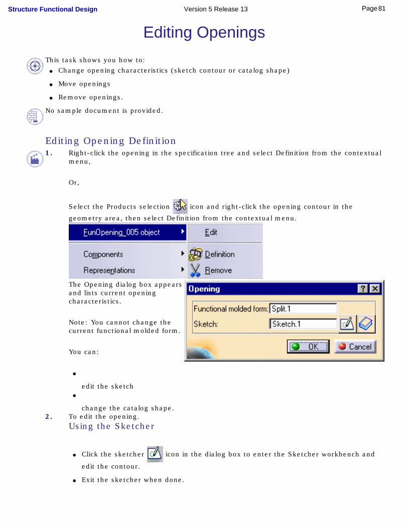
Editing Opening Definition1. Right-click the opening in the specification tree and select Definition from the contextual
menu,
Or,
Select the Products selection icon and right-click the opening contour in the
geometry area, then select Definition from the contextual menu.
The Opening dialog box appears and lists current opening characteristics.
Note: You cannot change the current functional molded form.
You can:
●
edit the sketch●
change the catalog shape.2. To edit the opening.
Using the Sketcher
● Click the sketcher icon in the dialog box to enter the Sketcher workbench and
edit the contour.
● Exit the sketcher when done.
81Page Structure Functional Design Version 5 Release 13

From a Catalog
● Click the catalog icon in the dialog box to enter the Catalog Browser.
● Browse through the catalog and select the new shape you want.
● Click OK in the Catalog Browser.
3. Click OK in the Opening dialog box when done:
The opening is automatically updated.
Moving Catalog Openings1. Select the opening in the specification tree.
The 3D compass positions itself on the opening.
2. Move the compass as desired.3. Update if necessary.
Note: To move sketched openings, edit the sketch.
Removing Openings1. Right-click the opening in the specification tree and select Remove from the contextual
menu.
The opening is removed and the panel system updated.
82Page Structure Functional Design Version 5 Release 13

Shell Tools Shell tools are used to assist you in the creation of plates and stiffeners on the hull or on high-curvature surfaces.
When using shell expansion tools, you should work on hull form halves (starboard or portside surfaces) or a section of the hull form and not the complete hull form.
The imported hull form must not include faces perpendicular to the projection plane, typically the transom must be considered a bulkhead and not an integral part of the hull. Nor must the imported surface be closed, i.e. delimit a volume.
Define plate traces: lie hull flat using the Shell Expansion command, sketch plate traces then import result back using the Import Shell Expansion command
Define stiffener traces: lie hull flat using the Shell Expansion command, sketch stiffener traces then import result back using the Import Shell Expansion commandDefine shell spline traces: select a body line, click to locate point then click Add Point and repeat.
83Page Structure Functional Design Version 5 Release 13

Defining Plate TracesYou can sketch plate traces on the hull using shell expansion tools. This is done in three steps:
● Lie the hull flat in a CATDrawing document.
● Sketch traces using Drafting commands.
● Import the result back into Structure Functional Design.
This task shows you how to define plate traces on the hull using shell expansion tools.
● Already defined a plate system feature.
● Created the planes and baseline you will need using Generative Shape Design.
1. Double-click the plate system skeleton.
2. Click the Shell Expansion icon.
The Shell Expansion dialog box appears.
Plate traces are created under the skeleton of the current plate system.
3. Select the surface to which you want to add functional plates, for example, a hull half.
84Page Structure Functional Design Version 5 Release 13

It is important that you select a surface without any openings, for example if the functional surface has openings, then select the conceptual surface.
4. Select the plane onto which entities will be mapped.
This corresponds to the 2D plane of the CATDrawing.5. Select the baseline.
The baseline must be sketched in the projection plane. It is recommended that it be below the surface you want to expand.
6. Select the planes identifying the frames you want to project onto the CATDrawing.Planes must be perpendicular to the baseline. Any planes selected that are not perpendicular are ignored. The system ensures the coherence of these planes in the shell expansion drawing.
Click the List icon or right-click in the List of frames field and select Elements list from the
contextual menu to visualize the list of selected frames. You can remove, replace and add new frames as desired.
7. Click the List of decks field and select any decks or vertical planes as well as any geometric entities intersecting the hull form, for example existing plates or stiffeners, you want projected onto the shell expansion drawing.
Note: You can select curved decks as well as parts of decks provided that they are bounded by selected frames.
8. Click OK when done.The New Drawing dialog box appears.
Note: If needed, change the drawing scale.
9. Click OK in the New Drawing dialog box.
A CATDrawing opens in the Drafting workbench showing pencil lines corresponding to the projection of selected entities.
85Page Structure Functional Design Version 5 Release 13

10.Sketch plate traces using the Spline command.
Note: You do not need to save the CATDrawing containing the plate traces.
● You must sketch a regular grid: if you sketch three vertical and three horizontal traces, you must have four grid cells. If you do not have a regular grid, the import operation will only be partially successful: plate traces will be mapped but the division into cells will not be done.
● Horizontal traces must extend beyond vertical traces (and vice-versa) to ensure proper intersection in the Structure Functional Design document.
● Any traces sketched outside the projected pencil lines are not taken into account.
● Any straight vertical traces are extrapolated to the projected pencil outline.
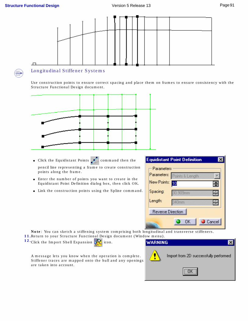
● Use construction points to ensure correct spacing and place them on frames to ensure consistency with the Structure Functional Design document.
A. Click the Equidistant Points
command then the pencil line representing a frame to create construction points along the frame.
B. Enter the number of points you want to create in the Equidistant Point Definition dialog box, then click OK.
C. Link the construction points using the Spline command.
11.Return to your Structure Functional Design document (Window menu).
86Page Structure Functional Design Version 5 Release 13
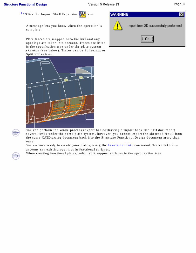
12.Click the Import Shell Expansion icon.
A message lets you know when the operation is complete.
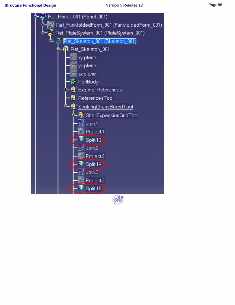
Plate traces are mapped onto the hull and any openings are taken into account. Traces are listed in the specification tree under the plate system skeleton (see below). Traces can be Spline.xxx or Split.xxx entries.
You can perform the whole process (export to CATDrawing / import back into SFD document) several times under the same plate system, however, you cannot import the sketched result from the same CATDrawing document back into the Structure Functional Design document more than once.You are now ready to create your plates, using the Functional Plate command. Traces take into account any existing openings in functional surfaces.When creating functional plates, select split support surfaces in the specification tree.
87Page Structure Functional Design Version 5 Release 13
88Page Structure Functional Design Version 5 Release 13

Defining Stiffener TracesYou can sketch stiffener traces on the hull using shell expansion tools. This is done in three steps:
● Lie the hull flat in a CATDrawing document.
● Sketch traces using Drafting commands.
● Import the result back into Structure Functional Design.
This task shows you how to define stiffener traces on the hull.
● Already defined a stiffener system feature.
● Created the planes and baseline you will need using Generative Shape Design.
1. Double-click the stiffener system skeleton.
2. Click the Shell Expansion icon.
The Shell Expansion dialog box appears.
Stiffener traces are created under the skeleton of the current stiffener system.
3. Select the surface you want to stiffen, for example, the hull.It is important that you select a surface without any openings, for example if the functional surface has openings, then select the conceptual surface.
4. Select the plane onto which entities will be mapped.
This corresponds to the 2D plane of the CATDrawing.5. Select the baseline.
The baseline must be sketched in the projection plane. It is recommended that it be below the surface you want to expand.
6. Select the planes identifying the frames you want to project onto the CATDrawing.Planes must be perpendicular to the baseline. Any planes selected that are not perpendicular are ignored. The system ensures the coherence of these planes in the shell expansion drawing.
Click the List icon or right-click in the List of frames field and select Elements list from the contextual
menu to visualize the list of selected frames. You can remove, replace and add new frames as desired.
89Page Structure Functional Design Version 5 Release 13

7. Click the List of decks field and select any decks or vertical planes as well as any geometric entities intersecting the hull form, for example existing plates or stiffeners, you want projected onto the shell expansion drawing.
Note: You can select curved decks as well as parts of decks provided that they are bounded by selected frames.
8. Click OK when done.The New Drawing dialog box appears.
Note: If needed, change the drawing scale.
9. Click OK in the New Drawing dialog box.
A CATDrawing opens in the Drafting workbench showing pencil lines corresponding to the projection of selected entities.
10.Sketch stiffener traces using the Spline command.
Any traces sketched outside the projected pencil lines are not taken into account.
Note: You do not need to save the CATDrawing containing the stiffener traces.
Transverse Stiffener System
90Page Structure Functional Design Version 5 Release 13
Longitudinal Stiffener Systems
Use construction points to ensure correct spacing and place them on frames to ensure consistency with the Structure Functional Design document.
● Click the Equidistant Points command then the
pencil line representing a frame to create construction points along the frame.
● Enter the number of points you want to create in the Equidistant Point Definition dialog box, then click OK.
● Link the construction points using the Spline command.
Note: You can sketch a stiffening system comprising both longitudinal and transverse stiffeners.11.Return to your Structure Functional Design document (Window menu).12.Click the Import Shell Expansion icon.
A message lets you know when the operation is complete. Stiffener traces are mapped onto the hull and any openings are taken into account.
91Page Structure Functional Design Version 5 Release 13
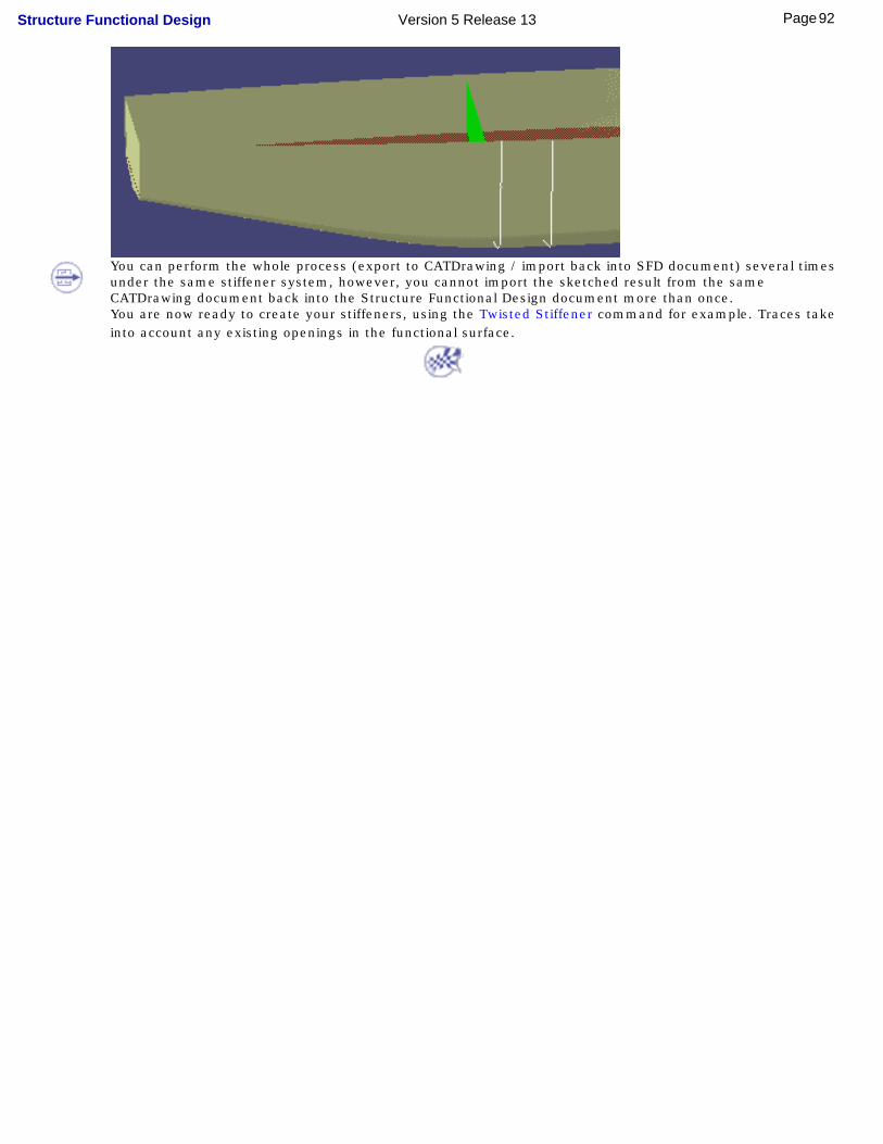
You can perform the whole process (export to CATDrawing / import back into SFD document) several times under the same stiffener system, however, you cannot import the sketched result from the same CATDrawing document back into the Structure Functional Design document more than once.You are now ready to create your stiffeners, using the Twisted Stiffener command for example. Traces take into account any existing openings in the functional surface.
92Page Structure Functional Design Version 5 Release 13

Defining Shell Spline TracesThe shell spline command lets you create spline traces to assist you create twisted stiffeners on the hull.
Spline traces are based on ship sections. Spline traces pass through defined points on ship sections and can be smoothed to obtain minimum curvature if desired. It is important that the hull be a surface without any openings.
This task shows you how to create and optimize shell spline traces on the hull.
● Already defined a stiffener system feature.
● Created the ship sections you will need.
1. Double-click the stiffener system skeleton.
2. Click the Shell Spline icon.
Spline trace points are created under the active body. If desired, change the active body.The Shell Spline Definition dialog box appears.
93Page Structure Functional Design Version 5 Release 13

3. Select a ship section as support curve.4. Define a point on the section:
● Click to locate the point
● Select an existing point
● Select a line intersecting the ship section to create a point at the intersection
● Create a point at a specified distance from a reference (see below).
94Page Structure Functional Design Version 5 Release 13
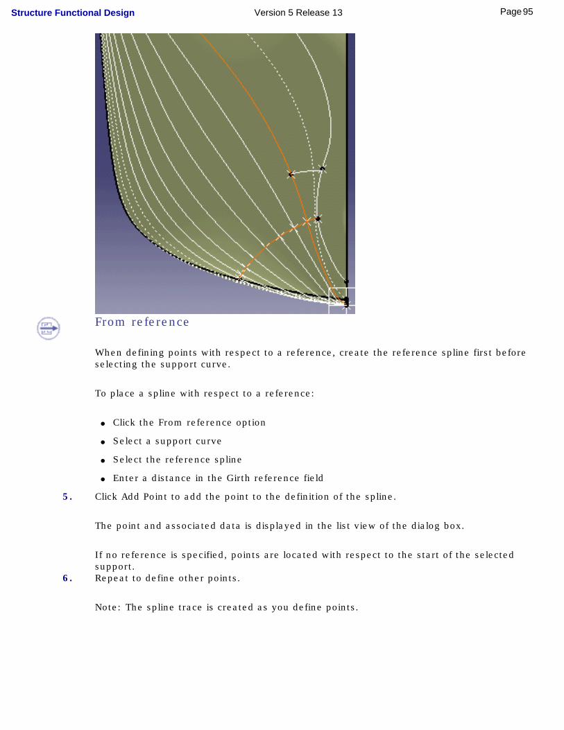
From reference
When defining points with respect to a reference, create the reference spline first before selecting the support curve.
To place a spline with respect to a reference:
● Click the From reference option
● Select a support curve
● Select the reference spline
● Enter a distance in the Girth reference field
5. Click Add Point to add the point to the definition of the spline.
The point and associated data is displayed in the list view of the dialog box.
If no reference is specified, points are located with respect to the start of the selected support.
6. Repeat to define other points.
Note: The spline trace is created as you define points.
95Page Structure Functional Design Version 5 Release 13

● Add point after or Add point before options let you order the points through which the spline passes.
● Remove Point lets you delete unwanted points.
● Reverse Direction lets you invert the sign of the distance value.
● To move a point:
1. Select the line containing the point you want to move in the list view of the dialog box.
2. Click the Element field.3. Define a new point.
96Page Structure Functional Design Version 5 Release 13

7. If desired, select the Normal to curve option to create a spline trace such that spline tangents are normal to the ship section at all points.
8. Click OK in the Shell Spline Definition dialog box when done. Spline traces are edited via the Generative Shape Design workbench.
You are now ready to create your twisted stiffeners.
97Page Structure Functional Design Version 5 Release 13

Exporting Wireframe SkeletonsThis task shows you how to export simplified wireframe geometry (skeleton and section) of your structures. Two formats are proposed:
● STEP AP203 (only if you have the appropriate license)
● CATPart.
1. Click the Export
icon.
The Save As dialog box appears.
2. Click the Save as type list and select the desired format.
You can save the simplified wireframe geometry as: ● a V5 CATPart (.CATPart). The CATPart is added to the original document.
● a STEP AP203 document (.stp) if you have the appropriate license.
If you don't have a STEP AP203 license, then this format is not proposed and you can only save the skeleton as a CATPart document.
3. For a STEP document, specify the location of the document to be saved and, if necessary, enter a file name.
4.Click Save to save the skeleton in a file in the desired format.
The STEP format lets you exchange data with other CAD systems to, for example, perform FEM analysis.
98Page Structure Functional Design Version 5 Release 13
Splitting Plates & Shapes
You can split one or more plates and shapes by one or more wireframe elements (surfaces and curves).
This task shows how to split a shape.
No sample document is provided.
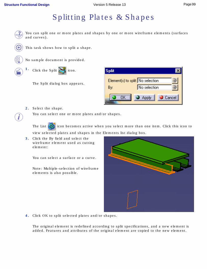
1. Click the Split icon.
The Split dialog box appears.
2. Select the shape.
You can select one or more plates and/or shapes.
The List icon becomes active when you select more than one item. Click this icon to
view selected plates and shapes in the Elements list dialog box.
3. Click the By field and select the wireframe element used as cutting element:
You can select a surface or a curve.
Note: Multiple-selection of wireframe elements is also possible.
4. Click OK to split selected plates and/or shapes.
The original element is redefined according to split specifications, and a new element is added. Features and attributes of the original element are copied to the new element.
99Page Structure Functional Design Version 5 Release 13

You can also select the plates and/or shapes you want to split before clicking the Split icon. The Split dialog box opens and you can then select the cutting element. Click OK when done.
100Page Structure Functional Design Version 5 Release 13
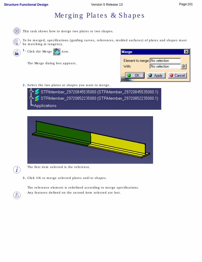
Merging Plates & Shapes
This task shows how to merge two plates or two shapes.
To be merged, specifications (guiding curves, references, molded surfaces) of plates and shapes must be matching in tangency.
1. Click the Merge icon.
The Merge dialog box appears.
2. Select the two plates or shapes you want to merge.
The first item selected is the reference.
3. Click OK to merge selected plates and/or shapes.
The reference element is redefined according to merge specifications.
Any features defined on the second item selected are lost.
101Page Structure Functional Design Version 5 Release 13

You can also select both plates or shapes before clicking the Merge icon. The first item selected is the reference.
102Page Structure Functional Design Version 5 Release 13

Creating Plane SystemsThe Plane System command provides tools letting you define a number of planes in a given direction. Planes can then be used as reference planes or supports when creating other items.
In structure applications, you can, for example, define reference planes in each ship direction to assist you place structural elements. You must define one plane system for each direction. This task shows you how to create a regular asymmetric, a irregular asymmetric and a semi-regular plane system.
1.Click the Plane System icon.
In the Generative Shape Design workbench, this icon is to be found in the Tools toolbar. You can also select Insert -> Advanced Replication Tools -> Plane System...
In Structure Functional Design, switch to the Generative Shape Design workbench.
The Plane System dialog box appears.
103Page Structure Functional Design Version 5 Release 13

3.Select the type of plane system you want to create:
Five types are available:
● Regular symmetric
● Regular asymmetric
● Semi-regular
● Irregular symmetric
● Irregular asymmetric.
Symmetric Plane Systems
Symmetric plane systems are created in similar fashion to asymmetric plane systems. The difference being that they have the same number of planes on either side of the origin.
Creating a Regular Asymmetric Plane System
4.Select a plane or a line to define the direction of the plane system.If you select a plane, the center of the plane is automatically taken as the origin of the plane system and an arrow appears showing the direction.
You can, if desired, change the origin.
104Page Structure Functional Design Version 5 Release 13

5.If you selected a line, select a point to define the origin,
Or,
If you selected a plane and want to change the origin, click the Origin field and select a point.
● Use the Reverse button in the dialog box or select the arrow in the geometry area to invert the direction.
● The contextual menus in Direction and Origin fields let you create appropriate geometry directly without having to exit the current command.
6.Specify the primary subset: ● Specify the distance between two planes in the Spacing field.
● Enter a prefix identifying all planes in this set.Planes are identified by this prefix plus a positive or negative number that increments away from the origin. Plane numbers are positive in the direction of the plane system. The origin is identified by prefix.0.
● Specify the number of planes.The number you enter is the number of planes you want to create on either side of the origin. Note that the number of planes does not include the plane at the origin.
7.(Optional) Check Allow secondary subset to group a number of planes in the primary subset together and create a secondary subset:
● Specify the step. For example, enter 4. Every fourth primary subset plane will belong to the secondary subset.
● Enter a prefix identifying all planes in this set.
Notes: The plane at the origin always belongs to the primary subset.Select the subset in the specification tree to visualize all planes in this set in the geometry area.
8.Click OK when done to create a plane system along the specified direction.
105Page Structure Functional Design Version 5 Release 13
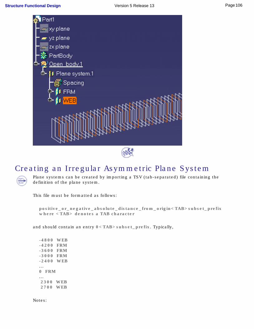
Creating an Irregular Asymmetric Plane SystemPlane systems can be created by importing a TSV (tab-separated) file containing the definition of the plane system.
This file must be formatted as follows:
positive_or_negative_absolute_distance_from_origin<TAB>subset_prefixwhere <TAB> denotes a TAB character
and should contain an entry 0<TAB>subset_prefix. Typically,
-4800 WEB-4200 FRM-3600 FRM-3000 FRM-2400 WEB...0 FRM... 2300 WEB 2700 WEB
Notes:
106Page Structure Functional Design Version 5 Release 13
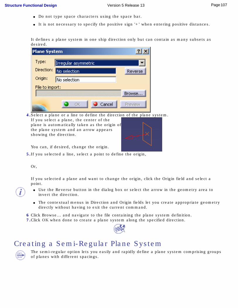
● Do not type space characters using the space bar.
● It is not necessary to specify the positive sign '+' when entering positive distances.
It defines a plane system in one ship direction only but can contain as many subsets as desired.
4.Select a plane or a line to define the direction of the plane system.If you select a plane, the center of the plane is automatically taken as the origin of the plane system and an arrow appears showing the direction.
You can, if desired, change the origin.
5.If you selected a line, select a point to define the origin,
Or,
If you selected a plane and want to change the origin, click the Origin field and select a point.
● Use the Reverse button in the dialog box or select the arrow in the geometry area to invert the direction.
● The contextual menus in Direction and Origin fields let you create appropriate geometry directly without having to exit the current command.
6 Click Browse... and navigate to the file containing the plane system definition.7.Click OK when done to create a plane system along the specified direction.
Creating a Semi-Regular Plane System The semi-regular option lets you easily and rapidly define a plane system comprising groups
of planes with different spacings.
107Page Structure Functional Design Version 5 Release 13

4.Select a plane or a line to define the direction of the plane system.If you select a plane, the center of the plane is automatically taken as the origin of the plane system and an arrow appears showing the direction.
You can, if desired, change the origin.
5.If you selected a line, select a point to define the origin,
Or,
If you selected a plane and want to change the origin, click the Origin field and select a point.
● Use the Reverse button in the dialog box or select the arrow in the geometry area to invert the direction.
● The contextual menus in Direction and Origin fields let you create appropriate geometry directly without having to exit the current command.
108Page Structure Functional Design Version 5 Release 13
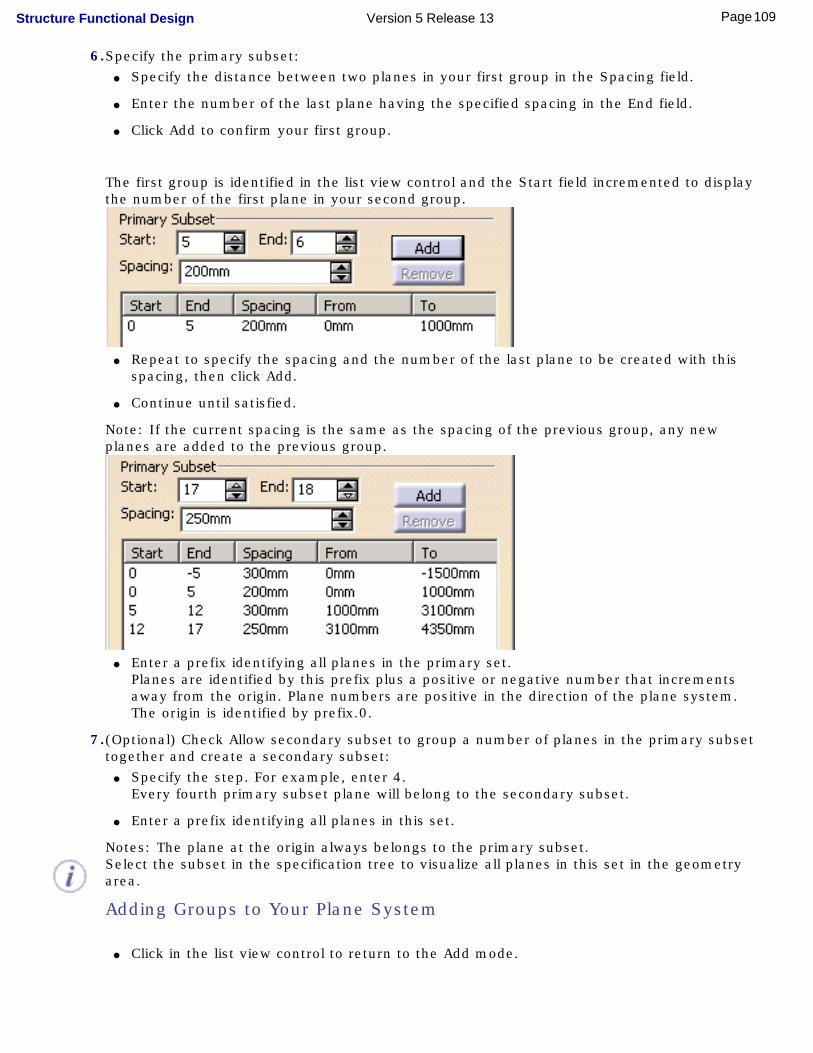
6.Specify the primary subset: ● Specify the distance between two planes in your first group in the Spacing field.
● Enter the number of the last plane having the specified spacing in the End field.
● Click Add to confirm your first group.
The first group is identified in the list view control and the Start field incremented to display the number of the first plane in your second group.
● Repeat to specify the spacing and the number of the last plane to be created with this
spacing, then click Add.
● Continue until satisfied.
Note: If the current spacing is the same as the spacing of the previous group, any new planes are added to the previous group.
● Enter a prefix identifying all planes in the primary set.
Planes are identified by this prefix plus a positive or negative number that increments away from the origin. Plane numbers are positive in the direction of the plane system. The origin is identified by prefix.0.
7.(Optional) Check Allow secondary subset to group a number of planes in the primary subset together and create a secondary subset:
● Specify the step. For example, enter 4. Every fourth primary subset plane will belong to the secondary subset.
● Enter a prefix identifying all planes in this set.
Notes: The plane at the origin always belongs to the primary subset.Select the subset in the specification tree to visualize all planes in this set in the geometry area.
Adding Groups to Your Plane System
● Click in the list view control to return to the Add mode.
109Page Structure Functional Design Version 5 Release 13

Modifying Groups in Your Plane System
● Select the group you want to modify.
● Enter a new spacing value or modify the End value to change the number of planes in the group.Note: You cannot modify the Start value.
● Click Modify.
The plane system is updated. Changing the number of planes in any one group does not affect the number of planes in other groups.
Note: Click in the list view control to cancel unwanted modifications that have not been confirmed using Modify.
Removing Groups
● Select the group you want to remove.
● Click Remove.
8.Click OK when done to create a plane system along the specified direction.
110Page Structure Functional Design Version 5 Release 13
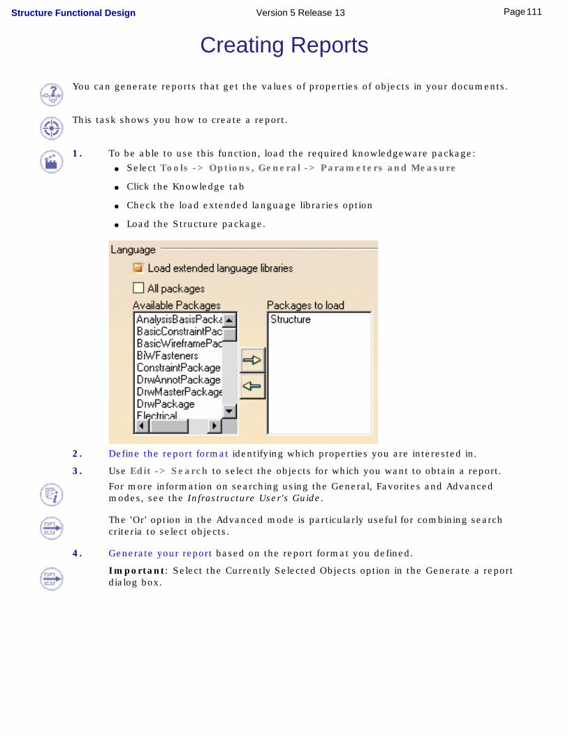
Creating ReportsYou can generate reports that get the values of properties of objects in your documents.
This task shows you how to create a report.
1. To be able to use this function, load the required knowledgeware package: ● Select Tools -> Options, General -> Parameters and Measure
● Click the Knowledge tab
● Check the load extended language libraries option
● Load the Structure package.
2. Define the report format identifying which properties you are interested in.
3. Use Edit -> Search to select the objects for which you want to obtain a report.
For more information on searching using the General, Favorites and Advanced modes, see the Infrastructure User's Guide.
The 'Or' option in the Advanced mode is particularly useful for combining search criteria to select objects.
4. Generate your report based on the report format you defined.
Important: Select the Currently Selected Objects option in the Generate a report dialog box.
111Page Structure Functional Design Version 5 Release 13

112Page Structure Functional Design Version 5 Release 13

Defining the Report Format
You use this function, together with the function described in Generating a Report, to get the values of properties of objects in a document. This task shows you how to define the report format.
Examples from the Piping Design workbench are used here. Substitute the appropriate resource or directory when working in another workbench.Before you generate a report you need to define its format. This means deciding which properties you are interested in. This report format is kept in a file which you can use to generate reports from other documents.
To use this function you must first make sure of a setting. Click Tools - Options - General - Parameters and Measure and click on the Language tab. Under Language check Load extended language libraries.
1. Click Tools - Report - Define. The Report Definition dialog box displays.
113Page Structure Functional Design Version 5 Release 13

2. Enter a report name and select a directory location. Enter a report title - you can select anything but you must enter a title.
3. Check the Show Inherited Attributes box if you want to.4. Click on the down arrow and select the dictionary related to your program.5. Select the type of object. The list of attributes you will see in Step 6 will depend on the
type you select here. However, when you generate a report you will get values for all objects in the document that have the attributes in your report format. If you want to limit the objects for which you get a report you must create a query (Step 8).
6. Select an attribute in the Attribute field and click the Add button. The attribute will be added in the window. Add as many attributes as you want to.
7. You can further refine your report by using the Edit - Search function to define a query. This will allow you to generate a report on a narrower selection of check valve, say, of a certain size, instead of all check valves in your document. The queries you create will be available for selection when you click the arrow in the Query Name field above. Detailed instructions on using the Search function can be found in the Infrastructure User Guide under Basic Tasks - Selecting Objects. Briefly, click Edit - Search to bring up the Search dialog box. Select the Advanced tab, then select a workbench, type of object and attribute you are interested in. Clicking the Add to Favorites button brings up the Create a Favorite Query dialog box, where you can name the query and save it.
114Page Structure Functional Design Version 5 Release 13

Generating a Report
This task explains how to generate a report listing values of selected properties. Before you do this you need to define the report format.
Examples form the Piping Design workbench are used here. Substitute the appropriate resource or directory when working in another workbench.
1. Click Tools - Report - Generate. The Generate Report dialog box displays.
2. Click the Open button and select the format you want to use for your report, in this case NewReport.3. If you had defined a query in your report format then check Objects From Predefined Query.4. If you select one or more objects in the document then check the option Currently Selected Objects.5. Check All Objects in Document if you want a report on all objects in your document.6. Click OK and select a format, such as HTML, when you are prompted. The report will be generated. It shows
values for all properties defined in your report format for all objects in the document that have them. Where an object does not have a property the report displays asterisks.
115Page Structure Functional Design Version 5 Release 13

7. Click Insert in Doc if you want to display these values in your document. To generate the report from a schematic and insert it in a schematic, click on the Insert in Doc button and click anywhere in your drawing. To generate the report from a 3-D document and insert it in a schematic, click on the Insert in Doc button and select the sheet or view in the specifications tree. Do not select a point in the sheet. The data will be placed at the origin of the sheet or view, and can be moved to another location.
8. Click Save As to save the report. Specify a file name and location.
116Page Structure Functional Design Version 5 Release 13
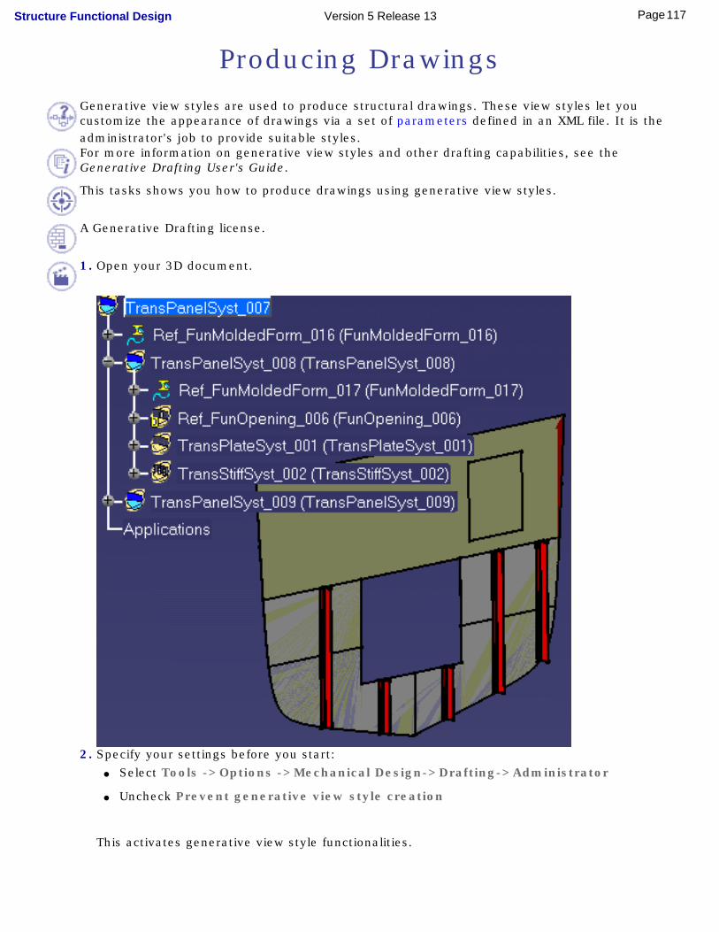
Producing DrawingsGenerative view styles are used to produce structural drawings. These view styles let you customize the appearance of drawings via a set of parameters defined in an XML file. It is the administrator's job to provide suitable styles.For more information on generative view styles and other drafting capabilities, see the Generative Drafting User's Guide.
This tasks shows you how to produce drawings using generative view styles.
A Generative Drafting license.
1. Open your 3D document.
2. Specify your settings before you start: ● Select Tools ->Options ->Mechanical Design->Drafting->Administrator
● Uncheck Prevent generative view style creation
This activates generative view style functionalities.
117Page Structure Functional Design Version 5 Release 13
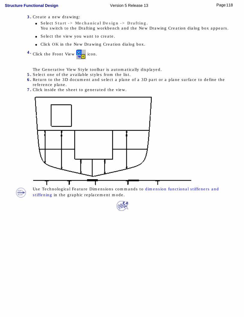
3. Create a new drawing: ● Select Start -> Mechanical Design -> Drafting.
You switch to the Drafting workbench and the New Drawing Creation dialog box appears.
● Select the view you want to create.
● Click OK in the New Drawing Creation dialog box.
4. Click the Front View icon.
The Generative View Style toolbar is automatically displayed. 5. Select one of the available styles from the list.
6. Return to the 3D document and select a plane of a 3D part or a plane surface to define the reference plane.
7. Click inside the sheet to generated the view.
Use Technological Feature Dimensions commands to dimension functional stiffeners and stiffening in the graphic replacement mode.
118Page Structure Functional Design Version 5 Release 13

Using Generative View StylesThis section intends to give you information about generative view style parameters for the following applications:
● Common to all applications
● Equipment Support Structures
● Structure Functional Design
● Ship Structure Detail Design.
Customizing these parameters is an administrator task. The following sample XML files are supplied:
● EquipmentSupportStructureSample.xml
● StructureFunctionalSample.xml
● StructureDetailSample.xml
Sample files are located in ../OS/startup/EquipmentAndSystems/DrawingExtraction/GVSSamples.
It is recommended that the administrator customize these files. When finished, files must be placed by default in ../OS/resources/standard/generativeparameters to make them available to the user.The administrator must also set the generative parameter "wireframe" in the DefaultGenerativeStyle.xml to Yes so that the user obtains suitable drawings using generative view styles.
Appropriate application licenses including one for Generative Drafting are required.
For information on how to customize parameters, how to create views using generative view styles, or more generally on generative view styles, see the Generative Drafting User's Guide.
Common Symbols
You can customize generative view style parameters for the datum line and connections. These parameters are shared by all structure applications.
Datum Line
119Page Structure Functional Design Version 5 Release 13

Parameter Value Description
ShowDatumLine Yes/No Specifies whether or not to show the datum line.No (default value): No datum lineYes: Shows the datum line
RestrictedToTheBoundingBox Yes/No Specifies whether or not to limit the datum line to the bounding box of generated objects.No (default value): No restrictionYes: Restricts datum line to the bounding box
GridsetPosition 0/1 Specifies the location of the datum line on the drawing:0 (default value): Datum line is generated in the same location as the set of planes1: Datum line is generated to the left of or below the view
HorizontalOffset real Specifies the horizontal datum line offset from the view.Default value: 20 mm
VerticalOffset real Specifies the vertical datum line offset from the view.Default value: 20 mm
GridSetLineType integer Specifies the linetype to use for the datum line.Default value: 1 (solid linetype).
TickSize real Specifies the size (in mm) of tick marks representing frames.Default value: 2.0
AnnotationStyle integer Specifies how to annotate frame tick marks.0: No annotation1 (default value): Frame names2: Offset from origin including units3: Offset from origin, no units given
AnnotationSize real Specifies the size (in mm) of annotations.Default value: 2.0 if model units for length are mm.
If model units for length are cm, set the size to 0.2
AnnotationStep integer Specifies at what intervals to place frame text annotations.Default value: 1 - each tick mark has a frame annotation.
AnnotationStart integer Specifies starting frame for text annotations.Default value: 1
ConnectionParameter Value Description
120Page Structure Functional Design Version 5 Release 13
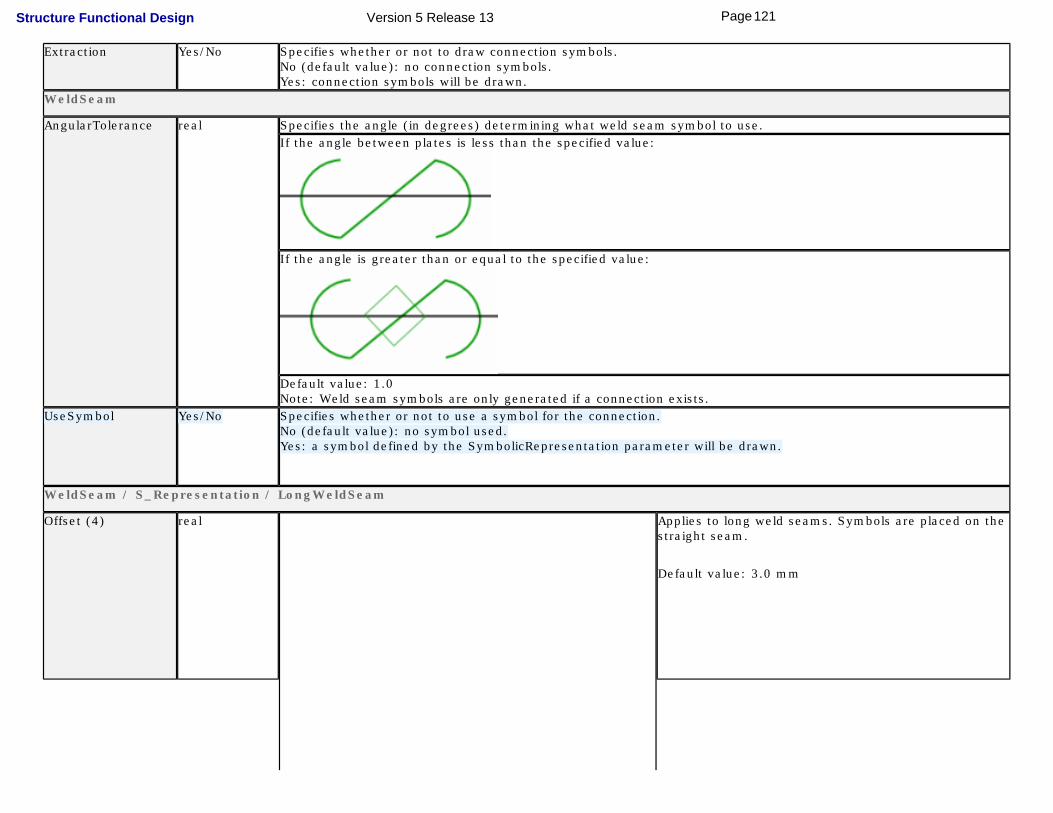
Extraction Yes/No Specifies whether or not to draw connection symbols.No (default value): no connection symbols.Yes: connection symbols will be drawn.
WeldSeam
AngularTolerance real Specifies the angle (in degrees) determining what weld seam symbol to use. If the angle between plates is less than the specified value:
If the angle is greater than or equal to the specified value:
Default value: 1.0Note: Weld seam symbols are only generated if a connection exists.
UseSymbol Yes/No Specifies whether or not to use a symbol for the connection.No (default value): no symbol used.Yes: a symbol defined by the SymbolicRepresentation parameter will be drawn.
WeldSeam / S_Representation / LongWeldSeam
Offset (4) real Applies to long weld seams. Symbols are placed on the straight seam.
Default value: 3.0 mm
121Page Structure Functional Design Version 5 Release 13

Thickness (5) real Applies to long weld seams.
Default value: 3.0 mm
WeldSeam / S_Representation / ShortWeldSeam
Gap (1) real Applies to short weld seams. Symbols are positioned at each end of the curved seam.
Default value: 1mm
Length (2) real Applies to short weld seams.
Default value: 5 mm
WeldSeam / SymbolicRepresentation / WeldSeam
ChapterName character string Specifies the name of the Structure Drawing Symbols Catalog chapter containing connection symbols.Default value: Connections
The chapter must exist in the Structure Drawing Symbols Catalog which is managed as a project resource. DetailName character string Specifies the name of the symbol to represent the connection.
Default value: S_5x1
122Page Structure Functional Design Version 5 Release 13

The symbol must exist in the Structure Drawing Symbols Catalog which is managed as a project resource. WeldSeam / SymbolicRepresentation / WeldSeamWithKnuckle
ChapterName character string Specifies the name of the Structure Drawing Symbols Catalog chapter containing connection symbols.Default value: Connections
The chapter must exist in the Structure Drawing Symbols Catalog which is managed as a project resource. DetailName character string Specifies the name of the symbol to represent the knuckle connection.
Default value: SwKnuckle_5x1
The symbol must exist in the Structure Drawing Symbols Catalog which is managed as a project resource. FontedBulkhead
StraightLineType integer Specifies the linetype of the line representing hidden plates (fonted bulkheads).Note: Fonted bulkhead lines are only generated if a connection exists.
The administrator must create a bi-dimensional plate linetype of a crosshatch pattern:● Select Tools -> Standards to start the standards editor.
● Select the Drafting category and open the standard of interest from the File drop-down list.
● Expand nodes and select the LineTypes parameter, then set a bi-dimensional linetype of a crosshatch pattern in the right-hand pane of the dialog box.
CurvedLineType integer Specifies the linetype of the line representing hidden curved plates (fonted bulkheads). The administrator must specify an existing mono-dimensional linetype.Note: Fonted bulkhead lines are only generated if a connection exists.
CurvedLineThickness integer Specifies the thickness to use for hidden curved plates.
Equipment Support StructuresYou can customize generative view style parameters for:
● Members
● Plates.
123Page Structure Functional Design Version 5 Release 13
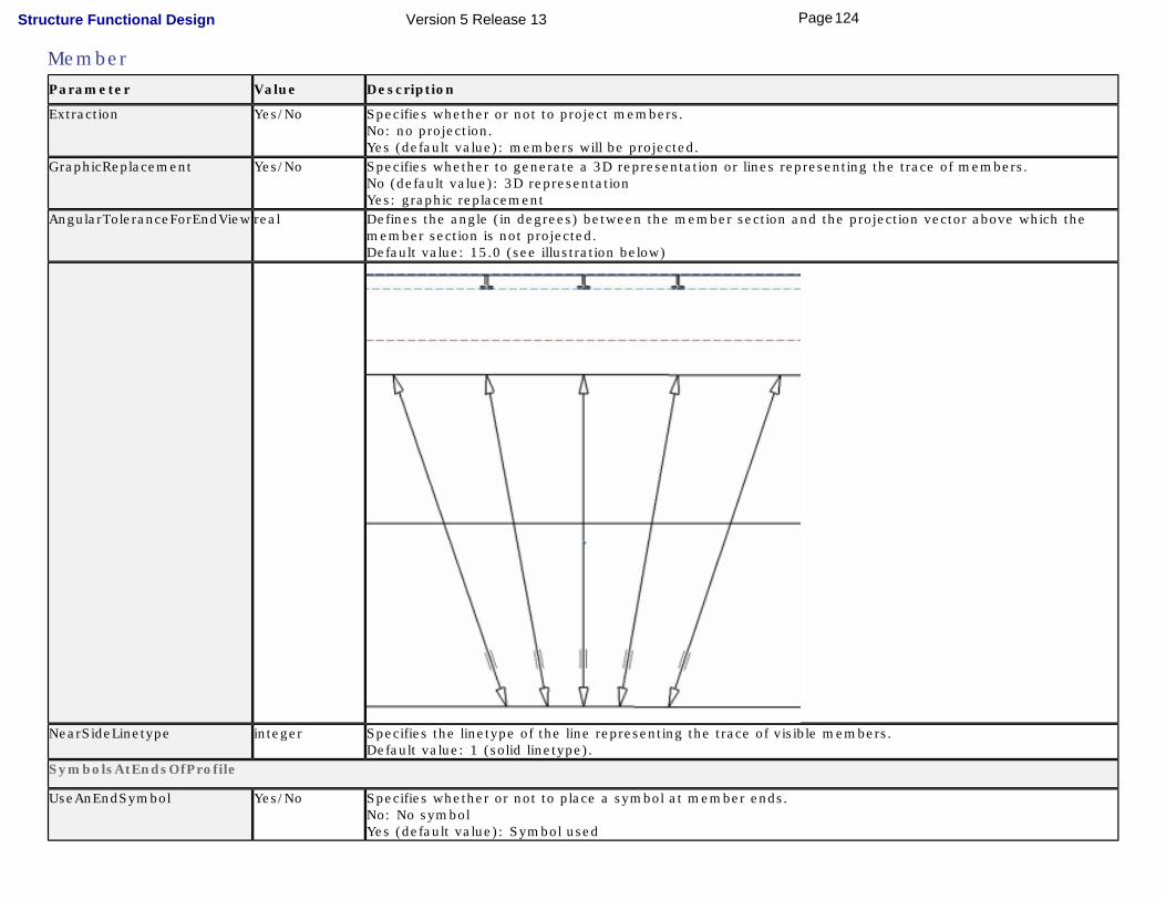
MemberParameter Value Description
Extraction Yes/No Specifies whether or not to project members.No: no projection.Yes (default value): members will be projected.
GraphicReplacement Yes/No Specifies whether to generate a 3D representation or lines representing the trace of members.No (default value): 3D representationYes: graphic replacement
AngularToleranceForEndView real Defines the angle (in degrees) between the member section and the projection vector above which the member section is not projected. Default value: 15.0 (see illustration below)
NearSideLinetype integer Specifies the linetype of the line representing the trace of visible members.Default value: 1 (solid linetype).
SymbolsAtEndsOfProfile
UseAnEndSymbol Yes/No Specifies whether or not to place a symbol at member ends.No: No symbolYes (default value): Symbol used
124Page Structure Functional Design Version 5 Release 13
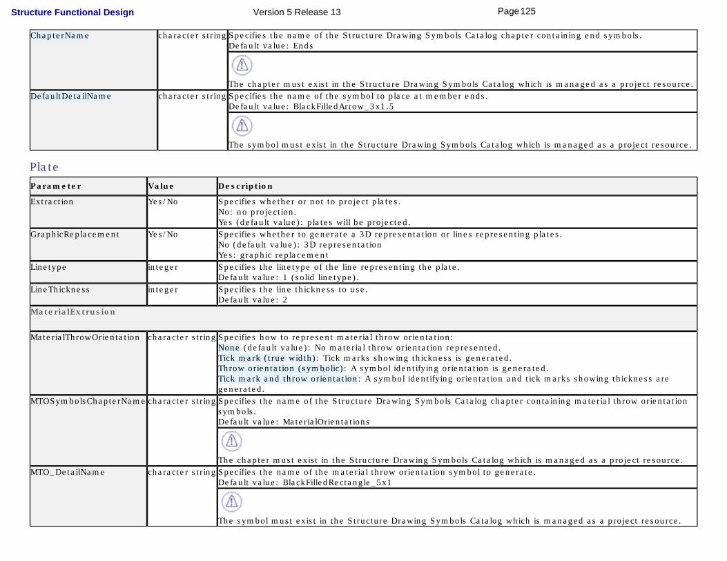
ChapterName character string Specifies the name of the Structure Drawing Symbols Catalog chapter containing end symbols.Default value: Ends
The chapter must exist in the Structure Drawing Symbols Catalog which is managed as a project resource. DefaultDetailName character string Specifies the name of the symbol to place at member ends.
Default value: BlackFilledArrow_3x1.5
The symbol must exist in the Structure Drawing Symbols Catalog which is managed as a project resource.
PlateParameter Value Description
Extraction Yes/No Specifies whether or not to project plates.No: no projection.Yes (default value): plates will be projected.
GraphicReplacement Yes/No Specifies whether to generate a 3D representation or lines representing plates.No (default value): 3D representationYes: graphic replacement
Linetype integer Specifies the linetype of the line representing the plate.Default value: 1 (solid linetype).
LineThickness integer Specifies the line thickness to use.Default value: 2
MaterialExtrusion
MaterialThrowOrientation character string Specifies how to represent material throw orientation:None (default value): No material throw orientation represented.Tick mark (true width): Tick marks showing thickness is generated.Throw orientation (symbolic): A symbol identifying orientation is generated.Tick mark and throw orientation: A symbol identifying orientation and tick marks showing thickness are generated.
MTOSymbolsChapterName character string Specifies the name of the Structure Drawing Symbols Catalog chapter containing material throw orientation symbols.Default value: MaterialOrientations
The chapter must exist in the Structure Drawing Symbols Catalog which is managed as a project resource. MTO_DetailName character string Specifies the name of the material throw orientation symbol to generate.
Default value: BlackFilledRectangle_5x1
The symbol must exist in the Structure Drawing Symbols Catalog which is managed as a project resource.
125Page Structure Functional Design Version 5 Release 13
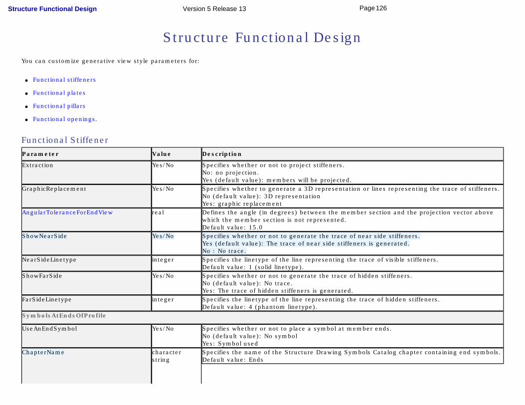
Structure Functional DesignYou can customize generative view style parameters for:
● Functional stiffeners
● Functional plates
● Functional pillars
● Functional openings.
Functional StiffenerParameter Value Description
Extraction Yes/No Specifies whether or not to project stiffeners.No: no projection.Yes (default value): members will be projected.
GraphicReplacement Yes/No Specifies whether to generate a 3D representation or lines representing the trace of stiffeners.No (default value): 3D representationYes: graphic replacement
AngularToleranceForEndView real Defines the angle (in degrees) between the member section and the projection vector above which the member section is not represented.Default value: 15.0
ShowNearSide Yes/No Specifies whether or not to generate the trace of near side stiffeners.Yes (default value): The trace of near side stiffeners is generated.No : No trace.
NearSideLinetype integer Specifies the linetype of the line representing the trace of visible stiffeners.Default value: 1 (solid linetype).
ShowFarSide Yes/No Specifies whether or not to generate the trace of hidden stiffeners.No (default value): No trace.Yes: The trace of hidden stiffeners is generated.
FarSideLinetype integer Specifies the linetype of the line representing the trace of hidden stiffeners.Default value: 4 (phantom linetype).
SymbolsAtEndsOfProfile
UseAnEndSymbol Yes/No Specifies whether or not to place a symbol at member ends.No (default value): No symbolYes: Symbol used
ChapterName character string
Specifies the name of the Structure Drawing Symbols Catalog chapter containing end symbols.Default value: Ends
126Page Structure Functional Design Version 5 Release 13

The chapter must exist in the Structure Drawing Symbols Catalog which is managed as a project resource.
DefaultDetailName character string
Specifies the name of the symbol to use at member ends.Default value: BlackFilledArrow_3x1.5
The symbol must exist in the Structure Drawing Symbols Catalog which is managed as a project resource.
MaterialExtrusion
MaterialThrowOrientation character string
Specifies how to represent material throw orientation:None (default value): No material throw orientation represented.Tick mark (true width): Tick marks showing thickness is generated.Throw orientation (symbolic): A symbol identifying orientation is generated.Tick mark and throw orientation: A symbol identifying orientation and tick marks showing thickness are generated.
MaterialExtrusion / MTO_Detail
ChapterName character string
Specifies the name of the Structure Drawing Symbols Catalog chapter containing end symbols.Default value: MaterialOrientations
The chapter must exist in the Structure Drawing Symbols Catalog which is managed as a project resource.
DefaultDetailName character string
Specifies the name of the material throw orientation symbol to use.Default value: BlackFilledRectangle_5x1
The symbol must exist in the Structure Drawing Symbols Catalog which is managed as a project resource.
DrawDetailsByProfileType Yes/No Specifies whether or not to use a symbol representing the section for material throw orientation.Yes (default value): Symbol used depends on section type. Settings for each section type are included in the GVS file.No: DefaultDetailName symbol used.
MaterialExtrusion / TickMark
OffsetFromEndOfMember (6) real Default value: 7.0Note: If the value is 0, the offset corresponds to 1/15 of the length of the stiffener.
Length (7) real Default value: 5.0Note: If the value is 0, the corresponding length is 1/15 of the length of the stiffener.
127Page Structure Functional Design Version 5 Release 13
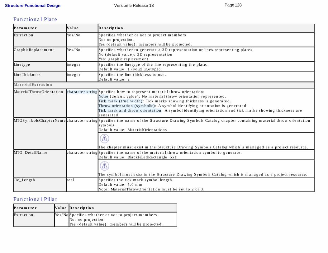
Functional PlateParameter Value Description
Extraction Yes/No Specifies whether or not to project members.No: no projection.Yes (default value): members will be projected.
GraphicReplacement Yes/No Specifies whether to generate a 3D representation or lines representing plates.No (default value): 3D representationYes: graphic replacement
Linetype integer Specifies the linetype of the line representing the plate.Default value: 1 (solid linetype).
LineThickness integer Specifies the line thickness to use.Default value: 2
MaterialExtrusion
MaterialThrowOrientation character string Specifies how to represent material throw orientation:None (default value): No material throw orientation represented.Tick mark (true width): Tick marks showing thickness is generated.Throw orientation (symbolic): A symbol identifying orientation is generated.Tick mark and throw orientation: A symbol identifying orientation and tick marks showing thickness are generated.
MTOSymbolsChapterName character string Specifies the name of the Structure Drawing Symbols Catalog chapter containing material throw orientation symbols.Default value: MaterialOrientations
The chapter must exist in the Structure Drawing Symbols Catalog which is managed as a project resource. MTO_DetailName character string Specifies the name of the material throw orientation symbol to generate.
Default value: BlackFilledRectangle_5x1
The symbol must exist in the Structure Drawing Symbols Catalog which is managed as a project resource. TM_Length real Specifies the tick mark symbol length.
Default value: 5.0 mmNote: MaterialThrowOrientation must be set to 2 or 3.
Functional PillarParameter Value Description
Extraction Yes/No Specifies whether or not to project members.No: no projection.Yes (default value): members will be projected.
128Page Structure Functional Design Version 5 Release 13
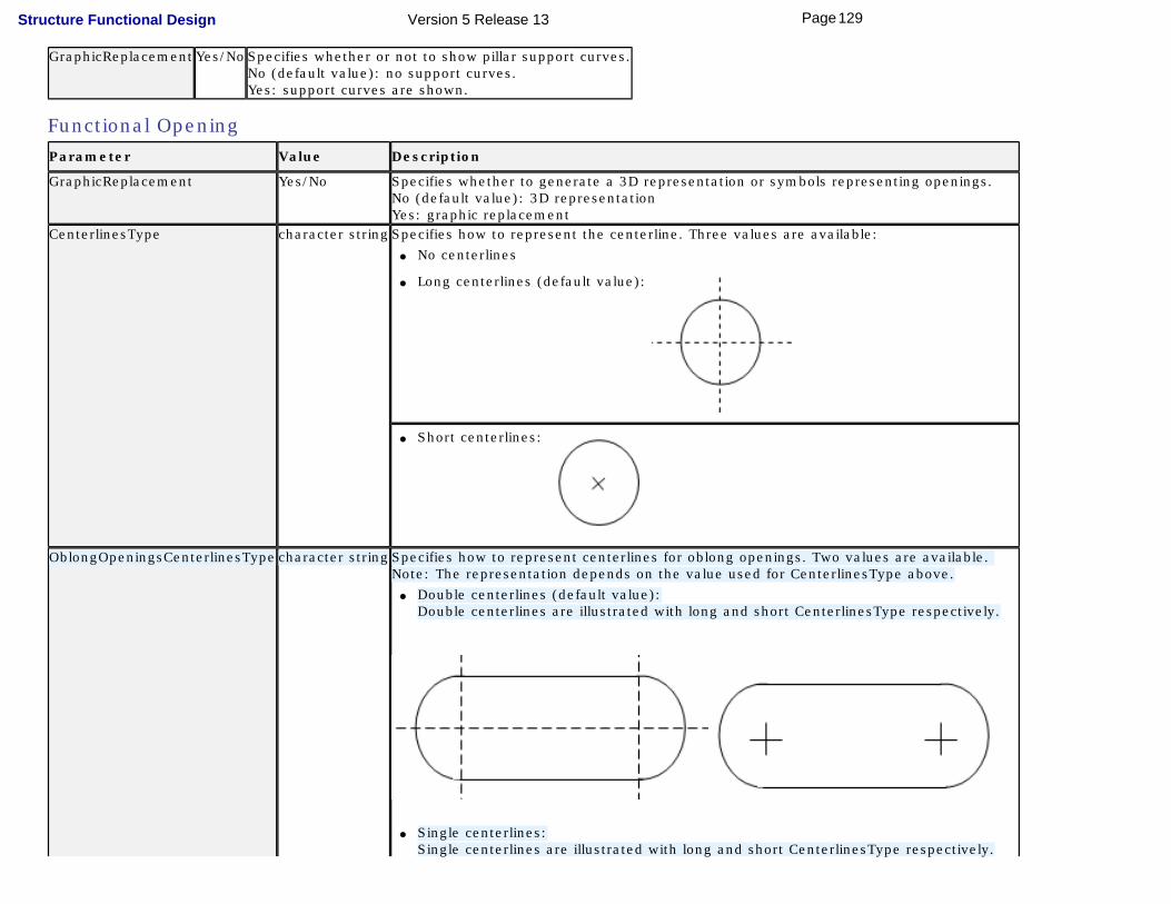
GraphicReplacement Yes/No Specifies whether or not to show pillar support curves.No (default value): no support curves.Yes: support curves are shown.
Functional OpeningParameter Value Description
GraphicReplacement Yes/No Specifies whether to generate a 3D representation or symbols representing openings.No (default value): 3D representationYes: graphic replacement
CenterlinesType character string Specifies how to represent the centerline. Three values are available:● No centerlines
● Long centerlines (default value):
● Short centerlines:
OblongOpeningsCenterlinesType character string Specifies how to represent centerlines for oblong openings. Two values are available. Note: The representation depends on the value used for CenterlinesType above.
● Double centerlines (default value):Double centerlines are illustrated with long and short CenterlinesType respectively.
● Single centerlines:Single centerlines are illustrated with long and short CenterlinesType respectively.
129Page Structure Functional Design Version 5 Release 13

ButterflyThickness real Specifies the thickness (in mm) of the butterfly symbol.Default value: 4.0
Ship Structure Detail DesignYou can customize generative view style parameters for:
● Stiffening
● Beaming
● Plating
● Inserting
● Opening
StiffeningParameter Value Description
Extraction Yes/No Specifies whether or not to project stiffeners.No: no projection.Yes (default value): members will be projected.
GraphicReplacement Yes/No Specifies whether to generate a 3D representation or lines representing the trace of stiffeners.No (default value): 3D representationYes: graphic replacement
AngularToleranceForEndView real Defines the angle (in degrees) between the member section and the projection vector above which the member section is not represented.Default value: 15.0
ShowNearSide Yes/No Specifies whether or not to generate the trace of near side stiffeners.Yes (default value): The trace of near side stiffeners is generated.No : No trace.
130Page Structure Functional Design Version 5 Release 13

NearSideLinetype integer Specifies the linetype of the line representing the trace of visible stiffeners.Default value: 1 (solid linetype).
ShowFarSide Yes/No Specifies whether or not to generate the trace of hidden stiffeners.No (default value): No trace.Yes: The trace of hidden stiffeners is generated.
FarSideLinetype integer Specifies the linetype of the line representing the trace of hidden stiffeners.Default value: 4 (phantom linetype).
MaterialExtrusion
MaterialThrowOrientation character string
Specifies how to represent material throw orientation:None (default value): No material throw orientation represented.Tick mark (true width): Tick marks showing thickness is generated.Throw orientation (symbolic): A symbol identifying orientation is generated.Tick mark and throw orientation: A symbol identifying orientation and tick marks showing thickness are generated.
MaterialExtrusion / MTO_Detail
ChapterName character string
Specifies the name of the Structure Drawing Symbols Catalog chapter containing material throw orientation symbols.Default value: MaterialOrientations
The chapter must exist in the Structure Drawing Symbols Catalog which is managed as a project resource.
DefaultDetailName character string
Specifies the name of the material throw orientation symbol to use.Default value: BlackFilledRectangle_5x1
The symbol must exist in the Structure Drawing Symbols Catalog which is managed as a project resource.
DrawDetailsByProfileType Yes/No Specifies whether or not to use a symbol representing the section for material throw orientation.Yes (default value): Symbol used depends on section type. Settings for each section type are included in the GVS file.No: DefaultDetailName symbol used.
MaterialExtrusion / TickMark
OffsetFromEndOfMember (6) real Default value: 7.0Note: If the value is 0, the offset corresponds to 1/15 of the length of the stiffener.
Length (7) real Default value: 5.0Note: If the value is 0, the corresponding length is 1/15 of the length of the stiffener.
SymbolsAtEndsOfProfile
131Page Structure Functional Design Version 5 Release 13
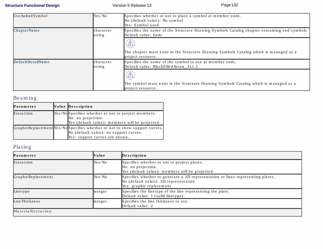
UseAnEndSymbol Yes/No Specifies whether or not to place a symbol at member ends.No (default value): No symbolYes: Symbol used
ChapterName character string
Specifies the name of the Structure Drawing Symbols Catalog chapter containing end symbols.Default value: Ends
The chapter must exist in the Structure Drawing Symbols Catalog which is managed as a project resource.
DefaultDetailName character string
Specifies the name of the symbol to use at member ends.Default value: BlackFilledArrow_3x1.5
The symbol must exist in the Structure Drawing Symbols Catalog which is managed as a project resource.
BeamingParameter Value Description
Extraction Yes/No Specifies whether or not to project members.No: no projection.Yes (default value): members will be projected.
GraphicReplacement Yes/No Specifies whether or not to show support curves.No (default value): no support curves.Yes: support curves are shown.
PlatingParameter Value Description
Extraction Yes/No Specifies whether or not to project plates.No: no projection.Yes (default value): members will be projected.
GraphicReplacement Yes/No Specifies whether to generate a 3D representation or lines representing plates.No (default value): 3D representationYes: graphic replacement
Linetype integer Specifies the linetype of the line representing the plate.Default value: 1 (solid linetype).
LineThickness integer Specifies the line thickness to use.Default value: 2
MaterialExtrusion
132Page Structure Functional Design Version 5 Release 13

MaterialThrowOrientation character string
Specifies how to represent material throw orientation:None (default value): No material throw orientation represented.Tick mark (true width): Tick marks showing thickness is generated.Throw orientation (symbolic): A symbol identifying orientation is generated.Tick mark and throw orientation: A symbol identifying orientation and tick marks showing thickness are generated.
MTOSymbolsChapterName character string
Specifies the name of the Structure Drawing Symbols Catalog chapter containing material throw orientation symbols.Default value: MaterialOrientations
The chapter must exist in the Structure Drawing Symbols Catalog which is managed as a project resource.
MTO_DetailName character string
Specifies the name of the material throw orientation symbol to use.Default value: BlackFilledRectangle_5x1
The symbol must exist in the Structure Drawing Symbols Catalog which is managed as a project resource.
TM_Length real Specifies the tick mark symbol length.Default value: 5.0 mmNote: MaterialThrowOrientation must be set to 2 or 3.
InsertingParameter Value Description
Extraction Yes/No Specifies whether or not to project members.No: no projection.Yes (default value): members will be projected.
GraphicReplacement Yes/No Specifies whether to generate a 3D representation or lines representing plates.No (default value): 3D representationYes: graphic replacement
Linetype integer Specifies the linetype of the line representing the plate.Default value: 1 (solid linetype).
LineThickness integer Specifies the line thickness to use.Default value: 2
MaterialExtrusion
MaterialThrowOrientation character string
Specifies how to represent material throw orientation:None (default value): No material throw orientation represented.Tick mark (true width): Tick marks showing thickness is generated.Throw orientation (symbolic): A symbol identifying orientation is generated.Tick mark and throw orientation: A symbol identifying orientation and tick marks showing thickness are generated.
133Page Structure Functional Design Version 5 Release 13

MTOSymbolsChapterName character string
Specifies the name of the Structure Drawing Symbols Catalog chapter containing material throw orientation symbols.Default value: MaterialOrientations
The chapter must exist in the Structure Drawing Symbols Catalog which is managed as a project resource.
MTO_DetailName character string
Specifies the name of the material throw orientation symbol to use.Default value: BlackFilledRectangle_5x1
The symbol must exist in the Structure Drawing Symbols Catalog which is managed as a project resource.
TM_Length real Specifies the tick mark symbol length.Default value: 5.0 mmNote: MaterialThrowOrientation must be set to 2 or 3.
OpeningParameter Value Description
GraphicReplacement Yes/No Specifies whether to generate a 3D representation or symbols representing openings.No (default value): 3D representationYes: graphic replacement
CenterlinesType character string Specifies how to represent the centerline. Three values are available:● No centerlines
● Long centerlines (default value)
● Short centerlines
134Page Structure Functional Design Version 5 Release 13

OblongOpeningsCenterlinesType character string Specifies how to represent centerlines for oblong openings. Two values are available. Note: The representation depends on the value used for CenterlinesType above.
● Double centerlines (default value):Double centerlines are illustrated with long and short CenterlinesType respectively.
● Single centerlines:Single centerlines are illustrated with long and short CenterlinesType respectively.
ButterflyThickness real Specifies the thickness (in mm) of the butterfly symbol.Default value: 4.0
135Page Structure Functional Design Version 5 Release 13

Managing User Sections
Sketching ProfilesDefining anchor points
Creating and Completing Parametric Section Catalogs
136Page Structure Functional Design Version 5 Release 13
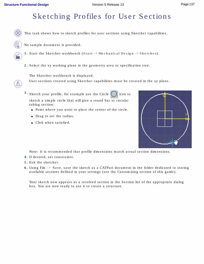
Sketching Profiles for User Sections
This task shows how to sketch profiles for user sections using Sketcher capabilities.
No sample document is provided.
1. Start the Sketcher workbench (Start ->Mechanical Design ->Sketcher).
2. Select the xy working plane in the geometry area or specification tree.
The Sketcher workbench is displayed.
User sections created using Sketcher capabilities must be created in the xy plane.
3. Sketch your profile, for example use the Circle icon to
sketch a simple circle that will give a round bar or circular tubing section:
● Point where you want to place the center of the circle.
● Drag to set the radius.
● Click when satisfied.
Note: It is recommended that profile dimensions match actual section dimensions.
4. If desired, set constraints.
5. Exit the sketcher.
6. Using File -> Save, save the sketch as a CATPart document in the folder dedicated to storing available sections defined in your settings (see the Customizing section of this guide).
Your sketch now appears as a resolved section in the Section list of the appropriate dialog box. You are now ready to use it to create a structure.
137Page Structure Functional Design Version 5 Release 13

For more information on sketching profiles and setting constraints, see the Sketcher User's Guide.
138Page Structure Functional Design Version 5 Release 13

Defining Anchor Points for User Sections
Anchor points can be defined on user-defined parametric sections.
Note: All resolved sections automatically inherit the defined anchor point.
This task shows how to define an anchor point.
No sample document is provided.
1. Edit the sketched section.
2. If the anchor point you want to define does not correspond to an existing point of the sketch, create an appropriate construction point.
3. Rename the point: ● Right-click the point and select Properties from
the contextual menu.
● Select the Feature Properties tab in the Properties dialog box.
● Rename the point using the prefix catStr, for example catStrUserAnchorPoint.
4. Exit the sketcher, then save the sketch as a CATPart document (File ->Save).
5. Return to the Structure Design workbench:
The new anchor point is automatically added to the Anchor point list. All user
anchor points are accompanied by the following symbol: to distinguish them from standard anchor points.
Anchor points WebSideLeft, WebSideRight and WebCenter are supplied with the product for L, T and bulb sections. These anchor points are considered user
anchor points and share the same anchor point symbol:
139Page Structure Functional Design Version 5 Release 13
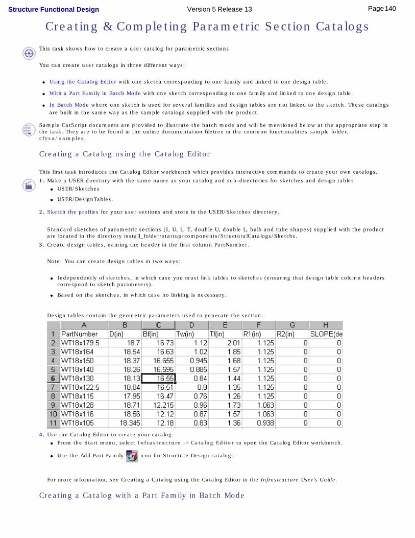
Creating & Completing Parametric Section Catalogs
This task shows how to create a user catalog for parametric sections.
You can create user catalogs in three different ways:
● Using the Catalog Editor with one sketch corresponding to one family and linked to one design table.
● With a Part Family in Batch Mode with one sketch corresponding to one family and linked to one design table.
● In Batch Mode where one sketch is used for several families and design tables are not linked to the sketch. These catalogs are built in the same way as the sample catalogs supplied with the product.
Sample CatScript documents are provided to illustrate the batch mode and will be mentioned below at the appropriate step in the task. They are to be found in the online documentation filetree in the common functionalities sample folder, cfysa/samples.
Creating a Catalog using the Catalog Editor
This first task introduces the Catalog Editor workbench which provides interactive commands to create your own catalogs.
1. Make a USER directory with the same name as your catalog and sub-directories for sketches and design tables: ● USER/Sketches
● USER/DesignTables.
2. Sketch the profiles for your user sections and store in the USER/Sketches directory.
Standard sketches of parametric sections (I, U, L, T, double U, double L, bulb and tube shapes) supplied with the product are located in the directory install_folder/startup/components/StructuralCatalogs/Sketchs.
3. Create design tables, naming the header in the first column PartNumber.
Note: You can create design tables in two ways:
● Independently of sketches, in which case you must link tables to sketches (ensuring that design table column headers correspond to sketch parameters).
● Based on the sketches, in which case no linking is necessary.
Design tables contain the geometric parameters used to generate the section.
4. Use the Catalog Editor to create your catalog: ● From the Start menu, select Infrastructure ->Catalog Editor to open the Catalog Editor workbench.
● Use the Add Part Family icon for Structure Design catalogs.
For more information, see Creating a Catalog using the Catalog Editor in the Infrastructure User's Guide.
Creating a Catalog with a Part Family in Batch Mode
140Page Structure Functional Design Version 5 Release 13
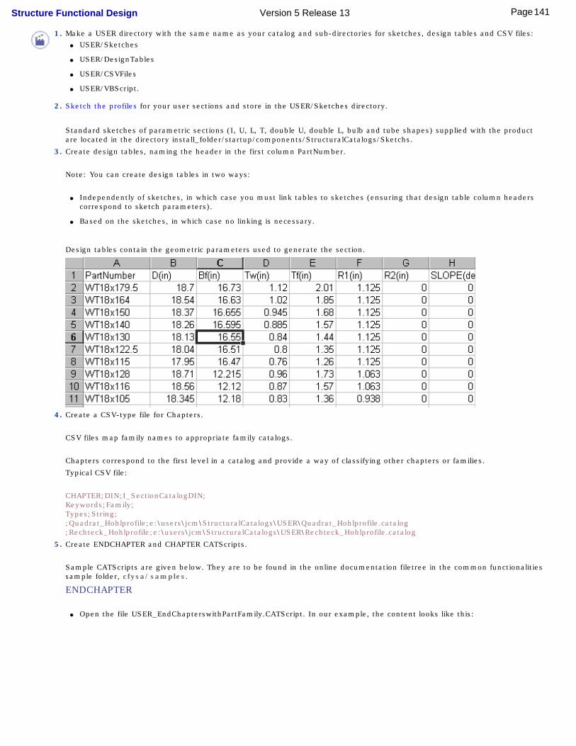
1. Make a USER directory with the same name as your catalog and sub-directories for sketches, design tables and CSV files: ● USER/Sketches
● USER/DesignTables
● USER/CSVFiles
● USER/VBScript.
2. Sketch the profiles for your user sections and store in the USER/Sketches directory.
Standard sketches of parametric sections (I, U, L, T, double U, double L, bulb and tube shapes) supplied with the product are located in the directory install_folder/startup/components/StructuralCatalogs/Sketchs.
3. Create design tables, naming the header in the first column PartNumber.
Note: You can create design tables in two ways:
● Independently of sketches, in which case you must link tables to sketches (ensuring that design table column headers correspond to sketch parameters).
● Based on the sketches, in which case no linking is necessary.
Design tables contain the geometric parameters used to generate the section.
4. Create a CSV-type file for Chapters.
CSV files map family names to appropriate family catalogs.
Chapters correspond to the first level in a catalog and provide a way of classifying other chapters or families.
Typical CSV file:
CHAPTER;DIN;I_SectionCatalogDIN;Keywords;Family;Types;String;;Quadrat_Hohlprofile;e:\users\jcm\StructuralCatalogs\USER\Quadrat_Hohlprofile.catalog;Rechteck_Hohlprofile;e:\users\jcm\StructuralCatalogs\USER\Rechteck_Hohlprofile.catalog
5. Create ENDCHAPTER and CHAPTER CATScripts.
Sample CATScripts are given below. They are to be found in the online documentation filetree in the common functionalities sample folder, cfysa/samples.
ENDCHAPTER
● Open the file USER_EndChapterswithPartFamily.CATScript. In our example, the content looks like this:
141Page Structure Functional Design Version 5 Release 13

'// COPYRIGHT DASSAULT SYSTEMES 1999'//============================================================================'//'// Language="VBSCRIPT"'// To build catalog from a parametric part'//'//============================================================================'// Major interface used:'//'// interface VB Name Remarks'// ----------- ------------ --------------'// CATIACatalogDocument CatalogDocument create catalog'//'//============================================================================Option Explicit'******************************************************************************' GLOBAL variable declarations section'******************************************************************************Dim strGInputPathDim strGOutputPath'@@@@@@@@@@@@@@@@@@@@@@@@@@@@@@@@@@@@@@@@@@@@@@@@@@@@@@'// User customizable sections'@@@@@@@@@@@@@@@@@@@@@@@@@@@@@@@@@@@@@@@@@@@@@@@@@@@@@@Const NBEndChapter = 2Dim strArrayEndChapter (2)Dim strArrayModelFile (2)Dim strArrayCatalogFile (2)'------------------------------------------------------------------------------Sub InitEndChapterArray ()'------------------------------------------------------------------------------' Name of the description displayed in the catalog browser'------------------------------------------------------------------------------
strArrayEndChapter(1) = "Tees"strArrayEndChapter(2) = "Equal Angles"
'------------------------------------------------------------------------------' Name of the .CATPart defining the sketches'------------------------------------------------------------------------------
strArrayModelFile(1) = "TShape"strArrayModelFile(2) = "LShape"
'------------------------------------------------------------------------------' Name of the generated files .catalog used in the USER.CATScript'------------------------------------------------------------------------------
strArrayCatalogFile(1) = "USER_Tees"strArrayCatalogFile(2) = "USER_Equal_Angles"
End Sub'------------------------------------------------------------------------------Sub GetPath ()'------------------------------------------------------------------------------
strGInputPath = InputBox("Path of the models directory:", _
"Input path for model files", _"e:\users\jcm\USER\Sketches\")
strGOutputPath = InputBox("Path of the catalog output directory:", _
"Output path for Catalogs", _"e:\users\jcm\USER\")
End Sub ''------------------------------------------------------------------------------Sub CATMain()'------------------------------------------------------------------------------
142Page Structure Functional Design Version 5 Release 13

Dim objCatalogDoc As DocumentDim intK As IntegerDim strChapterName As StringDim strModelName As StringDim strCatalogName As String'InitEndChapterArray'GetPath'On Error Resume NextFor intK = 1 to NBEndChapter
strModelName = strGInputPath & strArrayModelFile (intK) & ".CATPart"strChapterName = strArrayEndChapter (intK)strCatalogName = strGOutputPath & strArrayCatalogFile (intK) & ".catalog"Set objCatalogDoc = CATIA.Documents.Add("CatalogDocument")' Calls the method on Catalog to create inside the catalog document' a chapter from the Design TableobjCatalogDoc.CreateChapterFromDesignTable strChapterName , strModelName' Saves the catalog documentobjCatalogDoc.SaveAs strCatalogName' Closes the catalog documentobjCatalogDoc.Close
Next 'For intKMsgBox "Press OK to quit", 0, "CATALOG CREATION COMPLETED"
End Sub '/////////////////////////////////////////////// CATMain
● If you want to use it, copy it and change the User customizable sections to adapt them to your environment, or copy a sample CATScript from the one of the standard catalogs supplied with the product and change it.
CHAPTER
● Open the file USER_Chapter.CATScript. In our example, the content looks like this:
'// COPYRIGHT DASSAULT SYSTEMES 1999'//============================================================================'//'// Language="VBSCRIPT"'// To build catalog'//'//============================================================================'// Major interface used:'//'// interface VB Name Remarks'// ----------- ------------ --------------'// CATIACatalogDocument CatalogDocument create catalog'//'//============================================================================Option Explicit'******************************************************************************' GLOBAL variable declarations section'******************************************************************************Dim strGInputPathDim strGOutputPath'@@@@@@@@@@@@@@@@@@@@@@@@@@@@@@@@@@@@@@@@@@@@@@@@@@@@@@'// User customizable sections'@@@@@@@@@@@@@@@@@@@@@@@@@@@@@@@@@@@@@@@@@@@@@@@@@@@@@@Const NBGCSVFile = 1Dim strArrayGCSVFile (1)'------------------------------------------------------------------------------Sub InitCSVFileArray ()'------------------------------------------------------------------------------strArrayGCSVFile(1) = "USER"End Sub '/////////////////////////////////////////////// InitCSVFileArray'------------------------------------------------------------------------------Sub GetPath ()'------------------------------------------------------------------------------
strGInputPath = InputBox("Path of the catalog input directory:", _
143Page Structure Functional Design Version 5 Release 13
"Input path for CSV files", _"e:\users\jcm\USER\CsvFiles\")
strGOutputPath = InputBox("Path of the catalog output directory:", _
"Output path for Catalogs", _"e:\users\jcm\USER\")
End Sub '/////////////////////////////////////////////// GetPath'------------------------------------------------------------------------------Sub CATMain ()'------------------------------------------------------------------------------
Dim objCatalogDoc As DocumentDim intK As IntegerDim strCSVFileDim strCatalogFileInitCSVFileArrayGetPathOn Error Resume NextFor intK = 1 to NBGCSVFile
strCSVFile = strGInputPath & strArrayGCSVFile (intK) & ".csv"strCatalogFile = strGOutputPath & strArrayGCSVFile (intK) & ".catalog"Set objCatalogDoc = CATIA.Documents.Add("CatalogDocument")'---------- Generate catalogobjCatalogDoc.CreateCatalogFromcsv strCSVFile,strCatalogFile
Next 'For intKMsgBox "Press OK to quit", 0, "CATALOG CREATION COMPLETED"
End Sub '/////////////////////////////////////////////// CATMain
● If you want to use it, copy it and change the User customizable sections to adapt them to your environment, or copy a sample CATScript from the one of the standard catalogs supplied with the product and change it.
6. You are now ready to run the batch operation:
● Start a Version 5 session
● Select Tools ->Macro ->Macros...
● In the Macro dialog box, set Macro in to External File
● Select the appropriate CATScript, then click Run.
It is important to run the CATScript generating the families (END CHAPTERS) before the one generating the chapter (CHAPTER) since the chapter references the families.
Creating a Catalog in Batch Mode1. Make a USER directory with the same name as your catalog and sub-directories for sketches, design tables and CSV files:
● USER/Sketches
● USER/DesignTables (this sub-directory must be named DesignTables)
● USER/CSVFiles
● USER/VBScript.
2. Sketch the profiles for your user sections and store in the USER/Sketches directory.
Standard sketches of parametric sections (I, U, L, T, double U, double L, bulb and tube shapes) supplied with the product are located in the directory install_folder/startup/components/StructuralCatalogs/Sketchs.
3. Create design tables.
Note: Do not link design tables to sketches.
Design tables contain the geometric parameters used to generate the section.
144Page Structure Functional Design Version 5 Release 13

4. Create CSV-type files for End Chapters and Chapters.
CSV files map section names to appropriate parametric sketches.
END CHAPTER Conventions
End chapters correspond to catalog families. A family is a set of components.
For example, ENDCHAPTER: Name;Icon;DesignTable;
● If the design table is not linked to a sketch, the name of the design table must be the last parameter in the first line starting ENDCHAPTER.
● The first keyword must be Section
● The full path name of documents must be given.
Typical CSV file:
ENDCHAPTER;HEA;I_SectionStructureI;OTUA_HEA;Keywords;Section;Types;String;HEA100;HEA100;e:\users\jcm\StructuralCatalogs\Sketches\IShape.CATPartHEA120;HEA120;e:\users\jcm\StructuralCatalogs\Sketches\IShape.CATPartHEA140;HEA140;e:\users\jcm\StructuralCatalogs\Sketches\IShape.CATPart
CHAPTER Conventions
Chapters correspond to the first level in a catalog and provide a way of classifying other chapters or families.
Typical CSV file:
CHAPTER;DIN;I_SectionCatalogDIN;Keywords;Family;Types;String;;Quadrat_Hohlprofile;e:\users\jcm\StructuralCatalogs\USER\Quadrat_Hohlprofile.catalog;Rechteck_Hohlprofile;e:\users\jcm\StructuralCatalogs\USER\Rechteck_Hohlprofile.catalog
5. Create ENDCHAPTER and CHAPTER CATScripts.
Sample CATScripts are given below. They are to be found in the online documentation filetree in the common functionalities sample folder, cfysa/samples.
ENDCHAPTER
● Open the file USER_EndChaptersStandard.CATScript. In our example, the content looks like this:
'// COPYRIGHT DASSAULT SYSTEMES 1999'//============================================================================'//'// Language="VBSCRIPT"'// To build catalog'//'//============================================================================'// Major interface used:'//'// interface VB Name Remarks'// ----------- ------------ --------------'// CATIACatalogDocument CatalogDocument create catalog'//'//============================================================================Option Explicit'******************************************************************************' GLOBAL variable declarations section'******************************************************************************Dim strGInputPathDim strGOutputPath'@@@@@@@@@@@@@@@@@@@@@@@@@@@@@@@@@@@@@@@@@@@@@@@@@@@@@@'// User customizable sections'@@@@@@@@@@@@@@@@@@@@@@@@@@@@@@@@@@@@@@@@@@@@@@@@@@@@@@Const NBGCSVFile = 2Dim strArrayGCSVFile (2)'------------------------------------------------------------------------------Sub InitCSVFileArray ()'------------------------------------------------------------------------------
145Page Structure Functional Design Version 5 Release 13

strArrayGCSVFile(1) = "Equal_Angles"strArrayGCSVFile(2) = "Tees"End Sub '/////////////////////////////////////////////// InitCSVFileArray'------------------------------------------------------------------------------Sub GetPath ()'------------------------------------------------------------------------------
strGInputPath = InputBox("Path of the catalog input directory:", _
"Input path for CSV", _"e:\users\jcm\USER\CsvFiles\")
strGOutputPath = InputBox("Path of the catalog output directory:", _
"Output path for CSV", _"e:\users\jcm\USER\")
End Sub '/////////////////////////////////////////////// GetPath'------------------------------------------------------------------------------Sub CATMain ()'------------------------------------------------------------------------------
Dim objCatalogDoc As DocumentDim intK As IntegerDim strCSVFileDim strCatalogFileInitCSVFileArrayGetPathOn Error Resume NextFor intK = 1 to NBGCSVFile
strCSVFile = strGInputPath & strArrayGCSVFile (intK) & ".csv"strCatalogFile = strGOutputPath & strArrayGCSVFile (intK) & ".catalog"Set objCatalogDoc = CATIA.Documents.Add("CatalogDocument")'---------- Generate catalogobjCatalogDoc.CreateCatalogFromcsv strCSVFile,strCatalogFile
Next 'For intKMsgBox "Press OK to quit", 0, "CATALOG CREATION COMPLETED"
End Sub '/////////////////////////////////////////////// CATMain
● If you want to use it, copy it and change the User customizable sections to adapt them to your environment, or copy a sample CATScript from the one of the standard catalogs supplied with the product and change it.
CHAPTER
● Open the file USER_Chapter.CATScript. In our example, the content is as illustrated above.
● f you want to use it, copy it and change the User customizable sections to adapt them to your environment, or copy a sample CATScript from the one of the standard catalogs supplied with the product and change it.
6. You are now ready to run the batch operation:
● Start a Version 5 session
● Select Tools ->Macro ->Macros...
● In the Macro dialog box, set Macro in to External File
● Select the appropriate CATScript, then click Run.
It is important to run the CATScript generating the families (END CHAPTERS) before the one generating the chapter (CHAPTER) since the chapter references the families.
Completing Parametric Section Catalogs
146Page Structure Functional Design Version 5 Release 13

This task shows how to add sections to existing catalogs.
To add sections to existing catalogs, you must rename the path of linked documents in CSV files because these files contain the full path name. To do so, one Excel file per sample catalog containing an appropriate macro is provided. For example, the Excel file for the OTUA catalog is OTUA_hierarchy.xls. Excel files are located in the CsvFiles directory.
1 Edit the Commands sheet of the appropriate Excel file, entering the necessary information.
Note: The first sheet named Data contains all CSV files in the catalog.
2. Click Modify absolute path of pointed CATPart in CSV files to rename the path.
3. Add new sections.
4. Generate the catalog as above.
147Page Structure Functional Design Version 5 Release 13
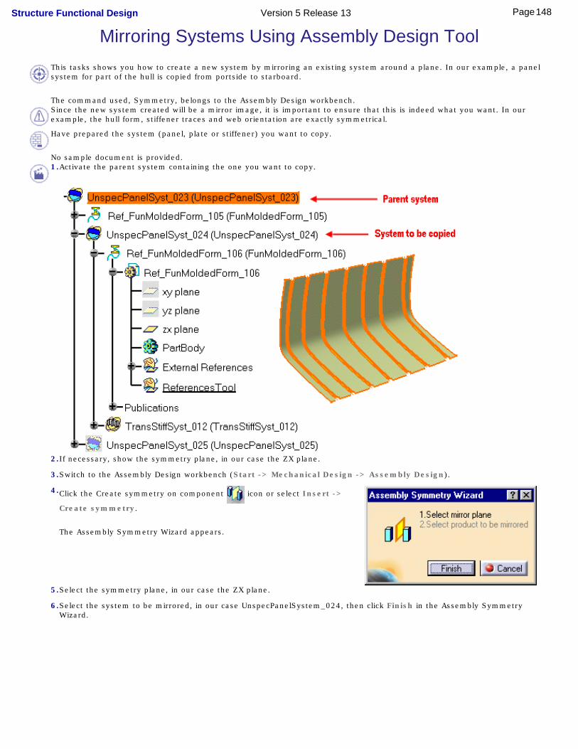
Mirroring Systems Using Assembly Design ToolThis tasks shows you how to create a new system by mirroring an existing system around a plane. In our example, a panel system for part of the hull is copied from portside to starboard.
The command used, Symmetry, belongs to the Assembly Design workbench.Since the new system created will be a mirror image, it is important to ensure that this is indeed what you want. In our example, the hull form, stiffener traces and web orientation are exactly symmetrical.
Have prepared the system (panel, plate or stiffener) you want to copy.
No sample document is provided.1.Activate the parent system containing the one you want to copy.
2.If necessary, show the symmetry plane, in our case the ZX plane.
3.Switch to the Assembly Design workbench (Start -> Mechanical Design -> Assembly Design).
4.Click the Create symmetry on component icon or select Insert ->
Create symmetry.
The Assembly Symmetry Wizard appears.
5.Select the symmetry plane, in our case the ZX plane.
6.Select the system to be mirrored, in our case UnspecPanelSystem_024, then click Finish in the Assembly Symmetry Wizard.
148Page Structure Functional Design Version 5 Release 13

The mirrored system is previewed.
The Assembly Symmetry Wizard expands and displays the list of entities that will be copied.
Keep Link Options
● Keep link in position: if checked, any changes to the position of the original system will be propagated to the mirror system.
● Keep link with geometry, if checked, any changes to the geometry of the original system will be propagated to the mirror system.
7.Click Finish to confirm the operation.
A window appears displaying the results.
8.Control the results in this window, then click Close.
A new system, the mirror copy of the first, is created.
149Page Structure Functional Design Version 5 Release 13

For more information on the Symmetry command.
150Page Structure Functional Design Version 5 Release 13

Managing Your ProjectWorking with a Cache System
Organizing Data using a Work Breakdown StructureUnderstanding Project Resource Management
About the Feature DictionaryAbout Object Naming RulesAbout Molded ConventionsAbout Project Parameters
151Page Structure Functional Design Version 5 Release 13
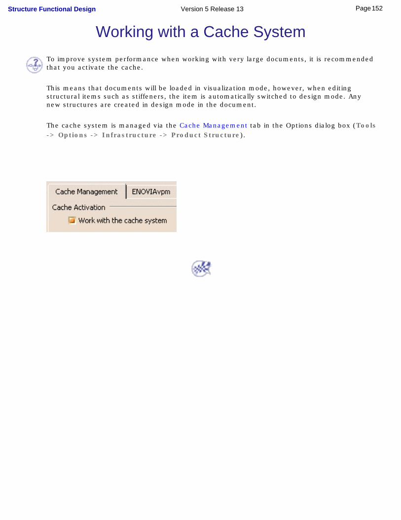
Working with a Cache SystemTo improve system performance when working with very large documents, it is recommended that you activate the cache.
This means that documents will be loaded in visualization mode, however, when editing structural items such as stiffeners, the item is automatically switched to design mode. Any new structures are created in design mode in the document.
The cache system is managed via the Cache Management tab in the Options dialog box (Tools -> Options -> Infrastructure -> Product Structure).
152Page Structure Functional Design Version 5 Release 13

Organizing Data using a Work Breakdown Structure
You can structure and organize your data using a work breakdown structure (WBS). This avoids creating intermediate component nodes in the structure tree which create an unnecessary level of instantiation.
It is recommended that you create all panel systems directly under the root product.
To take advantage of WBS:
1. Create panel systems directly under the root product.
2. Create WBS views and generic components (GCOs).
3. Organize your panel systems by dragging and dropping them under appropriate WBS views.
4. Save your document.
This enables you to load only views of interest.
153Page Structure Functional Design Version 5 Release 13
Understanding Project Resource ManagementProject resources are managed by system administrators. Typically this involves entering information such as folder paths for resources, like user dictionaries such as the feature dictionary, without which the application cannot function. What administrators enter will be visible in the Browse tab of the Project Resource Management dialog box (Tools -> Project Management), but it cannot be changed there.
A sample project resource management file is provided with this application and by default, the application will start with this file. Resources managed in this file are listed below.
Project Resources
● Feature dictionary managing object classes
● Discrete values for attributes: directory used to store discrete values of attributes.
● ID schema managing object naming rules
Structure Discipline Resources
● Project parameters: contains setup parameters for ship directions and characteristic planes
The default location for this resource is ../OS/startup/EquipmentAndSystems/Structure
● Molded conventions: contains a set of rules that give default orientations when placing structural elements
The default location for this resource is ../OS/startup/EquipmentAndSystems/Structure
● Orientation conventions: contains naming conventions for ship directions. Default conventions are USA conventions contained in sample CATStrOrientNamingUSAConv.
Sample naming conventions for European conventions is also supplied: CATStrOrientNamingEURConv.
The default location for these resources are .../OS/resources/msgcatalog
● Structure drawing symbols catalog
The default location of this resource is.../OS/startup/components/StructuralCatalogs/DrawingSymbols/Structure2DSymbols-Customization.catalog
154Page Structure Functional Design Version 5 Release 13
● Standard section catalog
The default location of this resource is .../OS/startup/components/StructuralCatalogs/AISC/AISC_StandardScale.catalog
● Structure resolved sections path: identifies the path of the folder in which the list of available sections
will be stored.There is no default location for this resource; the location shown is given as an example.
To set this path:
- Uncomment this entry- Identify the path.
It is recommended that you create an empty folder for available sections and that you identify the path to this folder in a customized project resource management file. You can also, if desired, initialize a section list for the user.
If no path is identified here, the path set in your settings is taken.
You can create a catalog of available sections and store it in ENOVIA.
● Thickness table: manages plate thicknesses. A sample table in text format is supplied. The system
administrator can modify or add to the sample thickness table, or, if needed, create a new table.
The default location of this resource is .../OS/startup/components/StructuralCatalogs/ThicknessTables/ThicknessListSample.txt
Important: If you change a thickness value in an existing design table, all plates of this thickness linked to the design table will be updated to the new value. With this in mind, you may prefer to add a row for the new thickness or create a new table.
● Structure materials catalog: defines all material-grade combinations available.
Note: Associated tiffs are not provided. This means rendering is unavailable.
The default location for this resource is .../OS/startup/components/StructureCatalogs/Materials/StructureMaterials.CATMaterial
This catalog can be stored in ENOVIA. To reference the ENOVIA catalog as the project resource, enter the name of the catalog (no extension) and set the driver to EnoviaV5.
155Page Structure Functional Design Version 5 Release 13
● Opening catalog
The default location of this resource is .../OS/startup/components/StructuralCatalogs/OPENINGS/SFD_Openings_StandardScale.catalog
where OS is the operating system, for example intel_a (Windows)
If there is more than one project at your site, then a project resource management file is made for each project. You can open another resource management file using the Project Management command (Tools -> Project Management). For more information on how to do so, see Using the PRM command in the Infrastructure User's Guide.
For more information on resources and how the resource management file is organized, see Understanding Project Resource Management in the Infrastructure User's.
Managing project resources is typically performed by an administrator.
156Page Structure Functional Design Version 5 Release 13

About the Feature DictionaryThe feature dictionary manages object classes and lets you set default values for class attributes managed. In the sample dictionary provided with the application, three object classes are managed: panel systems, plate systems and stiffener systems.
Note: In the application, these object classes are managed via the class browser.
To view the sample dictionary:1.Open the CATStructureFunctionalDesignSample.CATfct file.
By default, this file is located in the install_folder under /resources/graphic.
The Feature Dictionary Editor opens showing the sample dictionary.
The Classes View lists all the classes available in the document, i.e. the predefined classes and sub-classes included in the application.
2.Expand the Classes View to display predefined classes.
3.Double-click the Plate System to view system attributes.
Existing attributes or properties are displayed in the Inherited attributes and Local attributes boxes. Inherited attributes are those inherited from the super class to which this class belongs. Local attributes are properties added to the class itself.
157Page Structure Functional Design Version 5 Release 13

The following table lists the object classes and corresponding attributes provided in the sample dictionary.Panel System
● None
Plate System● Side Orientation
● Material
● Thickness
Stiffener System● Side Orientation
● Material
● Section
Attributes or properties assigned to object classes can be browsed via the Properties dialog box (right-click the feature in the specification tree and select Properties from the contextual menu).
You can add sub-classes and attributes to the sample dictionary, or if you want, you can create a new feature dictionary. You can in this way specify molded conventions for plate and stiffener systems for example.Material
Specifying a material in the feature dictionary for plate and stiffener systems defines the default material for these systems in the Properties dialog box as well as sets the default material proposed when creating functional plates, insert plates, stiffeners, twisted profiles and pillars. If no value is given, the default material is that set in the application settings.The material specified in the feature dictionary must be compatible with material names in the project structure materials catalog.
Thickness
Specifying a thickness in the feature dictionary for plate systems defines the default thickness for plate systems in the Properties dialog box as well as sets the default thickness proposed when creating functional and insert plates. If no value is given or if the value is not in the thickness table, the default thickness is taken from the thickness table. The thickness specified in the feature dictionary must exist in the project thickness table.
Section
Specifying a section in the feature dictionary for stiffener systems defines the default section for stiffener systems in the Properties dialog box as well as sets the default section proposed when creating stiffeners, twisted profiles and pillars. If no value is given, or if the section is not in the available sections folder, the default section is the first section in the available sections folder.The section specified in the feature dictionary must exist in a project section catalog and must also be stored in the available sections folder.
For more information, see Using the Feature Dictionary Editor in the Infrastructure User's Guide.
158Page Structure Functional Design Version 5 Release 13

159Page Structure Functional Design Version 5 Release 13
About Object Naming RulesStructure Functional Design provides a set of default naming rules or unique identifiers for the objects you create. This identifier consists of a prefix that identifies the type of object it is, followed by a unique number.
You may want to modify these rules to suit your own requirements:
● For objects (panel system, plate system and stiffener system) integrated in the feature dictionary, use the Define/Modify ID Schema command in the Feature Dictionary Editor application.
● For all other objects, you must edit XML files directly.By default, sample XML files are located in the install_folder under startup/EquipmentAndSystems/StructureFunctionalDesign/DataDictionary.
Modifying or defining object naming rules is typically performed by an administrator.
For more information, see Modifying the Object Naming Rules in the Infrastructure User's Guide.
160Page Structure Functional Design Version 5 Release 13
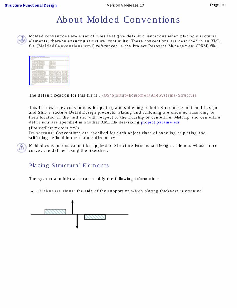
About Molded Conventions
Molded conventions are a set of rules that give default orientations when placing structural elements, thereby ensuring structural continuity. These conventions are described in an XML file (MoldedConventions.xml) referenced in the Project Resource Management (PRM) file.
The default location for this file is ../OS/Startup/EqiupmentAndSystems/Structure
This file describes conventions for plating and stiffening of both Structure Functional Design and Ship Structure Detail Design products. Plating and stiffening are oriented according to their location in the hull and with respect to the midship or centerline. Midship and centerline definitions are specified in another XML file describing project parameters (ProjectParameters.xml). Important: Conventions are specified for each object class of paneling or plating and stiffening defined in the feature dictionary.
Molded conventions cannot be applied to Structure Functional Design stiffeners whose trace curves are defined using the Sketcher.
Placing Structural Elements
The system administrator can modify the following information:
● ThicknessOrient: the side of the support on which plating thickness is oriented
161Page Structure Functional Design Version 5 Release 13

● WebSideOrient: the side of the plating on which the stiffener is placed
● FlangeOrient: orientation of the stiffener flange
● AnchorPoint: the point at which the stiffener section is anchored along its trace.
The default value is WSL (web side left).
Symbols Used
The following letters are used to describe how structural elements are placed:
● P: in the positive direction of one of the main ship directions, regardless of the midship or centerline
● M: in the negative direction of one of the main ship directions, regardless of the midship or centerline
● I: towards the midship or centerline
● O: away from the midship or centerline
162Page Structure Functional Design Version 5 Release 13

Do not change names of feature dictionary classes.
163Page Structure Functional Design Version 5 Release 13
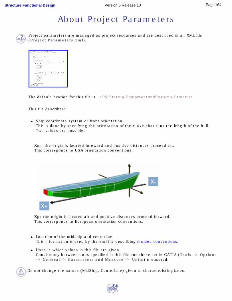
About Project Parameters
Project parameters are managed as project resources and are described in an XML file (Project Parameters.xml).
The default location for this file is ../OS/Startup/EqiupmentAndSystems/Structure
This file describes:
● Ship coordinate system or front orientation.This is done by specifying the orientation of the x-axis that runs the length of the hull. Two values are possible:
Xm: the origin is located foreward and positive distances proceed aft. This corresponds to USA orientation conventions.
Xp: the origin is located aft and positive distances proceed forward. This corresponds to European orientation conventions.
● Location of the midship and centerline.
This information is used by the xml file describing molded conventions.
● Units in which values in this file are given.Consistency between units specified in this file and those set in CATIA (Tools -> Options -> General -> Parameters and Measure -> Units) is ensured.
Do not change the names (MidShip, CenterLine) given to characteristic planes.
164Page Structure Functional Design Version 5 Release 13

Knowledgeware CapabilitiesStructure Functional Design Package in Knowledge Expert
Design RulesUsing Checks to Position Openings
165Page Structure Functional Design Version 5 Release 13
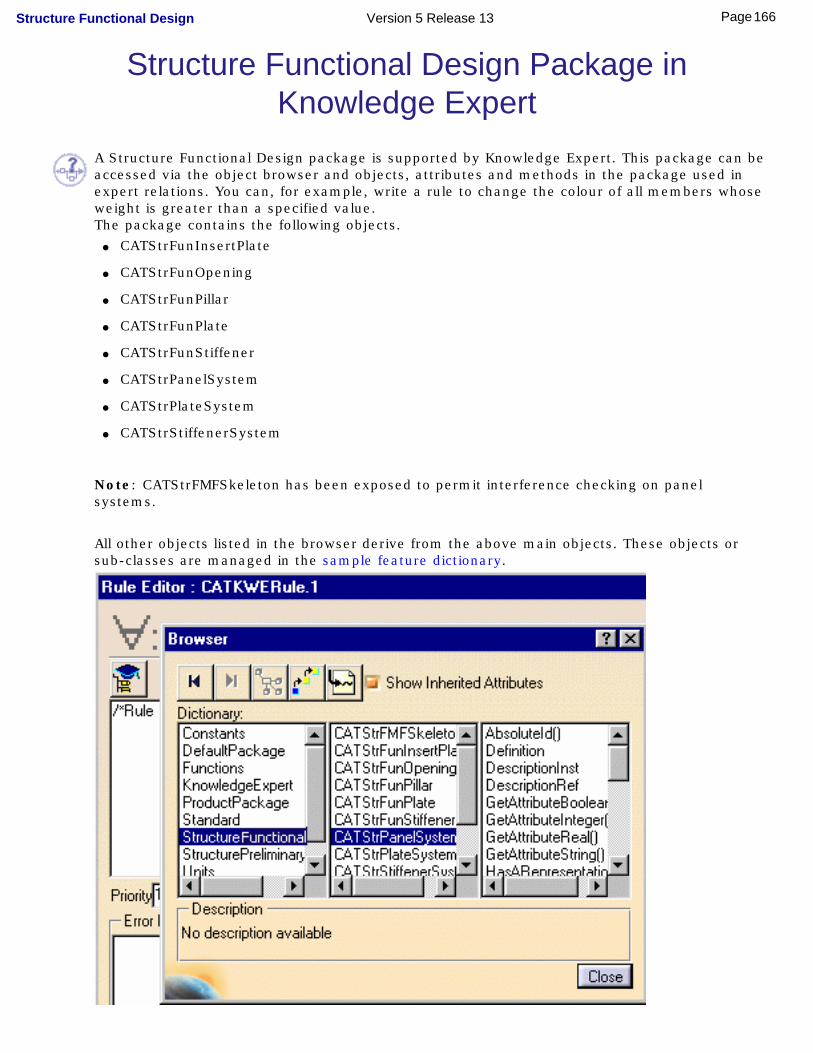
Structure Functional Design Package in Knowledge Expert
A Structure Functional Design package is supported by Knowledge Expert. This package can be accessed via the object browser and objects, attributes and methods in the package used in expert relations. You can, for example, write a rule to change the colour of all members whose weight is greater than a specified value.The package contains the following objects.
● CATStrFunInsertPlate
● CATStrFunOpening
● CATStrFunPillar
● CATStrFunPlate
● CATStrFunStiffener
● CATStrPanelSystem
● CATStrPlateSystem
● CATStrStiffenerSystem
Note: CATStrFMFSkeleton has been exposed to permit interference checking on panel systems.
All other objects listed in the browser derive from the above main objects. These objects or sub-classes are managed in the sample feature dictionary.
166Page Structure Functional Design Version 5 Release 13

For information on object attributes and methods, see Structure Functional Design in the Reference Information section of the Knowledge Expert User's Guide.
167Page Structure Functional Design Version 5 Release 13
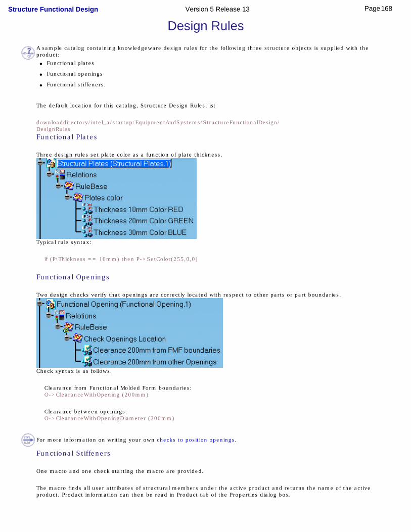
Design RulesA sample catalog containing knowledgeware design rules for the following three structure objects is supplied with the product:
● Functional plates
● Functional openings
● Functional stiffeners.
The default location for this catalog, Structure Design Rules, is:
downloaddirectory/intel_a/startup/EquipmentAndSystems/StructureFunctionalDesign/DesignRulesFunctional Plates
Three design rules set plate color as a function of plate thickness.
Typical rule syntax:
if (P\Thickness == 10mm) then P->SetColor(255,0,0)
Functional Openings
Two design checks verify that openings are correctly located with respect to other parts or part boundaries.
Check syntax is as follows.
Clearance from Functional Molded Form boundaries:O->ClearanceWithOpening (200mm)
Clearance between openings:O->ClearanceWithOpeningDiameter (200mm)
For more information on writing your own checks to position openings.
Functional Stiffeners
One macro and one check starting the macro are provided.
The macro finds all user attributes of structural members under the active product and returns the name of the active product. Product information can then be read in Product tab of the Properties dialog box.
168Page Structure Functional Design Version 5 Release 13

Check syntax is:
LaunchMacroFromDoc ("ProductionInformation.CATScript")
The default location for the macro ProductionInformation.CATScript is:
downloaddirectory/intel_a/code/command
Sample macro:'// COPYRIGHT DASSAULT SYSTEMES 1999'//============================================================================'//'// Language="VBSCRIPT"'// Sample of macro to add and valuate attribute for data extraction'//'//============================================================================'// It is advised that the user understand the VBScript and VBA concepts before'// attempting to modify the code to suit their needs. Microsoft Excel 97'// provides excellent documentation on the use of VBScript and VBA.'// '// '//============================================================================
dim workbooks as AnyObjectdim workbook as AnyObjectdim strWB as Workbenchdim strServ as AnyObject
'//---------------------------------------------------------------------------'// User customization of the attributes which will be added or valuated'// tabAttribute is an array which defines the name of the attributes'// typAttribute is an array which defines the type of the attributes'// In this sample we provide 4 types but many others are available'// cf Knowledgeware automation guide'//---------------------------------------------------------------------------dim nbAttributes as integernbAttributes = 4dim tabAttributes(4)dim typAttributes(4)
tabAttributes(1) = "DataString"tabAttributes(2) = "DataReal"tabAttributes(3) = "DataInteger"tabAttributes(4) = "DataLength"
typAttributes(1) = "String"typAttributes(2) = "Real"typAttributes(3) = "Integer"typAttributes(4) = "Length"
'//---------------------------------------------------------------------------'// Create parameters value'//---------------------------------------------------------------------------Sub CreateParameters(iProduct)
On Error Resume Next
dim parameters as Parametersdim userParameters as Parametersdim param as Parameter
169Page Structure Functional Design Version 5 Release 13

dim paramName as string
set parameters = iProduct.ReferenceProduct.Parametersset userParameters = iProduct.ReferenceProduct.UserRefProperties
dim nbParameters As IntegernbParameters = RefParameters.Count
dim sInstanceName As Stringdim sPartNumber As StringsInstanceName = iProduct.NamesPartNumber = iProduct.ReferenceProduct.Name
Set relations1 = iProduct.ReferenceProduct.Relations
Err.Clear
Dim member as StrMemberDim members as StrMembersSet members = iProduct.Parent.Parent.GetTechnologicalObject("StructureMembers")if (Not(members Is Nothing)) thenset member = members.Item(sInstanceName)if (Err.Number <> 0) thenset member = Nothingend ifend if
Err.Clear
if (member Is Nothing) thenDim plate As StrPlate Dim plates as StrPlates Set plates = iProduct.Parent.Parent.GetTechnologicalObject("StructurePlates")if (Not(plates Is Nothing)) thenset plate = plates.Item(sInstanceName)if (Err.Number <> 0) thenset plate = Nothingend ifend ifend if
dim lfound as Booleandim i As Integerif (nbAttributes > 0 AND (Not(member Is Nothing) OR Not(plate Is Nothing))) thenfor i = 1 to nbAttributes
Err.Clear
paramName = sPartNumber & "\Properties\" & tabAttributes(i)
'// We find if the attribute already existlfound = falsefor j = 1 To userParameters.Countif (userParameters.Item(j).Name = paramName) thenset param = userParameters.Item(j)lfound = trueend ifnext
if (lfound = true) then'// Update of the attribute value if needed'// In this sample we modify the value using param.Valueif (typAttributes(i) = "String") thenElseif (typAttributes(i) = "Length") thenparam.Value = 200Elseif (typAttributes(i) = "Real") thenparam.Value = 400.0Elseif (typAttributes(i) = "Integer") thenparam.Value = 50end ifelse'// Creation of the attributes according to its type'// If you need to create other type of attribute'// you can use the mode Record to record a macro interactively and edit it to see the'// synthax to be used.
170Page Structure Functional Design Version 5 Release 13
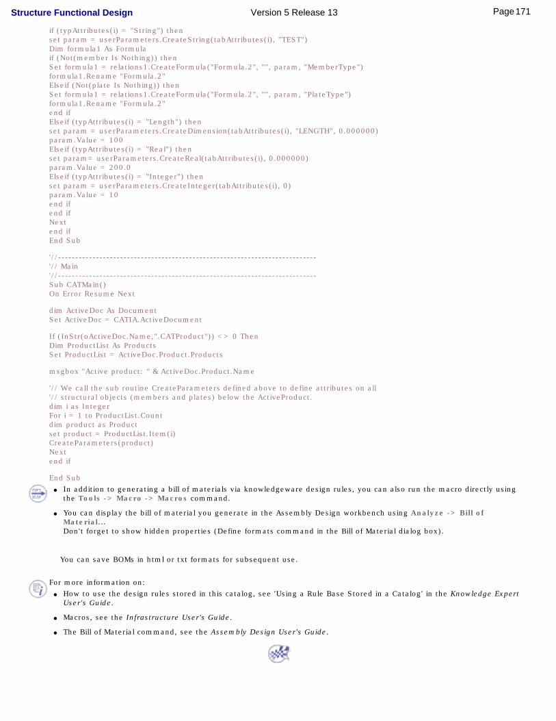
if (typAttributes(i) = "String") thenset param = userParameters.CreateString(tabAttributes(i), "TEST")Dim formula1 As Formulaif (Not(member Is Nothing)) thenSet formula1 = relations1.CreateFormula("Formula.2", "", param, "MemberType")formula1.Rename "Formula.2"Elseif (Not(plate Is Nothing)) thenSet formula1 = relations1.CreateFormula("Formula.2", "", param, "PlateType")formula1.Rename "Formula.2"end ifElseif (typAttributes(i) = "Length") thenset param = userParameters.CreateDimension(tabAttributes(i), "LENGTH", 0.000000)param.Value = 100Elseif (typAttributes(i) = "Real") thenset param= userParameters.CreateReal(tabAttributes(i), 0.000000)param.Value = 200.0Elseif (typAttributes(i) = "Integer") thenset param = userParameters.CreateInteger(tabAttributes(i), 0)param.Value = 10end ifend ifNextend ifEnd Sub
'//---------------------------------------------------------------------------'// Main'//---------------------------------------------------------------------------Sub CATMain()On Error Resume Next
dim ActiveDoc As DocumentSet ActiveDoc = CATIA.ActiveDocument
If (InStr(oActiveDoc.Name,".CATProduct")) <> 0 ThenDim ProductList As ProductsSet ProductList = ActiveDoc.Product.Products
msgbox "Active product: " & ActiveDoc.Product.Name
'// We call the sub routine CreateParameters defined above to define attributes on all'// structural objects (members and plates) below the ActiveProduct.dim i as Integer For i = 1 to ProductList.Countdim product as Productset product = ProductList.Item(i)CreateParameters(product)Nextend if
End Sub ● In addition to generating a bill of materials via knowledgeware design rules, you can also run the macro directly using
the Tools -> Macro -> Macros command.
● You can display the bill of material you generate in the Assembly Design workbench using Analyze -> Bill of Material... Don't forget to show hidden properties (Define formats command in the Bill of Material dialog box).
You can save BOMs in html or txt formats for subsequent use.
For more information on: ● How to use the design rules stored in this catalog, see 'Using a Rule Base Stored in a Catalog' in the Knowledge Expert
User's Guide.
● Macros, see the Infrastructure User's Guide.
● The Bill of Material command, see the Assembly Design User's Guide.
171Page Structure Functional Design Version 5 Release 13

Using Checks to Position OpeningsYou can use expert checks to verify that openings are correctly located with respect to other parts or part boundaries. You can, in this way, write checks to detect whether or not a given minimum distance is respected between:
● an opening and a panel system boundary
● the contours of two openings. Distance can be defined as a function of hole diameter
● an opening and a stiffener. Distance can be defined as a function of stiffener height or length.
● as well as checks detecting whether or not openings are centered on functional plate limits.
These checks use CATStrFunOpening in the Structure knowledge package.
Two sample checks are supplied in the design rule catalog.
You require the appropriate knowledgeware license.
No sample document is supplied.
This task shows you how to create a check to verify whether or not openings respect a minimum distance of 100mm.
Writing the Expert Check
Before you begin, make sure you have selected the required package.1. To customize Knowledgeware settings:
● Select Tools -> Options, General -> Parameters and Measure
● Click the Knowledge tab
● Check the load extended language libraries option
● Load the Structure package
172Page Structure Functional Design Version 5 Release 13

2. To customize Product Structure settings: ● Check the Infrastructure category, then the Product Structure sub-category, and click
the Tree Customization tab
● Set both Parameters and Relations options to Yes
You are now ready to write your check.
3. Select Knowledgeware -> Knowledge Expert from the Start menu to switch to the Knowledge Expert workbench.
4 Select the RuleBase relation in the specification tree, then click the Expert Check icon.
The Check Editor dialog box appears.
173Page Structure Functional Design Version 5 Release 13
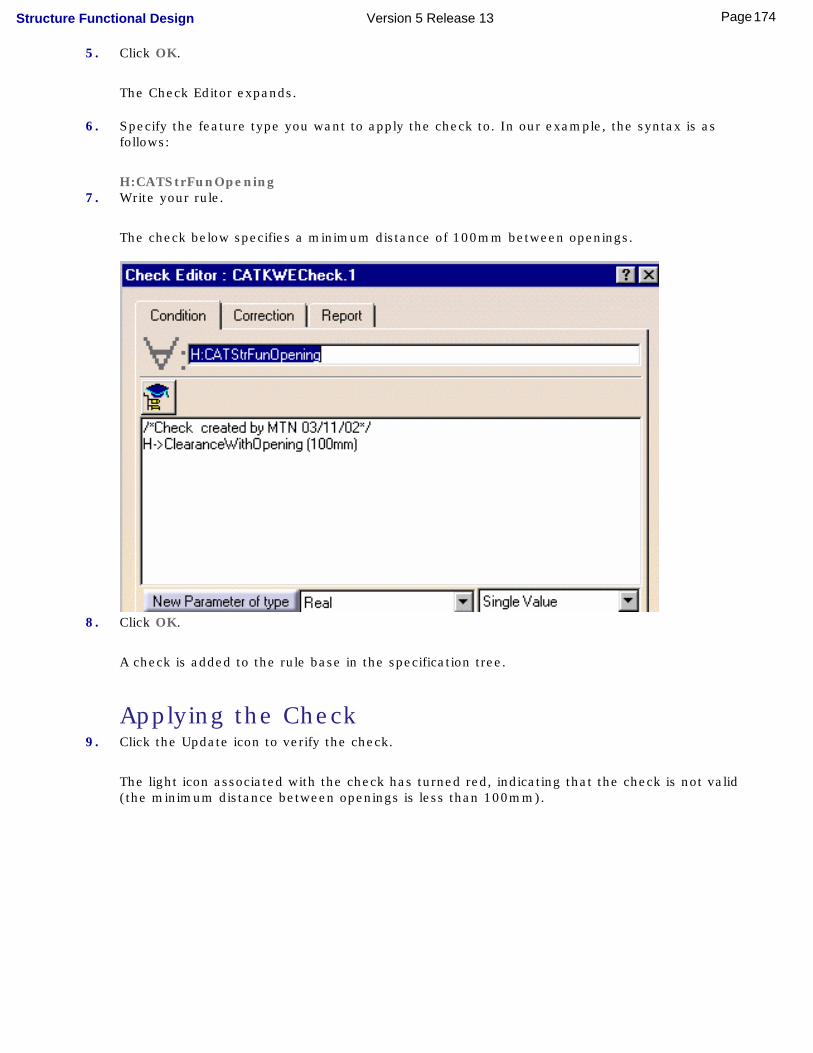
5. Click OK.
The Check Editor expands.
6. Specify the feature type you want to apply the check to. In our example, the syntax is as follows:
H:CATStrFunOpening7. Write your rule.
The check below specifies a minimum distance of 100mm between openings.
8. Click OK.
A check is added to the rule base in the specification tree.
Applying the Check9. Click the Update icon to verify the check.
The light icon associated with the check has turned red, indicating that the check is not valid (the minimum distance between openings is less than 100mm).
174Page Structure Functional Design Version 5 Release 13
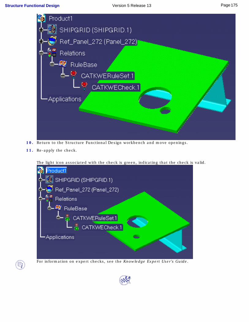
10. Return to the Structure Functional Design workbench and move openings.
11. Re-apply the check.
The light icon associated with the check is green, indicating that the check is valid.
For information on expert checks, see the Knowledge Expert User's Guide.
175Page Structure Functional Design Version 5 Release 13

Integration with ENOVIA LCAWorking with ENOVIA LCA: Optimal CATIA PLM Usability
Working with Catalogs in ENOVIA LCA
176Page Structure Functional Design Version 5 Release 13
Working with ENOVIA LCA: Optimal CATIA PLM Usability
When working with ENOVIA LCA, a new mode ensures that you only create data in CATIA that can be correctly saved in ENOVIA.
ENOVIA LCA offers two different storage modes: Workpackage (Document kept - Publications Exposed) and Explode (Document not kept). Both Structure Functional Design (SFD) and Ship Structure Detail Design (SDD) have been configured to work in the Workpackage mode.
Structure Functional Design
The Structure Functional Design workbench is set up such that the user cannot create functional objects without first creating a panel system. When first entering the workbench, all other commands are therefore unavailable. The panel system has been defined as an ENOVIA LCA workpackage.
Ship Structure Detail Design
In Ship Structure Functional Design, the block scheme and paneling system have been defined as ENOVIA LCA workpackages.
The safe save mode means that certain commands (Automatic Connection, Manual Connection, Connetion Body and Mitering) are unavailable (i.e. grayed). You cannot make connections or miter cuts between two different workpackages. Recommendation: Open the paneling system in a new window and create connections within the same workpackage.
SR1 commands -> Warning dialog box !!!!
Recommended Methodology
The recommended methodology for working with ENOVIA LCA is:
● Send your ENOVIA document to CATIA.
● Work on your design in CATIA, whether from scratch or modifying an existing design.
● Save your CATIA data in ENOVIA.
To ensure seamless integration, you must have both a CATIA and ENOVIA session running.
1. In the Product Structure workbench of CATIA V5, click the Init Enovia V5 Connection... icon to establish the connection
between CATIA V5 and ENOVIA LCA.
2. In ENOVIA LCA, send your ENOVIA document to CATIA.
3. Work on your design in your CATIA V5 application.
4. In the Product Structure workbench of CATIA V5, click the Save Data in ENOVIA V5 Server... icon to save your CATIA
data in ENOVIA.
The Save in ENOVIA V5 dialog box appears showing objects to be saved and set to the correct save mode and save options.
The dialog box below shows Structure Functional Design objects.
5. Simply click OK in the dialog box.
177Page Structure Functional Design Version 5 Release 13

For more information, see the CATIA / ENOVIA Interoperability User's Guide.
In ENOVIA LCA, the SFD panel system, and SDD block scheme and paneling system are each saved as one document.
178Page Structure Functional Design Version 5 Release 13
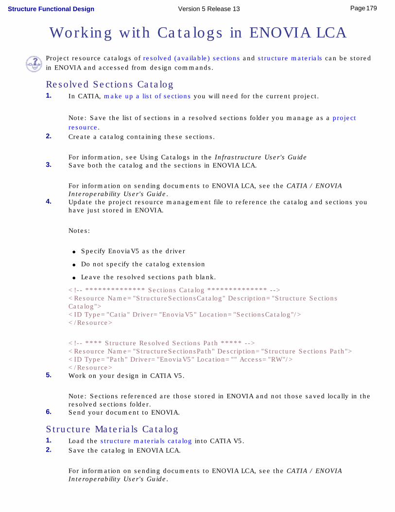
Working with Catalogs in ENOVIA LCAProject resource catalogs of resolved (available) sections and structure materials can be stored in ENOVIA and accessed from design commands.
Resolved Sections Catalog 1. In CATIA, make up a list of sections you will need for the current project.
Note: Save the list of sections in a resolved sections folder you manage as a project resource.
2. Create a catalog containing these sections.
For information, see Using Catalogs in the Infrastructure User's Guide 3. Save both the catalog and the sections in ENOVIA LCA.
For information on sending documents to ENOVIA LCA, see the CATIA / ENOVIA Interoperability User's Guide.
4. Update the project resource management file to reference the catalog and sections you have just stored in ENOVIA.
Notes:
● Specify EnoviaV5 as the driver
● Do not specify the catalog extension
● Leave the resolved sections path blank.
<!-- ************** Sections Catalog ************** --><Resource Name="StructureSectionsCatalog" Description="Structure Sections Catalog"> <ID Type="Catia" Driver="EnoviaV5" Location="SectionsCatalog"/></Resource>
<!-- **** Structure Resolved Sections Path ***** --><Resource Name="StructureSectionsPath" Description="Structure Sections Path"><ID Type="Path" Driver="EnoviaV5" Location="" Access="RW"/></Resource>
5. Work on your design in CATIA V5.
Note: Sections referenced are those stored in ENOVIA and not those saved locally in the resolved sections folder.
6. Send your document to ENOVIA.
Structure Materials Catalog 1. Load the structure materials catalog into CATIA V5. 2. Save the catalog in ENOVIA LCA.
For information on sending documents to ENOVIA LCA, see the CATIA / ENOVIA Interoperability User's Guide.
179Page Structure Functional Design Version 5 Release 13
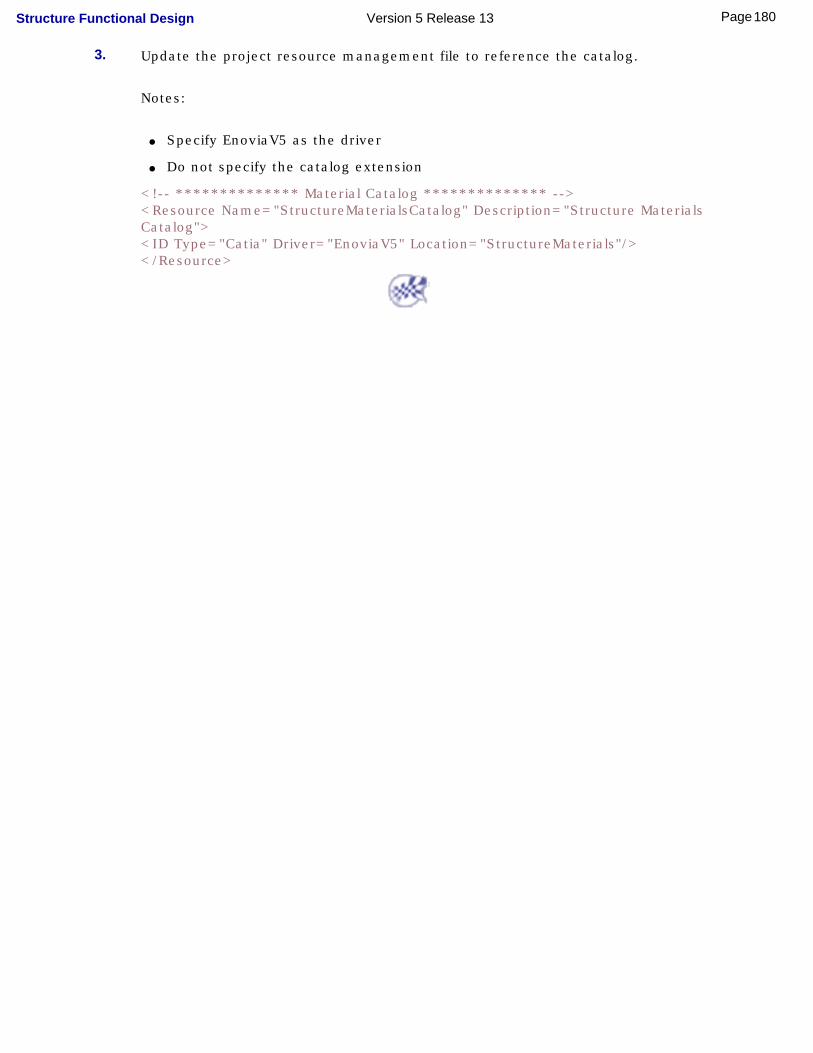
3. Update the project resource management file to reference the catalog.
Notes:
● Specify EnoviaV5 as the driver
● Do not specify the catalog extension
<!-- ************** Material Catalog ************** --><Resource Name="StructureMaterialsCatalog" Description="Structure Materials Catalog"> <ID Type="Catia" Driver="EnoviaV5" Location="StructureMaterials"/></Resource>
180Page Structure Functional Design Version 5 Release 13
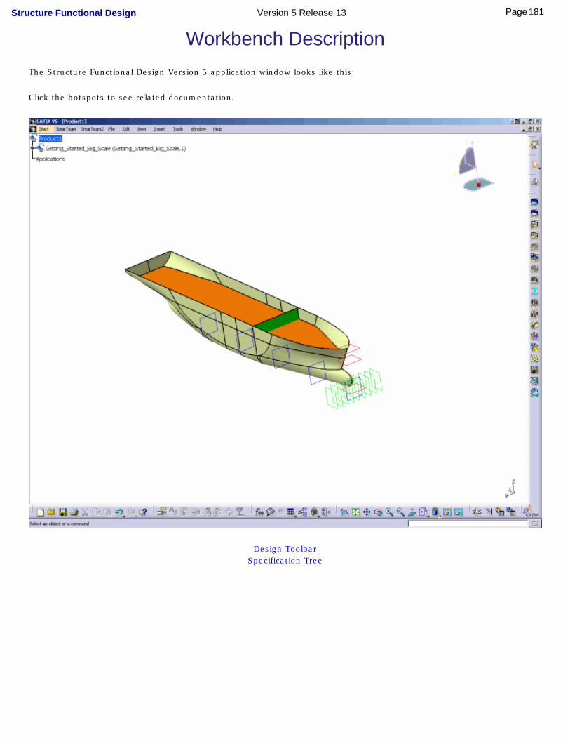
Workbench DescriptionThe Structure Functional Design Version 5 application window looks like this:
Click the hotspots to see related documentation.
Design ToolbarSpecification Tree
181Page Structure Functional Design Version 5 Release 13

Design Toolbar
See Creating a panel system
See Creating panel sub-systems
See Openings
See Adding a plate system feature
See Insert plates
See Straking
See Creating functional plates
See Add a stiffener system feature
See Making up a list of sections
See Creating stiffeners
See Creating pillars
See Creating twisted stiffeners
See Shell expansion (Shell Expansion command)
See Shell expansion (Import Shell Expansion command)
See Defining shell spline traces
See Exporting wireframe skeletons
See Splitting plates & shapes
See Merging plates & shapes
182Page Structure Functional Design Version 5 Release 13

Specification Tree
Icons displayed in the specification tree and specific to the Structure Functional Design workbench identify:
Panel systems and panel sub-systems
Openings
Plate systems
Functional plates and insert plates
Stiffener systems
Stiffeners, twisted profiles and pillars
For other symbols used in the specification tree, see Specification Tree Symbols.
183Page Structure Functional Design Version 5 Release 13

Customizing Structure Functional DesignBefore you start your first session, you can customize the way you work to suit your habits. This type of customization is stored in permanent setting files: these settings will not be lost if you end your session.
1. Select the Tools -> Options command.
The Options dialog box displays.
2. Select the Equipment & Systems category in the left-hand box.
3. Click the Structure Functional Design sub-category.
The Catalogs and Design tabs display.
❍ The Catalogs tab lets you identify the path to the resolved sections folder.
❍ The Design tab lets you define default colors and a default material-grade combination.
4. Set options in these tabs according to your needs.
5. Click OK in the Options dialog box when done.
184Page Structure Functional Design Version 5 Release 13
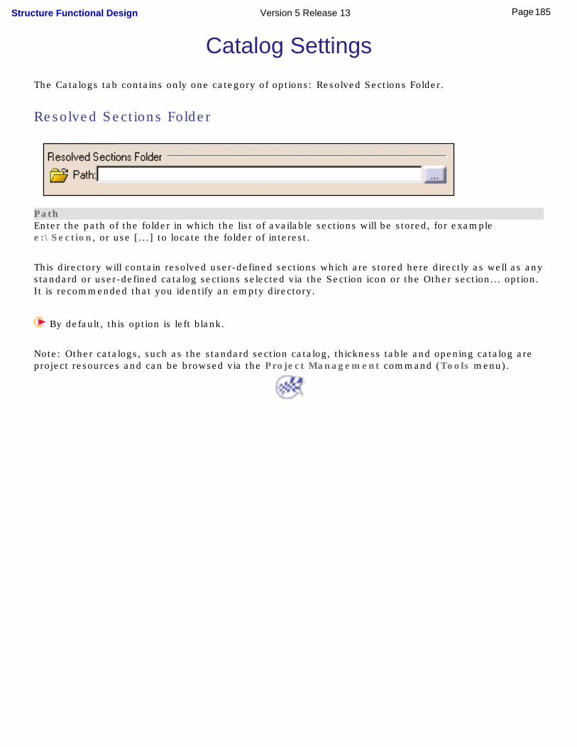
Catalog SettingsThe Catalogs tab contains only one category of options: Resolved Sections Folder.
Resolved Sections Folder
PathEnter the path of the folder in which the list of available sections will be stored, for example e:\Section, or use [...] to locate the folder of interest.
This directory will contain resolved user-defined sections which are stored here directly as well as any standard or user-defined catalog sections selected via the Section icon or the Other section... option. It is recommended that you identify an empty directory.
By default, this option is left blank.
Note: Other catalogs, such as the standard section catalog, thickness table and opening catalog are project resources and can be browsed via the Project Management command (Tools menu).
185Page Structure Functional Design Version 5 Release 13
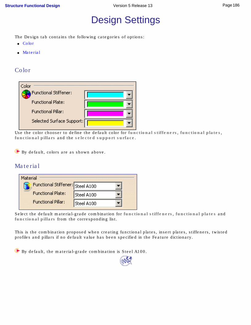
Design SettingsThe Design tab contains the following categories of options:
● Color
● Material
Color
Use the color chooser to define the default color for functional stiffeners, functional plates, functional pillars and the selected support surface.
By default, colors are as shown above.
Material
Select the default material-grade combination for functional stiffeners, functional plates and functional pillars from the corresponding list.
This is the combination proposed when creating functional plates, insert plates, stiffeners, twisted profiles and pillars if no default value has been specified in the Feature dictionary.
By default, the material-grade combination is Steel A100.
186Page Structure Functional Design Version 5 Release 13
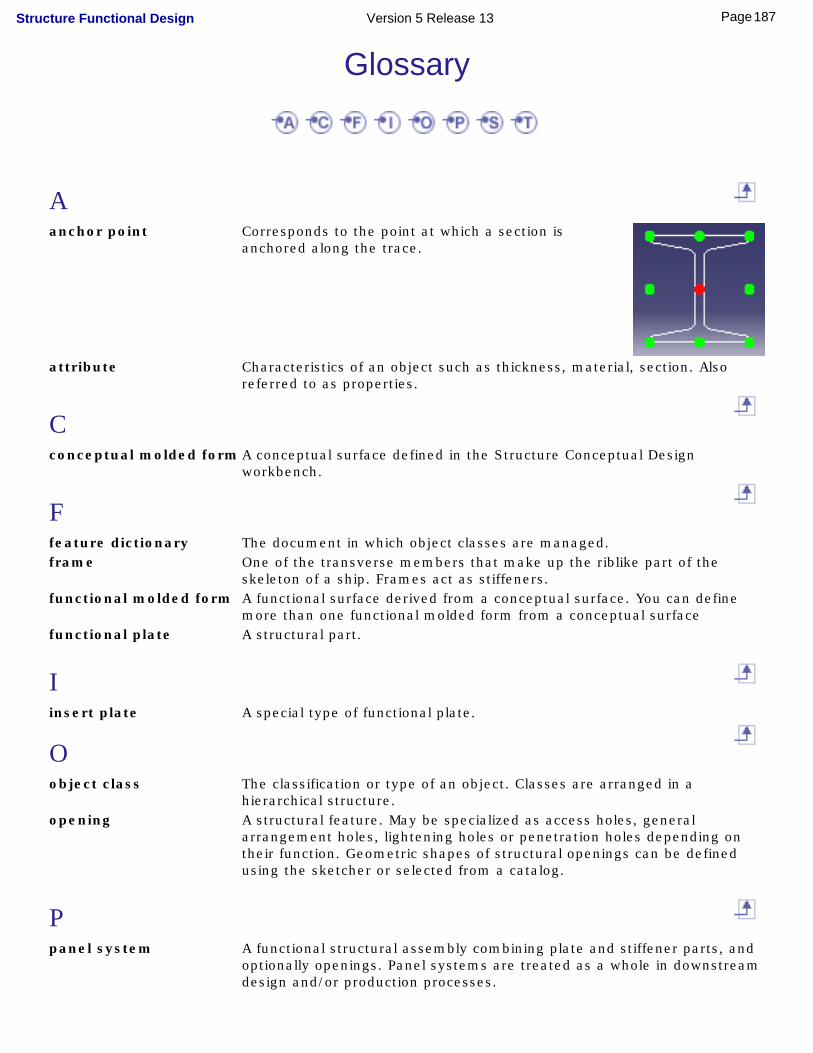
Glossary
Aanchor point Corresponds to the point at which a section is
anchored along the trace.
attribute Characteristics of an object such as thickness, material, section. Also referred to as properties.
Cconceptual molded form A conceptual surface defined in the Structure Conceptual Design
workbench.
Ffeature dictionary The document in which object classes are managed.frame One of the transverse members that make up the riblike part of the
skeleton of a ship. Frames act as stiffeners.functional molded form A functional surface derived from a conceptual surface. You can define
more than one functional molded form from a conceptual surfacefunctional plate A structural part.
Iinsert plate A special type of functional plate.
Oobject class The classification or type of an object. Classes are arranged in a
hierarchical structure.opening A structural feature. May be specialized as access holes, general
arrangement holes, lightening holes or penetration holes depending on their function. Geometric shapes of structural openings can be defined using the sketcher or selected from a catalog.
Ppanel system A functional structural assembly combining plate and stiffener parts, and
optionally openings. Panel systems are treated as a whole in downstream design and/or production processes.
187Page Structure Functional Design Version 5 Release 13
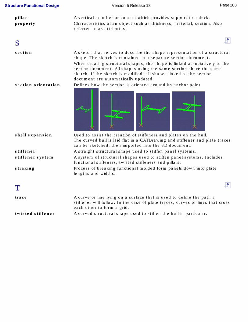
pillar A vertical member or column which provides support to a deck.property Characteristics of an object such as thickness, material, section. Also
referred to as attributes.
Ssection A sketch that serves to describe the shape representation of a structural
shape. The sketch is contained in a separate section document. When creating structural shapes, the shape is linked associatively to the
section document. All shapes using the same section share the same sketch. If the sketch is modified, all shapes linked to the section document are automatically updated.
section orientation Defines how the section is oriented around its anchor point
shell expansion Used to assist the creation of stiffeners and plates on the hull.
The curved hull is laid flat in a CATDrawing and stiffener and plate traces can be sketched, then imported into the 3D document.
stiffener A straight structural shape used to stiffen panel systems.stiffener system A system of structural shapes used to stiffen panel systems. Includes
functional stiffeners, twisted stiffeners and pillars.straking Process of breaking functional molded form panels down into plate
lengths and widths.
Ttrace A curve or line lying on a surface that is used to define the path a
stiffener will follow. In the case of plate traces, curves or lines that cross each other to form a grid.
twisted stiffener A curved structural shape used to stiffen the hull in particular.
188Page Structure Functional Design Version 5 Release 13

Index
Aadding to
user section catalogs
anchor point anchor point(s)
creating
user sections
attribute
Ccatalog settings command
Export
Functional Plate
Import Shell Expansion
Insert Plate
Merge
Opening
Panel Sub-System
Panel System
Pillar
Plane System
Plate System
Section
Shell Expansion
Shell Spline
Split
189Page Structure Functional Design Version 5 Release 13
Stiffener
Stiffener System
Straking Grid
Twisted Profile
conceptual molded form copying
systems creating
anchor point(s)
functional plate
insert plate
opening
panel sub-system
panel system
pillar
plate system
reports
stiffener
stiffener system
twisted stiffener
user section catalogs customizing
catalog settings
design settings
Ddefining
plate traces
shell traces
stiffener traces
design rules
190Page Structure Functional Design Version 5 Release 13
design settings
Eediting
functional plate
insert plate
opening
stiffener definition
stiffener traces
ENOVIA LCA integration
Export command
exporting wireframe skeleton
Ffeature dictionary
flip stiffener section
frame
functional molded form
functional plate
editing
Functional Plate command
Ggenerating
reports
191Page Structure Functional Design Version 5 Release 13

IImport Shell Expansion command
insert plate
editing
removing
Insert Plate command
insert report in drawing
Kknowledge expert knowledgeware
checks for openings
design rules
structure package
Mmaking up list of sections
Merge command merging
plate
shape modifying
merge plates and shapes
split plates and shapes
molded conventions moving
opening
192Page Structure Functional Design Version 5 Release 13
Nnaming rules
Oobject class
object naming rules
opening
editing
moving
removing
using rules
Opening command
Ppanel sub-system
Panel Sub-System command
panel system
synchronizing
Panel System command
parametric section catalogs
pillar
Pillar command
Plane System command plate
merging
splitting
plate system
adding feature
193Page Structure Functional Design Version 5 Release 13
functional plate
insert plate
plate traces
straking
Plate System command
plate traces project
creating reports
project parameters
project resource management
property
Rremoving
insert plate
opening report
define a query
define format
format
generate
reports
Ssection
making up list of
Section command
section flip
section orientation shape
194Page Structure Functional Design Version 5 Release 13
merging
splitting shell
traces
shell expansion
Shell Expansion command
Shell Spline command
shell traces
Split command splitting
plate
shape
stiffener
editing traces
flip section
traces
user sections
Stiffener command
stiffener system
adding feature
pillar
stiffener
stiffener traces
twisted stiffener
user sections
Stiffener System command
stiffener traces
straking
Straking Grid command
symmetrical systems
synchronizing panel systems systems
195Page Structure Functional Design Version 5 Release 13

mirroring
Ttrace traces
editing for stiffeners
plate
shell
stiffener
Twisted Profile command
twisted stiffener
Uuser section catalogs
adding to
creating
user sections
anchor point(s)
Wwireframe skeleton
196Page Structure Functional Design Version 5 Release 13