structural steel design-5 - al-mustansiriya university09_32_37_pm.pdf · d-20 design examples v14.2...
TRANSCRIPT

Tension Member)(
Faculty of Engineering الخامسةالمحاضرة Al-Mustansirya University
STRUCTURAL STEEL DESIGN
Tension Members -5-
Dr.Mu'taz K.M Ass. Prof. in Civil Engineering

Tension Member)(
Faculty of Engineering الخامسةالمحاضرة Al-Mustansirya University
Pin-Connected Members
Tension members connected with a single pin as diagonal bracing are subject to the failure modes covered in Section D5 of the AISC specification .There are three main failure modes that need to be checked for pin-connected members :tensile rupture on the net area , shear rupture on the effective area and bearing on the projected area of the pin as shown below :
From chapter 2 of ASCE / SEI 7 , the required tensile strength is :
1. Tensile Rupture
Pu = Ø Fu (2t.beff)
2. Shear Rupture
Pu = Ø 0.6 Fu Asf
3. Bearing
Ru = Ø 1.8 Fy Apb
4. Tensile Yielding
Pu = 0.90 Fy Ag

Tension Member)(
Faculty of Engineering الخامسةالمحاضرة Al-Mustansirya University

Tension Member)(
Faculty of Engineering الخامسةالمحاضرة Al-Mustansirya University
Dimensional requirement using AISC specification section D5.2 :
beff. = 2t + 0.63 < b
a ≥ 1.33 beff.
w ≥ 2 beff. + d
c ≥ a
D-20
Design Examples V14.2 AMERICAN INSTITUTE OF STEEL CONSTRUCTION
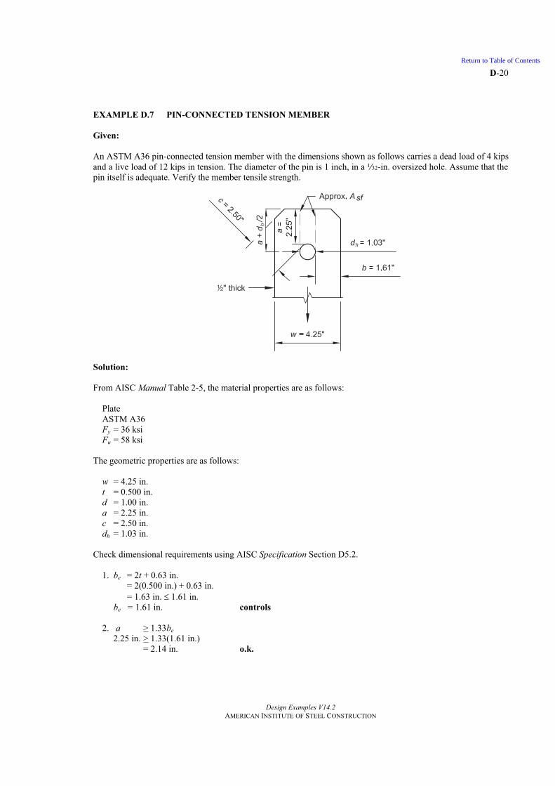
EXAMPLE D.7 PIN-CONNECTED TENSION MEMBER
Given:
An ASTM A36 pin-connected tension member with the dimensions shown as follows carries a dead load of 4 kips and a live load of 12 kips in tension. The diameter of the pin is 1 inch, in a Q-in. oversized hole. Assume that the pin itself is adequate. Verify the member tensile strength.
Solution:
From AISC Manual Table 2-5, the material properties are as follows:
PlateASTM A36 Fy = 36 ksi Fu = 58 ksi
The geometric properties are as follows:
w = 4.25 in. t = 0.500 in. d = 1.00 in. a = 2.25 in. c = 2.50 in. dh = 1.03 in.
Check dimensional requirements using AISC Specification Section D5.2.
1. be = 2t + 0.63 in. = 2(0.500 in.) + 0.63 in. = 1.63 in. 1.61 in. be = 1.61 in. controls
2. a > 1.33be 2.25 in. > 1.33(1.61 in.) = 2.14 in. o.k.
Return to Table of Contents
D-21
Design Examples V14.2 AMERICAN INSTITUTE OF STEEL CONSTRUCTION
3. w > 2be + d 4.25 in. > 2(1.61 in.) + 1.00 in. = 4.22 in. o.k.
4. c > a 2.50 in. > 2.25 in. o.k.
From Chapter 2 of ASCE/SEI 7, the required tensile strength is:
LRFD ASD Pu = 1.2(4 kips) + 1.6(12 kips) = 24.0 kips
Pa = 4 kips + 12 kips = 16.0 kips
Tensile Rupture
Calculate the available tensile rupture strength on the effective net area.
Pn = Fu(2tbe) (Spec. Eq. D5-1) = 58 ksi (2)(0.500 in.)(1.61 in.) = 93.4 kips
From AISC Specification Section D5.1, the available tensile rupture strength is:
LRFD ASD t = 0.75 tPn = 0.75(93.4 kips)
= 70.1 kips
t = 2.00 93.4 kips
2.00n
t
P
= 46.7 kips
Shear Rupture
Asf = 2t(a + d/2) = 2(0.500 in.)[2.25 in. + (1.00 in./2)]
= 2.75 in.2
Pn = 0.6FuAsf (Spec. Eq. D5-2) = 0.6(58 ksi)(2.75 in.2)
= 95.7 kips
From AISC Specification Section D5.1, the available shear rupture strength is:
LRFD ASD sf = 0.75sfPn = 0.75(95.7 kips)
= 71.8 kips
sf = 2.0095.7 kips
2.00n
sf
P
= 47.9 kips
Bearing
Apb = 0.500 in.(1.00 in.) = 0.500 in.2
Return to Table of Contents

D-22
Design Examples V14.2 AMERICAN INSTITUTE OF STEEL CONSTRUCTION
Rn = 1.8FyApb (Spec. Eq. J7-1) = 1.8(36 ksi)(0.500 in.2)
= 32.4 kips
From AISC Specification Section J7, the available bearing strength is:
LRFD ASD = 0.75 Pn = 0.75(32.4 kips)
= 24.3 kips
= 2.00 32.4 kips
2.00nP
= 16.2 kips
Tensile Yielding
Ag = wt = 4.25 in. (0.500 in.) = 2.13 in.2
Pn = FyAg (Spec. Eq. D2-1) = 36 ksi (2.13 in.2)
= 76.7 kips
From AISC Specification Section D2, the available tensile yielding strength is:
LRFD ASD t = 0.90tPn = 0.90(76.7 kips)
= 69.0 kips
t = 1.6776.7 kips
1.67n
t
P
= 45.9 kips
The available tensile strength is governed by the bearing strength limit state.
LRFD ASD Pn = 24.3 kips
24.3 kips > 24.0 kips o.k.
nP = 16.2 kips
16.2 kips > 16.0 kips o.k.
See Example J.6 for an illustration of the limit state calculations for a pin in a drilled hole.
Return to Table of Contents

Tension Member)(
Faculty of Engineering الخامسةالمحاضرة Al-Mustansirya University
Eye Bar Tension Member
An eyebar is a special type of pin‐connected member whose ends where the pin holes are located are enlarged ,as shown below .Eyebars at one time were very commonly used for the tension members for long span of bridges trusses .
Requirements using AISC Specification section D6.1 and D6-2 .
t ≥ 1/2 in
w < 8 t
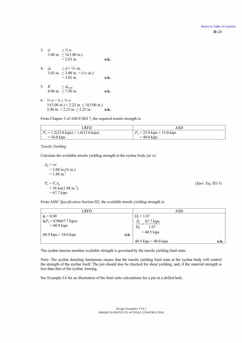
d ≥ 7/8 w
dh ≤ d + 1/32
R ≥ dhead
2/3 w ≤ b ≤ 3/4 w
AISC Specification section D2
Pu = Ø Fy Ag where Ag = w.t

D-23
Design Examples V14.2 AMERICAN INSTITUTE OF STEEL CONSTRUCTION
EXAMPLE D.8 EYEBAR TENSION MEMBER
Given:
A s-in.-thick, ASTM A36 eyebar member as shown, carries a dead load of 25 kips and a live load of 15 kips in tension. The pin diameter, d, is 3 in. Verify the member tensile strength.
Solution:
From AISC Manual Table 2-5, the material properties are as follows:
PlateASTM A36 Fy = 36 ksi Fu = 58 ksi
The geometric properties are as follows:
w = 3.00 in. b = 2.23 in. t = s in.dhead = 7.50 in. d = 3.00 in. dh = 3.03 in. R = 8.00 in.
Check dimensional requirements using AISC Specification Section D6.1 and D6.2.
1. t > 2 in. s in. > 2 in. o.k.
2. w < 8t3.00 in. < 8(s in.)
= 5.00 in. o.k.
Return to Table of Contents
D-24
Design Examples V14.2 AMERICAN INSTITUTE OF STEEL CONSTRUCTION
3. d > d w 3.00 in. > d(3.00 in.) = 2.63 in. o.k.
4. dh < d +Q in. 3.03 in. < 3.00 in. + (Q in.)
= 3.03 in. o.k.
5. R > dhead 8.00 in. > 7.50 in. o.k.
6. q w < b < w wq(3.00 in.) < 2.23 in. < w(3.00 in.)
2.00 in. < 2.23 in. < 2.25 in. o.k.
From Chapter 2 of ASCE/SEI 7, the required tensile strength is:
LRFD ASD Pu = 1.2(25.0 kips) + 1.6(15.0 kips) = 54.0 kips
Pa = 25.0 kips + 15.0 kips = 40.0 kips
Tensile Yielding
Calculate the available tensile yielding strength at the eyebar body (at w).
Ag = wt = 3.00 in.(s in.) = 1.88 in.2
Pn = FyAg (Spec. Eq. D2-1) = 36 ksi(1.88 in.2)
= 67.7 kips
From AISC Specification Section D2, the available tensile yielding strength is:
LRFD ASD t = 0.90 tPn = 0.90(67.7 kips)
= 60.9 kips
60.9 kips > 54.0 kips o.k.
t = 1.67 67.7 kips
1.67n
t
P
= 40.5 kips
40.5 kips > 40.0 kips o.k.
The eyebar tension member available strength is governed by the tensile yielding limit state.
Note: The eyebar detailing limitations ensure that the tensile yielding limit state at the eyebar body will control the strength of the eyebar itself. The pin should also be checked for shear yielding, and, if the material strength is less than that of the eyebar, bearing.
See Example J.6 for an illustration of the limit state calculations for a pin in a drilled hole.
Return to Table of Contents