structural repair manual
TRANSCRIPT
Structural Repair Manual – Xtension ENA
SERIES 400X 53‐00‐21‐350‐800 Page 201
GENERIC FUSELAGE SKIN REPAIR USING A REPAIR PATCH DOUBLER
1. General The following procedure is a generic repair for damage to the fuselage skin of Models Q400X, Damage tolerance inspection requirements are included. The intent of this procedure is to allow certain types of damage to be repaired without the need to contact Bombardier. 2. Limitations
NOTE: If damage is such that any of the criteria below cannot be met, this generic repair is not valid; contact Bombardier for an appropriate repair procedure. This repair is also not valid if there is damage to any other structural component in the area, e.g. stringers, frames, intercostals, etc.
A. The repair is applicable to fuselage skin between stations X-19.775 and X836.452 of
Models Q400X.
NOTE: This repair is not applicable to Model 400 aircraft.
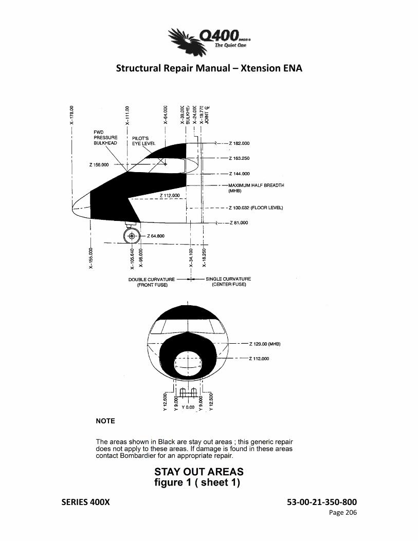
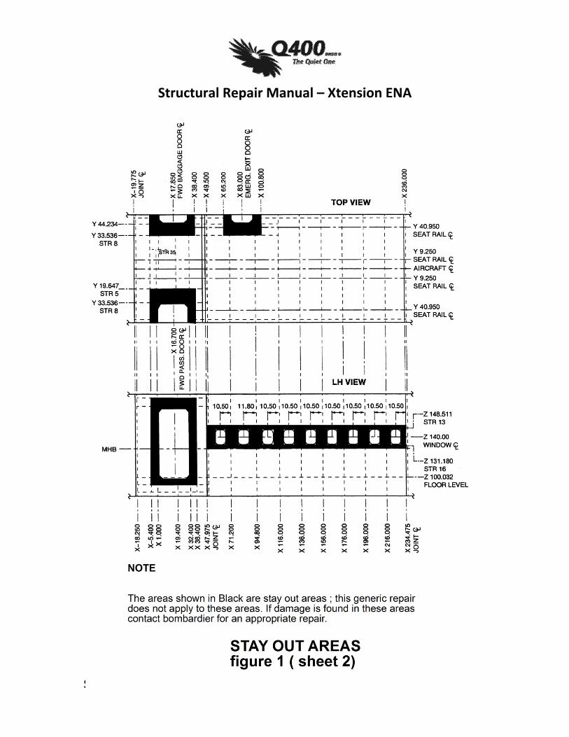
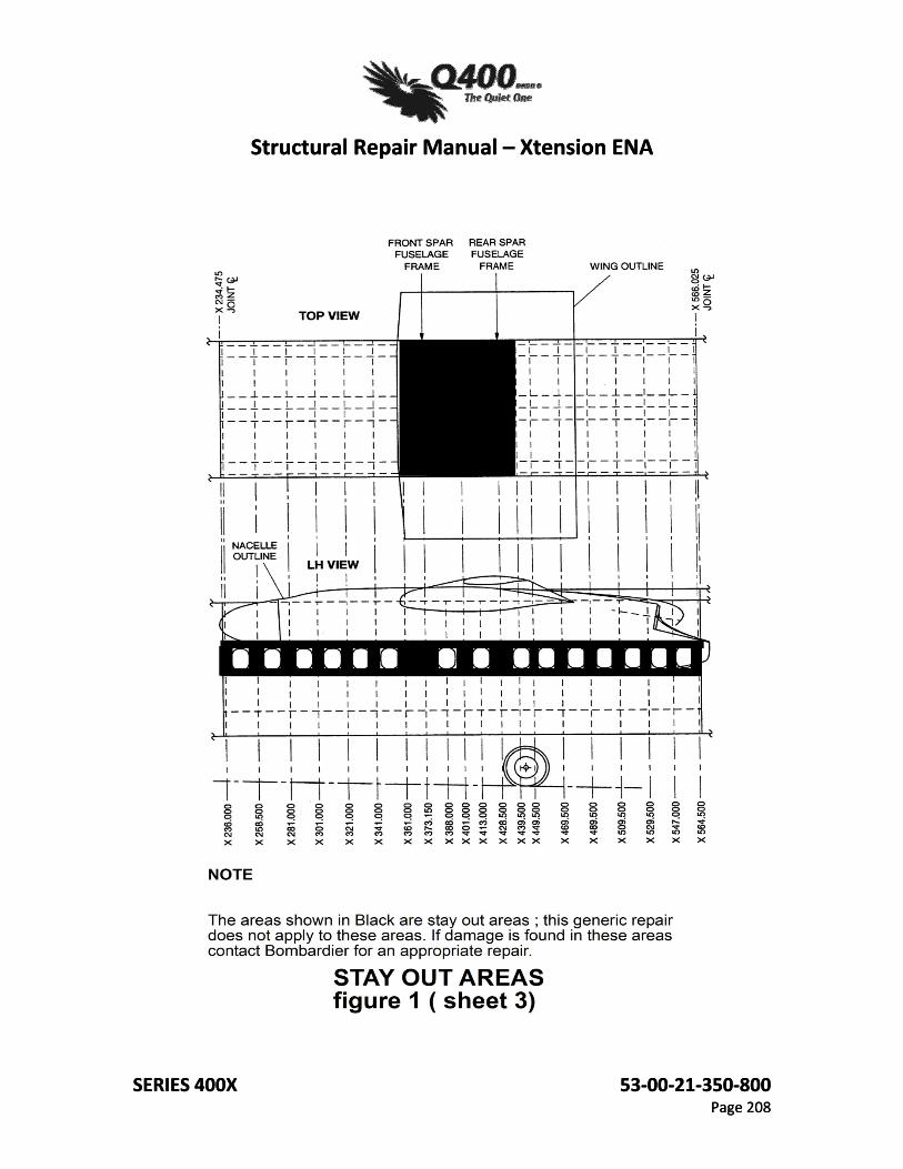
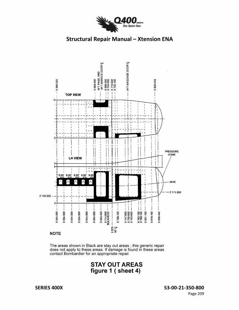
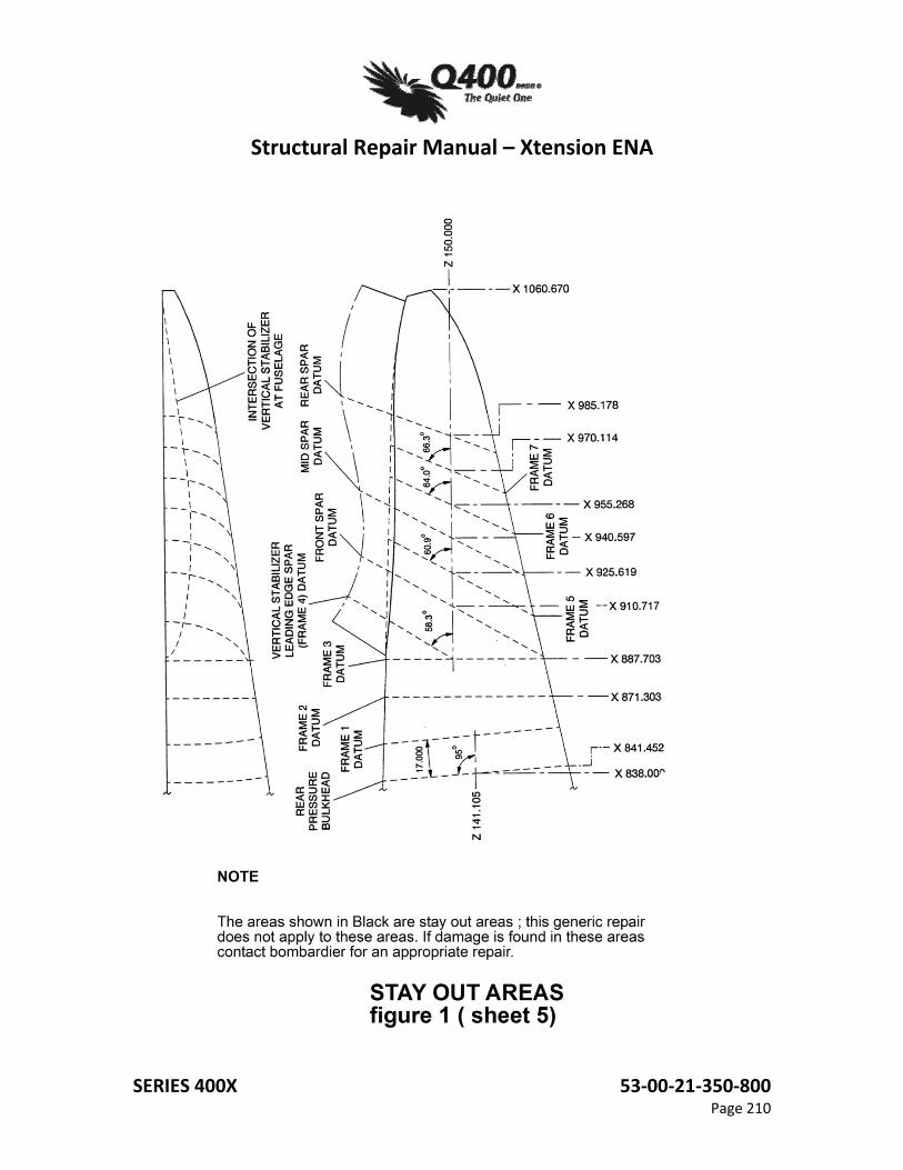
B. The repair cannot be made in any of the stay out areas shown (in black) in Figure 1, Sheet 1, 2, 3, 4 and 5.
C. The fuselage structure and repair doubler must be crack and defect free. D. A bay is defined as the skin area between two adjacent frames and two adjacent
stringers. To repair a bay using this procedure, the following conditions must be met:
(1) The bay cannot have special features such as antennas, inspection or emergency lights, drain holes, etc.
(2) The bay must have a minimum width (dimension from the rivet centerline of one frame to that of the next frame) of 7.30". (3) The repair is limited to a single bay and any adjacent bays must be free of any damage or previous repairs.
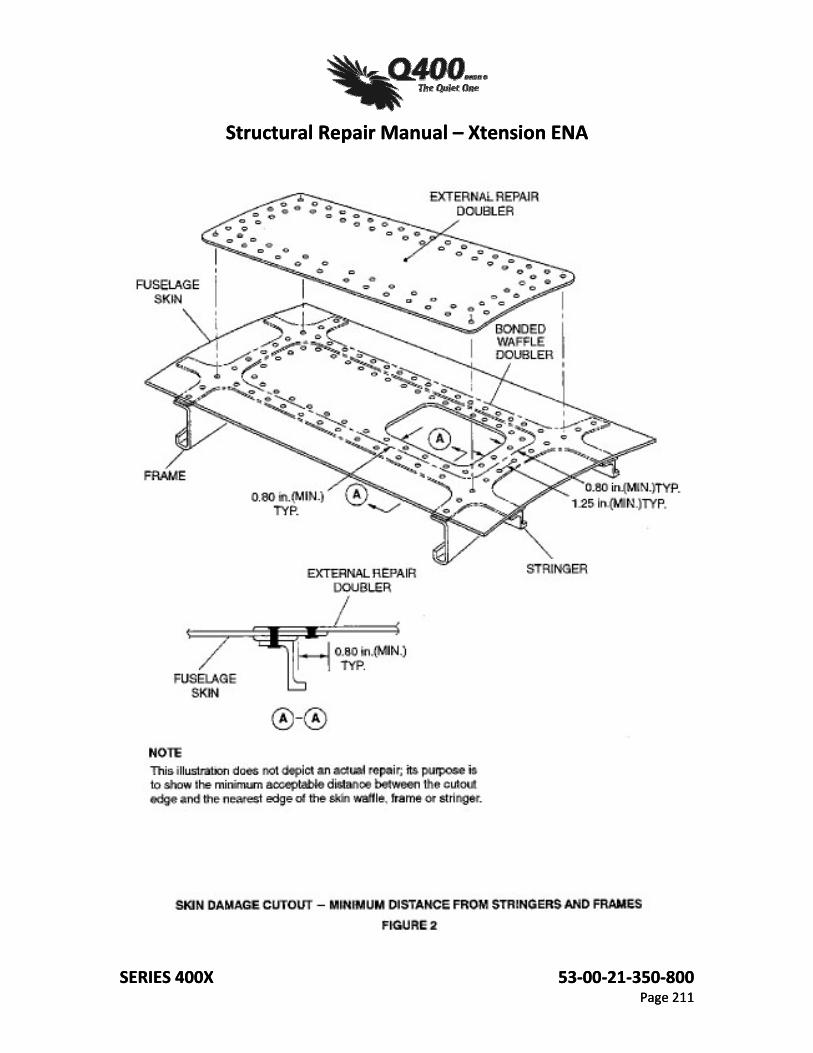
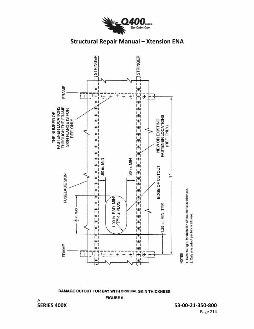
E. A cutout is defined as an area of fuselage skin that is cut from the existing structure in order to remove the damaged area. The cutout must meet the following conditions: (1) The cutout must be 0.80" minimum from the nearest stringer/frame edge and 1.25"
away from the rivet line an the frame or 0.80" away from the edge of the waffle as shown in Figure 2, page 211.
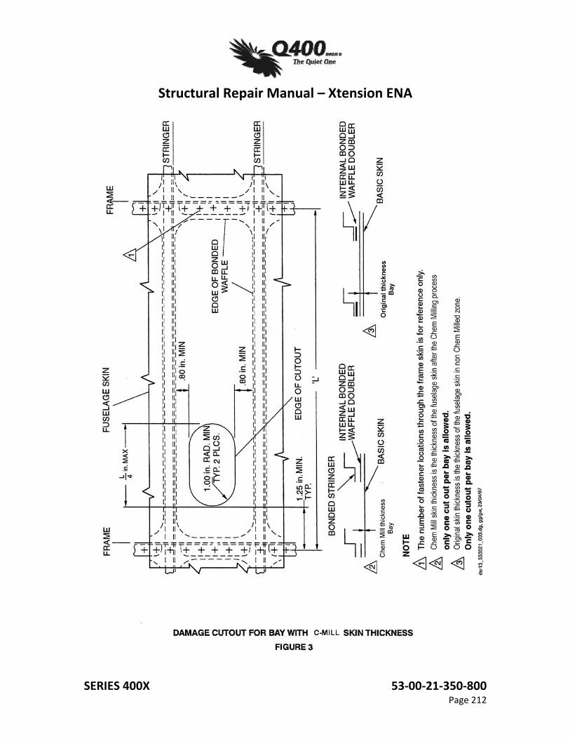
(2) The maximum allowable cutout length is L/4 inches, where L is the dimension from the rivet centerline of one frame to that of the next frame (bay width), or from the rivet centerline of one frame to the edge of the tear strap. The minimum allowable L dimension is 7.30". Any bay that is less than 7.30" wide cannot be repaired with this standard procedure.
Structural Repair Manual – Xtension ENA
SERIES 400X 53‐00‐21‐350‐800 Page 202
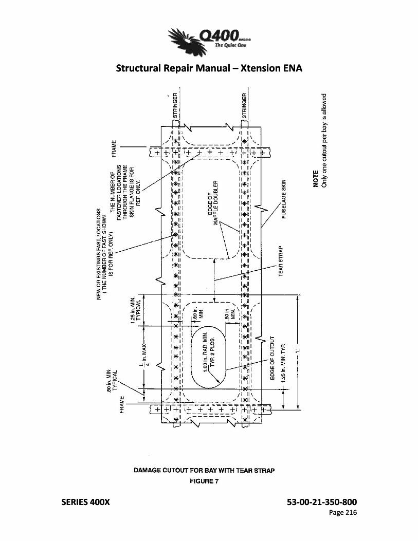
(3) The cutout radius must be a minimum of 1.00". (4) The cutout cannot go through any tear straps as defined in Figures 7 and 19.
NOTE: To ensure that a tear strap or any other structure is not inadvertently damaged, it is recommended that the cutout be made from inside the aircraft.
F. For this repair to be valid, tear straps must be completely free from any damage or previous repairs.
G. The minimum allowable length of the repair doubler is 8.00” •
3. Repair Procedure A. Repair Procedures are illustrated in Figures 3 through 20 according to the Titles listed below;
they are to be used in conjunction with the written procedures B thru H which follow.
NOTE: Definitions of Chem-Mill and Original Skin Thickness, refer to Fig 3, Page 212. (1) Bay with C-Mill Skin Thickness:
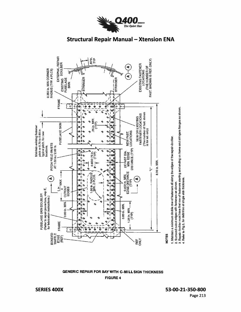
Figure 3, page 212 - Damage Cutout Procedure Figure 4, page 213 - Generic Repair Procedure
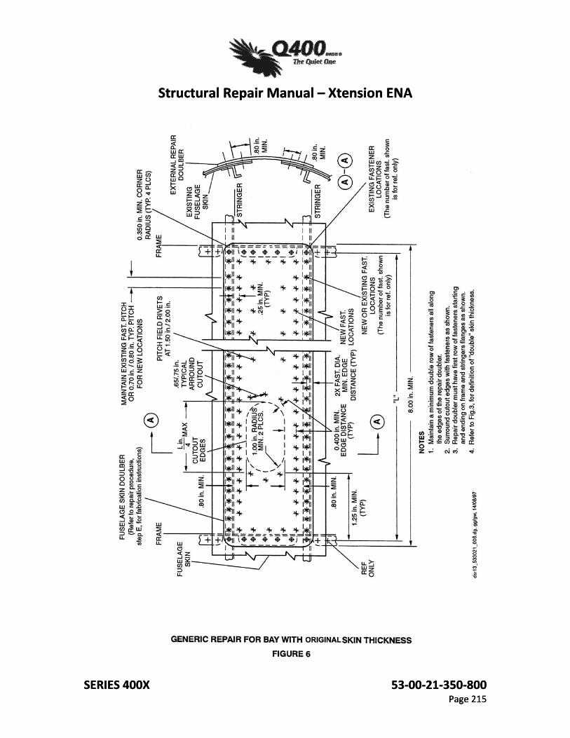
(2) Bay with Original Skin Thickness: Figure 5, page 214 - Damage Cutout Procedure Figure 6, page 215 - Generic Repair Procedure
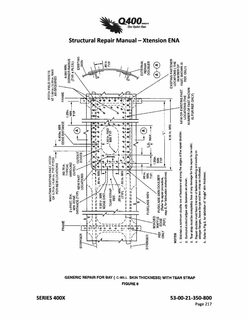
(3) Bay with Tear Strap: Figure 7, page 216 - Damage Cutout Procedure Figure 8, page 217 - Generic Repair Procedure (for Single Skin Thickness)
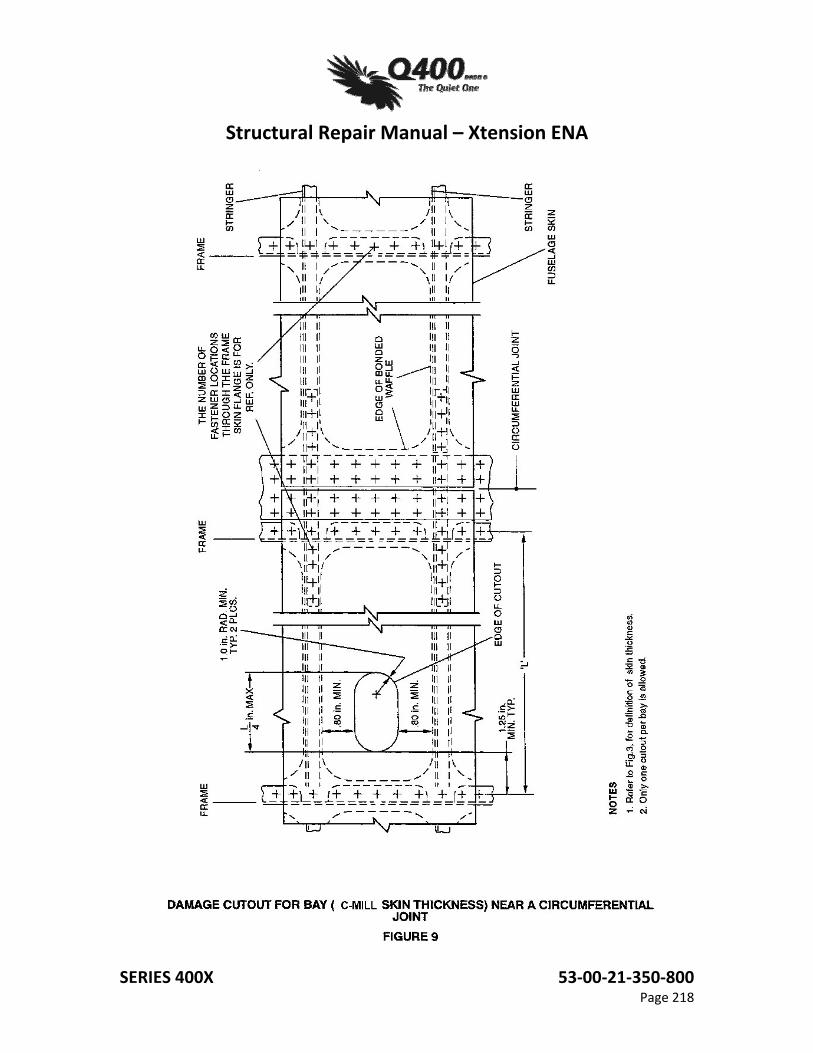
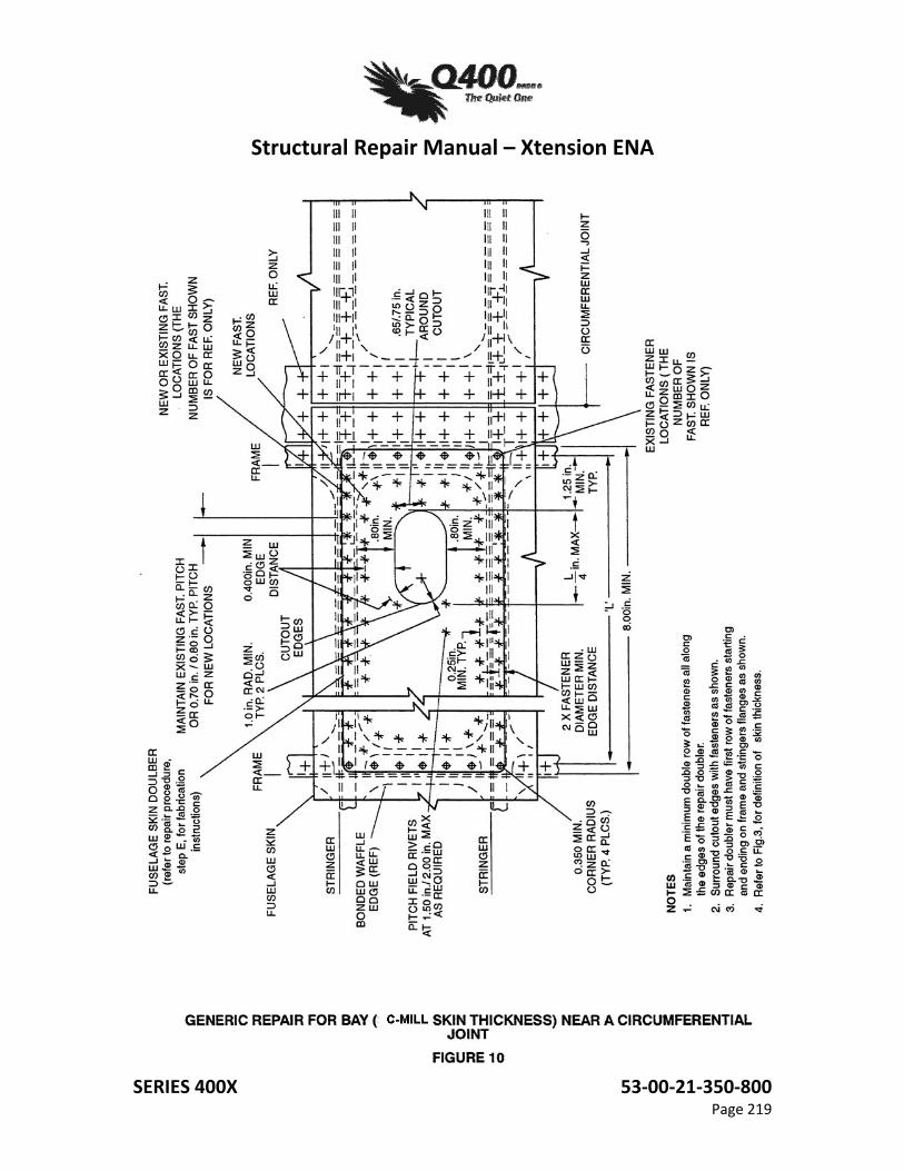
(4) Bay (C-Mill Skin Thickness) Near a Circumferential Joint: Figure 9, page 218 - Damage Cutout Procedure Figure 10. page 219 - Generic Repair Procedure
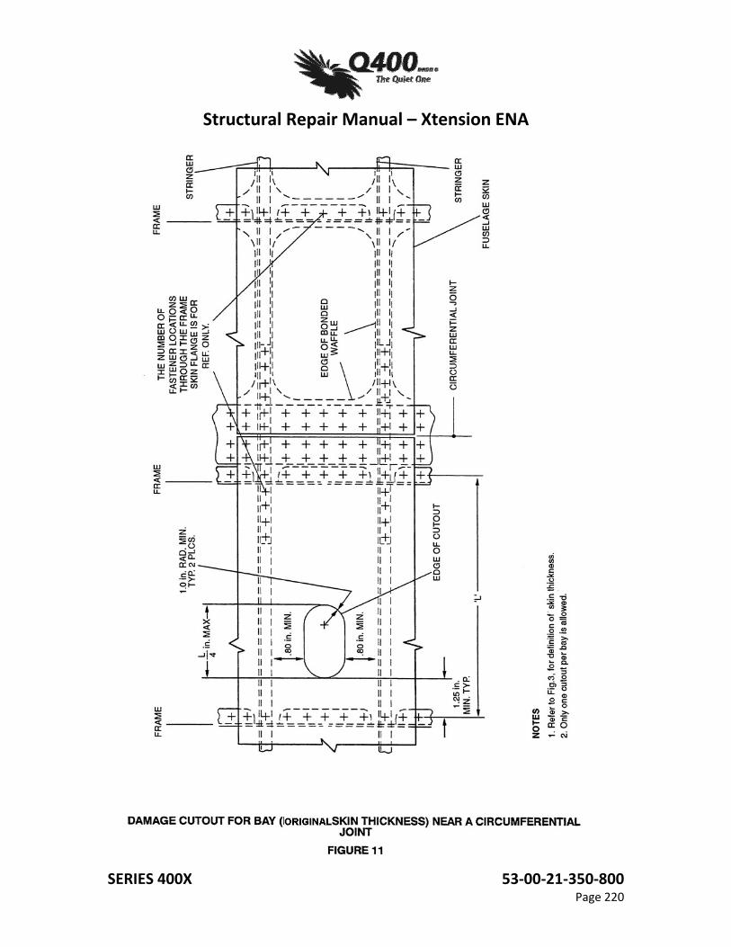
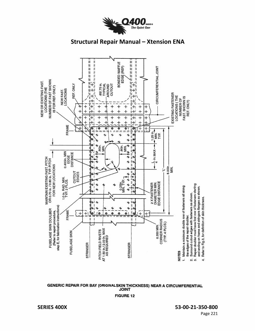
(5) Bay (Original Skin Thickness) Near a Circumferential Joint: Figure 11 , page 220 - Damage Cutout Procedure Figure 12, page 221 - Generic Repair Procedure
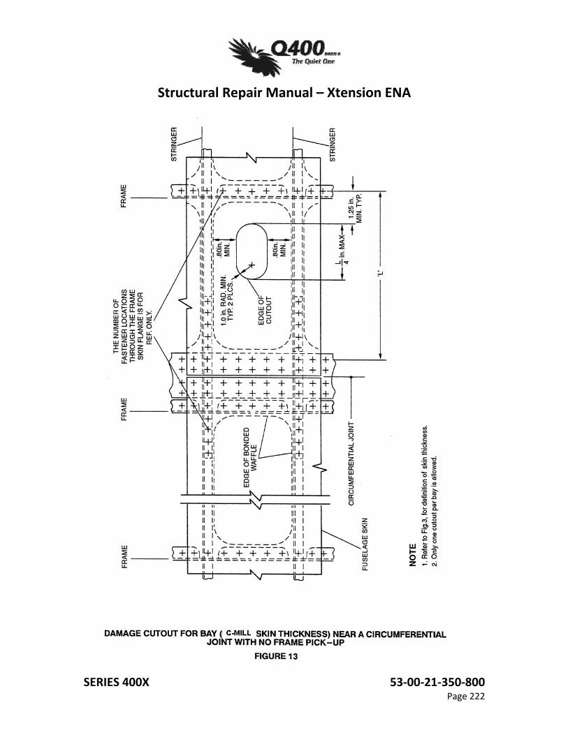
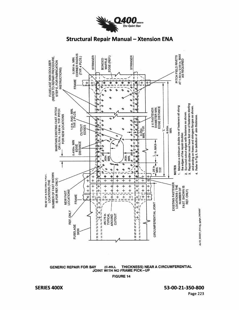
(6) Bay (C-Mill Skin Thickness) Near a Circumferential Joint with No Frame PickUp: Figure 13, page 222 - Damage Cutout Procedure Figure 14, page 223 - Generic Repair Procedure
Structural Repair Manual – Xtension ENA
SERIES 400X 53‐00‐21‐350‐800 Page 203
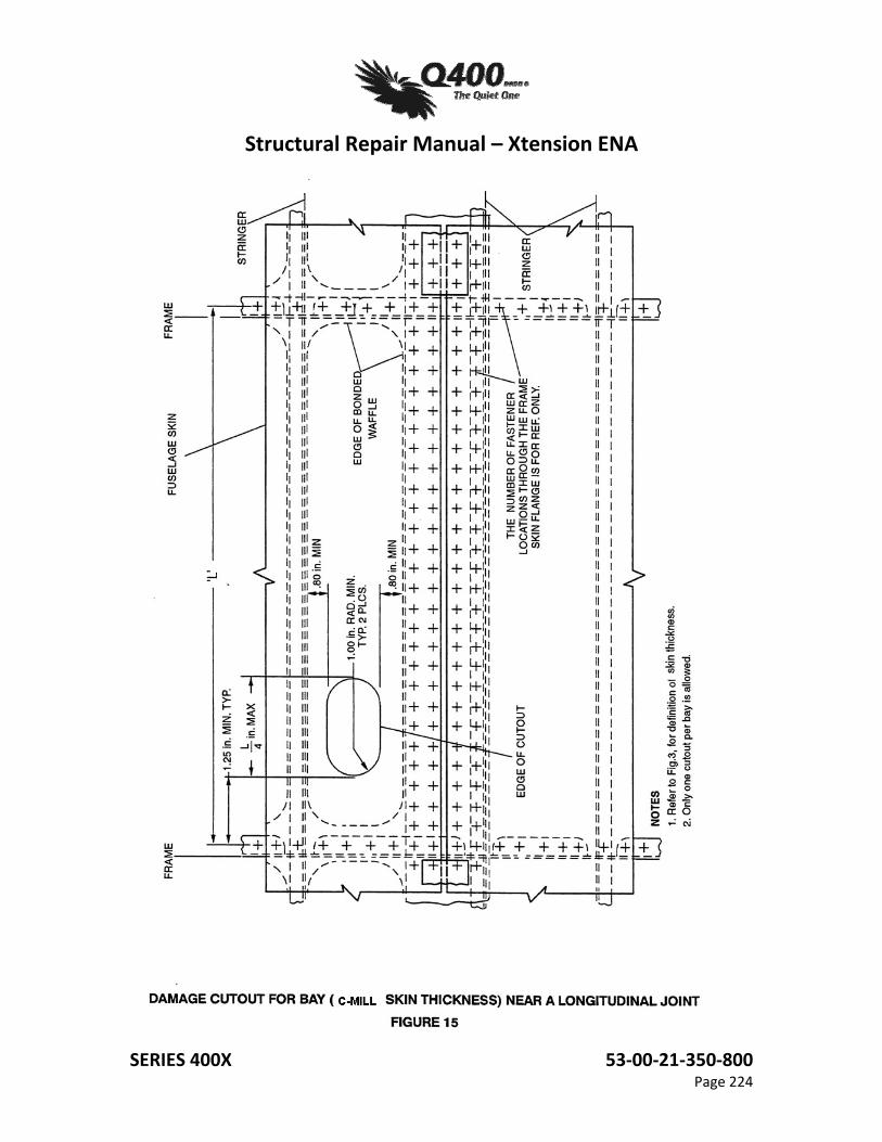
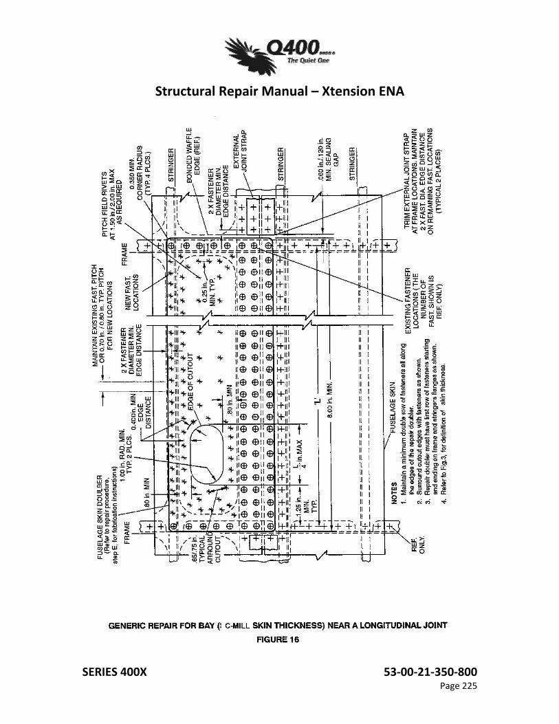
(7) Bay (C-Mill Skin Thickness) Near a Longitudinal Joint: Figure 15, page 224 - Damage Cutout Procedure Figure 16, page 225 - Generic Repair Procedure
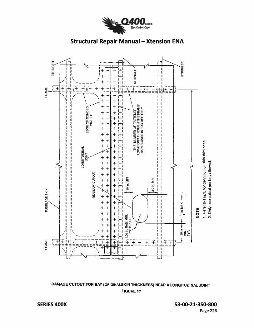
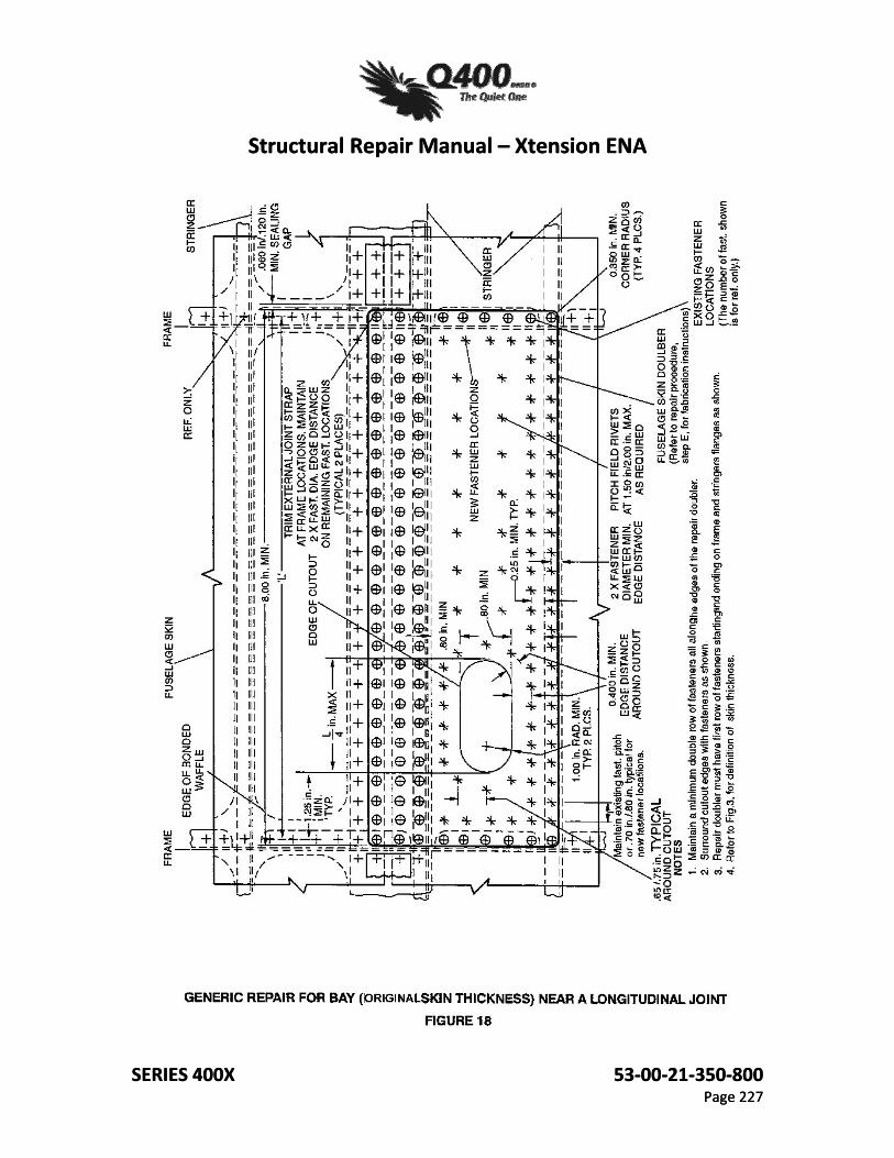
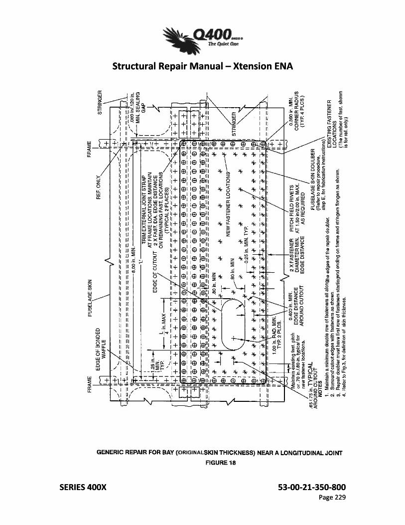
(8) Bay (Original Skin Thickness) Near a Longitudinal Joint: Figure 17, page 226 - Damage Cutout Procedure Figure 18, page 227 - Generic Repair Procedure
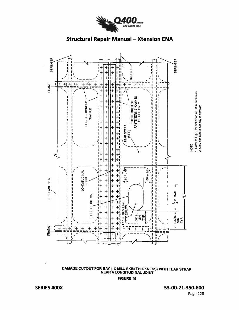
(9) Bay (C-Mill Skin Thickness) with Tear Strap Near a Longitudinal Joint: Figure 19, page 228 - Damage Cutout Procedure Figure 20, page 229 - Generic Repair Procedure
B. Before installing the repair, ultrasonic inspection of the stringers and bonded doublers is required to ensure that no disbonding is present in the repair area. If disbonding is found, contact Bombardier before proceeding further. Ultrasonic testing is the preferred method of inspection for skin/waffle/stringer disbonding. If this method is impractical, or if facilities are not available, Bombardier has no technical objection to the use of alternative non-destructive inspection procedures. The inspection procedure used must have approval from the appropriate airworthiness authority, and must be carried out by an operator with demonstrated expertise.
c. Ensure that in the repair area there is no damage to any other structural components such as frames, stringers, intercostals, etc.; also ensure that there is no damage or previous repairs in adjacent bays.
D. Damaged Area Removal.
NOTE: Do not hand dress or blend any damage prior to cutting out the damaged area. NOTE: Do not cut into the tear straps; this repair is nuIl and void if any damage exist or was created in the tear straps. (1) Damage is to be completely cut out by creating a circular or rectangular opening with
a 1.00" minimum corner radius as shown in Figure 3 and in the Damage Cutout Procedure Figures listed in paragraph A above. Use extreme caution not to damage adjacent structures.
(2) A Tear Strap is a region of double skin thickness found between two adjacent frame stations. It is formed by the internal waffle doubler on the fuselage skin and is approximately 3.00" wide. Refer to Fig 7 and Fig 19.
(3) After damage is completely cut out, crack inspect both the internai and external cut
surfaces using eddy current (preferred method) or fluorescent penetrant dye to ensure that no cracks exist.
(4) Smooth out ail cut edges. Ensure the cut edges are free of nicks and burrs and have
a minimum surface finish of RMS 125 or better. Touch up bare edges with alodine and epoxy primer.
Structural Repair Manual – Xtension ENA
SERIES 400X 53‐00‐21‐350‐800 Page 204
(5) Alodine according to the procedure Task 51-21-10-381-801.
(6) Epoxy Prime according to the procedure Task 51-25-10-370-801. E. Fabricate ·Repair Doubler
(1) Fabricate the external repair doubler from 2024-T3/T42 (QQ- A- 250/5) clad material.
(2) The required thickness of the repair doubler varies according to damage location; determine thickness as follows: one gage heavier than the damaged skin section to repair.
(3) Maintain a minimum corner radius of 0.350". (4) Form or roll the doubler to match the fuselage contour. (5) Finish the repair doubler with alodine and epoxy primer.
F. Prepare Area for Repair Doubler Installation
(1) Where necessary, carefully remove any existing rivets in the repair area.
(2) Drill new rivet holes as follows:
NOTE: Typical pitch for al additional fasteners is 0.70"/0.80" maximum.
(a) Using the holes of the rivets removed in step (1) as a guide, carefully mark out and drill new rivet holes in the skin and repair doubler. (b) Maintain a minimum edge distance of two times the fastener diameter,unless otherwise specified; the edge distance is measured from the center of the fastener hole to the edge of the material and must be maintained on all material through which the fastener passes. (c) When drilling new fastener holes maintain a minimum distance of 0.25" from the edges of waffle doublers (if applicable), and a minimum edge distance of 0.400" for all fasteners around the cutout. (3) According to the task 51-18-00-800-808, repair any fastener countersinks remaining in the skin underneath the external repair doubler.
Structural Repair Manual – Xtension ENA
SERIES 400X 53‐00‐21‐350‐800 Page 205
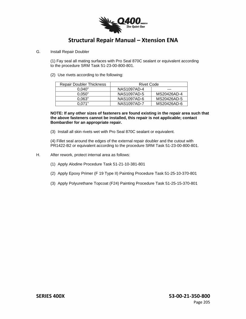
G. Install Repair Doubler
(1) Fay seal all mating surfaces with Pro Seal 870C sealant or equivalent according to the procedure SRM Task 51-23-00-800-801.
(2) Use rivets according to the following:
Repair Doubler Thickness Rivet Code
0,040” NAS1097AD-4 --- 0,050” NAS1097AD-5 MS20426AD-4 0,063” NAS1097AD-6 MS20426AD-5 0,071” NAS1097AD-7 MS20426AD-6
NOTE: If any other sizes of fasteners are found existing in the repair area such that the above fasteners cannot be installed, this repair is not applicable; contact Bombardier for an appropriate repair.
(3) Install all skin rivets wet with Pro Seal 870C sealant or equivalent.
(4) Fillet seal around the edges of the external repair doubler and the cutout with PR1422-B2 or equivalent according to the procedure SRM Task 51-23-00-800-801.
H. After rework, protect internal area as follows:
(1) Apply Alodine Procedure Task 51-21-10-381-801
(2) Apply Epoxy Primer (F 19 Type II) Painting Procedure Task 51-25-10-370-801 (3) Apply Polyurethane Topcoat (F24) Painting Procedure Task 51-25-15-370-801
Structural Repair Manual – Xtension ENA
SERIES 400X 53‐00‐21‐350‐800 Page 206
Structural Repair Manual – Xtension ENA
SERIES 400X 53‐00‐21‐350‐800 Page 207
Structural Repair Manual – Xtension ENA
SERIES 400X 53‐00‐21‐350‐800 Page 208
Structural Repair Manual – Xtension ENA
SERIES 400X 53‐00‐21‐350‐800 Page 208
Structural Repair Manual – Xtension ENA
SERIES 400X 53‐00‐21‐350‐800 Page 209
Structural Repair Manual – Xtension ENA
SERIES 400X 53‐00‐21‐350‐800 Page 210
Structural Repair Manual – Xtension ENA
SERIES 400X 53‐00‐21‐350‐800 Page 211
Structural Repair Manual – Xtension ENA
SERIES 400X 53‐00‐21‐350‐800 Page 211
Structural Repair Manual – Xtension ENA
SERIES 400X 53‐00‐21‐350‐800 Page 212
Structural Repair Manual – Xtension ENA
SERIES 400X 53‐00‐21‐350‐800 Page 213
Structural Repair Manual – Xtension ENA
SERIES 400X 53‐00‐21‐350‐800 Page 213
Structural Repair Manual – Xtension ENA
SERIES 400X 53‐00‐21‐350‐800 Page 214
A
Structural Repair Manual – Xtension ENA
SERIES 400X 53‐00‐21‐350‐800 Page 215
Structural Repair Manual – Xtension ENA
SERIES 400X 53‐00‐21‐350‐800 Page 215
Structural Repair Manual – Xtension ENA
SERIES 400X 53‐00‐21‐350‐800 Page 216
Structural Repair Manual – Xtension ENA
SERIES 400X 53‐00‐21‐350‐800 Page 216
Structural Repair Manual – Xtension ENA
SERIES 400X 53‐00‐21‐350‐800 Page 217
Structural Repair Manual – Xtension ENA
SERIES 400X 53‐00‐21‐350‐800 Page 217
Structural Repair Manual – Xtension ENA
SERIES 400X 53‐00‐21‐350‐800 Page 218
Structural Repair Manual – Xtension ENA
SERIES 400X 53‐00‐21‐350‐800 Page 219
Structural Repair Manual – Xtension ENA
SERIES 400X 53‐00‐21‐350‐800 Page 220
Structural Repair Manual – Xtension ENA
SERIES 400X 53‐00‐21‐350‐800 Page 221
Structural Repair Manual – Xtension ENA
SERIES 400X 53‐00‐21‐350‐800 Page 222
Structural Repair Manual – Xtension ENA
SERIES 400X 53‐00‐21‐350‐800 Page 223
Structural Repair Manual – Xtension ENA
SERIES 400X 53‐00‐21‐350‐800 Page 223
Structural Repair Manual – Xtension ENA
SERIES 400X 53‐00‐21‐350‐800 Page 224
Structural Repair Manual – Xtension ENA
SERIES 400X 53‐00‐21‐350‐800 Page 225
Structural Repair Manual – Xtension ENA
SERIES 400X 53‐00‐21‐350‐800 Page 226
Structural Repair Manual – Xtension ENA
SERIES 400X 53‐00‐21‐350‐800 Page 226
Structural Repair Manual – Xtension ENA
SERIES 400X 53‐00‐21‐350‐800 Page 227
Structural Repair Manual – Xtension ENA
SERIES 400X 53‐00‐21‐350‐800 Page 227
Structural Repair Manual – Xtension ENA
SERIES 400X 53‐00‐21‐350‐800 Page 228
Structural Repair Manual – Xtension ENA
SERIES 400X 53‐00‐21‐350‐800 Page 228
Structural Repair Manual – Xtension ENA
SERIES 400X 53‐00‐21‐350‐800 Page 229
Structural Repair Manual – Xtension ENA
SERIES 400X 53‐00‐21‐350‐800 Page 229