structural performance of cold-formed lean duplex ... · ec3 and direct strength ... steel hollow...
TRANSCRIPT
ADVANCES in NATURAL and APPLIED SCIENCES
ISSN: 1995-0772 Published BYAENSI Publication EISSN: 1998-1090 http://www.aensiweb.com/ANAS
2017 June 11(8): pages 202-211 Open Access Journal
ToCite ThisArticle: M. Anbarasu., Structural performance of cold-formed lean duplex stainless steel flat oval hollow columns. Advances in Natural and Applied Sciences. 11(8); Pages: 202-211
Structural performance of cold-formed lean duplex stainless steel flat oval hollow columns
M. Anbarasu Assistant Professor, Department of Civil Engineering, Government College of Engineering, Salem - 636 011, Tamilnadu, India. Received 28 February 2017; Accepted 22 May 2017; Available online 6 June 2017
Address For Correspondence: M. Anbarasu, Assistant Professor, Department of Civil Engineering, Government College of Engineering, Salem - 636 011, Tamilnadu, India. E-mail: gceanbu@gmail. com
Copyright © 2017 by authors and American-Eurasian Network for ScientificInformation (AENSI Publication). This work is licensed under the Creative Commons Attribution International License (CC BY). http://creativecommons.org/licenses/by/4.0/
ABSTRACT This paper deals with the numerical study on structural performance of the cold-formed lean duplex stainless steel (LDSS) flat oval hollow columns under axial compression. The flat oval hollow section consists of two flats and two semi-circular curved faces. Finite element (FE) models were developed up using the ABAQUS software and validated against the experimental results reported in the literature. Developed FE models included material, geometric nonlinearities as well as initial geometric imperfections. A comprehensive parametric study has been carried out by covering a wide range of slenderness with different cross section geometries for the considered flat oval hollow columns. Column resistances obtained from the numerical parametric study were compared with the current American specifications, AS/NZS standard, EC 3 code and Direct Strength Method (DSM) guidelines when applied for cold-formed lean duplex stainless steel columns. Reliability analysis was carried out to assess the reliability of the existing and proposed design rules for the lean duplex stainless steel flat oval hollow columns.
KEYWORDS: Direct Strength Method; Flat oval hollow columns, Lean duplex stainless steel; Local-flexural buckling;
Numerical modelling;
INTRODUCTION
The familiar range of tubular members currently comprises square, rectangular, and circular hollow
sections. The recently introduced structurally efficient section is flat oval hollow section. The low nickel
stainless steel alloy such as Lean Duplex Stainless Steel (LDSS) such as grade EN 1.4162 in particular, is
popular in recent years and it has increased strength compared to conventional austenitic and ferritic stainless
steels. Gardner et. al [1-2] studied the structural performance of hot-rolled structural steel elliptical hollow
sections. Ashraf et al. [3] reported the finite element modelling of different types of cross sections made up of
stainless steel. Gardner and Ashraf [4] developed two stage material model for stainless steel. Gardner and Chan
[5] developed cross section limits for the elliptical hollow sections. Silvestre [6] developed Generalised Beam
Theory (GBT) formulations for elastic buckling behaviour of elliptical cylindrical shells and tubes under
compression and validated the results by shell finite element analyses. Becque et al. [7] proposed modifications
to the direct strength method for stainless steel compression members. Based on the numerical and experimental
study, Theofanous and Gardner [8] proposed new design method for LDSS hollow section columns. Theofanous
et al. [9] performed experimental and numerical study on cold-formed stainless steel oval hollow sections
(OHS), and proposed a class 3 limit for stainless steel OHS in compression and a suitable buckling curve for
OHS columns. Chan and Gardner [10] conducted tests on hot-finished steel elliptical hollow sections, followed

203 M. Anbarasu., 2017/Advances in Natural and Applied Sciences. 11(8) June 2017, Pages: 202-211
by numerical parametric study, finally proposed design rules for the member buckling resistance of elliptical
hollow section columns. Huang and Young [11-13] performed experiments on LDSS hollow stub columns,
followed by wide range of numerical parametric study to propose design modifications to AS/NZ 4600-2005,
EC3 and Direct Strength Method for LDSS hollow columns. Zhu and Young [14-15] conducted tests on cold-
formed steel oval hollow section columns, then the experimental and numerical parametric column strengths are
compared with the design strengths calculated using the current North American, Australian/New Zealand,
European specifications and DSM for cold-formed steel structures, also evaluated the design rules by reliability
analysis. Patton and Singh [16] numerically examined the effect of different cross sections (Square, L-, T-,and
+-shaped cross sections) effect on ultimate strength of LDSS compression members. Sachidananda and Singh
[17] numerically investigates the effect of cross-section thickness, flat length and curvature of end parts, on the
compression resistance of the fixed ended LDSS (Lean Duplex Stainless Steel) flat oval stub columns also
compared the results with current design specifications. Anbarasu and Ashraf [18] developed DSM formulation
for cold-formed lean duplex stainless steel lipped channel columns, especially failed in local and global
buckling. Anbarasu and Ashraf [19] proposed modifications to AS/NZ specifications, European Specifications
and DSM specifications for cold-formed lean duplex stainless steel hollow columns subjected to local-flexural
buckling interaction.
This paper presents investigation on the behaviour and strength of flat oval hollow section columns based
on analytical and numerical studies. A finite element model is established with geometric and material non-
linearities and verified against the test results carried out by Zhu and Young [14]. Parametric study was
performed to investigate the effect of cross section geometries and member slenderness on the behavior flat oval
hollow columns. The results obtained from the finite element analysis were compared with design strengths
calculated using the American specifications (ASCE 8-02)[20], Australian/ New Zealand Standard (AS/NZS
4673)[21], European Specifications (EN 1993-1-4 [22]) and North American Specification direct strength
method (AISI S100-2007)[23] for cold-formed steel structures. The main focus of the work is to assess the
suitability of current codal provisions for the compression resistance of LDSS flat oval hollow columns.
1. Finite Element Modelling:
Numerical modelling was performed using the non-linear finite element (FE) analysis program, ABAQUS
version 6.10 [24] to predict the ultimate compression resistance and failure modes to simulate the behaviour of
cold-formed flat oval hollow columns test results published in [14]. The elements chosen for the FE models
were four-noded, reduced integration shell elements with six degrees of freedom per node in the ABAQUS
element library. This element has performed well in similar applications involving the modelling of LDSS
members [8]&[19]). Convergence studies were conducted to decide the appropriate mesh size of 5mm x 5mm
with the aim of minimum computational effort by performing elastic eigen value buckling analysis. The
Gardner-Ashraf material model [4] as shown in Eqn. 1 was used in the current study to investigate the behaviour
of LDSS flat oval hollow columns.
𝜀 =𝜎
𝐸0
+ 0.002 (𝜎
𝜎0.2
)𝑛
𝜎 ≤ 𝜎0.2
𝜀 =𝜎−𝜎0.2
𝐸0.2+ (𝜀𝑡1.0 − 𝜀𝑡0.2 −
𝜎1.0−𝜎0.2
𝐸0.2) (
𝜎−𝜎0.2
𝜎1.0−𝜎0.2)
𝑛′0.2,1.0+ 𝜀𝑡0.2 𝜎0.2 ≤ 𝜎 ≤ 𝜎𝑢 (1)
Where, σ and ε are engineering stress and strain, respectively. E0 is the initial tangent modulus, σ0.2 and
σ1.0 are the 0.2% and 1.0% proof stress respectively, σ1.0 is the ultimate tensile strength, n and n’0.2,1.0 are
strain hardening exponents for the compound Ramberg-Osgood model, εt1.0 and εt0.2 are the total strain
corresponding to σ1.0 and σ0.2 respectively.
Reference points (RP1 and RP2) were created at the geometric centroid of the section at both the ends of
the column. The column ends were constrained through multi point constraint (MPC) available in ABAQUS
[24]. The fixed-ended boundary condition was simulated by arresting all degrees of freedom at unloaded end. At
the loaded end, Except for the vertical translation, all degrees of freedom were restrained. This MPC acted as a
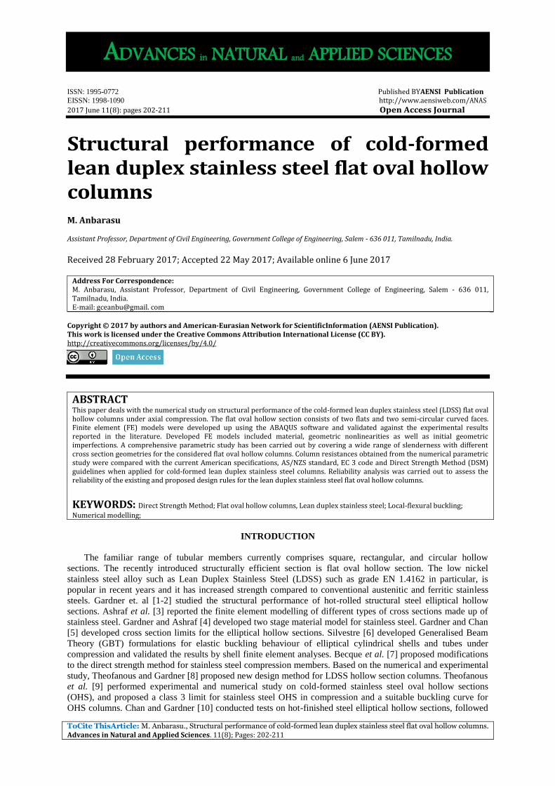
rigid surface that was rigidly connected to the upper and lower ends of the column (Fig. 1). The displacement
control loading method was used in FE models, which is identical to that used in the column tests. Fig.1
illustrates the application of load and boundary condition in the columns.
204 M. Anbarasu., 2017/Advances in Natural and Applied Sciences. 11(8) June 2017, Pages: 202-211
Fig. 1: Loading and Boundary condition
The local geometric imperfection of magnitude of 10% of plate thickness was used in the FE analysis as
proposed by Chan and Gardner [10]. The overall geometric imperfections value of L/1500 was also used in the
model where L is the specimen length, as suggested in [8]. Both local and global initial geometric imperfections
in the form of the lowest elastic and local and global buckling modes were incorporated into the models to
initiate the nonlinear analysis. Two types of analysis were performed for each model; linear elastic eigen
buckling analysis were initially carried out to determine buckling mode shapes, which were subsequently
incorporated in model to incorporate the geometric imperfections. The modified Riks method was employed for
the non-linear analyses, which enabled the post ultimate behaviour to be traced.
Validation:
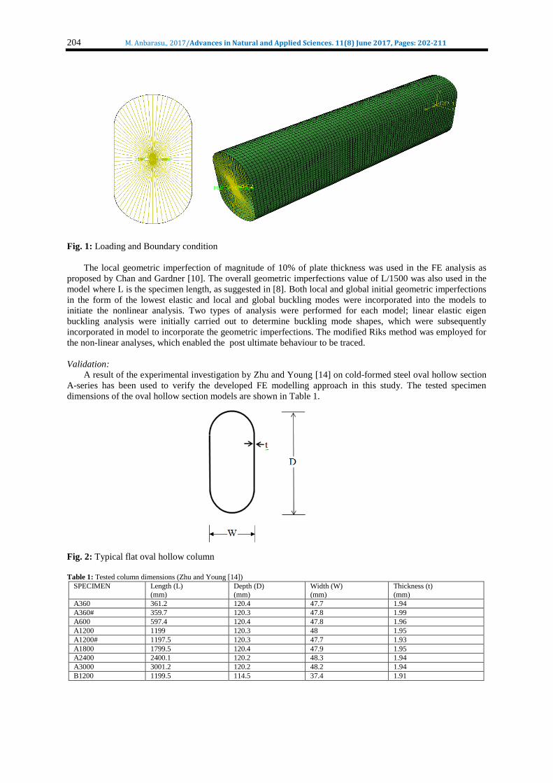
A result of the experimental investigation by Zhu and Young [14] on cold-formed steel oval hollow section
A-series has been used to verify the developed FE modelling approach in this study. The tested specimen
dimensions of the oval hollow section models are shown in Table 1.
Fig. 2: Typical flat oval hollow column
Table 1: Tested column dimensions (Zhu and Young [14])
SPECIMEN Length (L)
(mm)
Depth (D)
(mm)
Width (W)
(mm)
Thickness (t)
(mm)
A360 361.2 120.4 47.7 1.94
A360# 359.7 120.3 47.8 1.99
A600 597.4 120.4 47.8 1.96
A1200 1199 120.3 48 1.95
A1200# 1197.5 120.3 47.7 1.93
A1800 1799.5 120.4 47.9 1.95
A2400 2400.1 120.2 48.3 1.94
A3000 3001.2 120.2 48.2 1.94
B1200 1199.5 114.5 37.4 1.91

205 M. Anbarasu., 2017/Advances in Natural and Applied Sciences. 11(8) June 2017, Pages: 202-211
Table 2: Material Properties (Zhu and Young [14])
Coupon E (Gpa) σ0.2 (MPa) σu (MPa)
A (flat) 201.9 358.6 402.8
A(curved) 206.4 379.2 415.4
B (flat) 201.5 358.7 387.3
B(curved) 201.3 372.6 401.3
Table 2 shows the material properties of the sections considered for the validation. The comparison of FE
results with the test results for the oval hollow columns are shown and compared in Table 3. The mean ratio of
the ultimate resistance from the finite element model and experiment was 1.003 with a standard deviation of
0.010.
Table 3: Comparison of Experimental and FEA Ultimate Load
Specimen ID PEXP (kN) PFEA (kN) PEXP/ PFEA
A360 181.2 182.30 0.99
A360# 185.9 183.00 1.02
A600 196.0 194.87 1.01
A1200 190.3 187.27 1.02
A1200# 188.5 190.16 0.99
A1800 183.9 182.50 1.01
A2400 173.1 171.80 1.01
A3000 157.7 159.10 0.99
B1200 146.6 147.2 1.00
Mean 1.003
Std. Dev 0.010
Fig. 3 shows the comparison of the load vs end shortening curve for the test and FE analysis for the
specimen A360. Based on the comparison of results, a reasonable agreement has been achieved.
Fig. 3: Comparison of Test and FE Load vs end shortening curve for the specimen A360
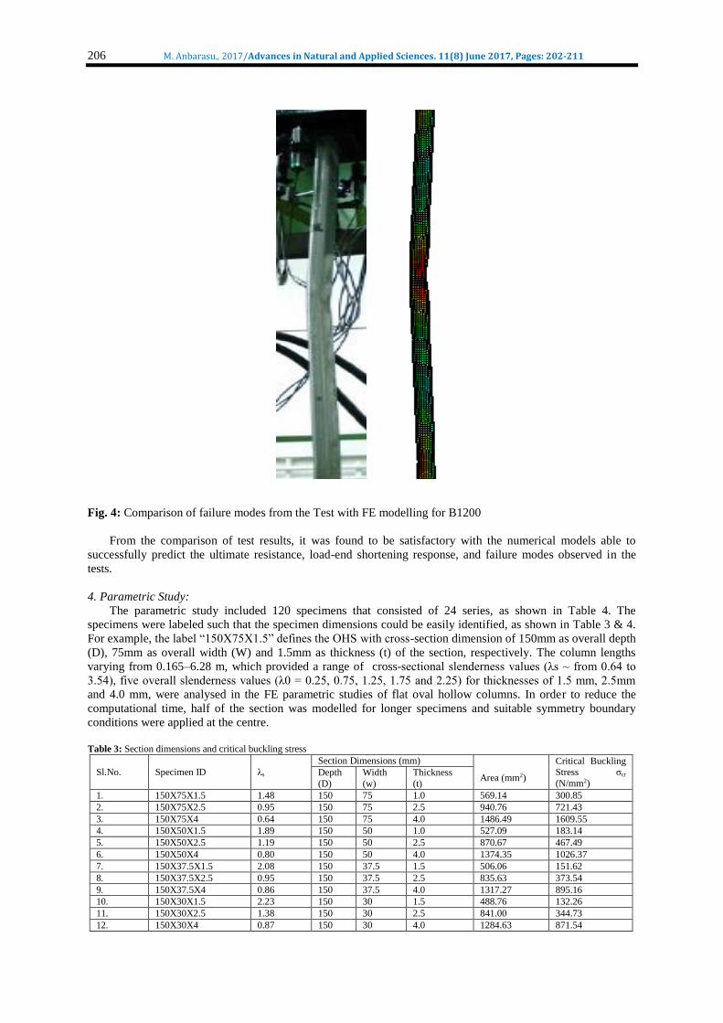
Comparison of failure mode predicted by FE modelling with the experimental one for the specimen B1200
is shown in Fig. 4.
0
20
40
60
80
100
120
140
160
180
200
0 1 2 3 4 5
Axis
Load
(k
N)
End Shortening (mm)
TEST
FEA
206 M. Anbarasu., 2017/Advances in Natural and Applied Sciences. 11(8) June 2017, Pages: 202-211
Fig. 4: Comparison of failure modes from the Test with FE modelling for B1200
From the comparison of test results, it was found to be satisfactory with the numerical models able to
successfully predict the ultimate resistance, load-end shortening response, and failure modes observed in the
tests.
4. Parametric Study:
The parametric study included 120 specimens that consisted of 24 series, as shown in Table 4. The
specimens were labeled such that the specimen dimensions could be easily identified, as shown in Table 3 & 4.
For example, the label “150X75X1.5” defines the OHS with cross-section dimension of 150mm as overall depth
(D), 75mm as overall width (W) and 1.5mm as thickness (t) of the section, respectively. The column lengths
varying from 0.165–6.28 m, which provided a range of cross-sectional slenderness values (λs ~ from 0.64 to
3.54), five overall slenderness values (λ0 = 0.25, 0.75, 1.25, 1.75 and 2.25) for thicknesses of 1.5 mm, 2.5mm
and 4.0 mm, were analysed in the FE parametric studies of flat oval hollow columns. In order to reduce the
computational time, half of the section was modelled for longer specimens and suitable symmetry boundary
conditions were applied at the centre.
Table 3: Section dimensions and critical buckling stress
Sl.No. Specimen ID λs
Section Dimensions (mm)
Area (mm2)
Critical Buckling Stress σcr
(N/mm2) Depth
(D)
Width
(w)
Thickness
(t)
1. 150X75X1.5 1.48 150 75 1.0 569.14 300.85
2. 150X75X2.5 0.95 150 75 2.5 940.76 721.43
3. 150X75X4 0.64 150 75 4.0 1486.49 1609.55
4. 150X50X1.5 1.89 150 50 1.0 527.09 183.14
5. 150X50X2.5 1.19 150 50 2.5 870.67 467.49
6. 150X50X4 0.80 150 50 4.0 1374.35 1026.37
7. 150X37.5X1.5 2.08 150 37.5 1.5 506.06 151.62
8. 150X37.5X2.5 0.95 150 37.5 2.5 835.63 373.54
9. 150X37.5X4 0.86 150 37.5 4.0 1317.27 895.16
10. 150X30X1.5 2.23 150 30 1.5 488.76 132.26
11. 150X30X2.5 1.38 150 30 2.5 841.00 344.73
12. 150X30X4 0.87 150 30 4.0 1284.63 871.54

207 M. Anbarasu., 2017/Advances in Natural and Applied Sciences. 11(8) June 2017, Pages: 202-211
13. 250x125x1.5 2.36 250 125 1.5 953.25 118.26
14. 250x125x2.5 1.51 250 125 2.5 1580.94 289.08
15. 250x125x4 1.01 250 125 4.0 2510.78 650.43
16. 250x83.33x1.5 3.02 250 83.33 1.5 883.15 72.27
17. 250x83.33x2.5 1.92 250 83.33 2.5 1461.12 177.39
18. 250x83.33x4 1.25 250 83.33 4.0 2323.86 420.48
19. 250x62.5x1.5 3.33 250 62.50 1.5 848.11 59.13
20. 250x62.5x2.5 2.13 250 62.50 2.5 1405.72 144.54
21. 250x62.5x4 1.40 250 62.50 4.0 2230.42 335.07
22. 250x50x1.5 3.54 250 50 1.5 827.09 52.56
23. 250x50x2.5 2.29 250 50 2.5 1370.67 124.83
24. 250x50x4 1.46 250 50 4.0 2174.35 308.79
The overall slenderness λ0 of a stainless steel column is commonly defined as:
0 = √σ0.2%/σE = (Le
r)√σ0.2%/π2E0 (2)
Where, σ0.2% = 0.2% proof stress, Le = Effective length of the column, r = radius of gyration, E0 = initial
modulus. The cross-sectional slenderness λs is defined as:
s = √σ0.2%/σcr (3)
In the parametric study, theoretical and numerical analysis was carried out for the selected cross-sections
for the 0.2% proof stress value of the flat and curved portion, shown in Table 5 [8] is used in deriving stress
strain of LDSS material.
Table 5: Material properties for parametric study (Theofanous and Gardner [8])
Specimen ID E
(N/mm2)
σ0.2
(N/mm2)
σ1.0
(N/mm2)
σu
(N/mm2)
Compound R-O
Coefficients
n n'
100x100x4 Flat 198800 586 632 761 9.0 2.8
Corner 206000 811 912 917 6.3 4.1
The unfactored design strengths (nominal strengths) were calculated using the ASCE 8-02 [20],
Australian/New Zealand Standard (AS/NZS) [21] for cold-formed stainless steel structures, European Code
(EC3) [22]: Design of steel structures—Part 1.4: General rules—Supplementary rules for stainless steels and
Direct Strength Method (AISI-S100:2007) [23] for cold-formed steel structures. Table 6 compares the FE
analysis results with the results obtained from current ASCE 8-02, AS/NZS, EC3 and DSM codal provisions,
for LDSS flat oval hollow columns.
Table 6: Comparison of Results
Specimen ID λ0 PFEA
(kN)
PFEA /
PASCE
PFEA /
PAS/NZ PFEA/ PEN PFEA / PDSM
150X75X1.5
0.25 263.36 0.85 0.85 0.90 1.09
0.75 260.47 0.84 1.02 0.89 1.11
1.25 222.23 0.80 0.98 0.84 1.02
1.75 192.92 0.83 0.98 0.88 0.98
2.25 157.72 0.82 0.96 0.92 0.92
150x75x2.5
0.25 509.20 0.88 0.88 0.94 0.94
0.75 499.60 0.87 1.05 0.92 0.96
1.25 470.50 0.90 1.11 0.98 0.97
1.75 498.20 1.15 1.36 1.28 1.14
2.25 325.17 0.91 1.08 1.09 0.89
150x75x4
0.25 1045.65 1.07 1.07 1.08 1.08
0.75 1043.29 1.07 1.33 1.08 1.13
1.25 849.91 0.98 1.24 1.02 1.02
1.75 730.78 1.04 1.25 1.12 1.03
2.25 539.24 0.94 1.14 1.10 0.94
150x50x1.5
0.25 210.02 0.89 0.89 0.96 1.11
0.75 196.45 0.83 1.00 0.90 1.08
1.25 193.96 0.91 1.10 0.94 1.14
1.75 150.51 0.84 0.98 0.85 0.98
2.25 127.76 0.84 0.98 0.88 0.95
150x50x2.5
0.25 413.14 0.89 0.89 0.97 0.96
0.75 398.91 0.86 1.02 0.94 0.96
1.25 350.69 0.83 1.01 0.90 0.90
1.75 319.68 0.90 1.04 0.98 0.91
2.25 308.68 1.03 1.20 1.20 1.01
150x50x4 0.25 869.13 1.00 1.00 1.09 0.99
0.75 828.17 0.95 1.14 1.04 0.98
208 M. Anbarasu., 2017/Advances in Natural and Applied Sciences. 11(8) June 2017, Pages: 202-211
1.25 737.14 0.94 1.16 1.05 0.96
1.75 613.34 0.94 1.13 1.08 0.94
2.25 491.65 0.93 1.12 1.13 0.93
150x37.5x1.5
0.25 174.18 0.88 0.88 0.96 1.03
0.75 164.49 0.83 0.98 0.91 1.00
1.25 164.27 0.91 1.09 0.94 1.07
1.75 165.17 1.08 1.25 1.08 1.19
2.25 164.84 1.27 1.47 1.29 1.36
150x37.5x2.5
0.25 383.44 0.94 0.94 1.06 1.00
0.75 572.13 1.41 1.67 1.57 1.54
1.25 422.51 1.14 1.37 1.24 1.22
1.75 358.73 1.14 1.31 1.24 1.15
2.25 232.12 0.87 1.00 0.99 0.85
150x37.5x4
0.25 809.46 1.03 1.03 1.14 1.00
0.75 772.94 0.98 1.16 1.09 0.99
1.25 680.19 0.95 1.14 1.07 0.94
1.75 574.38 0.95 1.11 1.10 0.91
2.25 461.87 0.91 1.10 1.14 0.91
150x30x1.5
0.25 162.30 1.04 1.04 1.05 1.05
0.75 146.89 0.94 1.03 0.95 0.98
1.25 146.46 0.98 1.09 0.97 1.04
1.75 145.24 1.07 1.16 1.08 1.14
2.25 100.21 0.81 0.89 0.87 0.90
150x30x2.5
0.25 336.82 0.87 0.87 1.03 0.93
0.75 323.57 0.83 0.99 0.99 0.92
1.25 347.45 0.98 1.17 1.12 1.06
1.75 347.41 1.16 1.33 1.30 1.17
2.25 348.12 1.36 1.57 1.59 1.35
150x30x4
0.25 842.02 1.14 1.14 1.29 1.08
0.75 750.12 1.02 1.20 1.15 0.99
1.25 643.88 0.95 1.14 1.09 0.92
1.75 597.40 1.04 1.20 1.21 0.97
2.25 443.64 0.91 1.08 1.15 0.89
250x125x1.5
0.25 383.83 0.82 0.82 0.85 0.93
0.75 372.54 0.79 0.97 0.83 0.94
1.25 329.56 0.78 0.97 0.79 0.89
1.75 329.10 0.94 1.12 0.94 0.98
2.25 327.29 1.14 1.34 1.18 1.12
250x125x2.5
0.25 661.68 0.77 0.77 0.81 0.97
0.75 678.29 0.79 0.96 0.83 1.03
1.25 620.83 0.80 0.99 0.84 1.01
1.75 695.78 1.08 1.27 1.14 1.25
2.25 677.07 1.26 1.49 1.41 1.40
250x125x4
0.25 1430.43 0.94 0.94 1.00 1.04
0.75 1316.51 0.86 1.05 0.92 0.99
1.25 1208.52 0.88 1.08 0.95 0.97
1.75 1112.14 0.97 1.15 1.08 0.99
2.25 874.90 0.92 1.09 1.10
0.92
250x83.33x1.5
0.25 266.21 0.78 0.78 0.82 1.15
0.75 274.99 0.80 0.97 0.85 1.23
1.25 252.81 0.82 1.00 0.81 1.21
1.75 251.81 0.98 1.15 0.93 1.33
2.25 174.52 0.81 0.95 0.77 1.05
250x83.33x2.5
0.25 579.17 0.89 0.89 0.96 1.07
0.75 554.51 0.85 1.02 0.92 1.06
1.25 527.81 0.89 1.08 0.93 1.08
1.75 544.92 1.09 1.28 1.11 1.24
2.25 532.38 1.27 1.48 1.33 1.38
250x83.33x4
0.25 1135.40 0.93 0.93 1.02 1.01
0.75 1042.41 0.85 1.02 0.93 0.96
1.25 1044.48 0.94 1.14 1.02 1.03
1.75 1047.60 1.12 1.30 1.22 1.15
2.25 656.60 0.83 0.97 0.96 0.83
250x62.5x1.5
0.25 225.34 0.81 0.81 0.87 1.13
0.75 220.19 0.79 0.95 0.85 1.14
1.25 203.83 0.81 0.98 0.80 1.13
1.75 169.24 0.80 0.93 0.74 1.03
2.25 147.00 0.82 0.96 0.75 1.02
250x62.5x2.5 0.25 483.97 0.88 0.88 0.97 1.05
0.75 446.53 0.81 0.96 0.89 1.00

209 M. Anbarasu., 2017/Advances in Natural and Applied Sciences. 11(8) June 2017, Pages: 202-211
1.25 431.24 0.86 1.03 0.89 1.03
1.75 450.15 1.06 1.23 1.06 1.19
2.25 453.21 1.26 1.45 1.27 1.37
250x62.5x4
0.25 905.29 0.85 0.85 0.95 0.92
0.75 844.97 0.79 0.94 0.89 0.89
1.25 823.20 0.85 1.01 0.92 0.92
1.75 722.11 0.87 1.01 0.95 0.90
2.25 637.26 0.91 1.05 1.03 0.91
250x50x1.5
0.25 205.81 0.85 0.85 0.93 1.10
0.75 186.73 0.77 0.92 0.84 1.04
1.25 188.31 0.86 1.04 0.85 1.11
1.75 178.27 0.96 1.12 0.89 1.16
2.25 190.17 1.21 1.41 1.09 1.42
250x50x2.5
0.25 459.77 0.94 0.94 1.05 1.08
0.75 408.91 0.84 0.99 0.93 0.99
1.25 380.75 0.85 1.02 0.89 0.99
1.75 333.66 0.87 1.01 0.88 0.96
2.25 276.75 0.85 0.98 0.85 0.91
250x50x4
0.25 1019.14 1.05 1.05 1.19 1.09
0.75 863.40 0.89 1.05 1.01 0.96
1.25 784.63 0.88 1.05 0.97 0.93
1.75 672.84 0.88 1.02 0.96 0.88
2.25 591.06 0.91 1.04 1.02 0.89
Mean 0.936 1.074 1.009 1.041
Std. Dev. 0.132 0.167 0.156 0.133
Capacity reduction factor (φ) 0.85 0.90 0.91 0.85
Reliability index (0) 2.25 2.35 2.17 2.69
The specimens of short in length mainly failed in local buckling. The long column specimens are failed in
minor axis flexural buckling and the intermediate length specimens failed in combined local and flexurl
buckling as expected and the deformed shape from finite element analysis for the 150x75x1.5 and 150x75x2.5
series are shown in Fig. 5. The reliability of the current design rules for cold-formed-steel columns was
evaluated by using reliability analysis. Reliability analysis is detailed in the commentary on the North American
specification [23] for the design of cold-formed-steel structural members and described in [15]. The load
combinations with resistance factors (ϕ) of for concentrically loaded compression members were used in
calculating the reliability index β0 for ASCE, AS/NZS, EC3 and DSM are as described by authors in [27-28].
(a) For 150x75x1.5 (b)For 150x75x2.5
Fig. 5: Deformation shapes
210 M. Anbarasu., 2017/Advances in Natural and Applied Sciences. 11(8) June 2017, Pages: 202-211
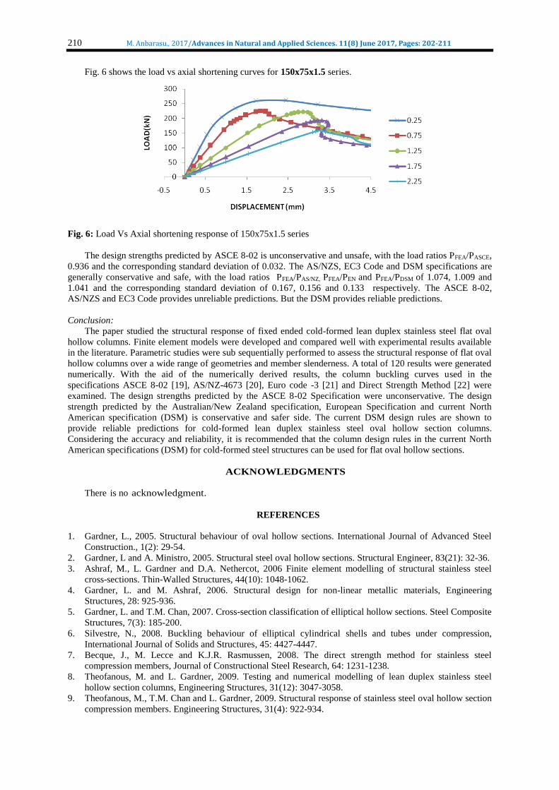
Fig. 6 shows the load vs axial shortening curves for 150x75x1.5 series.
Fig. 6: Load Vs Axial shortening response of 150x75x1.5 series
The design strengths predicted by ASCE 8-02 is unconservative and unsafe, with the load ratios PFEA/PASCE,
0.936 and the corresponding standard deviation of 0.032. The AS/NZS, EC3 Code and DSM specifications are
generally conservative and safe, with the load ratios PFEA/PAS/NZ, PFEA/PEN and PFEA/PDSM of 1.074, 1.009 and
1.041 and the corresponding standard deviation of 0.167, 0.156 and 0.133 respectively. The ASCE 8-02,
AS/NZS and EC3 Code provides unreliable predictions. But the DSM provides reliable predictions.
Conclusion:
The paper studied the structural response of fixed ended cold-formed lean duplex stainless steel flat oval
hollow columns. Finite element models were developed and compared well with experimental results available
in the literature. Parametric studies were sub sequentially performed to assess the structural response of flat oval
hollow columns over a wide range of geometries and member slenderness. A total of 120 results were generated
numerically. With the aid of the numerically derived results, the column buckling curves used in the
specifications ASCE 8-02 [19], AS/NZ-4673 [20], Euro code -3 [21] and Direct Strength Method [22] were
examined. The design strengths predicted by the ASCE 8-02 Specification were unconservative. The design
strength predicted by the Australian/New Zealand specification, European Specification and current North
American specification (DSM) is conservative and safer side. The current DSM design rules are shown to
provide reliable predictions for cold-formed lean duplex stainless steel oval hollow section columns.
Considering the accuracy and reliability, it is recommended that the column design rules in the current North
American specifications (DSM) for cold-formed steel structures can be used for flat oval hollow sections.
ACKNOWLEDGMENTS
There is no acknowledgment.
REFERENCES
1. Gardner, L., 2005. Structural behaviour of oval hollow sections. International Journal of Advanced Steel
Construction., 1(2): 29-54.
2. Gardner, L and A. Ministro, 2005. Structural steel oval hollow sections. Structural Engineer, 83(21): 32-36.
3. Ashraf, M., L. Gardner and D.A. Nethercot, 2006 Finite element modelling of structural stainless steel
cross-sections. Thin-Walled Structures, 44(10): 1048-1062.
4. Gardner, L. and M. Ashraf, 2006. Structural design for non-linear metallic materials, Engineering
Structures, 28: 925-936.
5. Gardner, L. and T.M. Chan, 2007. Cross-section classification of elliptical hollow sections. Steel Composite
Structures, 7(3): 185-200.
6. Silvestre, N., 2008. Buckling behaviour of elliptical cylindrical shells and tubes under compression,
International Journal of Solids and Structures, 45: 4427-4447.
7. Becque, J., M. Lecce and K.J.R. Rasmussen, 2008. The direct strength method for stainless steel
compression members, Journal of Constructional Steel Research, 64: 1231-1238.
8. Theofanous, M. and L. Gardner, 2009. Testing and numerical modelling of lean duplex stainless steel
hollow section columns, Engineering Structures, 31(12): 3047-3058.
9. Theofanous, M., T.M. Chan and L. Gardner, 2009. Structural response of stainless steel oval hollow section
compression members. Engineering Structures, 31(4): 922-934.

211 M. Anbarasu., 2017/Advances in Natural and Applied Sciences. 11(8) June 2017, Pages: 202-211
10. Chan, T.M. and L. Gardner, 2009. Flexural buckling of elliptical hollow section columns. Journal of
Structural Engineering, 135(5): 546-557.
11. Huang, Y., and B. Young, 2012. Material properties of cold-formed lean duplex stainless steel sections,
Thin-Walled Structures, 54: 72-81.
12. Huang, Y., B. Young, 2014. Structural performance of cold-formed lean duplex stainless steel columns,
Thin-Walled Structures, 83: 59-69.
13. Huang, Y., and B. Young, 2014. Tests of pin-ended cold-formed lean duplex stainless steel columns,
Journal of constructional steel research, 83: 59-69.
14. Zhu, J.H., B. Young, 2011. Cold-formed-steel oval hollow sections under axial compression. Journal of
Structural Engineering ASCE 137(7): 719-27.
15. Zhu, J.H., B. Young, 2012. Design of cold-formed steel oval hollow section columns. Journal of
constructional steel research, 71: 26-37.
16. Patton, M.L., and K.D. Singh, 2012. Numerical modelling of lean duplex stainless steel hollow columns of
square, L-,T-,and +-shaped cross sections under pure axial compression, Thin-Walled Structures, 53: 1-8.
17. Sachidananda, K., K.D. Singh, 2015. Numerical study of fixed ended lean duplex stainless steel (LDSS) flat
oval hollow stub column under pure axial compression, Thin-Walled Structures, 96: 105-119.
18. Anbarasu, M., and M. Ashraf, 2016. Behaviour and design of cold-formed lean duplex stainless steel lipped
channel columns, Thin-Walled Structures, 104: 106-115.
19. Anbarasu, M., and M. Ashraf, 2017. Interaction of local-flexural buckling for cold-formed lean duplex
stainless steel hollow columns, Thin-Walled Structures, 112: 20-30.
20. ASCE. 2002. Specification for the design of cold-formed stainless steel structural members. SEI/ASCE8-
02; Reston, VA: American Society of Civil Engineers.
21. AS/NZS. 2001. Cold-formed stainless steel structures. Australian/New Zealand Standard, AS/NZS
4673:2001. Sydney, Australia: Standards Australia.
22. EC3. 2006. Design of steel structures – Part 1.4: General rules – Supplementary rules for stainless steels.
European Committee for Standardization, EN1993-1-4, Brussels.
23. American Iron and Steel Institute (AISI), 2007. North American Specification (NAS) for the Design of
Cold-Formed Steel Structural Members, Washington DC.
24. ABAQUS, 2011. Standard User's Manual. Dassault Systemes Simulia Corporation, Version 6.11, USA.
25. Schafer, B.W., 2006. CUFSM3.12, elastic buckling analysis of thin-walled members by finite strip analysis.
⟨www.ce.jhu.edu/bschafer/cufsm⟩. 26. EN 10088-4. 2009. Stainless steels part 4: Technical delivery conditions for sheet/ plate and strip of
corrosion resisting steels for general purposes. CEN.
27. Anbarasu, M. and G. Murugapandian, 2016. Experimental study on distortional-global buckling mode
interaction on thin-walled lipped channel. Materials and Structures, 49(4): 1433-1442.
28. Anbarasu, M., 2016. Local-distortional buckling interaction on cold-formed steel lipped channel beams,
Thin-Walled Structures, 98: 351-359.