structural modelling of inversion structures: a case …spgindia.org/10_biennial_form/p065.pdftwo...
TRANSCRIPT

BRG, Room No-200V, KDMIPE, Dehradun,
10th Biennial International Conference & Exposition
P 065
Structural Modelling of Inversion Structures: A case study on
South Cambay Basin
Dr. Mayadhar Sahoo & S.K Chakrabarti
Summary
The inversion in South Cambay Basin is attributed to multi-phase tectonic evolutions, which include extension with syn-rift
deposits from Late Cretaceous to Lower Early Eocene, thermal sag with subsidence from Lower Early Eocene to Miocene and
a Post- Miocene to Recent period of folding, fault reactivation, structural inversion and erosion. The inversion structures as
interpreted in the Basin are classified as positive inversion styles
.
Two different inversion styles have been modelled by applying trishear-move on-fault algorithm using 2D Move software.
Fault reactivated inversions were observed in Narmada Section where the syn-rift beds show minimum reverse separation.
The the magnitude of extension as well as orientation of syn-rift faults in response to regional compression during inversion
have controlled the geometry of fault reactivated inversion structures. The Broach Section shows cover folded inversion styles,
where the normal faults have not reactivated during inversion. Thus the style of inversion might be controlled by deeper faults
in the basement which form an anti-formal regional geometry on fault bounded graben.
The quantification of inversion has been carried out using 2D Move software. The degree of fault inversion has been calculated
as ratio between reverse slip components during contraction to normal slip components during extension along particular
fault. It has been noticed in Narmada Section that all three fault reactivated inversions have <1 inversion ratio and are
classified as moderate inversion structures. The horizontal inversion ratio has also been estimated to constrain the relative
amount of shortening with respect to extension of structures of the basin. Hence it has been concluded that both fault
reactivated inversion and horizontal inversion ratios are influenced by amount of extension.
The study will help to find out: with same amount of shortening, the structures with small amount of extension will have greater
inversion ratio than one with large amount of extension.
Introduction
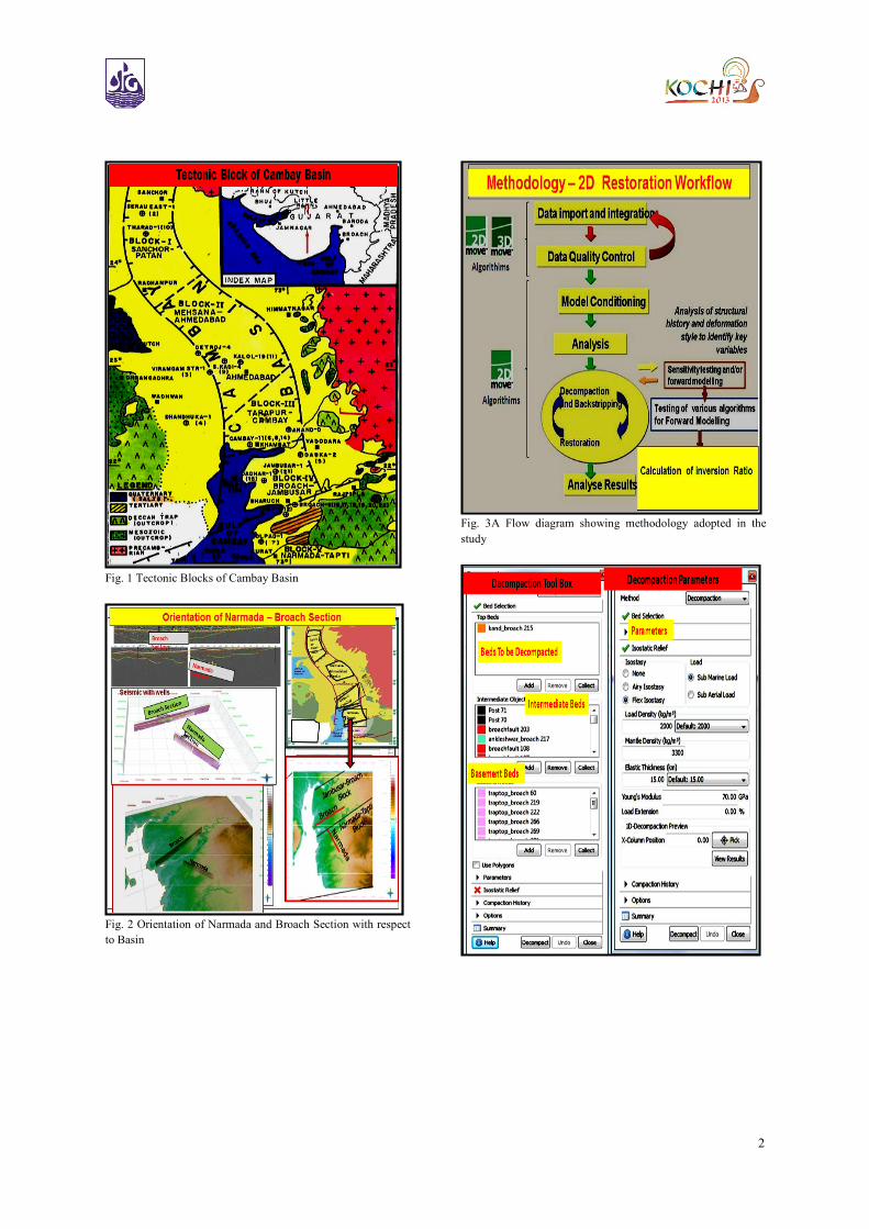
Cambay basin is an aborted rift basin formed during the
late Cretaceous time, which is situated in the western part
of the Indian shield. The basin is a narrow, elongated, rift
basin located between Saurashtra peninsula in the west,
Aravalli Hills in the northeast and Deccan craton to the
southeast (Fig. 1). The present study area is limited
between Mahisagar river in the north and Tapti river in the
south covering the Jambusar – Broach Block and the
Narmada-Tapti Block of Cambay Basin (Fig. 2). The
inversion structures observed in this part of the basin have
been attributed to multi-phase tectonic evolution, that
include extension with syn-rift deposits from Late
Cretaceous to Lower Early Eocene , thermal sag with
subsidence from Lower Early Eocene to Miocene and a
Post-Miocene to Recent period of folding, fault
reactivation, structural inversion and erosion.
Objective of the Study
Based on the interpretation of 2D seismic data, the
geometry of inversion has been modelled by applying
trishear-move on-fault algorithm using 2D Move software.
The quantification of inversion has also been carried out
using 2D Move software to know the degree of inversion
along the fault. The degree of fault inversion is the ratio
between reverse slip component during contraction to
normal slip component during extension along a particular
fault (Buchanan, 1995).
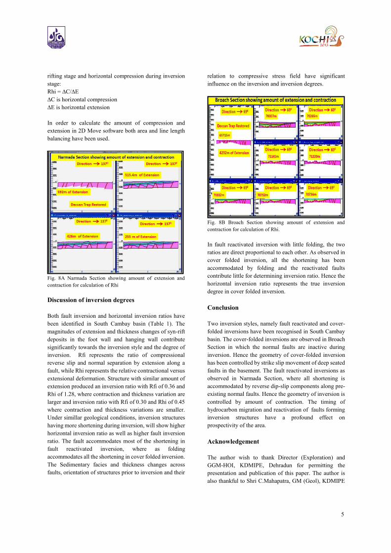
Methodology
The methodology for estimation of degree of inversion and
geometry of inversion styles are given in the flow diagram
(Fig. 3A & 3B):
2
Fig. 1 Tectonic Blocks of Cambay Basin
Fig. 2 Orientation of Narmada and Broach Section with respect
to Basin
Fig. 3A Flow diagram showing methodology adopted in the
study

3
Fig. 3B 2D Move data base used in the study
Inversion Styles
The structural styles of inverted basins are dissimilar to
each other according to their pre-inversion configuration,
lithologic composition of syn-rift sediments, degree of
inversion and the orientation of basin axis relative to
greatest principal stress which induced inversion
(Buchanan, 1995). In the present study area, two different
inversion styles have been modelled by applying trishear-
move on-fault algorithm using 2D Move software. They
are classified as fault reactivated and cover folded
inversion styles (Fig. 5A & 5B). The fault reactivated
inversions as observed in Narmada Section, in which, the
syn-rift beds show minimum reverse separations (Fig. 4).
Therefore, the magnitude of extension as well as
orientation of syn-rift faults in response to regional
compression has controlled the geometry of fault
reactivated inversion styles. The Broach Section shows
cover folded inversion styles, in which the normal faults
have not been reactivated during inversion. Therefore, it
has been interpreted that the geometry style of inversion
might have been controlled by deeper strike-slip faults in
the basement, form an anti-formal regional geometry on
fault bounded graben.
Fig. 4 Narmada Section showing fault reactivated inversion
structures
Fault – reactivated inversion ratio
Fault reactivated inversion structure is described as the
structure in which reverse slip component formed by
compression is accommodated along a pre-existing normal
fault. The normal faults developed during rifting might
have been dormant or showed little movement during post-
rift subsidence. These normal faults have been reactivated
as reverse faults when the basin undergoes compression or
strike-slip stress regime. Such inverted structures have
been observed in south Cambay basin. These inversion
structures are formed, where the syn-rift faults are oriented
<45° to the orientation of maximum horizontal stress. In
present day the south Cambay basin is undergoing in
transition phase from extensional stress regime to strike-
slip stress regime, where Shmin<Sv<Shmax (Sahoo et al.,
2011).
Fig. 5A Forward modelling of inversion structures in Narmada
Section
Fig. 5B Forward modelling of inversion structures in Narmada
Section

4
Forward Modelling of Inversion Styles
Forward modelling has been carried out using trishear-
move-on fault algorithm in Narmada Section. Different
amount of reverse displacements of hanging wall have
been measured along the three faults in Narmada Section.
Three Fault-related folding inversion structures have been
modelled, which are categorized as positive inversion
structures. These inversions depict differential shortening,
which are accommodated both by reverse slip along the
faults and by folding of sequences. The Fault 1 in Narmada
Section (Fig. 5A) shows small amount of reverse slip of
100m and has not propagated to shallow levels. Hence
folding of horizons accommodate most of the shortening.
Fault 2 shows reverse slip of 200m. The folding of the post
rift sediments accompanies the reactivation of pre existing
fault that controls the half-grabens formed during late
cretaceous rifting. The post rift sequences in the hanging
wall from Cambay shale to top surface have been uplifted
and formed anticlinal structures in response to reactivation
of syn-rift normal faults.
The fault in SE part of the Narmada Section shows the
hanging wall displacements of 250m which has formed
anticlinal geometry on the graben (Fig. 5B)
Cover –folded inversion
Cover folded inversion structures have been observed in
Broach Section. The inversion structure has not been
affected by syn-rift faulting and also have deformed during
inversion. This forms an antiformal geometry at upper
levels and synformal geometry at lower levels of syn-rift
beds (Fig. 6). The erosion has been reconstructed using
flexural isostasy algorithm in 2D Move software. The
surface was restored using flexural slip-unfold algorithm.
It has been noticed that the inversion is ongoing at present
day also. This type of inversion structure is formed by
reactivation of basement rooted faults which are involved
strike-slip movements during the inversion phase.
Fig. 6 Broach Section showing cover-folded inversion
Estimation of degree of Inversion
William et al. (1989) analysed the inversion degrees of
inverted faults according to the position of null points on
the fault planes, assuming that fault reactivation during
inversion movements involved only in-plane material
displacements. As per them, the inversion ratio is defined
as the ratio of contractional to extensional fault
displacements: Rfi = dc/dh, where dh is the thickness of
syn-rift sequence parallel to the fault and dc is the
thickness of sequence above null point parallel to the fault
(Fig. 7) . It has been inferred from the above equation that
Rfi of a partially inverted fault is less than 1 and that of the
Rfi of total inversion is equal to 1 when null point is at the
base of syn-rift sediments. In south Cambay basin, the
inversion ratios for three faults are less than 1 as
summarized in table 1. The table 1 depicts inversion ratios
of inversion structures in south Cambay basin and has been
calculated by using equations: Rfi=dc/dh and Rhi= ∆C/∆E.
Rhi Horizontal inversion ratio
∆C is horizontal compression
∆E is horizontal extension
Table 1
Inversion ratios in south Cambay basin
Sl.No Fault Rfi Rhi
1 Fault A 0.36 1.28
2 Fault B 0.55 0.85
3 Fault C 0.30 0.45
4 Broach
Section
- 0.93
Fig. 7 Narmada Section shows fault reactivated inversion
Horizontal Inversion ratio
Horizontal inversion ratio Rhi is describing the inversion
degree of inversion structures without any reactivated fault
or with one or more reactivated faults and folding of
sedimentary sequences (Fig.8A & 8B). The Rhi is
quantified by calculating the horizontal extension during
5
rifting stage and horizontal compression during inversion
stage:
Rhi = ∆C/∆E
∆C is horizontal compression
∆E is horizontal extension
In order to calculate the amount of compression and
extension in 2D Move software both area and line length
balancing have been used.
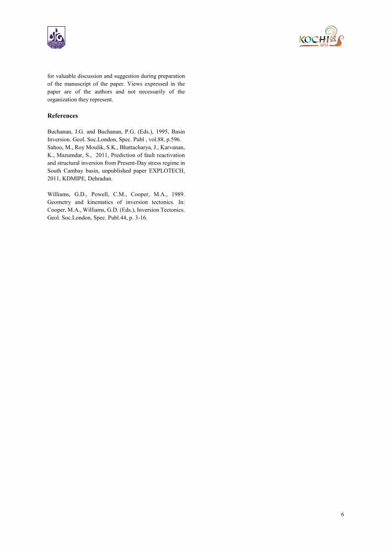
Fig. 8A Narmada Section showing amount of extension and
contraction for calculation of Rhi
Discussion of inversion degrees
Both fault inversion and horizontal inversion ratios have
been identified in South Cambay basin (Table 1). The
magnitudes of extension and thickness changes of syn-rift
deposits in the foot wall and hanging wall contribute
significantly towards the inversion style and the degree of
inversion. Rfi represents the ratio of compressional
reverse slip and normal separation by extension along a
fault, while Rhi represents the relative contractional versus
extensional deformation. Structure with similar amount of
extension produced an inversion ratio with Rfi of 0.36 and
Rhi of 1.28, where contraction and thickness variation are
larger and inversion ratio with Rfi of 0.30 and Rhi of 0.45
where contraction and thickness variations are smaller.
Under simillar geological conditions, inversion structures
having more shortening during inversion, will show higher
horizontal inversion ratio as well as higher fault inversion
ratio. The fault accommodates most of the shortening in
fault reactivated inversion, where as folding
accommodates all the shortening in cover folded inversion.
The Sedimentary facies and thickness changes across
faults, orientation of structures prior to inversion and their
relation to compressive stress field have significant
influence on the inversion and inversion degrees.
Fig. 8B Broach Section showing amount of extension and
contraction for calculation of Rhi.
In fault reactivated inversion with little folding, the two
ratios are direct proportional to each other. As observed in
cover folded inversion, all the shortening has been
accommodated by folding and the reactivated faults
contribute little for determining inversion ratio. Hence the
horizontal inversion ratio represents the true inversion
degree in cover folded inversion.
Conclusion
Two inversion styles, namely fault reactivated and cover-
folded inversions have been recognised in South Cambay
basin. The cover-folded inversions are observed in Broach
Section in which the normal faults are inactive during
inversion. Hence the geometry of cover-folded inversion
has been controlled by strike slip movement of deep seated
faults in the basement. The fault reactivated inversions as
observed in Narmada Section, where all shortening is
accommodated by reverse dip-slip components along pre-
existing normal faults. Hence the geometry of inversion is
controlled by amount of contraction. The timing of
hydrocarbon migration and reactivation of faults forming
inversion structures have a profound effect on
prospectivity of the area.
Acknowledgement
The author wish to thank Director (Exploration) and
GGM-HOI, KDMIPE, Dehradun for permitting the
presentation and publication of this paper. The author is
also thankful to Shri C.Mahapatra, GM (Geol), KDMIPE
6
for valuable discussion and suggestion during preparation
of the manuscript of the paper. Views expressed in the
paper are of the authors and not necessarily of the
organization they represent.
References
Buchanan, J.G. and Buchanan, P.G. (Eds.), 1995, Basin
Inversion. Geol. Soc.London, Spec. Publ , vol.88, p.596.
Sahoo, M., Roy Moulik, S.K., Bhattacharya, J., Karvanan,
K., Mazumdar, S., 2011, Prediction of fault reactivation
and structural inversion from Present-Day stress regime in
South Cambay basin, unpublished paper EXPLOTECH,
2011, KDMIPE, Dehradun.
Williams, G.D., Powell, C.M., Cooper, M.A., 1989.
Geometry and kinematics of inversion tectonics. In:
Cooper, M.A., Williams, G.D. (Eds.), Inversion Tectonics.
Geol. Soc.London, Spec. Publ.44, p. 3-16.