structural engineering and fire dynamics: advances at the interface
TRANSCRIPT
Structural Engineering and Fire Dynamics: Advances at the Interface and Buchanan’s Challenge
ANGUS LAW1, JAMIE STERN-GOTTFRIED1,2, MARTIN GILLIE2, and GUILLERMO REIN2 1Arup, UK 2BRE Centre for Fire Safety Engineering The University of Edinburgh, UK
ABSTRACT
In 2008, Buchanan identified a necessary prerequisite for the advancement of structural fire engineering. He stated that “fire engineers and structural engineers need to talk to each other”. In an attempt to address this need, the following paper provides a historical context of structural fire engineering and presents the results of research conducted when fire engineers and structural fire engineers do, indeed, talk to one another and work together on the same problem. The fire engineering approach is that developed by Stern-Gottfried and Rein using travelling fires to capture realistic fire dynamics in a large compartment, and the structural fire approach by Law and Gillie on the whole frame behaviour of a concrete building. These techniques are not the only approaches, nor are they the ultimate product of Buchanan’s challenge. However, they show how a rational approach to both fire engineering and structural engineering can provide design tools that would be meaningless or impossible otherwise.
KEYWORDS: travelling fires, finite element analysis, reinforced concrete, structural utilization.
INTRODUCTION
Structural fire engineering has travelled a long way since its birth in the 1800s. What began in a few isolated centers quickly bloomed with the First International Fire Congress in 1903 [1]. Research and industrial application proliferated and, over the course of the twentieth century, our level of understanding exploded. Phenomena were discovered and described; structures were tested and improved; standards were written and applied. However, as our comprehension has increased, so has what we demand from our engineers. As we move further into the realm of performance-based design, it is vital that we retain our accumulated knowledge; however, it is also imperative that we are not afraid to question what has come before.
This paper is divided into three sections: firstly, a discussion of the historical context of structural fire engineering; secondly, existing techniques (for both fire and structure) are critically discussed and alternatives are proposed; finally, a combined structural fire analysis is conducted and there is a discussion of how by working together, and aiming for a ‘consistent level of crudeness’ [2], the practice of structural fire design can be improved.
STRUCTURAL ENGINEERING – FIRES AND FAILURE
For any engineering approach to be evaluated fairly, it is necessary to understand not only the technicalities of the method, but also the logic behind its development. This context allows one to judge the technique’s appropriateness for the task at hand; if a different technique is more suitable, then this can be used instead. In the field of structural fire engineering, many of the approaches applied today have their roots at the very beginning of the twentieth century. To understand current design approaches properly, it is necessary to trace the background to technical advances, and the motivations that drove them.
It is documented that the testing of structural assemblies in fire dates back to the late 1800s [3]. As construction techniques became more advanced and multi-storey buildings became more common, designs moved away from traditional all masonry arches to more complex forms. The super-structures of buildings were increasingly composed from a frame of iron members. Floors, meanwhile, began to be constructed from smaller masonry arches sprung from iron beams [3]. Initially, the aim of many fire tests was to establish, through experiment, the relative merits of the products created by competing patent holders.
FIRE SAFETY SCIENCE-PROCEEDINGS OF THE TENTH INTERNATIONAL SYMPOSIUM, pp. 1563-1576 COPYRIGHT © 2011 INTERNATIONAL ASSOCIATION FOR FIRE SAFETY SCIENCE / DOI: 10.3801/IAFSS.FSS.10-1563
1563

Many different organizations throughout Europe and the USA are documented as having conducted fire tests on assemblies such as walls, floors, columns and doors [4].
Standard Testing
The first concerted efforts at fire resistance testing occurred towards the end of the 19th century. In Germany, column tests were conducted in the 1880s and work continued into the 1890s; the USA testing on columns and floors dates from the 1890s. In the UK, the first concerted efforts at fire resistance testing were published by Edwin Sachs [3] in 1899. Sachs is of particular note, as his role in the field of fire testing is significant, but his role is also significant in the field of reinforced concrete design [5] and structural engineering in general. In 1897, he founded the British Fire Prevention Committee (BFPC) which undertook a series of tests on floor assemblies in purpose built masonry ‘huts’. Over the course of the testing programme, the procedure became somewhat standardized. In 1903, the BFPC issued a standard on the classification of protection. This included minimum temperatures for the tests; required loading for some assemblies; and resistance duration requirements [4]. Though this standard became recognized in many countries, engineers in the USA opted to create their own standard.
After the death of Sachs in 1919 testing in the UK did not progress significantly; the BFPC ceased to function in 1924 [6]. Since 1906, the Fire Officers Committee (FOC) had been using a testing facility in Manchester. In 1929, The Royal Institute of British Architects (RIBA) moved this testing station to Borehamwood. In this intermediate period, most testing was ad hoc and occurred at sponsors’ premises or at fire stations. However, during this time, the progress of standardization was gathering pace in the United States.
A new standard produced by the National Fire Protection Association (NFPA) saw the introduction of the first temperature-time curve in 1917; it was based on the idealization of a number of other curves and was closest to a curve which had resulted from a number of wood stoked tests in New York in 1902. The initial rate of temperature increase was made higher to account for the recent introduction of gas or oil fired furnaces. A notable feature of this early standard was the provision that an assembly should be tested for 25 % longer than the required period [4]. The first tests which systematically attempted to measure the temperatures in the furnace were conducted under the supervision of Simon Ingberg from the National Bureau of Standards [3] in 1922. It was recognized by Ingberg that the new standard curve had limitations. He understood that it did not represent a fire, let alone a ‘real’ fire situation. He also recognized though that to subject every assembly that required a fire rating to a whole series of more realistic curves would be prohibitively expensive. Ingberg introduced the concept of ‘fire severity’ whereby the different temperature-time curves could be compared using the equal area concept. Using this technique, Ingberg hypothesised that it was the integral of the fire curve that was important, not the shape of the temperature-time curve. Ingberg remained at the Bureau for some 40 years, and his hypothesis lives on to the present day. It remains unconfirmed but is still used to give fire ratings to assemblies exposed to ‘natural’ fires.
In the UK, meanwhile, the RIBA had recognized that variation in bylaws and lack of proper definitions was leading to misunderstandings and confusion in fire testing. It was proposed, therefore, to draft a suitable standard. After the consideration of a number of curves, it was eventually decided to adopt a curve similar the USA standard. The differences stem from the definition of temperature as a function of time rather than a graphical representation of temperature-time. This standard was published as BS 476 in 1932 and has since been incorporated into the Eurocodes and ISO standards [7].
The standard fire remained largely unchallenged until the 1970s when Pettersson [8] introduced ‘natural’ fire curves in the, so called, Swedish curves. These temperature-time curves were developed to account for the contemporary state-of-the-art of fire dynamics, namely the effect of ventilation, fuel load and the thermal inertia of wall linings on the compartment temperature. Thus, the temperature in the compartment was dependent on the fuel load, openings and wall lining materials of the compartment. As the solutions were implicit, the curves were given in tabular or graphic form; a number of curves were given for different fuel loads and opening factors. As with the standard fire, the curves were incorporated into the Eurocodes. This is discussed in greater detail below.
1564
Since the inception of the first standard fires, fire testing on assemblies of elements has continued using the same methodology. Elements are given fire ratings of half hour intervals based on the amount of time that element is said to have survived a fire [9]. The failure criterion varies depending on the type of assembly that is being tested. Horizontal load bearing elements are normally defined as having failed when some deflection criterion has been met; vertical elements are said to have failed when they can no longer support the applied load. There are also integrity criteria which are designed to prevent the spread of smoke or fire. These criteria are equally applicable to both load bearing and non-load bearing elements.
Moving Away From Standard Testing
In the UK from 1946, a fire grading system was introduced [10]. The aim of this was to safeguard life-safety and property. This system gave the required fire resistance ratings (according to BS 476) for different building occupancies and was generally regarded as being successful in its aim [11]. However, the economic rationality of fire protecting public and office buildings and the proportionality of the cost with respect to other aspects of safety was questioned [12].
During the 1970s, the desire to reduce or eliminate fire protection from steel structures led architects and engineers to find justifications for removing protection based on how the structure performed and the wider context of the building. Some of the earliest examples of this performance-based design include the Royal Exchange, Manchester, and the Pompidou centre, Paris [13]. These projects reasoned that fire protection could be omitted without additional danger to occupants or the fire-service and, in the case of the Pompidou centre, the main columns were filled and cooled with water to allow the omission of external protection [13]. At this time, however, there was resistance to the introduction of fire safety engineering into structural fire design; this was both from structural engineers and regulators [14]. It was, though, recognized that the procedure of standard fire testing was both unreliable (as discussed below) and expensive [15]. It was also thought that one of the limitations of the standard fire test was that it did not take into account the behaviour of the whole structure and that this could lead to failure of elements in real fires which passed the standard fire test [11]. As a consequence of these concerns, there was a move towards analytical structural fire engineering methods; alternative approaches to obtaining fire ratings were sought [16]. This was the driver that lead to the development of the performance based design techniques and computer analysis software which we use today.
Towards Whole Frame Behaviour
In the early hours of June 23rd 1990, a major fire occurred at 14 storey office building in Bishopsgate, London. The building was in the final stages of construction and although most of the partition walls and fire protection was fitted, sections of column protection were not present at the seat of the fire. The fire began in a sub-contractors hut on the first floor and caused extensive damage to the first and second floors. The fire was deemed to have burnt severely for two and a half hours with a total duration of four and a half hours. There were no casualties, but £25m (US$40m) of damage was caused; of this, only £2m (US$3.2m) was structural damage [17].
The performance of the structure was considered to be satisfactory as there was no collapse, and adjoining property remained safe. Indeed, as the first fire of its kind [18], Broadgate revealed the degree to which whole structural frame could contribute to structural performance during a fire; it also showed that the single member approach to fire safety design was non-rational and over-conservative [19]. The relatively good performance of Broadgate, and the non-inclusion of the phenomena observed in design practices of the time led to a new phase in structural fire research.
In response to Broadgate and in an attempt to better understand how the structure had behaved, a series of large-scale fire tests were conducted at the Building Research Establishment’s (BRE) testing facility at Cardington. Fire testing had been conducted at this facility since 1970 [6], and by the early 1990s, there were 14 permanent rigs established. Three large scale structures were built at Cardington, the first was an eight storey composite steel structure completed in March 1993; the second was a timber framed structure; and the third a concrete frame.
1565

The design of the steel test (both the structure, and fires to which it was subjected) were significantly influenced by Broadgate [20]. During 1995 and 1996, a series of six tests were conducted on different parts of the structure. Over the course of the various tests, it was found that steel temperatures in some locations exceeded 1100 ºC with no collapse occurring. Traditional design methods would have defined failure at approximately 680 ºC; this emphasized the difference between the behaviour in a standard test and in a real structural assembly.
A significant amount of computer modeling work was conducted on the Cardington steel frame tests. Initial modeling attempts were generally successful; however, many simplifying assumptions were made [21]. As techniques became more advanced, the number of simplifying assumptions was reduced. Non-linear material and geometric effects were included in finite-element models developed by researchers at Sheffield, Manchester, Edinburgh, and Imperial Universities [22–25].
The Cardington tests and the computer models definitively demonstrated that composite action of a whole structure could dramatically improve performance during a fire. As the beams were heated, the slab began to act as a tensile membrane [26]. This change in behaviour caused the slab to perform better than it would have done if bending was the dominant mechanism: large deflections were achieved without loss of stability or compartmentation. Together, Broadgate and Cardington demonstrated that the single-element, standard testing approach was both inadequate in terms of understanding ultimate performance, and was over conservative. The experiments, in conjunction with some additional testing [27], resulted in the development of new design tools and guidance [26].
In 1998, a similar sized concrete frame was also constructed at Cardington. The frame was intended for use in analysing the performance of various aspects of construction and the performance of the structure. One aspect of the study was the response of the structure to fire. However, due to the imminent closure of BRE’s Cardington facility, the experimental setup and testing was conducted hastily in the late summer of 2001 [28]. In comparison with the steel test, a relatively small amount of subsequent analysis was conducted.
Though the full scale Cardington test represented a step change in the approach of researchers and engineers with regard to the behaviour of structures in fire, it also represents the zenith of large scale structural fire testing to-date. Subsequently, there have been whole frame tests, but they have generally been much smaller experiments [29, 30].
Towards Performance-Based Design
The net result of these developments is that design philosophies and engineering techniques in connection with structures in fire have begun, and continue, to change. The conventional methods of prescriptive design had become an obstacle in the drive for more advanced and efficient structures. The mid-1990s saw the introduction of performance-based design in many countries around the world [31]. This allowed engineers to design structures to meet performance requirements rather than to follow a prescribed set of rules for each structural assembly. For example, design codes such as the Eurocodes allow engineers a high degree of flexibility in the way they design structures. Prescriptive design remains acceptable, but if they wish, engineers may use more advanced approaches such as calculation methods or finite-element modelling to demonstrate that a structure is able to perform adequately in a fire.
FIRE AND STRUCTURE – A CONSISTENT LEVEL OF CRUDENESS
So far this paper has discussed the methods that are used to characterize and evaluate how isolated structures might perform upon strong heating. However, little attention has been paid to how suitable these methods are to understand true fire performance of a building and the future of design. Moreover, the complexity (or, perhaps, crudeness) of the methods described varies significantly. This section identifies where these mismatches in complexity occur, and presents alternative methods which achieve a more ‘consistent level of crudeness’ [2].
1566
The Fire
The current parametric and standard fires are based on the extrapolation of existing fire test data, which stem from tests performed in small compartments (typically less than 3 m on any one side) that are almost cubic in nature. This test geometry allows for good mixing of the fire gases and full contact with the walls, thus it was hypothesized that a uniform temperature distribution throughout the compartment was reached. This hypothesis has recently been tested. The results of this work demonstrate that uniform temperature conditions are not present and large variation exists [32].
Limitations of the Standard Fire
The standard fire temperature-time curve [9] was created in an attempt to regulate testing between different laboratories thereby ensuring a uniform standard of safety. However, almost as soon as it was conceived, a number of problems were identified with it. These problems were both in terms of the implementation of the test, and the fundamental approach to testing. For example, though the aim of every test was to impose the standard fire curve, variations between furnaces, temperature control systems, and fuel type, led to significant differences between results at different laboratories. Careful standardization has resolved many of these issues, but fundamental problems still remained.
For example: • The testing of assemblies in isolation means that the interaction of elements with the surrounding
structure is not represented or understood; • An assembly can be tested any number of times until it achieves the required fire rating; • Unlike the original standard, an assembly only needs to achieve the required time to obtain a rating (an
assembly that failed after 1 hr and 1 s would achieve the same rating as an assembly that failed after 1 hr 29 min and 59 s);
• The furnace and standard curve do not take into account the material that is being tested. For example, if the surface of the test assembly has a very high thermal inertia, then less fuel will be required to achieve the required temperature in the compartment at any given time.
• The actual heating of the element being tested is affected by the net heat flux to it, thus making the test results dependant on the lining materials and geometry of the furnace itself, which is not consistent across all test facilities.
Limitations of Parametric fires
The Swedish curves developed by Petterson were expressed in graphical format. Wickström [33,34] aimed to collapse all of Pettersson’s temperature-time curves into a single explicit mathematical form. He did this by introduction of a modified time parameter and the mathematical form of the standard fire as it was expressed in the Swedish building code at the time. The time parameter is normalised with a specific ventilation opening (a single door sized opening in a room roughly 3 m on each side) and wall lining material (an average value of different concretes and brick).
This work led to the parametric fires given in Eurocode 1 [35]. Franssen [36] then proposed modifications to the Eurocode parametric temperature-time curve to better correlate with predicted peak temperatures from 48 experiments. The Eurocode was adjusted in the 2002 edition to account for this, and consequently severed its links with it earlier theoretical basis from Petterson.
The cooling phase of the natural fire curves are based on simplistic assumptions. Pettersson et al assumed a cooling rate of 10 °C per minute, but note that it “must be regarded as very unsatisfactory that different parts of the same fire process should be described with entirely different accuracy.” While slight modifications to the cooling rate have subsequently been made in the development of the Eurocode parametric temperature-time curve, they still amount to a set of simplistic assumptions and do not explicitly calculate it.
1567

Though they are significantly closer to real fire behaviour than the standard fire, parametric fires also have serious limits on their range of applicability. For example, Eurocode 1 states that the design equations are only valid for compartments with floor areas up to 500 m2 and heights up to 4 m, the enclosure must have no openings through the ceiling, and the compartment linings are also restricted to a thermal inertia between 1000 and 2200 J/m2·s½·K, which means that highly conductive linings such as glass facades and highly insulating materials cannot be taken into account. The origin of these limitations are not clear, but they are thought to stem from inherent limitations of testing in small enclosures [37]. As a result, common features in modern construction like large enclosures, high ceilings, atria, large open spaces, multiple floors connected by voids, and glass facades are excluded from the range of applicability of the current methodologies.
Parametric fires, though, represent a more realistic scenario than the standard fire as they assume burn-out of the available fuel. However, as discussed previously, burn-out fires are often related to the standard fire using equal area the concept of ‘fire severity’ [38]. This idea has no physical basis and was criticized by Harmathy and Mehaffey [39] as far back as 1982, yet has still become embedded into the common approach to structural fire engineering [7].
General Limitations
An assumption that has remained unquestioned with each of these temperature-time curves has been that of uniform compartment temperature. It is assumed that every part of a structural element or compartment is uniformly subject to the same temperature – as defined by the temperature-time curve. Although it may be possible to replicate these conditions in a furnace, recent major fires at the Windsor Tower, World Trade Centers, and TU-delft have clearly demonstrated that building fires typically burn non-uniformly. They have shown that fires tend to move around buildings in a manner determined by the available fuel, ventilation and building geometry. In addition, tests have shown that there is a high degree of temperature variation even within small compartments [40].
Limitation of Crudeness
When the fire design of a structure was based on the furnace testing of a single element, both the structural member and the temperature-time curve were gross simplifications of reality. In recent years the representation of structure, though not perfect, has often become much more realistic; design fires, however, have remained unchanged. It is difficult to reconcile the complexity of the two approaches in seeking the consistent level of crudeness that is required for pragmatic design.
Updating the Design Fire
This section presents an alternative methodology for defining design fires. The approach is founded on the basics of fire dynamics, and allows for the development of different temperatures in different parts of fire a compartment – the key phenomenon missing from existing models. Fundamental to the new approach is the idea of the travelling fire that has consistently been observed in real accidental fires. Also key to this approach is the requirement for the fire engineer and the structural fire engineer to work together to create the most appropriate design fire. The approach has been developed by researchers and practitioners at The University of Edinburgh and Arup [40] and its influence on structures has begun to be studied.
The new approach uses two different temperatures to represent gas temperatures in a fire compartment: a local and high temperature in the region of the seat of the fire, which is considered to travel within a compartment as fuel is consumed; and a cooler temperature for the rest of the compartment. By allowing the size of the fire to be varied this approach provides a flexible technique whereby a range of possible fires can be represented. For example, a fire which engulfs an entire floor plate simultaneously can be represented. Likewise, a small fire that travels from one end of a compartment to the other can also be defined. Rather than basing the type of fire on predicted factors such as glazing breakage, the burn area of the fire is directly specified by the fire engineer. As such, different fires can be created without artificially manipulating the physical input parameters.
1568
Temperature Definition
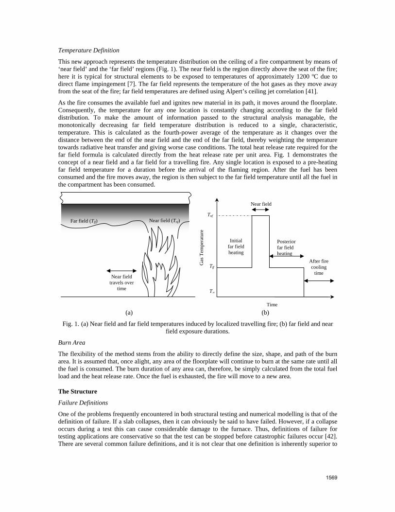
This new approach represents the temperature distribution on the ceiling of a fire compartment by means of ‘near field’ and the ‘far field’ regions (Fig. 1). The near field is the region directly above the seat of the fire; here it is typical for structural elements to be exposed to temperatures of approximately 1200 ºC due to direct flame impingement [7]. The far field represents the temperature of the hot gases as they move away from the seat of the fire; far field temperatures are defined using Alpert’s ceiling jet correlation [41].
As the fire consumes the available fuel and ignites new material in its path, it moves around the floorplate. Consequently, the temperature for any one location is constantly changing according to the far field distribution. To make the amount of information passed to the structural analysis managable, the monotonically decreasing far field temperature distribution is reduced to a single, characteristic, temperature. This is calculated as the fourth-power average of the temperature as it changes over the distance between the end of the near field and the end of the far field, thereby weighting the temperature towards radiative heat transfer and giving worse case conditions. The total heat release rate required for the far field formula is calculated directly from the heat release rate per unit area. Fig. 1 demonstrates the concept of a near field and a far field for a travelling fire. Any single location is exposed to a pre-heating far field temperature for a duration before the arrival of the flaming region. After the fuel has been consumed and the fire moves away, the region is then subject to the far field temperature until all the fuel in the compartment has been consumed.
(a) (b)
Fig. 1. (a) Near field and far field temperatures induced by localized travelling fire; (b) far field and near field exposure durations.
Burn Area
The flexibility of the method stems from the ability to directly define the size, shape, and path of the burn area. It is assumed that, once alight, any area of the floorplate will continue to burn at the same rate until all the fuel is consumed. The burn duration of any area can, therefore, be simply calculated from the total fuel load and the heat release rate. Once the fuel is exhausted, the fire will move to a new area.
The Structure
Failure Definitions
One of the problems frequently encountered in both structural testing and numerical modelling is that of the definition of failure. If a slab collapses, then it can obviously be said to have failed. However, if a collapse occurs during a test this can cause considerable damage to the furnace. Thus, definitions of failure for testing applications are conservative so that the test can be stopped before catastrophic failures occur [42]. There are several common failure definitions, and it is not clear that one definition is inherently superior to
Far field (Tff) Near field (Tnf) Tnf
Tff
Initial far field heating
Posterior far field heating
T∞
Near field G
as T
empe
ratu
re
After fire cooling
time Near field
travels over time
Time
1569
another. The measures stem from historic structural testing procedures or from known material properties. They are frequently now applied not just to testing the performance of real structures, but also to the design of structures to resist fire. Finite-element models make it very easy to measure each of the indicators described below. Consequently, engineers can use one (or multiple) definitions to identify strengths and weaknesses in their designs.
Maximum deflection is frequently used as a failure criterion. Failure is typically defined as a ratio of deflection (e.g. span/20 [9]). This definition is not strictly one of stability loss but rather a useful, if rather arbitrary, definition by which the performance of a structure can be measured and the testing furnace protected. The tests at Cardington demonstrated that deflections significantly in excess of this limit can occur without any loss of stability.
In steel structures the temperature of columns or beams is often used as an indication of failure. For concrete structures, this translates to the temperature of the tension reinforcement. A limiting temperature is given and if the steel rises above this temperature, failure is said to have occurred. This, binary, approach to structural performance (either failed, or not failed) does not adequately capture the processes that occur in real structures. Single elements failure is often a complex process, and when the possibility of load redistribution is introduced, limiting temperature in one location does not necessarily correspond to collapse.
In concrete structures or slabs, the rupture strain in steel reinforcement is often used as a basis for a failure criterion. Typically this measure is better suited to the numerical analysis of structures rather than fire tests because of the difficulties associated with instrumentation of rebar. The ultimate strain for steel at any temperature is usually taken as 0.2 [43].
Updating the Structural Approach
The failure definitions described previously are useful methods for measuring how a structure performs in a fire. However, in the context of finite-element modeling, they rely on a relatively small proportion of the available information about the structure. For example, temperatures at certain locations are used to diagnose the performance of the entire structure. Utilization is frequently used in elastic design to determine how efficiently a structure is designed, and where improvements can be made.
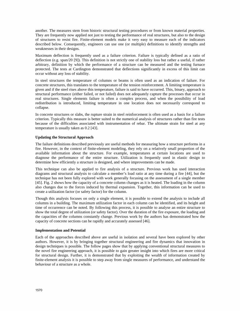
This technique can also be applied to fire analysis of a structure. Previous work has used interaction diagrams and structural analysis to calculate a member’s load ratio at any time during a fire [44], but the technique has not been fully explored with work generally focusing on the assessment of a single member [45]. Fig. 2 shows how the capacity of a concrete column changes as it is heated. The loading in the column also changes due to the forces induced by thermal expansion. Together, this information can be used to create a utilization factor (or safety factor) for the column.
Though this analysis focuses on only a single element, it is possible to extend the analysis to include all columns in a building. The maximum utilization factor in each column can be identified, and its height and time of occurrence can be noted. By following this process, it is possible to analyse an entire structure to show the total degree of utilization (or safety factor). Over the duration of the fire exposure, the loading and the capacities of the columns constantly change. Previous work by the authors has demonstrated how the capacity of concrete sections can be rapidly and accurately assessed [46].
Implementation and Potential
Each of the approaches described above are useful in isolation and several have been explored by other authors. However, it is by bringing together structural engineering and fire dynamics that innovation in design techniques is possible. The follow pages show that by applying conventional structural measures to the novel fire engineering approach, it is possible to gain greater insight into which fires are more critical for structural design. Further, it is demonstrated that by exploiting the wealth of information created by finite-element analysis it is possible to step away from single measures of performance, and understand the behaviour of a structure as a whole.
1570
(a) (b)
Fig. 2 (a) Change in capacity in a concrete column over the duration of a fire, the loading to which the column is subjected continually changes as the fire develops; (b) utilization of column as fire develops.
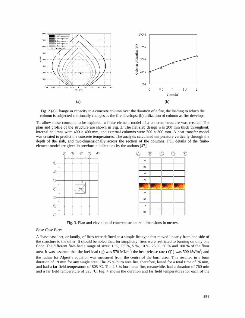
To allow these concepts to be explored, a finite-element model of a concrete structure was created. The plan and profile of the structure are shown in Fig. 3. The flat slab design was 200 mm thick throughout; internal columns were 400 × 400 mm, and external columns were 300 × 300 mm. A heat transfer model was created to predict the concrete temperatures. The analysis calculated temperature vertically through the depth of the slab, and two-dimensionally across the section of the columns. Full details of the finite-element model are given in previous publications by the authors [47].
Fig. 3. Plan and elevation of concrete structure, dimensions in metres.
Base Case Fires
A ‘base case’ set, or family, of fires were defined as a simple fire type that moved linearly from one side of the structure to the other. It should be noted that, for simplicity, fires were restricted to burning on only one floor. The different fires had a range of sizes: 1 %, 2.5 %, 5 %, 10 %, 25 %, 50 % and 100 % of the floor area. It was assumed that the fuel load (qf) was 570 MJ/m2; the heat release rate ( Q ′′ ) was 500 kW/m2; and the radius for Alpert’s equation was measured from the centre of the burn area. This resulted in a burn duration of 19 min for any single area. The 25 % burn area fire, therefore, lasted for a total time of 76 min, and had a far field temperature of 805 ºC. The 2.5 % burn area fire, meanwhile, had a duration of 760 min and a far field temperature of 325 ºC. Fig. 4 shows the duration and far field temperatures for each of the
1571

base case fires. It should be noted that for the 100 % area fire, the far field temperature is the same as the near field temperature.
Fig. 4. Far field temperatures and durations for different burn area fires. Standard and parametric fire
curves are also shown for reference.
Basic Measures
The behaviour of the slab in every bay was monitored using two of the basic measures of performance as described above (temperature and defection). Over the duration of the fire, the most extreme behaviour was observed in the final bays to be exposed to the near field. For each base case fire, the maximum value obtained from each measure was recorded. These are plotted in Fig. 5. It can be clearly seen that the fires of medium duration induce the most extreme behaviour in the structure. The 25 % burn area, 76 min fire, causes the highest temperatures and the largest deflections.
(a) (b)
Fig. 5. Change in structural distress with burn area: (a) rebar temperature, standard fire equivalent is 1 hr 37 min; (b) deflection, standard fire equivalent is 1 hr 54 min.
Using these simple measures, it is possible to draw conclusions about which size of fire is most critical for a structure. Additional comparisons are possible by comparing travelling fires to standard and parametric fires. It can be seen that in most cases, the travelling fire induces more extreme structural behaviour than parametric fires. The temperature results indicate that the 25 % burn area fire is equivalent to a 1 hr 37 min standard fire. The deflection results indicate that the same travelling fire is equivalent to a 1 hr 54 min standard fire. This further illustrates that the equal-area approach as a measure of time equivalence does not reliably represent how the structure performs.
1572

Advanced Measures
The utilization approach described above allows a much large set of available data to be used in the interpretation of the results. Rather than analyzing the slab, the loading in each part of every column in the building was recorded. This was then compared to the pre-calculated column capacity based on the material behaviour and temperature profile. For brevity, this paper will only describe the utilization analysis in terms of axial force and moment. However, it should be noted that it is also possible to analyze shear utilization in a similar manner [48]. Previous work by the author describes the how the interaction surfaces used in these analyses were derived [46].
Analyses such as these allow a much more complex picture of structural behaviour to be created. Analysis of a single fire scenario can provide a level of utilization for each element in a structure. Members that are vulnerable to failure can be identified, as can those which are over-engineered. However, the structural measures in Fig. 5 indicate that different fires induce varying levels of distress within the structure. When multiple fires are applied to a structure, the utilization approach allows an envelope of behaviour to be created. The fire engineer can identify the credible scenarios, and the structural fire engineer can derive the envelope of behaviour.
This process was completed for multiple fire scenarios. In addition to the ‘base case’ described above, alternative paths of fire travel were considered (for example, clockwise around the central core, or gradually outwards from the centre). This allowed the structure’s fire behaviour envelope to be developed as shown in Fig. 6. This figure shows the maximum, minimum and mean utilization that each column was subjected to over the full duration of every fire.
From information such as this, it is possible to draw general conclusions about how the structure is performing in fire. For example, it is clear that particular columns are very highly utilized in some fire scenarios. In contrast, some columns show very low levels of utilization. Designs can be adjusted accordingly.
0%
10%
20%
30%
40%
50%
60%
70%
80%
90%
100%
A7 B6 E7 D6 A6 E6 D7 D2 B2 B7 C7 A2 D1 E2 A1 E1 B1 E5 A5 C1 E3 A3 D5 B5 D3 A4 B3 E4 B4 D4 C6 C2 C3 C5Column Name
Util
izat
ion
Minimum
AverageMaximum
Fig. 6. Average, maximum and minimum utilization rates for each column subject to multiple fire
scenarios.
The method of combining utilization information from all of the different fires is analogous to the approach taken when designing structures against imposed load at ambient temperatures. At ambient temperature the shears and moments that are induced by different combinations of imposed loads (for example, on alternate spans) are calculated, and the structure is designed to resist the entire envelope of possible load cases. In the case of the structure above in fire, a number of realistic design fires were applied and the response of the frame to each one was analysed individually. This is a more thorough approach than just applying one fire curve, such as the standard or a parametric fire, to a structure, which is, perhaps, equivalent to applying full imposed and dead load and simply designing the structure on that basis while ignoring other mechanical loading scenarios.
Of course, it would be possible to consider multiple parametric fires in design and take these as different load cases. However, this would again introduce a substantial mismatch in the level of complexity between the fire engineering approach and the structural engineering techniques employed. In the context of
1573

structural analysis, it is worth reconsidering the factors that make robust fire dynamics so essential if advanced structural fire engineering is to be adopted:
• If the standard fire curve represents the most extreme set of fires to which a structure can be subjected, then the equivalent in ambient design would be specifying a structure to resist all different mechanical loads at the same time acting at their peak values and would result in an unacceptably conservative design. Moreover, this would also be equivalent to designing a planned residential space to resist the loading that would be imposed by an industrial storage area; this degree of future proofing would also be unacceptably inefficient for an initial structural design.
• If the aim of design is to create the most efficient structure, then the use of a family of fires based on fire dynamics allows optimization in the same way as structures are optimized for different loadings at ambient design.
CONCLUSIONS
This paper has shown how, by working together, fire engineers and structural fire engineers have produced innovative design tools in both historic and contemporary contexts. In fire engineering, there is often very little consideration of which fire will be the most critical for structural design. Likewise, structural fire engineers use a temperature-time curve as a starting point and then tend to focus on the structural analysis. The overlap between the two disciplines has allowed a more realistic set of fire scenarios to be developed, and enabled a more robust approach to the structural analysis to be implemented. Additionally:
• The introduction of fire engineering techniques into the realm of structural fire design addresses a mismatch in complexity that exists between structural fire engineering and its thermal inputs;
• The implementation of utilization analysis across a whole building addresses the mismatch between the techniques used to model structures, and the measures used to assess them.
ACKNOWLEDGEMENTS
The authors would like to acknowledge BRE Trust for sponsoring this project. Arup are also gratefully acknowledged for their financial support.
REFERENCES
[1] Wilmore, D., Edwin O Sachs; Architect, Stagehand, Engineer and Fireman, Theatresearch, Summerbridge, 1998.
[2] Buchanan, A., (2009) The Challenges of Predicting Structural Performance in Fires, Fire Safety Science 9: 79-90, http://dx.doi.org/10.3801/IAFSS.FSS.9-79.
[3] Babrauskas, V., and Williamson, R.B., (1978) The Historical Basis of Fire Resistance Testing — Part I, Fire Technology 14: 184-194, http://dx.doi:10.1007/BF01983053.
[4] Babrauskas V., and Williamson R.B., (1978) The Historical Basis of Fire Resistance Testing — Part II, Fire Technology 14(4): 304-316, http://dx.doi.org/10.1007/BF01998390.
[5] Chrimes, M., Sutherland, J., and Humm, D., (eds.). Historic Concrete: The Background to Appraisal. London, Thomas Telford, 2001.
[6] Read, R.H.H., A Short History of the Fire Research Station, Borehamwood, BRE, Garston, 1994.
[7] Drysdale, D., An Introduction to Fire Dynamics, Wiley, Chichester, 1998.
[8] Pettersson, O., Magnuson S.E., and Thor J., Fire Engineering Design of Structures, Publication 50: Swedish Institute of Steel Construction, 1976.
[9] BS476-20:1987, Fire Tests on Buildings Materials and Structures - Part 20: Method for Determination of the Fire Resistance of Elements of Construction, BSI, 1987.
[10] Fire Grading of Buildings, Part I, H M Stationary Office, 1946.
1574

[11] Law, M., (1986) Translation of Research into Practice: Building Design, Fire Safety Science 1: 603-609, http://dx.doi.org/10.3801/IAFSS.FSS.1-603.
[12] Future Fire Policy, a Consultative Document, H M Stationary Office, London, 1980.
[13] Law, M., Designing Fire Safety for Steel - Recent Work, ASCE Spring Convention, New York, USA: American Society of Civil Engineers, 1981.
[14] Law, M., Some Selected Papers by Margaret Law, Arup, London, 2002.
[15] Pettersson, O., and Witteveen, J., (1980) On the Fire Resistance of Structural Steel Elements Derived from Standard Fire Tests or by Calculation, Fire Safety Journal 2(1): 73-87, http://dx.doi.org/10.1016/0379-7112(79)90016-X.
[16] CIB-W14, (1986) Design Guide Structural Fire Safety, Fire Safety Journal 10(2): 75-147, http://dx.doi.org/10.1016/0379-7112(86)90041-X.
[17] Drysdale, D.D., (2001) Special Issue on Response of Composite Steel Framed Structures to Fire, Fire Safety Journal 36(8): 719-720, http://dx.doi.org/10.1016/S0379-7112(01)00043-1.
[18] Structural Fire Engineering Investigation of Broadgate Phase 8 Fire, The Steel Construction Institute, Ascot, Berkshire, 1991.
[19] Lane, B., The Response of Steel Framed Structures under Fire Conditions, PhD: The University of Edinburgh, 1997.
[20] The Behaviour of Multi-Storey Steel Framed Buildings in Fire, British Steel plc, Rotherham, 1999.
[21] Bailey, C.G., Burgess, I.W., and Plank, R.J., (1995) Computer Simulation of a Full-Scale Structural Fire Test, The Structural Engineer 74: 93-100.
[22] Huang, Z., Burgess, I.W., and Plank, R.J., (2001) Non-Linear Structural Modelling of a Fire Test Subject to High Restraint, Fire Safety Journal 36(8): 795-814, http://dx.doi.org/10.1016/S0379-7112(01)00040-6.
[23] Gillie, M., Usmani, A., Rotter, M., and O'Connor, M., (2001) Modelling of Heated Composite Floor Slabs with Reference to the Cardington Experiments, Fire Safety Journal: 745-767, http://dx.doi.org/10.1016/S0379-7112(01)00038-8.
[24] Elghazouli A.Y., and Izzuddin B.A., (2001) Analytical Assessment of the Structural Performance of Composite Floors Subject to Compartment Fires, Fire Safety Journal 36(8): 769-793, http://dx.doi:10.1016/S0379-7112(01)00039-X.
[25] Wang, Y.C., (2000) An Analysis of the Global Structural Behaviour of the Cardington Steel-Framed Building During the Two BRE Fire Tests, Engineering Structures 22(5): 401-412, http://dx.doi.org/10.1016/S0141-0296(98)00127-8.
[26] Newman, G.M., Robinson, J.T., and Bailey, C.G., Fire Safe Design: A New Approach to Multi-Storey Steel Framed Buildings, Steel Construction Institute, Ascot, Berkshire, 2000,
[27] Bailey, C.G., White, D.S., and Moore, D.B., (2000) The Tensile Membrane Action of Unrestrained Composite Slabs Simulated under Fire Conditions, Engineering Structures 22(12): 1583-1595, http://dx.doi.org/10.1016/S0141-0296(99)00110-8.
[28] Bailey, C., (2002) Holistic Behaviour of Concrete Buildings in Fire, Structures and Buildings 152: 199-212.
[29] Lennon, T., Whole Building Behaviour - Results from a Series of Large Scale Tests, CIB-CTBUH International Conference on Tall Buildings, Malaysia, 2003.
[30] Bailey, C.G., and Lennon, T., (2008) Full-Scale Fire Tests on Hollowcore Floors, The Structural Engineer 86: 33-39.
1575
[31] Buchanan, A.H., Structural Design for Fire Safety, Wiley, Chichester, 2006.
[32] Stern-Gottfried, J., Rein, G., Bisby, L.A., and Torero, J.L., (2010) Experimental Review of the Homogeneous Temperature Assumption in Post-Flashover Compartment Fires, Fire Safety Journal 45(4): 249-261, http://dx.doi.org/10.1016/j.firesaf.2010.03.007.
[33] Wickström, U., (1981) Temperature Calculation of Insulated Steel Columns Exposed to Natural Fire, Fire Safety Journal 4(4): 219-225, http://dx.doi.org/10.1016/0379-7112(81)90024-2.
[34] Wickstrom, U., Application of the Standard Fire Curve for Expressing the Natural Fires for Design Purposes, In: Harmathy T.Z., (ed.), Fire Safety: Science and Engineering, Philadelphia: America Society for Testing and Materials, 1985. p.145-159.
[35] ENV1991-2-2, Eurocode 1: Basis of Design and Actions of Structures - Part 2-2: Actions on Structures - Actions on Structures Exposed to Fire, CEN, Brussels, 1995.
[36] Franssen, J.M., 2000. Improvement of the Parametric Fire of Eurocode 1 Based on Experimental Test Results. Fire Safety Science 6: 927-938. http://dx.doi.org/10.3801/IAFSS.FSS.6-927
[37] Stern-Gottfried, J., Rein, G., and Torero, J.L., Travel Guide, Fire Risk Management, 2009, p.12-16, http://hdl.handle.net/1842/3184.
[38] Lennon, T., Hopkin, D., El-Rimawi, J., and Silberschmidt, V., (2010) Large Scale Natural Fire Tests on Protected Engineered Timber Floor Systems, Fire Safety Journal 45(3): 168-182, http://dx.doi.org/10.1016/j.firesaf.2010.02.006.
[39] Harmathy, T.Z., and Mehaffey, J.R., (1982) Normalized Heat Load: A Key Parameter in Fire Safety Design, Fire and Materials 6(1): 27-31, http://dx.doi.org/10.1002/fam.810060108.
[40] Stern-Gottfried, J., Law, A., Rein, G., Gillie, M., and Torero, J.L., A Performance Based Methodology Using Travelling Fires for Structural Analysis, 8th International Conference on Performance-Based Codes and Fire Safety Design Methods, Lund, 2010.
[41] Alpert, R.L., (1972) Calculation of Response Time of Ceiling-Mounted Fire Detectors, Fire Technology 8(3): 181-195, http://dx.doi.org/10.1007/BF02590543.
[42] Kodur, V., Dwaikat, M., and Raut, N., (2009) Macroscopic FEe Model for Tracing the Fire Response of Reinforced Concrete Structures, Engineering Structures 31(10): 2368-2379, http://dx.doi.org/10.1016/j.engstruct.2009.05.018.
[43] EN1993-1-2, Eurocode 3: Design of Steel Structures - Part 1-2: General Rules - Structural Fire Design, 2005.
[44] Garlock, M.E.M., and Quiel, S.E., (2008) Plastic Axial Load and Moment Interaction Curves for Fire-Exposed Steel Sections with Thermal Gradients, Journal of Structural Engineering 134(6): 874-880, http://dx.doi.org/10.1061/(ASCE)0733-9445(2008)134:6(874).
[45] Dwaikat, M., and Kodur, V., (2010) A Simplified Approach for Evaluating Plastic Axial and Moment Capacity Curves for Beam-Columns with Non-Uniform Thermal Gradients, Engineering Structures 32: 1423-1436, http://dx.doi.org/10.1016/j.engstruct.2009.05.018.
[46] Law, A., and Gillie, M., (2010) Interaction Diagrams for Ambient and Heated Concrete Sections, Engineering Structures 32(6): 1641-1649, http://dx.doi.org/10.1016/j.engstruct.2010.02.012.
[47] Law, A., Stern-Gottfried, J., Gillie, M., and Rein, G., (2011) The Influence of Travelling Fires on a Concrete Frame, Engineering Structures 33(5): 1635-1642, http://dx.doi.org/10.1016/j.engstruct.2011.01.034.
[48] Law, A., The Assessment and Response of Concrete Structures Subject to Fire, School of Engineering, PhD, Edinburgh: University of Edinburgh, 2010, http://hdl.handle.net/1842/4574.
1576