structural design analysis software diamonds · structural design analysis software diamonds an...
TRANSCRIPT
Structural DeSign analySiS Software
Diamondsan engineer’S beSt choice
lateral buckling restraint - attaches - steel check - creep - charges climatiques - dynamic analysis - lateral buckling - brandweer-standsanalyse - timber - 1st order - verstijvers - buisverbinding - diseño de planos de armaduras - pandeo lateral - verbindingen
- shear connection - verificación - armatures longitudinales - pórtico - unión base columna - voorontwerp - unión tubular - haunch - con-
nexion moment - cimbras - vérification acier - unity check - Eurocode 2 - mesh - retaining wall - raidisseur - eurocode
3 - longitudes de pandeo - connections - aci - acero - 2nd ordre - portal frame - eurocode 8 - andamios - kip - dwarskracht-verbinding - bS - dalle de fondation - seismische analyse - armaduras longitudinales - BIM - gelaste verbinding - 2de orde - buckling
- funderingszool - poutre sur plusieurs appuis - maillage - malla - uniones - 2D raamwerken - fire resistance analysis - voiles
- cracked deformation - gescheurde doorbuiging - longueurs de flambement - pandeo - reinforcement -
unity check - cantonera - dynamische analyse - hout - ossatures 3D - koudgevormde profielen - placa de extreme - 1er orden
- continuous beam - connexion soudée - momentverbinding - praktische wapening - integrated connection design - ren-
forts au déversement - fluencia - estribos - déformation fissurée - ehe - beugels - eurocódigo 3 - platine de bout - análisis dinámico
- column base plate - kruip - rigid link - welded connection - charpente métallique - AISC - moment connections - estructuras
2D - kniestuk - assemblage métallique - 3D raamwerken - second ordre - beam grid - cargas climáticas - eurocode 2 - eurocode
5 - wall - deformación fisurada - lien rigide - enlace rígido - 2D frames - estructuras 3D - éléments finis - vloerplaat - steel connec-
tion - seismic analysis- scheurvorming - armatures pratiques - analyse sismique - nieve y viento - practical
reinforcement - charges mobiles - dalle - wapening - perfiles conformados en frío - Eurocode 3 - connexion tubulaire - unión a mo-
mento - 3D frames - treillis de poutres - roof truss - practical reinforcement design - portique - kipsteunen - análisis sísmico
- b.a.e.l - uniones atornilladas - bolts - Eurocode 8 - ossatures 2D - eindige elementen - losa de cimentación - restricciones para el pandeo lateral
- optimisation - wand - kniklengtes - end plate - dakspanten - kolomvoetverbinding - stirrups - acier - staalcon-
trole - cálculo de uniones integrado - paroi - dessin du plan de ferraillage - stiffeners - mobiele lasten - eurocódigo 8 - eurocódigo 5 - longitudinal
reinorcement - doorlopende liggers - rigidizador - beton armé - fluage - cte - connexion pied de poteau - langswapening
- connexions - hormigón - neige et vent - elementos finitos - armaduras - cold formed steel - jarret - uittekenen wapening - puente
grúa - analyse dynamique - flambement - keerwanden - optimisation - steel - cercha - 2º orden - slab on grade foundation - entramado de vi-
gas - Eurocode 5 - prédimensionnement - multi span beam - bouten - armatures - floor slab - poutre continue - pared - staal - 1er ordre - connexion cisaillement - losa - déversement - viga continua - predimensionering - 1ste orde - unión metálica - cM 66 - mad-
era - análisis resistencia al fuego - verbindingen - 2nd order - bois - eurocode 2 - profilés formés à froid - verificación acero - predesign
- unión soldada - fisuración - beton - muro de contención - optimalisatie - foundation pads - fissuration - concrete - aiSc
- hcSS - assemblage métallique - eurocode 3 - viga con varios apoyos - armaduras prácticas - balkenroosters - unión a cortante - buckling
length - boulons - cracking - Eurocode 8 - knik - eurocode 2 - radier - eindplaat - eurocódigo 2 - FEM - tornillos - nen - moving
loads - balk op meerdere steunpunten - cargas móviles - funderingsplaat - étriers - analyse resistance au feu

Page 05
Page 06
Page 12
Page 14
Page 15
Page 16
Page 17
Page 18
Page 20
Page 22
Page 24
Page 26
Page 28
Page 30
Page 32
Page 34
Page 36
Page 38
Page 40
Page 42
Page 44
Page 45
ContentsIntroduction to Diamonds
Modeling
Analysis
Concrete design
Steel and timber design
Connection design
Report
Diamonds design packs
Module Work space
Module 2D Bars & 3D Bars
Module 2D Slabs, 2D Plates & 3D Plates
Module 1st order & 2nd order analysis
Module Dynamic & Seismic analysis
Module Moving Loads analysis
Module Fire Safety analysis
Module Concrete design
Module Steel design & Timber design
Module Steel connection design
Module Smart reporter
Customer story
About BuildSoft
Contact

Diamonds by BuildSoft
Page 4

Diamonds
Page 5
F l e x ib l e p r o duc t s t r uc t ur e
through a series of well-planned Design Packs, Diamonds
offers attractively priced solutions tailored to various cus-
tomer needs. any Design Pack can easily be extended to
comply with evolving design analysis requirements
S up er io r u s er c om f or t
Diamonds is the structural engineer’s natural working envi-
ronment. allowing for a fully transparent management of
your structural design analysis models, Diamonds accom-
modates itself to your needs and preferences. its highly
intuitive and versatile working environment enables you to
do your job in the shortest possible time frame.
Top p er f or m an c e
Diamonds’ analysis engine is based on the robust and pow-
erful ParDiSo sparse solver technology. combining high-
speed performance with minimal memory usage, Diamonds
will solve both simple 2D and complex 3D structural analysis
models in no time.
C ompl e t e s o lu t ion
from within the user-friendly Diamonds environment, the
structural engineer can easily accomplish various tasks re-
lated to the structural design analysis process – up to the
creation of a well-structured report.
A n eng in e er ’s b e s t c ho ic e
Diamonds is an easy-to-use finite element software for the analysis and design of frames, beam grids, slabs, plates, rafts and com-
plete 3D structures in steel, concrete and timber. being a structural engineer, Diamonds will be your ideal tool to easily define model
geometry, boundary conditions and loads, and finally analyse the in colors represented results. the graphic input does not only mean
an enormous save of time, but you also lower the risk of making mistakes, thanks to the permanent visual control over the model.
your learning curve is short - guaranteed, in no time you are up and running with Diamonds.
Page 6
Modeling
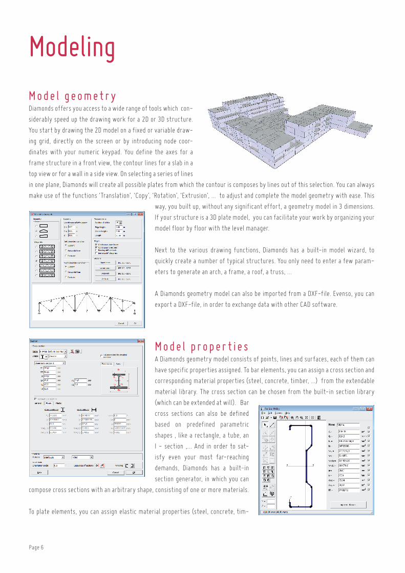
Mo de l ge om e t r yDiamonds offers you access to a wide range of tools which con-
siderably speed up the drawing work for a 2D or 3D structure.
you start by drawing the 2D model on a fixed or variable draw-
ing grid, directly on the screen or by introducing node coor-
dinates with your numeric keypad. you define the axes for a
frame structure in a front view, the contour lines for a slab in a
top view or for a wall in a side view. on selecting a series of lines
in one plane, Diamonds will create all possible plates from which the contour is composes by lines out of this selection. you can always
make use of the functions ‘translation’, ‘copy’, ‘rotation’, ‘extrusion’, ... to adjust and complete the model geometry with ease. this
way, you built up, without any significant effort, a geometry model in 3 dimensions.
if your structure is a 3D plate model, you can facilitate your work by organizing your
model floor by floor with the level manager.
next to the various drawing functions, Diamonds has a built-in model wizard, to
quickly create a number of typical structures. you only need to enter a few param-
eters to generate an arch, a frame, a roof, a truss, ...
a Diamonds geometry model can also be imported from a DXf-file. evenso, you can
export a DXf-file, in order to exchange data with other caD software.
Mo de l p r op er t ie sa Diamonds geometry model consists of points, lines and surfaces, each of them can
have specific properties assigned. to bar elements, you can assign a cross section and
corresponding material properties (steel, concrete, timber, ...) from the extendable
material library. the cross section can be chosen from the built-in section library
(which can be extended at will). bar
cross sections can also be defined
based on predefined parametric
shapes , like a rectangle, a tube, an
i - section ,... and in order to sat-
isfy even your most far-reaching
demands, Diamonds has a built-in
section generator, in which you can
compose cross sections with an arbitrary shape, consisting of one or more materials.
to plate elements, you can assign elastic material properties (steel, concrete, tim-

Page 7
ber, ... ) and a cross section. by default, Diamonds will consider all plates isotropic
and bearing in two (perpendicular) directions. besides that, it is possible to calcu-
late a other configurations. with Diamonds, you can calculate orthotropic plates, like
pre-slab floors, ribbed slabs, waffle slabs, voided slabs, and slabs bearing in a single
direction. these cross sections are
easily defined by means of a limited
number of physical parameters.
obviously, you can indicate how ele-
ments should behave with respect to
each other in the structure you are
calculating. the connection between
elements is considered as rigid by
default. however, it remains possible at any time to adapt such rigidity, between bar
and plates, as well as between plates or bars mutually. furthermore, you can add a
lower or upper haunch to bar ends, for which you can take into account the resistance
and stiffness in the global analysis.
Moreover, you can declare bars as tie rods and vertical plates as (brick) walls with
no tension transferat the top border possible. in that case, Diamonds will perform an
iterative calculation, for which tie rods/tension transfer (in case of brick wall) will
be eliminated if they would be active otherwise. this procedure is repeated until a
valid equilibrium is found.
S upp or t sonce the model geometry is set you can define supports for points, lines and plates.
Diamonds allows you to configure each of the six degrees of liberty, allowing you to
create any possible support. each point, line or plate support can be chosen as fix or
defined by a spring constant. furthermore, you can take into account the nonlinear
behaviour of supports not able to take any tension or compression forces. in this way,
you have a wide range of possibilities at your disposal.
Modeling

Page 8
Modeling
F oun d a t ion s l ab sDiamonds has extremely advanced iterative calculation possibilities, by which you can
describe accurately the local compressibility of soil layers under foundation slabs.
the soil under the slab is replaced by displacement springs in all mesh points and
the structures is calculated a first time with an arbitrary value for the springs. the
iterative calculation is based on laws of soil mechanics (boussinesq & terzaghi). these
laws can be used to calculate the stress changes due to the vertical reactions in the
springs on the settlements resulted from those changes. the calculated settlements
are being compared with the deformation of the foundation slab. Depending on the
difference between both, the spring elements describing the soil behaviour are ad-
justed, until the difference becomes negligible. it speaks for itself that soil mechani-
cal laws can only be applied if the relevant soil properties are known. these can be
directly derived from the soil testing report, composed of meterings by conducted with a penetrometer or Ménard pressiometer. the
above method does not only provide a great precision for the calculation of foundation slabs, it also allows you to take into account
the effect on subsoil of adjacent structures or excavations. in case of excavation, Diamonds will consider appropriately the reload-
ing constant a instead of the compressibility constant c. thus, you can calculate more realistic and possible risks can be curtailed.
F i r e h a z ar dwithin Diamonds’ user-friendly environment thermal and structural calculation are
perfectly integrated. you easily define a fire hazard based on the imposed fire curve
and the required fire resistance time. you can choose from several fire curves: stand-
ard fire iSo 834, external, hydrocarbon and parametric fire. next you specify the
required fire resistance duration. Standard i or h sections from the library or sections
based on a built-in shape can have three sides or all sides exposed to fire, or can be
coated with a thermal coating. Diamonds allows you to create for each bar several
variations of fire protection with the purpose of being able to quickly select the best
possible protection.
Page 9
Modeling
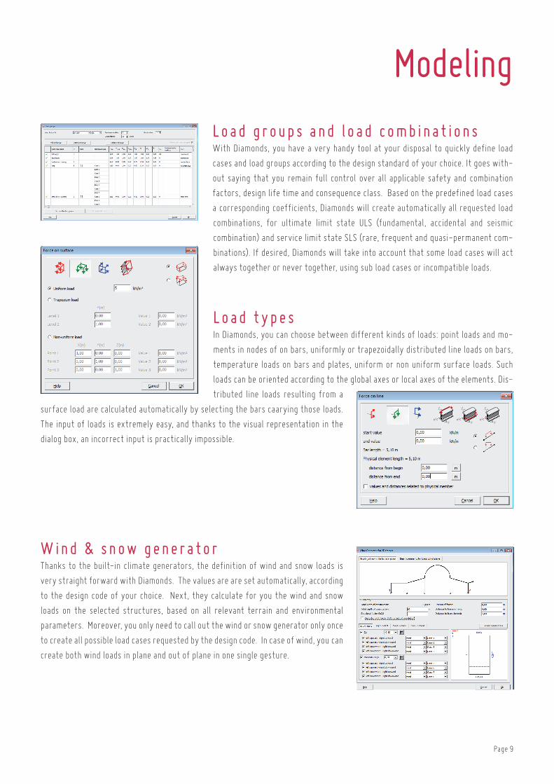
L o ad gr oup s and l o ad c ombin a t ion swith Diamonds, you have a very handy tool at your disposal to quickly define load
cases and load groups according to the design standard of your choice. it goes with-
out saying that you remain full control over all applicable safety and combination
factors, design life time and consequence class. based on the predefined load cases
a corresponding coefficients, Diamonds will create automatically all requested load
combinations, for ultimate limit state ulS (fundamental, accidental and seismic
combination) and service limit state SlS (rare, frequent and quasi-permanent com-
binations). if desired, Diamonds will take into account that some load cases will act
always together or never together, using sub load cases or incompatible loads.
L o ad t y p e sin Diamonds, you can choose between different kinds of loads: point loads and mo-
ments in nodes of on bars, uniformly or trapezoidally distributed line loads on bars,
temperature loads on bars and plates, uniform or non uniform surface loads. Such
loads can be oriented according to the global axes or local axes of the elements. Dis-
tributed line loads resulting from a
surface load are calculated automatically by selecting the bars caarying those loads.
the input of loads is extremely easy, and thanks to the visual representation in the
dialog box, an incorrect input is practically impossible.
W ind & s n o w gen er a t orthanks to the built-in climate generators, the definition of wind and snow loads is
very straight forward with Diamonds. the values are are set automatically, according
to the design code of your choice. next, they calculate for you the wind and snow
loads on the selected structures, based on all relevant terrain and environmental
parameters. Moreover, you only need to call out the wind or snow generator only once
to create all possible load cases requested by the design code. in case of wind, you can
create both wind loads in plane and out of plane in one single gesture.

Page 10
D y n amic l o ad sDiamonds allows you to consider an unlimited number of loads as dynamic loads. you
can take into account various types of dynamic loads: harmonic (like loads caused by
a machine working at a stationary number of rotations), periodic (like loads caused
by people moving around in a building) or even transient loads (of which the variation
in time does not have any periodic repetition). Dynamic actions can be considered as a
variation of the defined loads or as an acceleration of the supports.
S e i s mic l o ad sfor structures in seismic sensitive regions, you can impose at the base of the model
a ground acceleration. the corresponding action on the structure is described by a
seismic design spectrum. Diamonds can not only take the horizontal seismic action
into account, by means of the seimic design spectra in two perpendicular actions, but
it can also generate the vertical component of the seismic action.
Mo v ing l o ad sa load train is by definition a set of charges that move together according to a speci-
fied path. the flexible definable load trains are available for each load group and are
modeled along straight or curved paths. a load train may consist of one single or
multiple point and/or line loads. load trains can be synchronized with each other by
means of stops in between. in addition, all ever defined Diamonds last trains collected
in a ‘load train’ library, available for each Diamonds project. Multiple load trains can
be combined within a load group, so that the deformation and resistance of double girder crane tracks under the action of moving
loads are easily assessable. when there are one or more load trains are defined, simultaneous movement can be visualized, thanks to
an animated representation of the rolling load trains.
Modeling

Page 11
Page 12
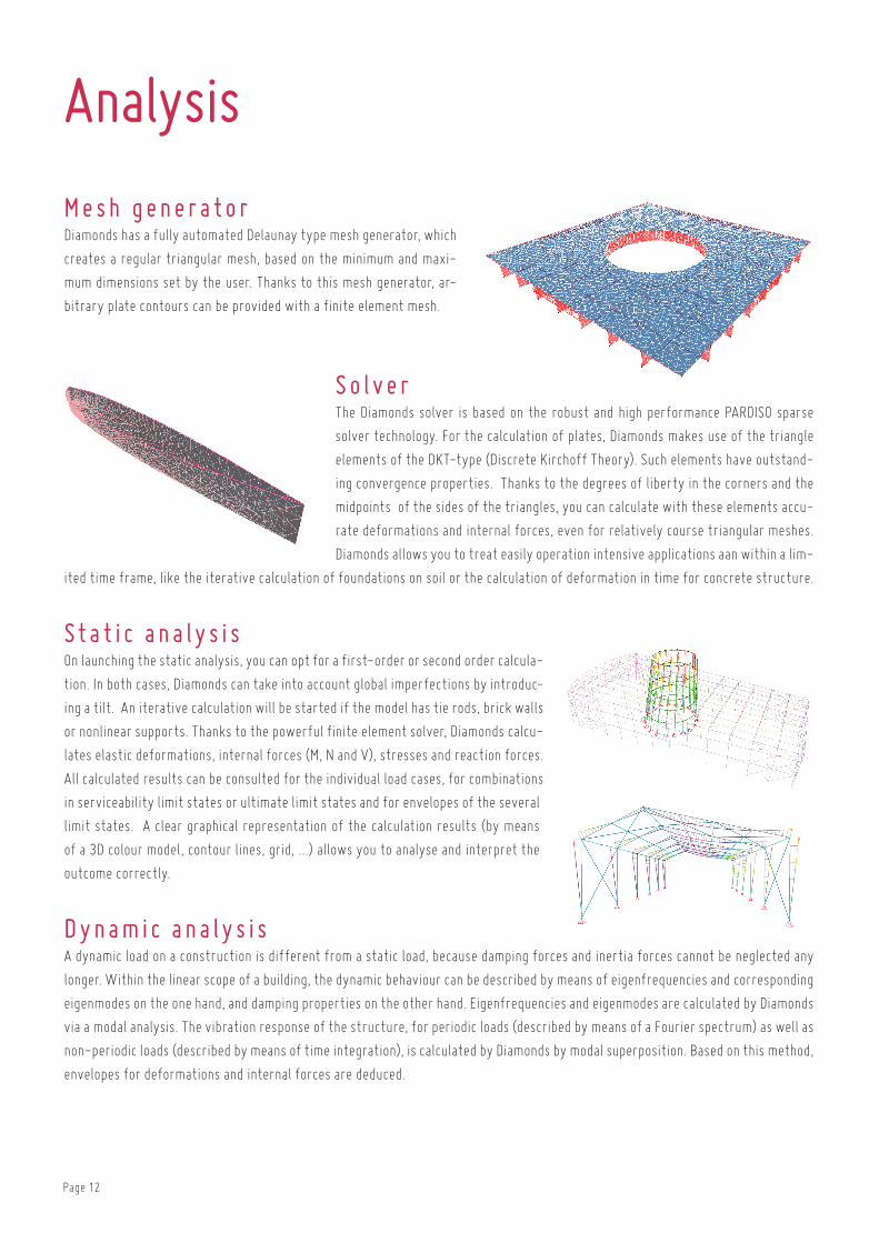
Me s h gen er a t orDiamonds has a fully automated Delaunay type mesh generator, which
creates a regular triangular mesh, based on the minimum and maxi-
mum dimensions set by the user. thanks to this mesh generator, ar-
bitrary plate contours can be provided with a finite element mesh.
S o l v erthe Diamonds solver is based on the robust and high performance ParDiSo sparse
solver technology. for the calculation of plates, Diamonds makes use of the triangle
elements of the DKt-type (Discrete Kirchoff theory). Such elements have outstand-
ing convergence properties. thanks to the degrees of liberty in the corners and the
midpoints of the sides of the triangles, you can calculate with these elements accu-
rate deformations and internal forces, even for relatively course triangular meshes.
Diamonds allows you to treat easily operation intensive applications aan within a lim-
ited time frame, like the iterative calculation of foundations on soil or the calculation of deformation in time for concrete structure.
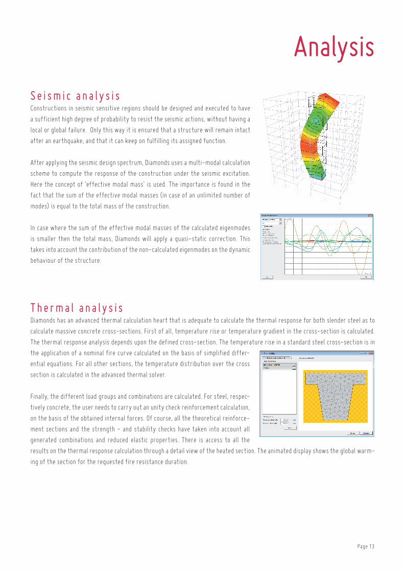
St a t i c an a l y s i son launching the static analysis, you can opt for a first-order or second order calcula-
tion. in both cases, Diamonds can take into account global imperfections by introduc-
ing a tilt. an iterative calculation will be started if the model has tie rods, brick walls
or nonlinear supports. thanks to the powerful finite element solver, Diamonds calcu-
lates elastic deformations, internal forces (M, n and V), stresses and reaction forces.
all calculated results can be consulted for the individual load cases, for combinations
in serviceability limit states or ultimate limit states and for envelopes of the several
limit states. a clear graphical representation of the calculation results (by means
of a 3D colour model, contour lines, grid, ...) allows you to analyse and interpret the
outcome correctly.
D y n amic an a l y s i sa dynamic load on a construction is different from a static load, because damping forces and inertia forces cannot be neglected any
longer. within the linear scope of a building, the dynamic behaviour can be described by means of eigenfrequencies and corresponding
eigenmodes on the one hand, and damping properties on the other hand. eigenfrequencies and eigenmodes are calculated by Diamonds
via a modal analysis. the vibration response of the structure, for periodic loads (described by means of a fourier spectrum) as well as
non-periodic loads (described by means of time integration), is calculated by Diamonds by modal superposition. based on this method,
envelopes for deformations and internal forces are deduced.
Analysis
Page 13
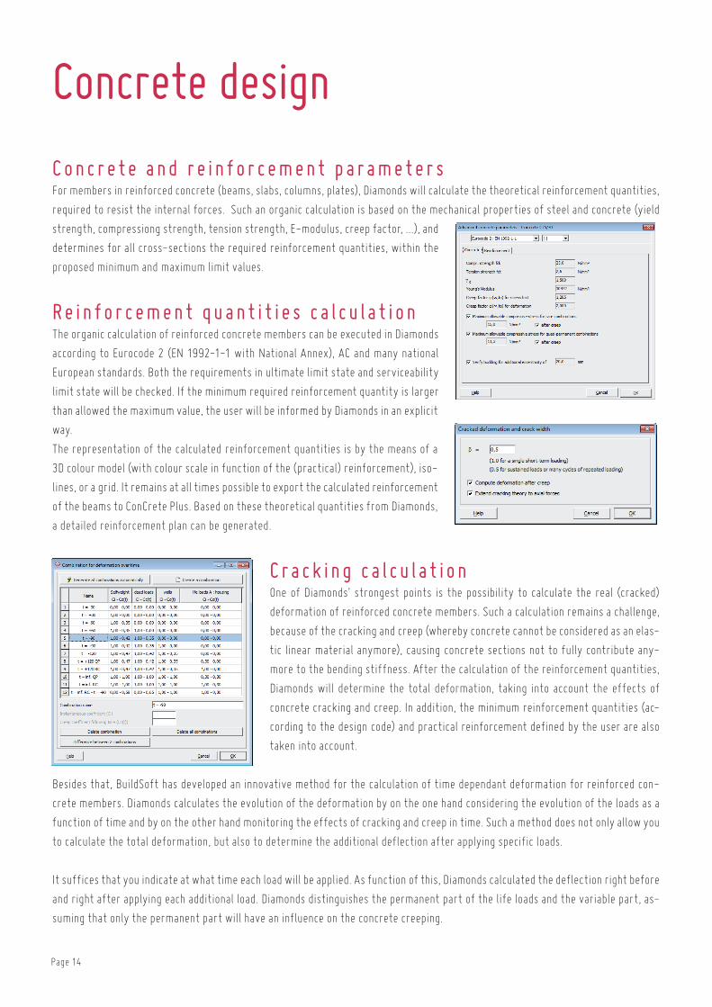
S e i s mic an a l y s i sconstructions in seismic sensitive regions should be designed and executed to have
a sufficient high degree of probability to resist the seismic actions, without having a
local or global failure. only this way it is ensured that a structure will remain intact
after an earthquake, and that it can keep on fulfilling its assigned function.
after applying the seismic design spectrum, Diamonds uses a multi-modal calculation
scheme to compute the response of the construction under the seismic excitation.
here the concept of ‘effective modal mass’ is used. the importance is found in the
fact that the sum of the effective modal masses (in case of an unlimited number of
modes) is equal to the total mass of the construction.
in case where the sum of the effective modal masses of the calculated eigenmodes
is smaller then the total mass, Diamonds will apply a quasi-static correction. this
takes into account the contribution of the non-calculated eigenmodes on the dynamic
behaviour of the structure.
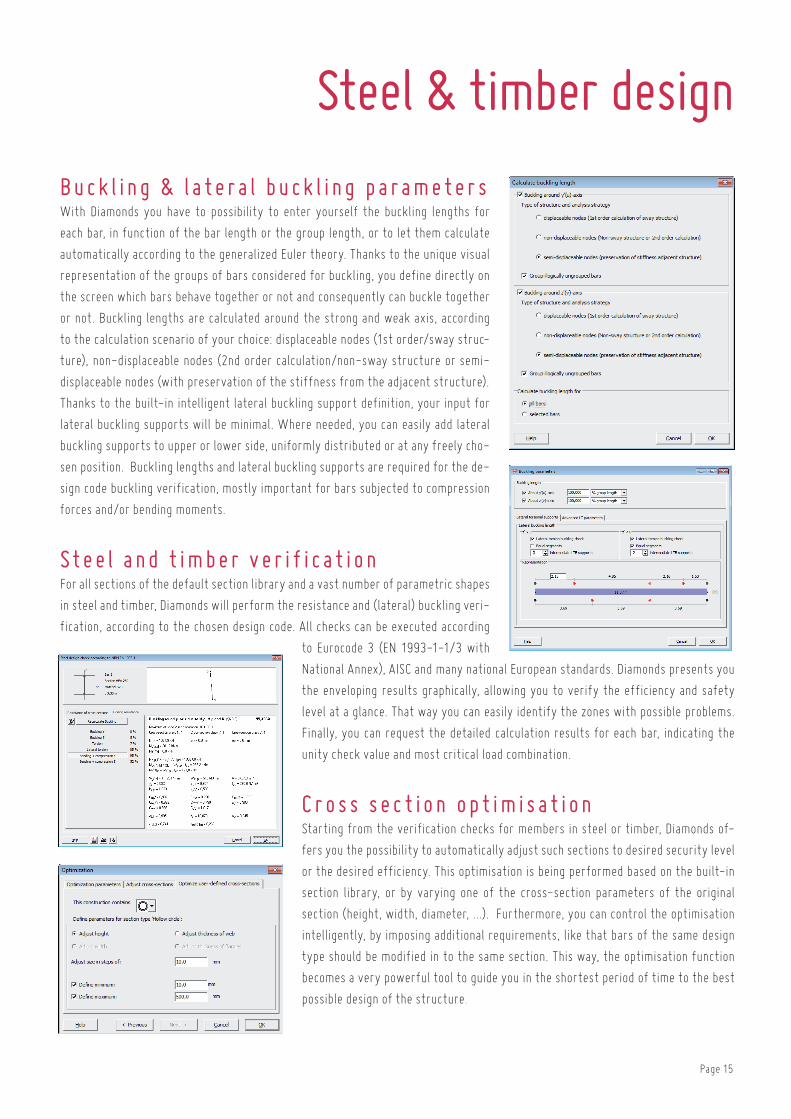
T her m a l an a l y s i sDiamonds has an advanced thermal calculation heart that is adequate to calculate the thermal response for both slender steel as to
calculate massive concrete cross-sections. first of all, temperature rise or temperature gradient in the cross-section is calculated.
the thermal response analysis depends upon the defined cross-section. the temperature rise in a standard steel cross-section is in
the application of a nominal fire curve calculated on the basis of simplified differ-
ential equations. for all other sections, the temperature distribution over the cross
section is calculated in the advanced thermal solver.
finally, the different load groups and combinations are calculated. for steel, respec-
tively concrete, the user needs to carry out an unity check reinforcement calculation,
on the basis of the obtained internal forces. of course, all the theoretical reinforce-
ment sections and the strength - and stability checks have taken into account all
generated combinations and reduced elastic properties. there is access to all the
results on the thermal response calculation through a detail view of the heated section. the animated display shows the global warm-
ing of the section for the requested fire resistance duration.
Analysis
Page 14
Concrete design
C on c r e t e and r e in f or c em en t p ar am e t er s for members in reinforced concrete (beams, slabs, columns, plates), Diamonds will calculate the theoretical reinforcement quantities,
required to resist the internal forces. Such an organic calculation is based on the mechanical properties of steel and concrete (yield
strength, compressiong strength, tension strength, e-modulus, creep factor, ...), and
determines for all cross-sections the required reinforcement quantities, within the
proposed minimum and maximum limit values.
R e in f or c em en t qu an t i t ie s c a l c u l a t ionthe organic calculation of reinforced concrete members can be executed in Diamonds
according to eurocode 2 (en 1992-1-1 with national annex), ac and many national
european standards. both the requirements in ultimate limit state and serviceability
limit state will be checked. if the minimum required reinforcement quantity is larger
than allowed the maximum value, the user will be informed by Diamonds in an explicit
way.
the representation of the calculated reinforcement quantities is by the means of a
3D colour model (with colour scale in function of the (practical) reinforcement), iso-
lines, or a grid. it remains at all times possible to export the calculated reinforcement
of the beams to concrete Plus. based on these theoretical quantities from Diamonds,
a detailed reinforcement plan can be generated.
C r ac k ing c a l c u l a t ionone of Diamonds’ strongest points is the possibility to calculate the real (cracked)
deformation of reinforced concrete members. Such a calculation remains a challenge,
because of the cracking and creep (whereby concrete cannot be considered as an elas-
tic linear material anymore), causing concrete sections not to fully contribute any-
more to the bending stiffness. after the calculation of the reinforcement quantities,
Diamonds will determine the total deformation, taking into account the effects of
concrete cracking and creep. in addition, the minimum reinforcement quantities (ac-
cording to the design code) and practical reinforcement defined by the user are also
taken into account.
besides that, buildSoft has developed an innovative method for the calculation of time dependant deformation for reinforced con-
crete members. Diamonds calculates the evolution of the deformation by on the one hand considering the evolution of the loads as a
function of time and by on the other hand monitoring the effects of cracking and creep in time. Such a method does not only allow you
to calculate the total deformation, but also to determine the additional deflection after applying specific loads.
it suffices that you indicate at what time each load will be applied. as function of this, Diamonds calculated the deflection right before
and right after applying each additional load. Diamonds distinguishes the permanent part of the life loads and the variable part, as-
suming that only the permanent part will have an influence on the concrete creeping.
Page 15
Steel & timber design
Buc k l ing & l a t e r a l buc k l ing p ar am e t er swith Diamonds you have to possibility to enter yourself the buckling lengths for
each bar, in function of the bar length or the group length, or to let them calculate
automatically according to the generalized euler theory. thanks to the unique visual
representation of the groups of bars considered for buckling, you define directly on
the screen which bars behave together or not and consequently can buckle together
or not. buckling lengths are calculated around the strong and weak axis, according
to the calculation scenario of your choice: displaceable nodes (1st order/sway struc-
ture), non-displaceable nodes (2nd order calculation/non-sway structure or semi-
displaceable nodes (with preservation of the stiffness from the adjacent structure).
thanks to the built-in intelligent lateral buckling support definition, your input for
lateral buckling supports will be minimal. where needed, you can easily add lateral
buckling supports to upper or lower side, uniformly distributed or at any freely cho-
sen position. buckling lengths and lateral buckling supports are required for the de-
sign code buckling verification, mostly important for bars subjected to compression
forces and/or bending moments.
St e e l an d t imb er v er i f i c a t ion for all sections of the default section library and a vast number of parametric shapes
in steel and timber, Diamonds will perform the resistance and (lateral) buckling veri-
fication, according to the chosen design code. all checks can be executed according
to eurocode 3 (en 1993-1-1/3 with
national annex), aiSc and many national european standards. Diamonds presents you
the enveloping results graphically, allowing you to verify the efficiency and safety
level at a glance. that way you can easily identify the zones with possible problems.
finally, you can request the detailed calculation results for each bar, indicating the
unity check value and most critical load combination.
C r o s s s e c t ion op t imis a t ion Starting from the verification checks for members in steel or timber, Diamonds of-
fers you the possibility to automatically adjust such sections to desired security level
or the desired efficiency. this optimisation is being performed based on the built-in
section library, or by varying one of the cross-section parameters of the original
section (height, width, diameter, ...). furthermore, you can control the optimisation
intelligently, by imposing additional requirements, like that bars of the same design
type should be modified in to the same section. this way, the optimisation function
becomes a very powerful tool to guide you in the shortest period of time to the best
possible design of the structure.
Page 16
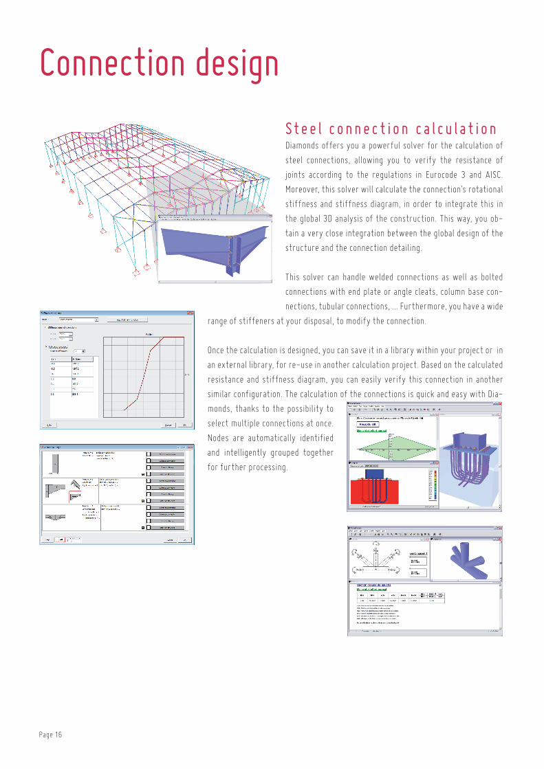
St e e l c onn e c t ion c a l c u l a t ionDiamonds offers you a powerful solver for the calculation of
steel connections, allowing you to verify the resistance of
joints according to the regulations in eurocode 3 and aiSc.
Moreover, this solver will calculate the connection’s rotational
stiffness and stiffness diagram, in order to integrate this in
the global 3D analysis of the construction. this way, you ob-
tain a very close integration between the global design of the
structure and the connection detailing.
this solver can handle welded connections as well as bolted
connections with end plate or angle cleats, column base con-
nections, tubular connections, ... furthermore, you have a wide
range of stiffeners at your disposal, to modify the connection.
once the calculation is designed, you can save it in a library within your project or in
an external library, for re-use in another calculation project. based on the calculated
resistance and stiffness diagram, you can easily verify this connection in another
similar configuration. the calculation of the connections is quick and easy with Dia-
monds, thanks to the possibility to
select multiple connections at once.
nodes are automatically identified
and intelligently grouped together
for further processing.
Connection design

Page 17
Report
you can document your work in a clear and organized report. the unique sub-report
method allows you to create a fully custom report. in the report manager dialogue
you get an overview of all created sub-reports. for each sub-report, you define the
contents (geometry, loads, global & detail results), point of view and the elements to
be included. the way of working allows you to focus on specific important elements
in the structure. a handy dialogue window guides you through the numerous options
and possibilities to insert data and results, represented both in a graphical way as
well as in a table.
Diamonds generates for you automatically a table of contents, based on the report’s
titles. this table of contents can be made for each sub-report separately or for the
selected sub reports together. at page’s header and footer you can easily add your
company name, company logo, creation date, name of the project, ... or any arbitrary
text. the final report can be sent to the printer directly (with preview possibility), or
can be saved as an rtf file (rich text format), which can be opened in your favourite
text editor. this way you can modify the document at all times and deliver a complete
personalized report. each sub-report is saved with the calculation project. further-
more, you can save the configuration settings of each report and import them in a
next calculation project.
Page 18
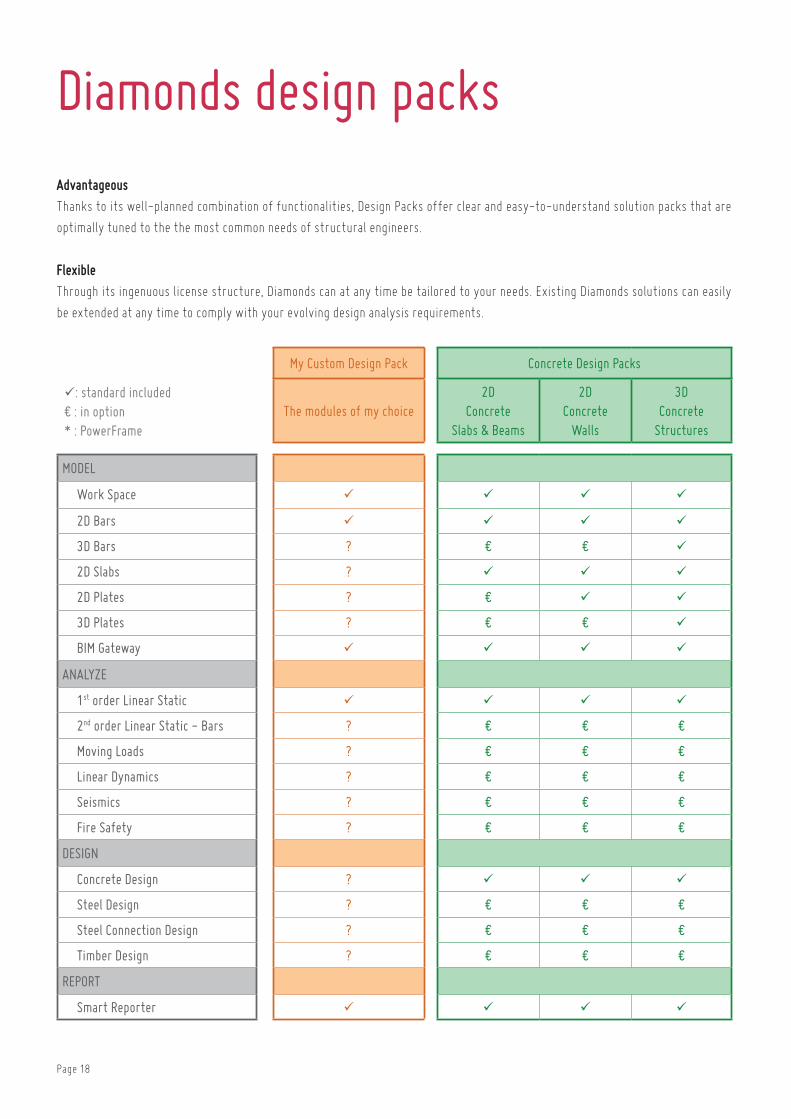
My Custom Design Pack Concrete Design Packs Steel Design Packs Structural Design Packs
: standard included € : in option* : PowerFrame
The modules of my choice2D
Concrete Slabs & Beams
2DConcrete
Walls
3D Concrete
Structures
2D Steel
Frames
3D Steel
Frames
3D Steel
Frames Plus
2D Frames
2D Frames
and Slabs
3D Frames on Slabs
3D Structures
3D Structures
Plus
MoDEL
Work Space
2D Bars
3D Bars ? € € € € €
2D Slabs ? € € € €
2D Plates ? € € € € € € €
3D Plates ? € € € € € € € €
BIM Gateway
ANALYzE
1st order Linear Static
2nd order Linear Static - Bars ? € € €
Moving Loads ? € € € € € € € € € € €
Linear Dynamics ? € € € € € € € € € € €
Seismics ? € € € € € € € € € € €
Fire Safety ? € € € € € € € € € € €
DESIGN
Concrete Design ? € € €
Steel Design ? € € €
Steel Connection Design ? € € € € € € € € €
Timber Design ? € € € € € €
REPoRT
Smart Reporter
Diamonds design packsAdvantageousthanks to its well-planned combination of functionalities, Design Packs offer clear and easy-to-understand solution packs that are
optimally tuned to the the most common needs of structural engineers.
Flexiblethrough its ingenuous license structure, Diamonds can at any time be tailored to your needs. existing Diamonds solutions can easily
be extended at any time to comply with your evolving design analysis requirements.
Page 19
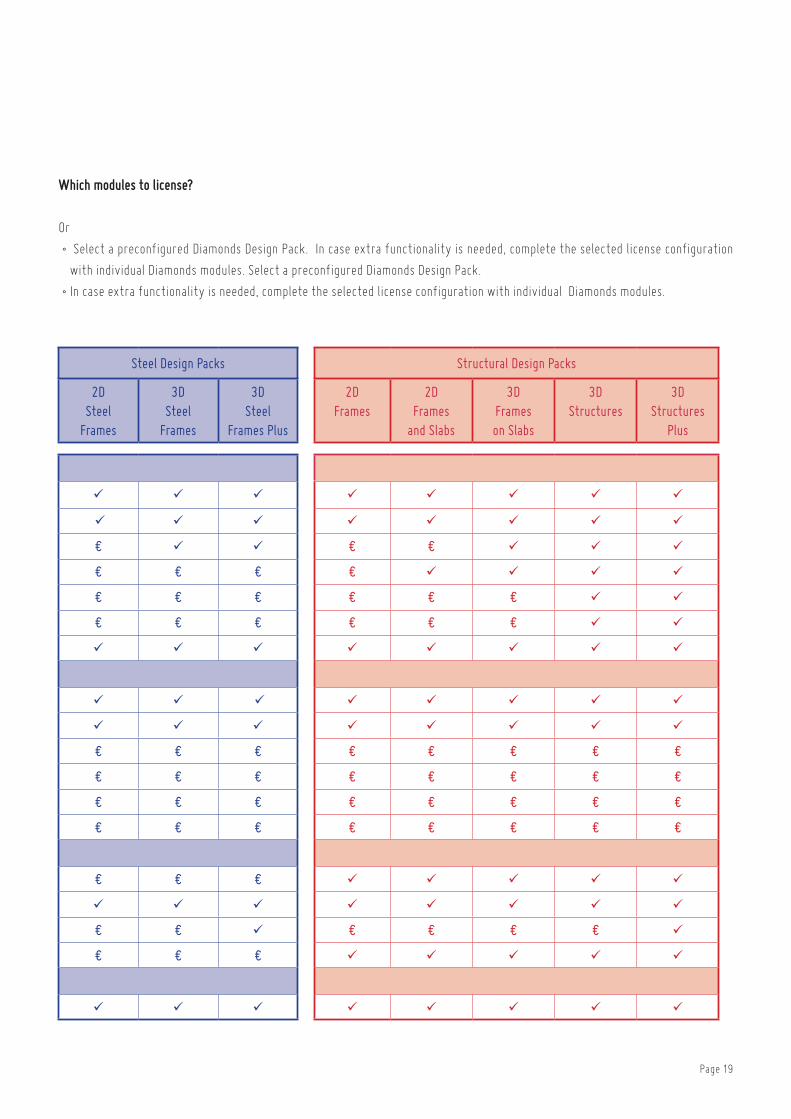
My Custom Design Pack Concrete Design Packs Steel Design Packs Structural Design Packs
: standard included € : in option* : PowerFrame
The modules of my choice2D
Concrete Slabs & Beams
2DConcrete
Walls
3D Concrete
Structures
2D Steel
Frames
3D Steel
Frames
3D Steel
Frames Plus
2D Frames
2D Frames
and Slabs
3D Frames on Slabs
3D Structures
3D Structures
Plus
MoDEL
Work Space
2D Bars
3D Bars ? € € € € €
2D Slabs ? € € € €
2D Plates ? € € € € € € €
3D Plates ? € € € € € € € €
BIM Gateway
ANALYzE
1st order Linear Static
2nd order Linear Static - Bars ? € € €
Moving Loads ? € € € € € € € € € € €
Linear Dynamics ? € € € € € € € € € € €
Seismics ? € € € € € € € € € € €
Fire Safety ? € € € € € € € € € € €
DESIGN
Concrete Design ? € € €
Steel Design ? € € €
Steel Connection Design ? € € € € € € € € €
Timber Design ? € € € € € €
REPoRT
Smart Reporter
Which modules to license?
or
• Select a preconfigured Diamonds Design Pack. in case extra functionality is needed, complete the selected license configuration
with individual Diamonds modules. Select a preconfigured Diamonds Design Pack.
•in case extra functionality is needed, complete the selected license configuration with individual Diamonds modules.

Page 20
Model - AnAlyze - Design - RepoRt
“the energy arc”, construction with solar panels in front of the Photovoltech offices, tienen (b) - engineering office: liSSt, loonbeek (b) -
architect: aSt 77 (b)
Fast & accurate
both the regular and the occasional user will be able to
translate structural design concepts into powerful analysis
models, allowing for inventive yet economical designs that
comply with current design standards.
User-friendly
allowing for a fully transparent management of your struc-
tural design analysis models, Diamonds accommodates it-
self to your needs and preferences. its highly intuitive and
versatile working environment enables you to do your job
with minimal effort.
Work Space

Page 21
F e at ur e sModel definitiongraphical definition on regular or variable grid.
Definition based on absolute or relative point coordinates.
Various supporting drawing functions: translate, copy, ro-
tate, mirror, extrude, projections ...
control measurement function.
import of DXf, Powerframe, PowerPlate and Diamonds files.
export to DXf, DStV, bMP and biM expert files.
Model managementlevel-based management of building models (definition,
visibility, ...).
logical grouping of physical elements into design types.
Model visualisationwide range of visualisation options:
• wireframe rendering
• transparent or non-transparent surface rendering
• volume rendering ( black-and-white or colour )
hide/show parts of the model for improved readability.
Model visualisation based on four standard window configu-
rations (geometry, loads, Mesh, results) or configurations
definable by the user.
Quick adjustment of size of fonts, symbols, loads and re-
sults.
Model interactionSelection of elements based on different criteria (number,
section, material, design type, … ).
convenient zoom/orbit/pan functions.
Working environmentchoice between english, french, Dutch, german, Spanish
and Polish language.
built-in unit management system.
automatic save and backup options for Diamonds files.
easy access to built-in context-sensitive help function
from each dialog box.
Page 22
Model - AnAlyze - Design - RepoRt
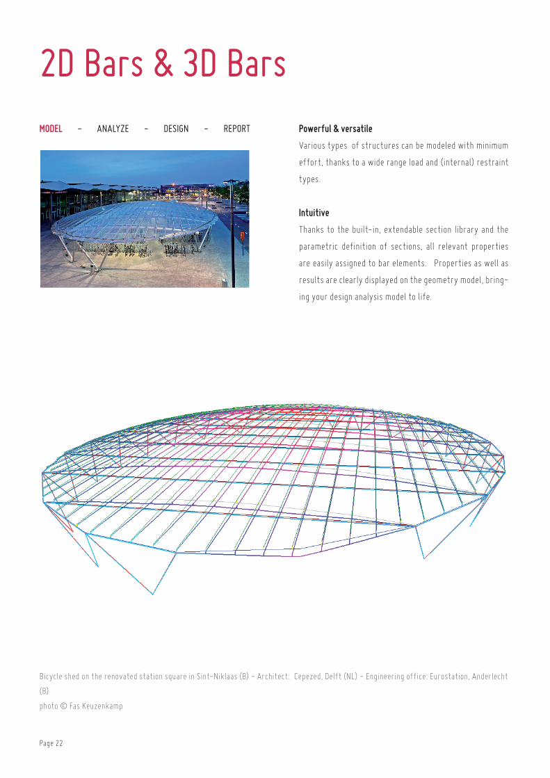
bicycle shed on the renovated station square in Sint-niklaas (b) - architect: cepezed, Delft (nl) - engineering office: eurostation, anderlecht
(b)
photo © fas Keuzenkamp
Powerful & versatile
Various types of structures can be modeled with minimum
effort, thanks to a wide range load and (internal) restraint
types.
Intuitive
thanks to the built-in, extendable section library and the
parametric definition of sections, all relevant properties
are easily assigned to bar elements. Properties as well as
results are clearly displayed on the geometry model, bring-
ing your design analysis model to life.
2D Bars & 3D Bars

Page 23
F e at ur e sgraphical definition of model geometry using points and
lines. import of geometry model from DXf-file. wizard for
basic structures.
Definition of beams and columns coming from on extendable
section library, based on parametric section types or a sec-
tion completely definable by user.
Modeling of beams, columns, 2D or 3D frames, beam grids
(possibilities depend on license), ...
rigid link elements for modelling eccentric connections be-
tween bar elements.
transparent management of construction materials from
within extendable material library.
release at bar ends using generalized hinge elements:
• release with respect to axial force, shear force and/or
moments
• full or partial release (elastic connection elements
based on stifness value or stifness diagram)
Definition of tie rods.
elastic or rigid restraints, allowing for elimination of tensile
or compression reaction forces.
elastic support of bar elements according to winkler theory
or using inhomogeneous elastic support based on soil layer
profiles (iterative equilibrium approach based on boussin-
esq & terzaghi laws)
graphical definition of loads and restraints on model geom-
etry, according to global or local coordinate system.
easy load management with load groups and subgroups.
wide choice of mechanical loads (point loads, line loads &
surface loads) and thermal loads (temperature raise/fall &
temperature gradient).
automatic generation of wind and snow loads according to
eurocode en 1991 (with relevant national annex),.
automatic generation of design load combinations based on
load combination and safety factors according to eurocode
en 1990 (with relevant national annex), aSce 7-10 lrfD,
nSr-10, nen 6702, nen 8700, cte and Si 412.
geometry and load element informations available and ed-
itable in tables.
fast copy-paste function for sections, supports and loads.
Page 24
Model - AnAlyze - Design - RepoRt
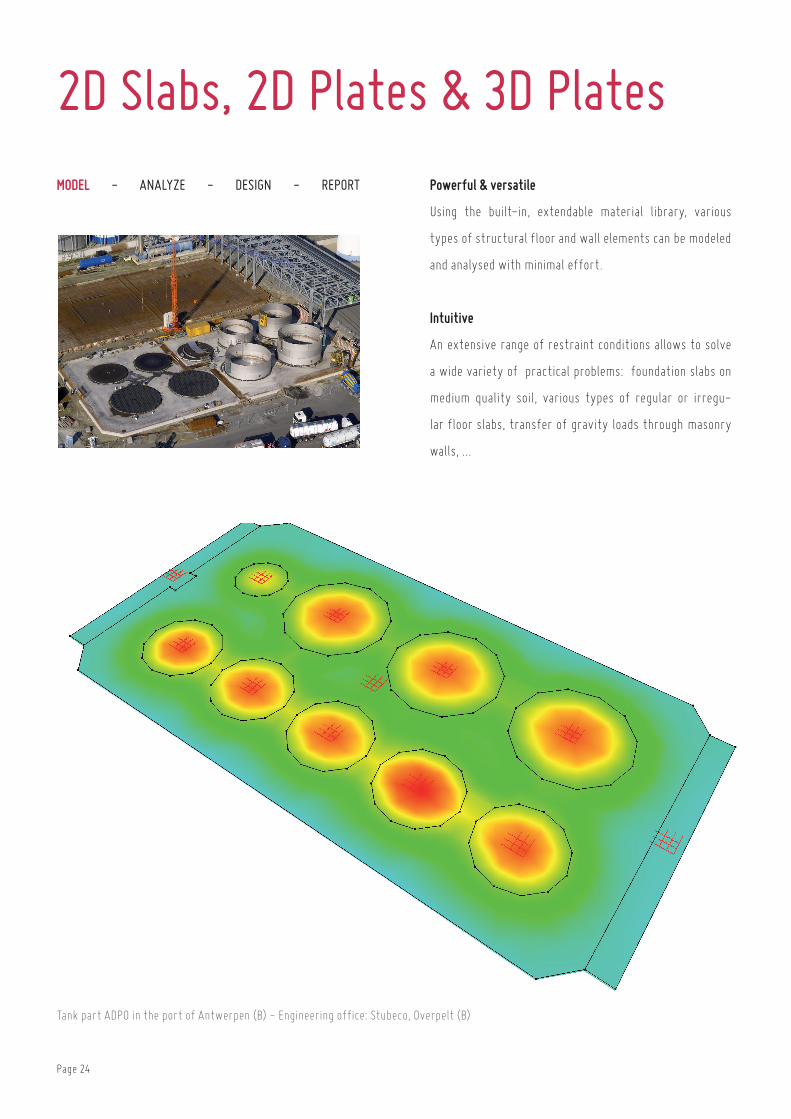
tank part aDPo in the port of antwerpen (b) - engineering office: Stubeco, overpelt (b)
Powerful & versatile
using the built-in, extendable material library, various
types of structural floor and wall elements can be modeled
and analysed with minimal effort.
Intuitive
an extensive range of restraint conditions allows to solve
a wide variety of practical problems: foundation slabs on
medium quality soil, various types of regular or irregu-
lar floor slabs, transfer of gravity loads through masonry
walls, …
2D Slabs, 2D Plates & 3D Plates

Page 25
F e at ur e sgrafical definition of model geometry using point, lines &
surfaces. import of geometry model from DXf-file.
Modelling of floor-slabs, pre-slabs, mushroom slabs, ortho-
tropic floor slabs, hollow-core slabs, ground beams, rafts,...
3D analysis of structurs built up of floors, walls and founda-
tion elements. (depending on license)
transparent management of construction materials from
within extendable material library.
rigid link elements for modelling eccentric connections be-
tween bars and plates.
release at plate edges using generalized hinge elements:
• release with respect to axial force, shear force and/or
moments
• full or partial release (elastic connection elements)
Definition of masonry wall elements.
graphical definition of loads and restraints on model geom-
etry, according to global or local coordinate system.
elastic or rigid restraints, allowing for elimination of tensile
or compression reaction forces.
elastic support of bar elements according to winkler theory
or using inhomogeneous elastic support based on soil layer
profiles (iterative equilibrium approach based on boussin-
esq & terzaghi laws)
easy load management with load groups and subgroups.
wide choice of mechanical loads (point loads, line loads &
surface loads) and thermal loads (temperature raise/fall &
temperature gradient).
automatic generation of design load combinations based on
load combination and safety factors according to eurocode
en 1990 (with relevant national annex), aSce 7-10 lrfD,
nSr-10, nen 6702, nen 8700, cte and Si 412.
geometry and load element informations availabel and ed-
itable in tables.
fast copy-paste function for sections, supports and loads

Page 26
Model - AnAlyze - design - RepoRt
concrete canoe for concrete canoe race in 2011 - calculated by student sorority betonbrouwers of utwente
photo © Victoria Kühne
Efficient
the 3D analysis engine based on ParDiSo sparse solver
technology makes optimal use of the raM-memory avail-
able on your workstation, solving even highly complex mod-
els in a short time frame.
Transparent
Diamonds offers a direct, no-nonsense access to its multi-
tude of design analysis results. Make the analysis results
speak for themselves and increase your insight into the
structural behaviour of your building models.
1st & 2nd order Analysis

Page 27
F e at ur e s1st Order analysisrapid, automated conversion of geometry model into design
analysis model by means of Delaunay mesh generator.
Powerful 3D finite element analysis engine based on ParD-
iSo sparse solver technology, with support of bar-, beam-,
slab- and plate elements.
first order elastic analysis for statics with equilibrium
check and possibility to take imperfections into account .
calculation of deformations, deflections, angular rotations,
internal forces, elastic stresses and reaction forces.
Visualisation of analysis results:
• for individual load cases,
• for serviceability or ultimate limit state combinations,
• for various limit state envelopes.
Visualisation of analysis results on entire model geometry
or on selection of model objects.
Visualisation using colour map or isocontours.
Visualisation of analysis results on slabs and walls along
section cuts. evaluation of total and average values along
section cuts.
complementary results window for detailed representation
of analysis results:
• on selection of plate elements within a single plane,
• on selection of beam elements along a single line,
• on selection of section cuts along a single line.
complementary detailed results window with graphical rep-
resentation of stresses in bar’s cross-section.
Quick access to exact results at a specific bar or plate posi-
tion.
2nd Order analysisSecond-order static analysis with user-controlled accuracy
level.
calculation of global buckling factor for each load group and
1ste mode of global buckling.
Page 28
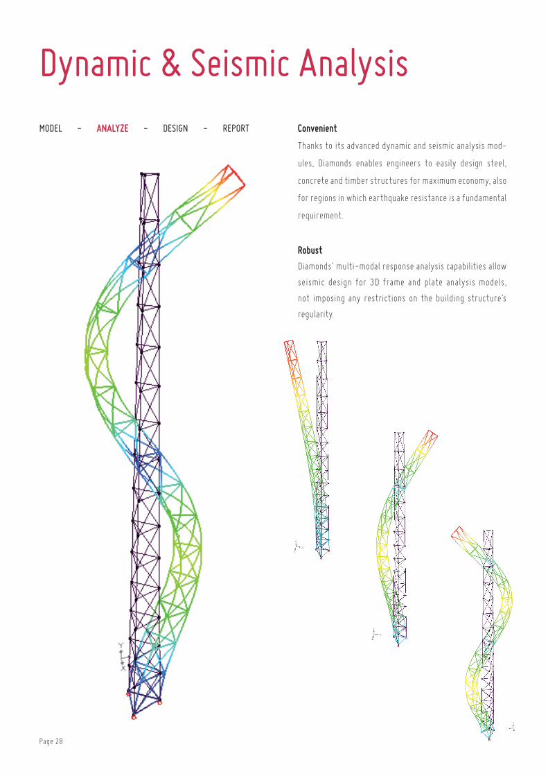
Model - AnAlyze - design - RepoRt Convenient
thanks to its advanced dynamic and seismic analysis mod-
ules, Diamonds enables engineers to easily design steel,
concrete and timber structures for maximum economy, also
for regions in which earthquake resistance is a fundamental
requirement.
Robust
Diamonds’ multi-modal response analysis capabilities allow
seismic design for 3D frame and plate analysis models,
not imposing any restrictions on the building structure’s
regularity.
Dynamic & Seismic Analysis
Page 29
F e at ur e sautomated definition of design gravity loads to be consid-
ered during modal analysis. Design gravity loads are derived
as a function of the permanent loads and a fraction of the
life loads through correlation coefficients.
calculation of a user defined number of eigenfrequencies
and eigenmodes, within a custom frequency interval. choice
between rayleigh damping and measered damping ratios.
Visualisation of structure’s deformations, angular rota-
tions, internal forces, elastic stresses and reaction forces
for calculated eigenmodes.
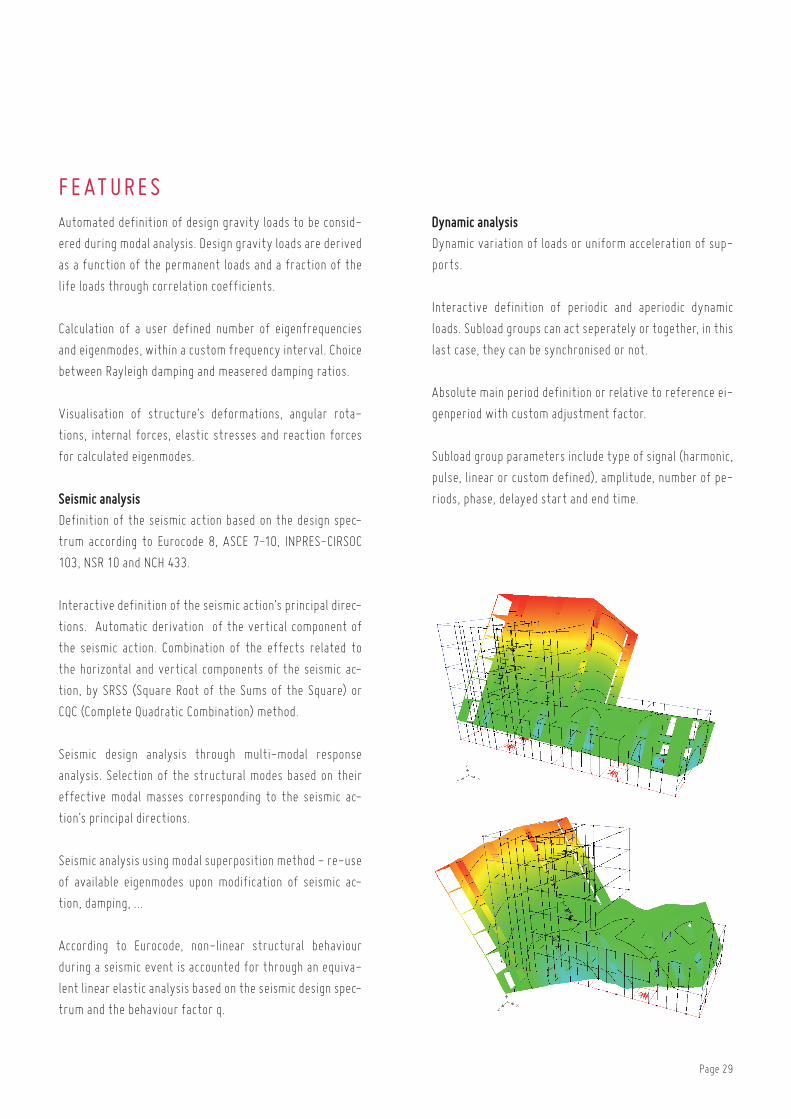
Seismic analysisDefinition of the seismic action based on the design spec-
trum according to eurocode 8, aSce 7-10, inPreS-cirSoc
103, nSr 10 and nch 433.
interactive definition of the seismic action’s principal direc-
tions. automatic derivation of the vertical component of
the seismic action. combination of the effects related to
the horizontal and vertical components of the seismic ac-
tion, by SrSS (Square root of the Sums of the Square) or
cQc (complete Quadratic combination) method.
Seismic design analysis through multi-modal response
analysis. Selection of the structural modes based on their
effective modal masses corresponding to the seismic ac-
tion’s principal directions.
Seismic analysis using modal superposition method - re-use
of available eigenmodes upon modification of seismic ac-
tion, damping, …
according to eurocode, non-linear structural behaviour
during a seismic event is accounted for through an equiva-
lent linear elastic analysis based on the seismic design spec-
trum and the behaviour factor q.
Dynamic analysisDynamic variation of loads or uniform acceleration of sup-
ports.
interactive definition of periodic and aperiodic dynamic
loads. Subload groups can act seperately or together, in this
last case, they can be synchronised or not.
absolute main period definition or relative to reference ei-
genperiod with custom adjustment factor.
Subload group parameters include type of signal (harmonic,
pulse, linear or custom defined), amplitude, number of pe-
riods, phase, delayed start and end time.

Page 30
Model - AnAlyze - design - RepoRt Comfortablz
in order to define moving loads in a comfortable way, you
can make use of a ‘load train’. Diamonds calculates the
structure through for each position of the load train and
compile the results in the form of an envelope.
Visual
thanks to the animated display of the rolling load trains you
have full control at any time. if you have defined differ-
ent load trains in a single load group, you can visualize the
simultaneous movement of the trains. thus, one can easily
verify that all load trains were defined correctly.
Moving Loads Analysis
Page 31
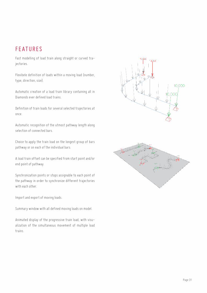
F e at ur e sfast modelling of load train along straight or curved tra-
jectories.
flexibele definition of loads within a moving load (number,
type, direction, size).
automatic creation of a load train library containing all in
Diamonds ever defined load trains.
Definition of train loads for several selected trajectories at
once.
automatic recognition of the utmost pathway length along
selection of connected bars.
choice to apply the train load on the longest group of bars
pathway or on each of the individual bars.
a load train offset can be specified from start point and/or
end point of pathway.
Synchronization points or stops assignable to each point of
the pathway in order to synchronize different trajectories
with each other.
import and export of moving loads.
Summary window with all defined moving loads on model.
animated display of the progressive train load, with visu-
alization of the simultaneous movement of multiple load
trains.

Page 32
Model - AnAlyze - design - RepoRt Flexible
Diamonds’ extensive material library and flexible section
utility tool allow for a quick and efficient definition of a
wide range of composite cross-sections, both in terms of
mechanical and thermal properties.
Powerfull
as Diamonds includes an advanced thermodynamic solver,
both solid and slender type of cross-sections can be ana-
lysed accurately with respect to fire resistance require-
ments.
Fire Resistance Analysis

Page 33
F e at ur e sextensive material library, fully customizable by the user.
Several material types can be defined using an appropriate
set of material properties: idealized fire buffers, fire pro-
tection materials, general construction materials.
Standard material library is completed with thermal char-
acteristics such as thermal capacity, thermal conductivity
and emissivity for steel, concrete & timber grades.
Definition of fire hazard through an appropriate fire curve
and the imposed fire resistance requirements. choice be-
tween iSo 834, external, hydrocarbon and parametric fire
curves. import and export of custom fire curves.
wide variety of predefined thermal protection and bound-
ary conditions for standard cross-sections: no protection,
thermal coating, boxed thermal protection, exposed to fire
loads at one side only, at all sides or at bottom flange only.
efficient definition of composite sections using an embed-
ded section utility tool, perfectly integrated with the ma-
terial library.
hands-on creating of alternative configurations of ther-
mal protection and/or boundary conditions for each single
cross-sections.
automatic generation of accidental combinations upon acti-
vation of a fire hazard.
automatic selection of most appropriate analysis strat-
egy depending on cross-section type: feM Solver for solid
cross-sections vs. analytical Solver for slender cross-sec-
tions. easy conversion from one analysis strategy to an-
other for comparison.
thermodynamic analysis of structural members subjected
to fire, accounting for heat radiation, convection and con-
duction.
calculation of indirect actions (tension, compression, bend-
ing,...) caused by a global temperature increase and/or
temperature gradient, considering imposed deformation
restraints. indirect actions can be limited to account for
plastic behaviour of nodes.
evaluation of impaired mechanical properties as a function
of temperature.
Detailed thermal results window with an animation and
graph of cross-section’s temperature variation over time.
temperature can be consulted at any position of the cross-
section.
automatic calculation of temperature gradient and global
temperature change resulting in the same thermal defor-
mations as the calculated fire effect at a given time.
Verification of steel member resistance and stability,
considering fundamental and accidental loads combina-
tions. impaired mechanical properties are automatically
accounted for within the verifications for accidental loads
combinations.

Page 34
Model - AnAlyze - Design - RepoRt
hospital Mary Mediatrix, ghent (b) - engineering office: Studiebureau rissauw-the Klerck engineering, bruges (b) - architect: architects
lloX, wilrijk (b) - contractor: cordeel, temse (b)
Complete
Diamonds calculated the optimal reinforcement solution
according to a wide range of design standards. this serves
as a starting point for a practical reinforcement solutions,
which can then be used to calculate cracked deflections and
crack width for bar and plate elements.
Practical
calculated reinforcement quantities are easily translated
into a practical solution using the built-in, extendable re-
bar mat library. Practical reinforcement schemes for bar
elements can be exported for further elaboration in con-
crete detailing software.
Concrete Design

Page 35
F e at ur e sDefinition of footings.
calculation of longitudinal and transverse reinforcement
according to eurocode en 1992 (including appropriate na-
tionale annex), enV 1992 and national design standards
(nen 6720, bael 91, Din 1045e, nbn b15, aci 318, bS 8810,
ehe)
calculation of reinforcement for all elements or a selection
of elements.
Definition of a practical reinforcement solution for bar and
plate elements.
assignment of rebar mats to plate elements from within
extendable mat library.
analysis of cracked deformation and crack width for bar and
plate elements taking into account theoretical and practical
reinforcement quantities (possibly accounting for effects
of creep).
analysis of cracked deformation over time, taking into ac-
count the actual load history and the effects of creep.
buckling verification of compression elements using the
model column approach, either using manually defined or
automatically calculated buckling lenghts.
Visualisation of practical reinforcement quantities on bar
and plate elements. rapid identification of areas in which
additional reinforcement is required.
Visualisation of cracked deformation and crack width on
entire model geometry or on a selection of bar and plate
elements.
Visualisation using colour map or isocontours.
Punching shear verification for plate elements and founda-
tion slabs.
export of reinforcement sections to concrete Plus in order
to create reinforcement plans and cutting lists for bar ele-
ments.
Page 36
Model - AnAlyze - Design - RepoRt
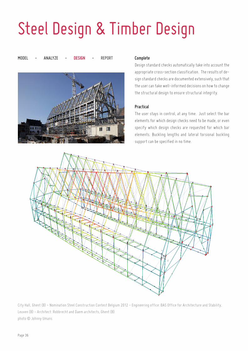
city hall, ghent (b) - nomination Steel construction contest belgium 2012 - engineering office: baS office for architecture and Stability,
leuven (b) - architect: robbrecht and Daem architects, ghent (b)
photo © Johnny umans
Complete
Design standard checks automatically take into account the
appropriate cross-section classification. the results of de-
sign standard checks are documented extensively, such that
the user can take well-informed decisions on how to change
the structural design to ensure structural integrity.
Practical
the user stays in control, at any time. Just select the bar
elements for which design checks need to be made, or even
specify which design checks are requested for which bar
elements. buckling lengths and lateral torsional buckling
support can be specified in no time.
Steel Design & Timber Design
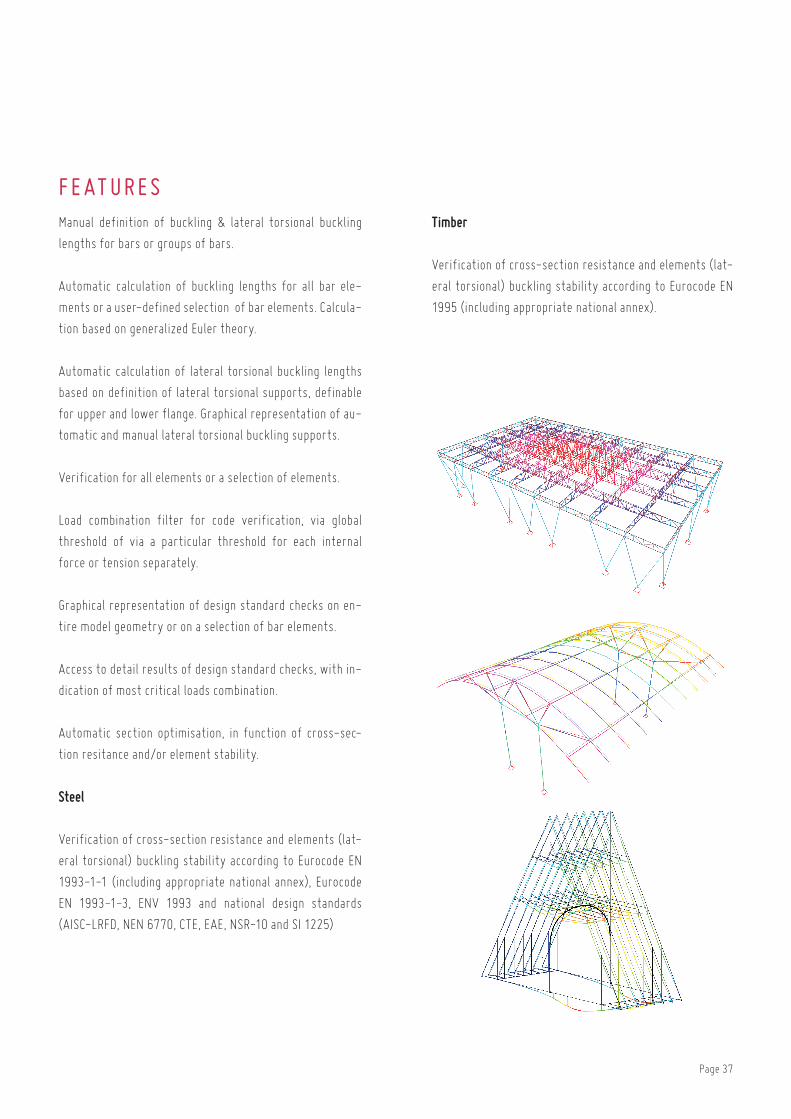
Page 37
F e at ur e sManual definition of buckling & lateral torsional buckling
lengths for bars or groups of bars.
automatic calculation of buckling lengths for all bar ele-
ments or a user-defined selection of bar elements. calcula-
tion based on generalized euler theory.
automatic calculation of lateral torsional buckling lengths
based on definition of lateral torsional supports, definable
for upper and lower flange. graphical representation of au-
tomatic and manual lateral torsional buckling supports.
Verification for all elements or a selection of elements.
load combination filter for code verification, via global
threshold of via a particular threshold for each internal
force or tension separately.
graphical representation of design standard checks on en-
tire model geometry or on a selection of bar elements.
access to detail results of design standard checks, with in-
dication of most critical loads combination.
automatic section optimisation, in function of cross-sec-
tion resitance and/or element stability.
Steel
Verification of cross-section resistance and elements (lat-
eral torsional) buckling stability according to eurocode en
1993-1-1 (including appropriate national annex), eurocode
en 1993-1-3, enV 1993 and national design standards
(aiSc-lrfD, nen 6770, cte, eae, nSr-10 and Si 1225)
Timber
Verification of cross-section resistance and elements (lat-
eral torsional) buckling stability according to eurocode en
1995 (including appropriate national annex).
Page 38
Model - AnAlyze - Design - RepoRt
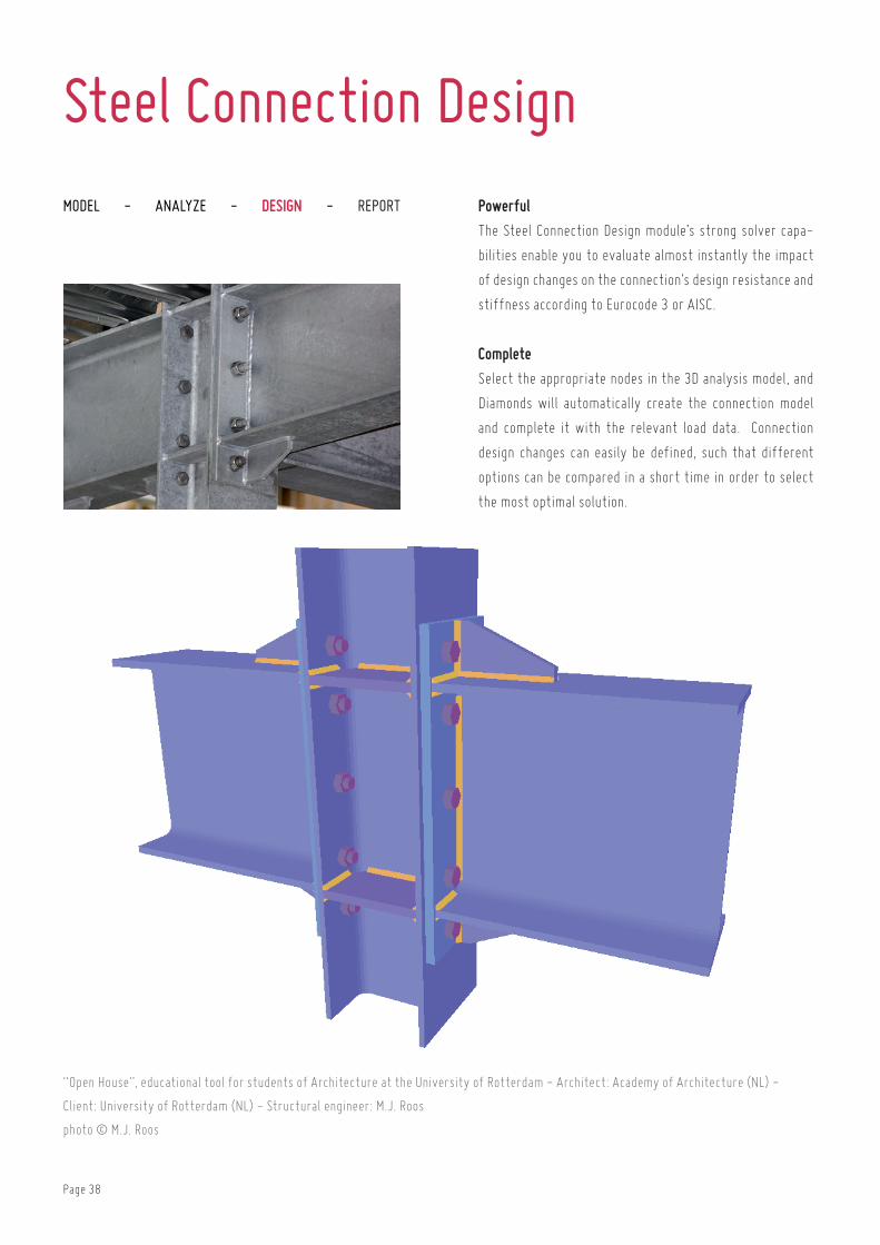
“open house”, educational tool for students of architecture at the university of rotterdam - architect: academy of architecture (nl) -
client: university of rotterdam (nl) - Structural engineer: M.J. roos
photo © M.J. roos
Powerful
the Steel connection Design module’s strong solver capa-
bilities enable you to evaluate almost instantly the impact
of design changes on the connection’s design resistance and
stiffness according to eurocode 3 or aiSc.
Complete
Select the appropriate nodes in the 3D analysis model, and
Diamonds will automatically create the connection model
and complete it with the relevant load data. connection
design changes can easily be defined, such that different
options can be compared in a short time in order to select
the most optimal solution.
Steel Connection Design

Page 39
F e at ur e slimit state design of bolted and welded connections, inte-
grated with global limit state design of portal frames.
evaluation of model design stiffness diagram and feedback
to Diamonds model for limit state design of structural steel
frames.
optimisation of bolt positions. calculation of weld strength.
fast identification of undersized and oversized components
through colour-coding on connection geometry of each
component’s level of exhaustion.
creation of plan views including annotation. export capabil-
ity to DXf.
Moment connectionsextensive range of connection types: beam-column, beam-
column-beam, beam-beam, column base, beam-beam with
bolted plate on flanges and/or web.
choice between wide range of stiffeners: end plate, end
plate stiffener, web stiffener, backing plate, web plate,
haunch, base plate with cramps, bolted plate on beam flange
or web, connection angle, ...
calculation of design resistance for bending moment, shear
force, normal force and rotational stiffness for fully re-
straint and partially restraind connections according to eu-
rocode en 1993-1-8 , aiSc-lrfD and iS800.
Shear connectionsextensive range of connection types: beam-column, beam-
column-beam, beam-beam with fin plate, flexible end plate
or bolted angles.
calculation of design resistance for shear force and normal
force for shear connections according to eurocode en 1993-
1-8 and aiSc-lrfD.
Hollow structural section connectionsanalysis of tubular connections of type t, y, Dy, X, K, n, Kt &
DK (circularn rectangular and i cross-section).
calculation of axial force resistance and in- plane and out-
of-plane bending moment resistance, according to eurocode
en 1993-1-8 and aiSc-lrfD.

Page 40
Ut id nisi blandit nulla tempus vulputate et eget sem. Aenean eget magna tellus. Donec at mauris vel eros viverra lacinia. In hac habitasse
platea dictumst. Aliquam ornare, turpis non varius posuere, dolor nibh viverra dui, eu sollicitudin mi lectus sit amet metus. Praesent non arcu
nec est viverra eleifend. Quisque sed massa elit
Model - AnAlyze - design - RepoRt Practical
thanks to the unique Smart reporter, well-structured re-
ports can be designed quickly based on sub-reports. Simply
define the appropriate model orientation and visibility for
each individual sub-report, and create stunning reports
that simply speak for themselves!
Efficient
Definitions of report layouts are always saved along with
the Diamonds project. following any changes defined to the
Diamonds analysis model, a new report can be created im-
mediately using the previously defined reporting lay-out.
Smart Reporter

Page 41
F e at ur e sflexible report manager to control various sub-reports as-
sociated to a single Diamonds project.
Quick generation of report based on selection of available
sub-reports.
full interaction with the design analysis model during defi-
nition phase of sub-report lay-out.
layout of sub-reports is saved as part the Diamonds pro-
ject, allowing for an automatic re-creation of reports fol-
lowing parameter changes to the original Diamonds model.
reports can be saved electronically.
lay-out of sub-reports can be saved as templates, for re-
use with other Diamonds projects.
automatically generated and continuous table of contents
and paragraph numbers for sub-reports.
Page header and footer can be completed with custom text
and placeholders for file name, date, page number and com-
pany logo.
Page 42
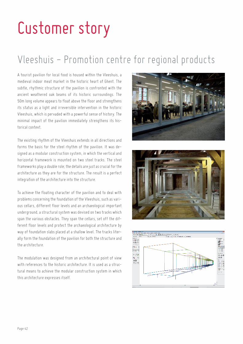
Customer story
a tourist pavilion for local food is housed within the Vleeshuis, a
medieval indoor meat market in the historic heart of ghent. the
subtle, rhythmic structure of the pavilion is confronted with the
ancient weathered oak beams of its historic surroundings. the
50m long volume appears to float above the floor and strengthens
its status as a light and irreversible intervention in the historic
Vleeshuis, which is pervaded with a powerful sense of history. the
minimal impact of the pavilion immediately strengthens its his-
torical context.
the existing rhythm of the Vleeshuis extends in all directions and
forms the basis for the steel rhythm of the pavilion. it was de-
signed as a modular construction system, in which the vertical and
horizontal framework is mounted on two steel tracks. the steel
frameworks play a double role; the details are just as crucial for the
architecture as they are for the structure. the result is a perfect
integration of the architecture into the structure.
to achieve the floating character of the pavilion and to deal with
problems concerning the foundation of the Vleeshuis, such as vari-
ous cellars, different floor levels and an archaeological important
underground, a structural system was devised on two tracks which
span the various obstacles. they span the cellars, set off the dif-
ferent floor levels and protect the archaeological architecture by
way of foundation slabs placed at a shallow level. the tracks liter-
ally form the foundation of the pavilion for both the structure and
the architecture.
the modulation was designed from an architectural point of view
with references to the historic architecture. it is used as a struc-
tural means to achieve the modular construction system in which
this architecture expresses itself.
Vleeshuis - Promotion centre for regional products

Page 43
Structural engineering office Mouton Studieburo Mouton is a structural design office that has acquired a special position within
the flemish architectural landscape as well as a steadily growing international reputation.
conducting a stability study for a design goes much further than simply calculating a given
situation. the office is ready to be involved in the architect’s very earliest design stage. its
main aim is to provide a stability study in which the interaction with the architect strength-
ens the design. the main endeavor of Studieburo Mouton, is to arrive together with the
designers at an intrinsically superior design process and structure. it is the intense coop-
eration between the architect and the engineer in which architecture and structure both
reinforce and challenge one another: this is designing together. in its design process, Stud-
ieburo Mouton’s task is to ensure that everything — ranging from the original artistic idea
to architectonic detail — is correctly and optimally covered. the structure and stability of a design are not merely calculated, but
designed. this method of work contrasts with the current view that the stability study is a phase that is separate from the architec-
tural design. the Studieburo Mouton absolutely does not envisage architecture and stability as separate entities but as a powerfully
expressed consolidation among partners that creates a superior final project. if the architect and the structural engineer are on the
same wavelength, the stability and structure of a design form a natural whole with the architecture.
BuildSoft client since 1989
BuildSoft software•Powerconnect
•Diamonds
•concrete
•12build
ContactStuDieburo Mouton
Koningin astridlaan 225
9000 gent
belgium
t +32 (0)9 221 49 65

Page 44
buildSoft is a belgian company specialized in software solutions for the structural design analysis of buildings and the calculation
of structures in reinforced concrete, steel and timber. buildSoft develops specialized calculation software according to the latest
eurocode, american and many local standards. we highly invest in the user-friendly and intuitive quality of our analysis software. the
software is meant for structural engineers, architects, contractors and building companies.
U s er-f r iend l yStarted in 1989 with the software concrete for continuous beams in concrete, buildSoft has developed several time-saving pro-
grams. from the beginning, the usability was a key feature. with the increased capacities of the computers, the buildSoft products
have evolved from a 1D program to the powerful and reliable 3D finite element software Diamonds.
V IP s upp or t“our unique mix of power, usability and service, appeals to the customers. we give you answers to your questions. because we have
a wide technical expertise on structural analysis and eurocodes” , says geert goossens, ceo of buildSoft.
Wor l d w idebuildSoft continues to innovate and invest in powerful user-friendly analysis software. the buildSoft software is being used today
in over 50 countries. with the help of resellers in Southern-europe, Scandinavia, South america, india, Middle east and china, there
are over 4000 buildSoft licenses in use. for example, with a product like Powerconnect, for steel connection design, buildSoft distin-
guishes itself from the market with both simplicity and performance and draws new customers worldwide.
R e f er en c e sexamples of projects calculated with buildSoft software and a complete list of our customers (engineering offices, contractors,
governments and education) can be found on our website:
http://www.buildsoft.eu/en/references
In f igur e s
26 75%2000 2200
customers use BuildSoft software in more than 50dif-
ferent countries
years of experience in structural design analysis and design
codes
licenses in use with customers
of the Diamonds customers have a
maintenance or sub-scription contract
student registra-tions every year for a free educational
license
4 000
About BuildSoft

Contact
Bui l d S o f thundelgemsesteenweg 244-1
be - 9820 Merelbeke
t +32 (0)9 252 66 28
www.buildsoft.eu
europe
S p a inConstrusoft S.L.c/ Doctor Vila no. 3, Planta baja
eS - 08740 Sant andreu de la barca
t +34 936327350
www.construsoft.com
P or t ug a lConstrusoft Ldaestrada do Paco do lumiar
campus do lumiar – edif D
Pt - 1649-038 lisboa
t +351 21 421 85 74
Gr e e c eConstrusoft Mitropoleos 43 - Metropolis center
gr - 15124 Maroussi
t +30 210 6120608
www.construsoft.com
Hung ar yConstrusoft Kfturomi u. 12.
hu - 1023 budapest
t +36-1-4384700
www.construsoft.com
I t a l yCSPFeavia Zuccherificio, 5/d
it - 35042 este
t +39 0429 602404
www.cspfea.net
S c and in a v i aEDR Medesoleif tronstads Plass 4
no - 1337 Sandvika
t +47 67 57 21 00
www.edrmedeso.no
Fr an c eFradan Structural 4, boulevard Michael faraday - Serris
fr - 77716 Marne la Vallée cedex 4
t +33 1 60 42 88 86
www.fradan.fr
Un i t e d K ingdomAthena Horizons Limited ashford
uK - tn24 9SD Kent
t +44 1233 330 055
www.athena-horizons.co.uk
Page 45

C h in aShanghai Co-base Steel Structuralroom 1601-1603, Jialuogonglu 368,
cn - 201800 Shanghai Jiading
t +86 21 54 15 01 02
Ind i a - Indon e s i a RamCaddsys Chennain 10, 7th avenue, ashoknagar
in - 600083 chennai
t +91 44 24 89 85 32
www.ramcadds.in
S ing ap or eRamCaddsys Singapore190 Middle road
Sg - 188979 Singapore
t +65 68 26 10 32
www.ramcadds.in
africa
I s r ae l Cubus Engineering Software Israelrozen str. 8
il - 43211 ra’anana (tel aviv)
t +97 29 74 89 713
www.cubus.co.il
B en inDjaouley Ingénieurs Conseils03 b.P. 4292
bn - 4292 cotonou
Bur und i - C ongoAGGLoBU2-3, avenue des usines
bu - bujumbura
t +257 22.29.05
Middle-east
asia
C o l ombi aConstrusoft LA SpA Delegación Bogotácalle 94a nº11 a-66 of 101
co - bogotá
t +57 1 601 3924
www.construsoft.com
C h i l eConstrusoft Chile SpAcarlos Silva Vildosola n° 1300 of 11
comuna de Providencia Santiago
t +562 22342978
www.construsoft.com
South americaP er uConstrusoft LA SAC Delegación Perúcalle larrabure y unanue nº 231 8º
piso, Distrito Jesús María - lima
t +48 61 8260 071
www.construsoft.com
Page 46

lateral buckling restraint - attaches - steel check - creep - charges climatiques - dynamic analysis - lateral buckling - brandweer-standsanalyse - timber - 1st order - verstijvers - buisverbinding - diseño de planos de armaduras - pandeo lateral - verbindingen
- shear connection - verificación - armatures longitudinales - pórtico - unión base columna - voorontwerp - unión tubular - haunch - con-
nexion moment - cimbras - vérification acier - unity check - Eurocode 2 - mesh - retaining wall - raidisseur - eurocode
3 - longitudes de pandeo - connections - aci - acero - 2nd ordre - portal frame - eurocode 8 - andamios - kip - dwarskracht-verbinding - bS - dalle de fondation - seismische analyse - armaduras longitudinales - BIM - gelaste verbinding - 2de orde - buckling
- funderingszool - poutre sur plusieurs appuis - maillage - malla - uniones - 2D raamwerken - fire resistance analysis - voiles
- cracked deformation - gescheurde doorbuiging - longueurs de flambement - pandeo - reinforcement -
unity check - cantonera - dynamische analyse - hout - ossatures 3D - koudgevormde profielen - placa de extreme - 1er orden
- continuous beam - connexion soudée - momentverbinding - praktische wapening - integrated connection design - ren-
forts au déversement - fluencia - estribos - déformation fissurée - ehe - beugels - eurocódigo 3 - platine de bout - análisis dinámico
- column base plate - kruip - rigid link - welded connection - charpente métallique - AISC - moment connections - estructuras
2D - kniestuk - assemblage métallique - 3D raamwerken - second ordre - beam grid - cargas climáticas - eurocode 2 - eurocode
5 - wall - deformación fisurada - lien rigide - enlace rígido - 2D frames - estructuras 3D - éléments finis - vloerplaat - steel connec-
tion - seismic analysis- scheurvorming - armatures pratiques - analyse sismique - nieve y viento - practical
reinforcement - charges mobiles - dalle - wapening - perfiles conformados en frío - Eurocode 3 - connexion tubulaire - unión a mo-
mento - 3D frames - treillis de poutres - roof truss - practical reinforcement design - portique - kipsteunen - análisis sísmico
- b.a.e.l - uniones atornilladas - bolts - Eurocode 8 - ossatures 2D - eindige elementen - losa de cimentación - restricciones para el pandeo lateral
- optimisation - wand - kniklengtes - end plate - dakspanten - kolomvoetverbinding - stirrups - acier - staalcon-
trole - cálculo de uniones integrado - paroi - dessin du plan de ferraillage - stiffeners - mobiele lasten - eurocódigo 8 - eurocódigo 5 - longitudinal
reinorcement - doorlopende liggers - rigidizador - beton armé - fluage - cte - connexion pied de poteau - langswapening
- connexions - hormigón - neige et vent - elementos finitos - armaduras - cold formed steel - jarret - uittekenen wapening - puente
grúa - analyse dynamique - flambement - keerwanden - optimisation - steel - cercha - 2º orden - slab on grade foundation - entramado de vi-
gas - Eurocode 5 - prédimensionnement - multi span beam - bouten - armatures - floor slab - poutre continue - pared - staal - 1er ordre - connexion cisaillement - losa - déversement - viga continua - predimensionering - 1ste orde - unión metálica - cM 66 - mad-
era - análisis resistencia al fuego - verbindingen - 2nd order - bois - eurocode 2 - profilés formés à froid - verificación acero - predesign
- unión soldada - fisuración - beton - muro de contención - optimalisatie - foundation pads - fissuration - concrete - aiSc
- hcSS - assemblage métallique - eurocode 3 - viga con varios apoyos - armaduras prácticas - balkenroosters - unión a cortante - buckling
length - boulons - cracking - Eurocode 8 - knik - eurocode 2 - radier - eindplaat - eurocódigo 2 - FEM - tornillos - nen - moving
loads - balk op meerdere steunpunten - cargas móviles - funderingsplaat - étriers - analyse resistance au feu
BuildSoftHundelgemsesteenweg 244-19820 Merelbeke (Belgium)T +32 (0)9 252 66 28 [email protected]