structural calculations site features
TRANSCRIPT
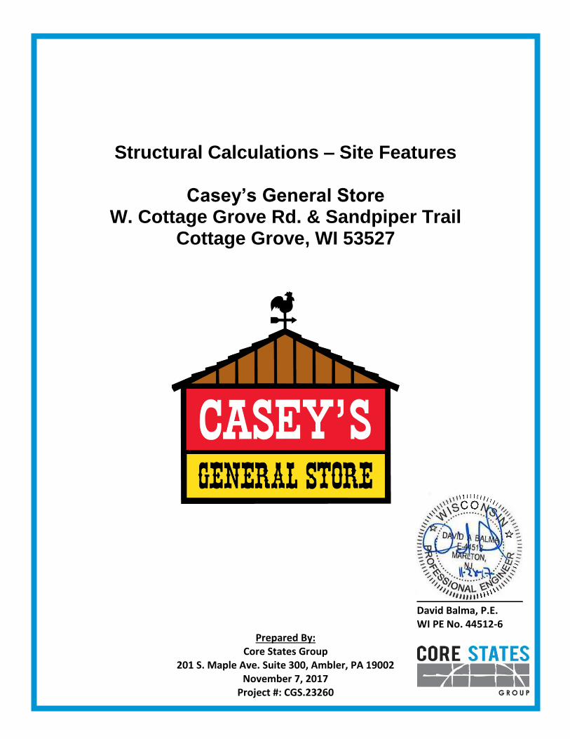
Structural Calculations – Site Features
Casey’s General Store
W. Cottage Grove Rd. & Sandpiper Trail Cottage Grove, WI 53527
___________________
David Balma, P.E. WI PE No. 44512-6
Prepared By: Core States Group
201 S. Maple Ave. Suite 300, Ambler, PA 19002 November 7, 2017
Project #: CGS.23260

Loading and Design
Building Code ........................................ 2009 International Building Code Wind ....................................................... Wind Loads per ASCE 7-05 Wind Speed ..................................... 90 mph (3-second gust) Building Risk Category .................... II Exposure ......................................... C Enclosure Classification .................. Open Internal Pressure Coefficient ........... N/A Seismic .................................................. Seismic Loads per ASCE 7-05 Building Risk Category .................... II Seismic Importance Factor ............. 1.0 Site Class ........................................ D (Assumed) Seismic Design Category ................ B SS / S1 .............................................. 0.107g / 0.044g SDS / SD1 .......................................... 0.114g / 0.070g Basic Seismic Force Resisting System ............................ Non-building Structure – Signs and Billboards Analysis Procedure ......................... Equivalent Lateral Force Procedure Design Base Shear ......................... (See Calculations) Soil Parameters Report By: ....................................... Not Provided Project # .......................................... N/A Report # .......................................... N/A Report Dated ................................... N/A Soil Bearing Capacity ...................... 1,500 psf (Assumed) Foundation Bearing Depth .............. 48” below lowest adjacent grade, Minimum. Modulus of Subgrade Reaction ....... N/A Vapor Barrier ................................... Required (see project specifications for thickness) Site Location W. Cottage Grove Rd. & Sandpiper Trail Cottage Grove, WI 53527
Region Map Location Map

Project Name : Cottage Grove, WI - Casey's General Store
Project Location : W. Cottage Grove Rd. & Sandpiper Trail
Cottage Grove, WI 53527
Project Number : CGS.23260
201 S. Maple Ave. Suite 300, Ambler, PA 19002
Wind Design Data Seismic Design Data
Code Reference = ASCE 7-05 Risk Category = II Spectral Response Acceleration Parameters
Ultimate Wind Speed, Vult = 115 mph Seismic Importance Factor = 1.00 Mapped SS = 0.107 g S1 = 0.044 g
Nominal Wind Speed, Vasd = 90 mph Site Class = D Design SDS = 0.114 g SD1 = 0.070 g
Exposure Category = C Seismic Design Category = B Response Modification Coefficient, R = 3.0
Building Risk Category = II Analysis Procedure = Equivalent Lateral Force Procedure
Basic Seismic Force Resisting System = Nonbuilding Structure - Signs and Billboards
Support Data
No. of Supports = 2
Support Spacing = 4 ft
No. of Foundations = 1
H1 H2 Weight Ult. Allowable
Ground Ground Mean of Wind Wind Seismic
Section Cabinet Width to Base to Top Area Height Section Force Force Force
No. (Y/N) Support Member (ft) (ft) (ft) (ft2) (ft) (lbs) (lbs) (lbs) (lbs)
1 No 0.667 0.0 13.583 9.056 6.792 652.0 338.5 203.1 24.8
2 Yes 10.625 13.583 16.583 31.875 15.083 622.1 1,229.2 737.5 23.7
3 No 1.0 16.583 17.25 0.667 16.917 32.0 25.7 15.4 1.2
4 Yes 9.417 17.25 24.667 69.84 20.958 1,403.6 2,898.2 1,738.9 53.4
5 - - - - - - - - - -
6 - - - - - - - - - -
7 - - - - - - - - - -
8 - - - - - - - - - -
Totals = 2,709.7 4,491.6 2,694.9 103.1
Base Moment = 82,015.1 49,209.1 1,665.2
Site Features - Sign Loads
-
-
-
-
W8x24
W8x24
W8x24
W8x24

Steel Column ENERCALC, INC. 1983-2017, Build:10.17.9.30, Ver:10.17.9.30Licensee : CORE STATES GROUPLic. # : KW-06008835
File = P:\CSDVM2~X\CJJ11O~5\AMEPS\SEV10W~K\Calcs\ST7XO2~I.EC6
Description : Sign Columns
Core States Group201 S. Maple Way, Ste. 300Ambler, PA 19002Ph: (215) 367-1320core-eng.com
Project Title: Cottage Grove, WI - Casey's General StoreEngineer: David A. Balma Project ID: CGS.23260
Printed: 8 NOV 2017, 10:07AM
Project Descr:
.Code ReferencesCalculations per AISC 360-05, IBC 2009, CBC 2010, ASCE 7-05Load Combinations Used : IBC 2009General Information
Steel Stress GradeTop Free, Bottom FixedAnalysis Method :
24.667Overall Column Height
ft
Top & Bottom FixityAllowable Strength
Fy : Steel Yieldksi29,000.0ksi
Steel Section Name : W8x24
36.0
ft
E : Elastic Bending ModulusY-Y (depth) axis :
X-X (width) axis :Unbraced Length for X-X Axis buckling = 24.667 ft, K = 2.1
Unbraced Length for Y-Y Axis buckling = 24.667 ft, K = 2.1
Brace condition for deflection (buckling) along columns :
.Applied Loads Service loads entered. Load Factors will be applied for calculations.
Column self weight included : 592.01 lbs * Dead Load FactorAXIAL LOADS . . .
Section 1: Axial Load at 6.792 ft, D = 0.3260 kSection 2: Axial Load at 15.083 ft, D = 0.3111 kSection 3: Axial Load at 16.917 ft, D = 0.0160 kSection 4: Axial Load at 20.958 ft, D = 0.7018 k
BENDING LOADS . . .Section 1: Lat. Point Load at 6.792 ft creating Mx-x, W = 0.1020, E = 0.0120 kSection 2: Lat. Point Load at 15.083 ft creating Mx-x, W = 0.3690, E = 0.0120 kSection 3: Lat. Point Load at 16.917 ft creating Mx-x, W = 0.0080, E = 0.0010 kSection 4: Lat. Point Load at 20.958 ft creating Mx-x, W = 0.870, E = 0.0270 k
.
X-X Slenderness Ratio kl/r > 200
DESIGN SUMMARY
PASS Max. Axial+Bending Stress Ratio = 0.8002
Location of max.above base 0.0 ft
1.947 k7.139 k
-24.627 k-ft
Load Combination +D+W
Load Combination +D+W
15.395 k-ft
Bending & Shear Check Results
PASS Maximum Shear Stress Ratio =
1.349 k
0.04822 : 1
Location of max.above base 0.0 ftAt maximum location values are . . .
: 1
At maximum location values are . . .
k
41.497 k-ft0.0 k-ft
Pa : AxialPn / Omega : AllowableMa-x : AppliedMn-x / Omega : AllowableMa-y : AppliedMn-y / Omega : Allowable
Va : AppliedVn / Omega : Allowable
Maximum Load Reactions . .
(see tab for all)
Top along X-X 0.0 kBottom along X-X 0.0 kTop along Y-Y 0.0 kBottom along Y-Y 1.349 k
Maximum Load Deflections . . .Along Y-Y 3.068 in at 24.667 ft above base
for load combination :+D+WAlong X-X 0.0 in at 0.0 ft above base
for load combination :
27.977.
Maximum Axial + Bending Stress Ratios Maximum Shear RatiosLoad Combination Stress Ratio Location Stress Ratio Status LocationStatus
Load Combination Results
D Only PASS PASS0.00 0.000 0.00 ftft0.273+D+W PASS PASS0.00 0.048 0.00 ftft0.800+D-W PASS PASS0.00 0.048 0.00 ftft0.800+1.016D+0.70E PASS PASS0.00 0.001 0.00 ftft0.290+1.016D-0.70E PASS PASS0.00 0.001 0.00 ftft0.290+D+0.750W PASS PASS0.00 0.036 0.00 ftft0.668+D-0.750W PASS PASS0.00 0.036 0.00 ftft0.668+1.012D+0.5250E PASS PASS0.00 0.001 0.00 ftft0.285+1.012D-0.5250E PASS PASS0.00 0.001 0.00 ftft0.285

Steel Column ENERCALC, INC. 1983-2017, Build:10.17.9.30, Ver:10.17.9.30Licensee : CORE STATES GROUPLic. # : KW-06008835
File = P:\CSDVM2~X\CJJ11O~5\AMEPS\SEV10W~K\Calcs\ST7XO2~I.EC6
Description : Sign Columns
Core States Group201 S. Maple Way, Ste. 300Ambler, PA 19002Ph: (215) 367-1320core-eng.com
Project Title: Cottage Grove, WI - Casey's General StoreEngineer: David A. Balma Project ID: CGS.23260
Printed: 8 NOV 2017, 10:07AM
Project Descr:
Maximum Axial + Bending Stress Ratios Maximum Shear RatiosLoad Combination Stress Ratio Location Stress Ratio Status LocationStatus
Load Combination Results
+0.60D+W PASS PASS0.00 0.048 0.00 ftft0.675+0.60D-W PASS PASS0.00 0.048 0.00 ftft0.675
.k k-ft
Note: Only non-zero reactions are listed.
Load CombinationX-X Axis Reaction Y-Y Axis ReactionAxial Reaction
@ Base @ Top@ Base @ Base @ Top
Maximum Reactions
@ Base @ Base@ Top @ TopMx - End Moments My - End Moments
D Only 1.947+D+W 1.947 1.349 -24.627+D-W 1.947 -1.349 24.627+D+0.70E 1.947 0.036 -0.592+D-0.70E 1.947 -0.036 0.592+D+0.750W 1.947 1.012 -18.470+D-0.750W 1.947 -1.012 18.470+D+0.5250E 1.947 0.027 -0.444+D-0.5250E 1.947 -0.027 0.444+0.60D+W 1.168 1.349 -24.627+0.60D-W 1.168 -1.349 24.627+0.60D+0.70E 1.168 0.036 -0.592+0.60D-0.70E 1.168 -0.036 0.592W Only 1.349 -24.627-W -1.349 24.627E Only 0.052 -0.845E Only * -1.0 -0.052 0.845
k k-ftItem
X-X Axis Reaction Y-Y Axis ReactionAxial Reaction@ Base @ Top@ Base @ Base @ Top
Extreme Reactions
Extreme Value @ Base @ Base@ Top @ TopMx - End Moments My - End Moments
MaximumAxial @ Base 1.947Minimum" 1.349 -24.627MaximumReaction, X-X Axis Base 1.947Minimum" 1.947MaximumReaction, Y-Y Axis Base 1.947 1.349 -24.627Minimum" 1.947 -1.349 24.627MaximumReaction, X-X Axis Top 1.947Minimum" 1.947MaximumReaction, Y-Y Axis Top 1.947Minimum" 1.947MaximumMoment, X-X Axis Base 1.947 -1.34924.627 24.627Minimum" 1.947 1.349-24.627 -24.627MaximumMoment, Y-Y Axis Base 1.947Minimum" 1.947MaximumMoment, X-X Axis Top 1.947Minimum" 1.947MaximumMoment, Y-Y Axis Top 1.947Minimum" 1.947
.Maximum Deflections for Load CombinationsMax. X-X Deflection Max. Y-Y Deflection DistanceLoad Combination Distance
D Only 0.0000 0.000 0.000 ftft inin 0.000+D+W 0.0000 3.068 24.667 ftft inin 0.000+D-W 0.0000 -3.068 24.667 ftft inin 0.000+D+0.70E 0.0000 0.071 24.667 ftft inin 0.000+D-0.70E 0.0000 -0.071 24.667 ftft inin 0.000+D+0.750W 0.0000 2.301 24.667 ftft inin 0.000+D-0.750W 0.0000 -2.301 24.667 ftft inin 0.000+D+0.5250E 0.0000 0.053 24.667 ftft inin 0.000+D-0.5250E 0.0000 -0.053 24.667 ftft inin 0.000+0.60D+W 0.0000 3.068 24.667 ftft inin 0.000+0.60D-W 0.0000 -3.068 24.667 ftft inin 0.000

Steel Column ENERCALC, INC. 1983-2017, Build:10.17.9.30, Ver:10.17.9.30Licensee : CORE STATES GROUPLic. # : KW-06008835
File = P:\CSDVM2~X\CJJ11O~5\AMEPS\SEV10W~K\Calcs\ST7XO2~I.EC6
Description : Sign Columns
Core States Group201 S. Maple Way, Ste. 300Ambler, PA 19002Ph: (215) 367-1320core-eng.com
Project Title: Cottage Grove, WI - Casey's General StoreEngineer: David A. Balma Project ID: CGS.23260
Printed: 8 NOV 2017, 10:07AM
Project Descr:
Maximum Deflections for Load CombinationsMax. X-X Deflection Max. Y-Y Deflection DistanceLoad Combination Distance
+0.60D+0.70E 0.0000 0.071 24.667 ftft inin 0.000+0.60D-0.70E 0.0000 -0.071 24.667 ftft inin 0.000W Only 0.0000 3.068 24.667 ftft inin 0.000-W 0.0000 -3.068 24.667 ftft inin 0.000E Only 0.0000 0.101 24.667 ftft inin 0.000E Only * -1.0 0.0000 -0.100 24.501 ftft inin 0.000
.Steel Section Properties : W8x24
R xx =
1.610
in
Depth = 7.930 in
R yy =
3.420
in Sw = 7.950 in^4K1 = 0.563 in Zy = 8.570 in^3Kdesign = 0.794 in
J = 0.346 in^4
Flange Width = 6.500 inFlange Thick
=0.400 in Zx = 23.100 in^3
Area=
7.080 in^2Weight = 24.000 plf
I xx = 82.70 in^4S xx = 20.90 in^3 Cw = 259.00 in^6Web Thick = 0.245 in
I yy = 18.300 in^4S yy = 5.630 in^3 Wno = 12.200 in^2
Qf = 4.710 in^3rts = 1.810 in Qw = 11.300 in^3Ycg = 0.000 in
rT = 0.000 in
Sketches

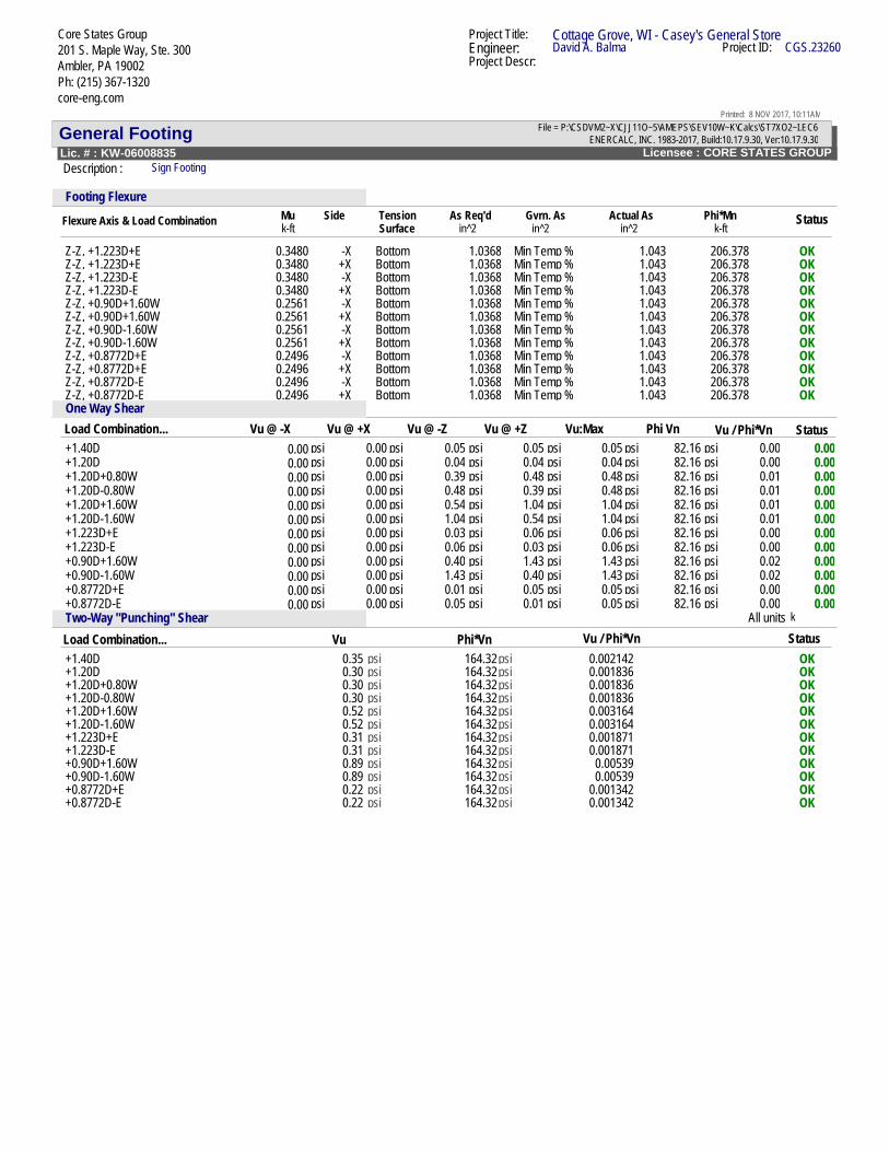
General Footing ENERCALC, INC. 1983-2017, Build:10.17.9.30, Ver:10.17.9.30Licensee : CORE STATES GROUPLic. # : KW-06008835
File = P:\CSDVM2~X\CJJ11O~5\AMEPS\SEV10W~K\Calcs\ST7XO2~I.EC6
Description : Sign Footing
Core States Group201 S. Maple Way, Ste. 300Ambler, PA 19002Ph: (215) 367-1320core-eng.com
Project Title: Cottage Grove, WI - Casey's General StoreEngineer: David A. Balma Project ID: CGS.23260
Printed: 8 NOV 2017, 10:11AM
Project Descr:
Code ReferencesCalculations per ACI 318-08, IBC 2009, CBC 2010, ASCE 7-05Load Combinations Used : IBC 2009General InformationMaterial Properties Soil Design Values
1.50
Analysis Settings
150.0ksiNo
ksfAllowable Soil Bearing ==
3.060.0
3,122.0145.0 = 0.30
Flexure = 0.90Shear =
Values
0.00180
4.0
Soil Passive Resistance (for Sliding)
1.01.0
=
Increases based on footing plan dimension
Add Pedestal Wt for Soil Pressure No:Use Pedestal wt for stability, mom & shear No:
Allowable pressure increase per foot of depth= ksf
when max. length or width is greater than= ft
:
=
Add Ftg Wt for Soil Pressure YesYes:Use ftg wt for stability, moments & shears
when footing base is below ft
pcf
Increase Bearing By Footing Weight= pcf
Min. Overturning Safety Factor=
: 1
Increases based on footing Depth0.750=
Soil/Concrete Friction Coeff.Ec : Concrete Elastic Modulus
Min. Sliding Safety Factor=
=
: 1
Footing base depth below soil surface ft=Allow press. increase per foot of depth ksf
=
=
=
Concrete Density
=
Min Allow % Temp Reinf.
ksif'c : Concrete 28 day strengthfy : Rebar Yield ksi
Min Steel % Bending Reinf.
#
DimensionsWidth parallel to X-X Axis 7.0 ftLength parallel to Z-Z Axis
=8.333 ft
=Pedestal dimensions...
px : parallel to X-X Axis inpz : parallel to Z-Z Axis inHeight =
=in
Footing Thickness=
48.0 in=
Rebar Centerline to Edge of Concrete...= inat Bottom of footing 3.0
Reinforcing
#
Bars parallel to X-X Axis
Reinforcing Bar Size=
8Number of Bars
=11.0
Bars parallel to Z-Z Axis
Reinforcing Bar Size = 8Number of Bars = 10.0
Bandwidth Distribution Check (ACI 15.4.4.2)Direction Requiring Closer SeparationBars along X-X Axis# Bars required within zone 91.3 %# Bars required on each side of zone 8.7 %
Applied Loads
2.710D Lr
ksf
L SP : Column LoadOB : Overburden =
kW E
M-zzV-x
== k
V-z k2.695 0.1031
M-xx =k-ft=k-ft49.209 1.665
H=

General Footing ENERCALC, INC. 1983-2017, Build:10.17.9.30, Ver:10.17.9.30Licensee : CORE STATES GROUPLic. # : KW-06008835
File = P:\CSDVM2~X\CJJ11O~5\AMEPS\SEV10W~K\Calcs\ST7XO2~I.EC6
Description : Sign Footing
Core States Group201 S. Maple Way, Ste. 300Ambler, PA 19002Ph: (215) 367-1320core-eng.com
Project Title: Cottage Grove, WI - Casey's General StoreEngineer: David A. Balma Project ID: CGS.23260
Printed: 8 NOV 2017, 10:11AM
Project Descr:
PASS n/a Sliding - X-X 0.0 k 0.0 k No SlidingPASS 5.558 Sliding - Z-Z 2.695 k 14.978 k +0.60D+W
DESIGN SUMMARY Design OKGoverning Load CombinationMin. Ratio Item Applied Capacity
PASS 0.9640 Soil Bearing 1.446 ksf 1.50 ksf +0.60D-W about X-X axisPASS 1.523 Overturning - X-X 59.989 k-ft 91.351 k-ft +0.60D+WPASS n/a Overturning - Z-Z 0.0 k-ft 0.0 k-ft No Overturning
PASS n/a Uplift 0.0 k 0.0 k No UpliftPASS 0.001930 Z Flexure (+X) 0.3984 k-ft/ft 206.378 k-ft/ft +1.40DPASS 0.001930 Z Flexure (-X) 0.3984 k-ft/ft 206.378 k-ft/ft +1.40DPASS 0.04118 X Flexure (+Z) 9.179 k-ft/ft 222.917 k-ft/ft +0.90D+1.60WPASS 0.04118 X Flexure (-Z) 9.179 k-ft/ft 222.917 k-ft/ft +0.90D-1.60WPASS n/a 1-way Shear (+X) 0.0 psi 82.158 psi n/aPASS 0.0 1-way Shear (-X) 0.0 psi 0.0 psi n/aPASS 0.01736 1-way Shear (+Z) 1.426 psi 82.158 psi +0.90D+1.60WPASS 0.01736 1-way Shear (-Z) 1.426 psi 82.158 psi +0.90D-1.60WPASS n/a 2-way Punching 0.8857 psi 82.158 psi +0.90D+1.60W
Detailed Results
Rotation Axis & ZeccXecc Actual Soil Bearing Stress @ Location Actual / AllowSoil Bearing
(in)Gross Allowable Bottom, -Z Top, +Z Left, -X Right, +X RatioLoad Combination...X-X, D Only 1.50 n/a0.6265 0.6265 n/a 0.4180.0n/aX-X, +D+W 1.50 n/a0.0 1.371 n/a 0.91419.70n/aX-X, +D-W 1.50 n/a1.371 0.0 n/a 0.914-19.70n/aX-X, +D+0.70E 1.50 n/a0.6087 0.6442 n/a 0.4300.4775n/aX-X, +D-0.70E 1.50 n/a0.6442 0.6087 n/a 0.430-0.4775n/aX-X, +D+0.750W 1.50 n/a0.07664 1.176 n/a 0.78414.775n/aX-X, +D-0.750W 1.50 n/a1.176 0.07664 n/a 0.784-14.775n/aX-X, +D+0.5250E 1.50 n/a0.6131 0.6398 n/a 0.4270.3582n/aX-X, +D-0.5250E 1.50 n/a0.6398 0.6131 n/a 0.427-0.3582n/aX-X, +0.60D+W 1.50 n/a0.0 1.446 n/a 0.96432.833n/aX-X, +0.60D-W 1.50 n/a1.446 0.0 n/a 0.964-32.833n/aX-X, +0.60D+0.70E 1.50 n/a0.3581 0.3936 n/a 0.2620.7959n/aX-X, +0.60D-0.70E 1.50 n/a0.3936 0.3581 n/a 0.262-0.7959n/aZ-Z, D Only 1.50 0.6265n/a n/a 0.6265 0.418n/a0.0Z-Z, +D+W 1.50 0.6265n/a n/a 0.6265 0.418n/a0.0Z-Z, +D-W 1.50 0.6265n/a n/a 0.6265 0.418n/a0.0Z-Z, +D+0.70E 1.50 0.6265n/a n/a 0.6265 0.418n/a0.0Z-Z, +D-0.70E 1.50 0.6265n/a n/a 0.6265 0.418n/a0.0Z-Z, +D+0.750W 1.50 0.6265n/a n/a 0.6265 0.418n/a0.0Z-Z, +D-0.750W 1.50 0.6265n/a n/a 0.6265 0.418n/a0.0Z-Z, +D+0.5250E 1.50 0.6265n/a n/a 0.6265 0.418n/a0.0Z-Z, +D-0.5250E 1.50 0.6265n/a n/a 0.6265 0.418n/a0.0Z-Z, +0.60D+W 1.50 0.3759n/a n/a 0.3759 0.251n/a0.0Z-Z, +0.60D-W 1.50 0.3759n/a n/a 0.3759 0.251n/a0.0Z-Z, +0.60D+0.70E 1.50 0.3759n/a n/a 0.3759 0.251n/a0.0Z-Z, +0.60D-0.70E 1.50 0.3759n/a n/a 0.3759 0.251n/a0.0
Rotation Axis &Overturning Stability
Load Combination... StatusOverturning Moment Resisting Moment Stability RatioX-X, D Only None 0.0 k-ft Infinity OKX-X, +D+W 59.989 k-ft 152.252 k-ft 2.538 OKX-X, +D+0.70E 1.454 k-ft 152.252 k-ft 104.70 OKX-X, +D+0.750W 44.992 k-ft 152.252 k-ft 3.384 OKX-X, +D+0.5250E 1.091 k-ft 152.252 k-ft 139.60 OKX-X, +0.60D+W 59.989 k-ft 91.351 k-ft 1.523 OKX-X, +0.60D+0.70E 1.454 k-ft 91.351 k-ft 62.820 OKZ-Z, D Only None 0.0 k-ft Infinity OKZ-Z, +D+W None 0.0 k-ft Infinity OKZ-Z, +D+0.70E None 0.0 k-ft Infinity OK

General Footing ENERCALC, INC. 1983-2017, Build:10.17.9.30, Ver:10.17.9.30Licensee : CORE STATES GROUPLic. # : KW-06008835
File = P:\CSDVM2~X\CJJ11O~5\AMEPS\SEV10W~K\Calcs\ST7XO2~I.EC6
Description : Sign Footing
Core States Group201 S. Maple Way, Ste. 300Ambler, PA 19002Ph: (215) 367-1320core-eng.com
Project Title: Cottage Grove, WI - Casey's General StoreEngineer: David A. Balma Project ID: CGS.23260
Printed: 8 NOV 2017, 10:11AM
Project Descr:
Rotation Axis &Overturning Stability
Load Combination... StatusOverturning Moment Resisting Moment Stability RatioZ-Z, +D+0.750W None 0.0 k-ft Infinity OKZ-Z, +D+0.5250E None 0.0 k-ft Infinity OKZ-Z, +0.60D+W None 0.0 k-ft Infinity OKZ-Z, +0.60D+0.70E None 0.0 k-ft Infinity OK
Force Application AxisSliding Stability All units k
Load Combination... StatusSliding Force Resisting Force Stability RatioX-X, D Only 0.0 k 20.962 k No Sliding OKX-X, +D+W 0.0 k 20.962 k No Sliding OKX-X, +D+0.70E 0.0 k 20.962 k No Sliding OKX-X, +D+0.750W 0.0 k 20.962 k No Sliding OKX-X, +D+0.5250E 0.0 k 20.962 k No Sliding OKX-X, +0.60D+W 0.0 k 16.577 k No Sliding OKX-X, +0.60D+0.70E 0.0 k 16.577 k No Sliding OKZ-Z, D Only 0.0 k 19.363 k No Sliding OKZ-Z, +D+W 2.695 k 19.363 k 7.185 OKZ-Z, +D+0.70E 0.07217 k 19.363 k 268.291 OKZ-Z, +D+0.750W 2.021 k 19.363 k 9.580 OKZ-Z, +D+0.5250E 0.05413 k 19.363 k 357.722 OKZ-Z, +0.60D+W 2.695 k 14.978 k 5.558 OKZ-Z, +0.60D+0.70E 0.07217 k 14.978 k 207.532 OK
Flexure Axis & Load Combination in^2 in^2 in^2 k-ftAs Req'd
Footing FlexureTension
k-ftActual As StatusMu Side
SurfaceGvrn. As Phi*Mn
X-X, +1.40D 0.5646 +Z Bottom 1.0368 Min Temp % 1.129 222.917 OKX-X, +1.40D 0.5646 -Z Bottom 1.0368 Min Temp % 1.129 222.917 OKX-X, +1.20D 0.4839 +Z Bottom 1.0368 Min Temp % 1.129 222.917 OKX-X, +1.20D 0.4839 -Z Bottom 1.0368 Min Temp % 1.129 222.917 OKX-X, +1.20D+0.80W 3.912 +Z Bottom 1.0368 Min Temp % 1.129 222.917 OKX-X, +1.20D+0.80W 2.944 -Z Top 1.0368 Min Temp % 1.129 222.917 OKX-X, +1.20D-0.80W 2.944 +Z Top 1.0368 Min Temp % 1.129 222.917 OKX-X, +1.20D-0.80W 3.912 -Z Bottom 1.0368 Min Temp % 1.129 222.917 OKX-X, +1.20D+1.60W 7.997 +Z Bottom 1.0368 Min Temp % 1.129 222.917 OKX-X, +1.20D+1.60W 5.714 -Z Top 1.0368 Min Temp % 1.129 222.917 OKX-X, +1.20D-1.60W 5.714 +Z Top 1.0368 Min Temp % 1.129 222.917 OKX-X, +1.20D-1.60W 7.997 -Z Bottom 1.0368 Min Temp % 1.129 222.917 OKX-X, +1.223D+E 0.6415 +Z Bottom 1.0368 Min Temp % 1.129 222.917 OKX-X, +1.223D+E 0.3447 -Z Bottom 1.0368 Min Temp % 1.129 222.917 OKX-X, +1.223D-E 0.3447 +Z Bottom 1.0368 Min Temp % 1.129 222.917 OKX-X, +1.223D-E 0.6415 -Z Bottom 1.0368 Min Temp % 1.129 222.917 OKX-X, +0.90D+1.60W 9.179 +Z Bottom 1.0368 Min Temp % 1.129 222.917 OKX-X, +0.90D+1.60W 4.531 -Z Top 1.0368 Min Temp % 1.129 222.917 OKX-X, +0.90D-1.60W 4.531 +Z Top 1.0368 Min Temp % 1.129 222.917 OKX-X, +0.90D-1.60W 9.179 -Z Bottom 1.0368 Min Temp % 1.129 222.917 OKX-X, +0.8772D+E 0.5021 +Z Bottom 1.0368 Min Temp % 1.129 222.917 OKX-X, +0.8772D+E 0.2054 -Z Bottom 1.0368 Min Temp % 1.129 222.917 OKX-X, +0.8772D-E 0.2054 +Z Bottom 1.0368 Min Temp % 1.129 222.917 OKX-X, +0.8772D-E 0.5021 -Z Bottom 1.0368 Min Temp % 1.129 222.917 OKZ-Z, +1.40D 0.3984 -X Bottom 1.0368 Min Temp % 1.043 206.378 OKZ-Z, +1.40D 0.3984 +X Bottom 1.0368 Min Temp % 1.043 206.378 OKZ-Z, +1.20D 0.3415 -X Bottom 1.0368 Min Temp % 1.043 206.378 OKZ-Z, +1.20D 0.3415 +X Bottom 1.0368 Min Temp % 1.043 206.378 OKZ-Z, +1.20D+0.80W 0.3415 -X Bottom 1.0368 Min Temp % 1.043 206.378 OKZ-Z, +1.20D+0.80W 0.3415 +X Bottom 1.0368 Min Temp % 1.043 206.378 OKZ-Z, +1.20D-0.80W 0.3415 -X Bottom 1.0368 Min Temp % 1.043 206.378 OKZ-Z, +1.20D-0.80W 0.3415 +X Bottom 1.0368 Min Temp % 1.043 206.378 OKZ-Z, +1.20D+1.60W 0.3415 -X Bottom 1.0368 Min Temp % 1.043 206.378 OKZ-Z, +1.20D+1.60W 0.3415 +X Bottom 1.0368 Min Temp % 1.043 206.378 OKZ-Z, +1.20D-1.60W 0.3415 -X Bottom 1.0368 Min Temp % 1.043 206.378 OKZ-Z, +1.20D-1.60W 0.3415 +X Bottom 1.0368 Min Temp % 1.043 206.378 OK
General Footing ENERCALC, INC. 1983-2017, Build:10.17.9.30, Ver:10.17.9.30Licensee : CORE STATES GROUPLic. # : KW-06008835
File = P:\CSDVM2~X\CJJ11O~5\AMEPS\SEV10W~K\Calcs\ST7XO2~I.EC6
Description : Sign Footing
Core States Group201 S. Maple Way, Ste. 300Ambler, PA 19002Ph: (215) 367-1320core-eng.com
Project Title: Cottage Grove, WI - Casey's General StoreEngineer: David A. Balma Project ID: CGS.23260
Printed: 8 NOV 2017, 10:11AM
Project Descr:
Flexure Axis & Load Combination in^2 in^2 in^2 k-ftAs Req'd
Footing FlexureTension
k-ftActual As StatusMu Side
SurfaceGvrn. As Phi*Mn
Z-Z, +1.223D+E 0.3480 -X Bottom 1.0368 Min Temp % 1.043 206.378 OKZ-Z, +1.223D+E 0.3480 +X Bottom 1.0368 Min Temp % 1.043 206.378 OKZ-Z, +1.223D-E 0.3480 -X Bottom 1.0368 Min Temp % 1.043 206.378 OKZ-Z, +1.223D-E 0.3480 +X Bottom 1.0368 Min Temp % 1.043 206.378 OKZ-Z, +0.90D+1.60W 0.2561 -X Bottom 1.0368 Min Temp % 1.043 206.378 OKZ-Z, +0.90D+1.60W 0.2561 +X Bottom 1.0368 Min Temp % 1.043 206.378 OKZ-Z, +0.90D-1.60W 0.2561 -X Bottom 1.0368 Min Temp % 1.043 206.378 OKZ-Z, +0.90D-1.60W 0.2561 +X Bottom 1.0368 Min Temp % 1.043 206.378 OKZ-Z, +0.8772D+E 0.2496 -X Bottom 1.0368 Min Temp % 1.043 206.378 OKZ-Z, +0.8772D+E 0.2496 +X Bottom 1.0368 Min Temp % 1.043 206.378 OKZ-Z, +0.8772D-E 0.2496 -X Bottom 1.0368 Min Temp % 1.043 206.378 OKZ-Z, +0.8772D-E 0.2496 +X Bottom 1.0368 Min Temp % 1.043 206.378 OKOne Way Shear
Vu @ +XLoad Combination... Vu @ -X Vu @ -Z Vu @ +Z Vu:Max Vu / Phi*VnPhi Vn Status+1.40D 0.00 0.00 0.05 0.05 0.05 82.16 0.00psipsipsipsipsipsi 0.00+1.20D 0.00 0.00 0.04 0.04 0.04 82.16 0.00psipsipsipsipsipsi 0.00+1.20D+0.80W 0.00 0.00 0.39 0.48 0.48 82.16 0.01psipsipsipsipsipsi 0.00+1.20D-0.80W 0.00 0.00 0.48 0.39 0.48 82.16 0.01psipsipsipsipsipsi 0.00+1.20D+1.60W 0.00 0.00 0.54 1.04 1.04 82.16 0.01psipsipsipsipsipsi 0.00+1.20D-1.60W 0.00 0.00 1.04 0.54 1.04 82.16 0.01psipsipsipsipsipsi 0.00+1.223D+E 0.00 0.00 0.03 0.06 0.06 82.16 0.00psipsipsipsipsipsi 0.00+1.223D-E 0.00 0.00 0.06 0.03 0.06 82.16 0.00psipsipsipsipsipsi 0.00+0.90D+1.60W 0.00 0.00 0.40 1.43 1.43 82.16 0.02psipsipsipsipsipsi 0.00+0.90D-1.60W 0.00 0.00 1.43 0.40 1.43 82.16 0.02psipsipsipsipsipsi 0.00+0.8772D+E 0.00 0.00 0.01 0.05 0.05 82.16 0.00psipsipsipsipsipsi 0.00+0.8772D-E 0.00 0.00 0.05 0.01 0.05 82.16 0.00psipsipsipsipsipsi 0.00
Vu / Phi*VnTwo-Way "Punching" Shear All units k
StatusVu Phi*VnLoad Combination...+1.40D 0.35 164.32 0.002142 OKpsipsi+1.20D 0.30 164.32 0.001836 OKpsipsi+1.20D+0.80W 0.30 164.32 0.001836 OKpsipsi+1.20D-0.80W 0.30 164.32 0.001836 OKpsipsi+1.20D+1.60W 0.52 164.32 0.003164 OKpsipsi+1.20D-1.60W 0.52 164.32 0.003164 OKpsipsi+1.223D+E 0.31 164.32 0.001871 OKpsipsi+1.223D-E 0.31 164.32 0.001871 OKpsipsi+0.90D+1.60W 0.89 164.32 0.00539 OKpsipsi+0.90D-1.60W 0.89 164.32 0.00539 OKpsipsi+0.8772D+E 0.22 164.32 0.001342 OKpsipsi+0.8772D-E 0.22 164.32 0.001342 OKpsipsi

16 in
11 in
Z
X
1
2
3
4
Plain Base Plate ConnectionBase Plate ThicknessBase Plate FyBearing Surface FpAnchor Bolt DiameterAnchor Bolt MaterialAnchor Bolt FuColumn ShapeSteel CodeConcrete Code
: 1.25 in: 36. ksi: 3.06 ksi: 1.25 in: F1554-36 : 58. ksi: W8x24 : AISC 13th:LRFD: ACI 318-08
Casey's - Edgerton, WI - Sign Base PlateBearing Pressure
Maximum BearingMax/Allowable Ratio
2.667
(ksi)
0.
2.667 ksi.871 IBC 16-6
(ABIF = 1.000)
Base Plate Stress Maximum StressMax/Allowable Ratio
39.992
(ksi)
.039
39.992 ksi.823 IBC 16-3 (b)
(ASIF = 1.000)
Anchor BoltsBolt X (in) Z (in) Tens.(k) Vx (k) Vz (k) Fnt (ksi) ft (ksi) Fnv (ksi) fv (ksi) Unity Combination
1 3.5 6. 22.407 0. 0. 32.6 18.262 17.4 N.A. .56 (T) IBC 16-6 (6)2 -3.5 6. 22.407 0. 0. 32.6 18.262 17.4 N.A. .56 (T) IBC 16-6 (6)3 3.5 -6. 0. 0. 0. 32.6 0. 17.4 N.A. 0. (T) IBC 16-1 (1)4 -3.5 -6. 0. 0. 0. 32.6 0. 17.4 N.A. 0. (T) IBC 16-1 (1)
Note: Fnt and Fnv shown above include phi factors.
LoadsP (k) Vx (k) Vz (k) Mx (k-ft) Mz (k-ft)
DLWLEL
1.35524.605.918
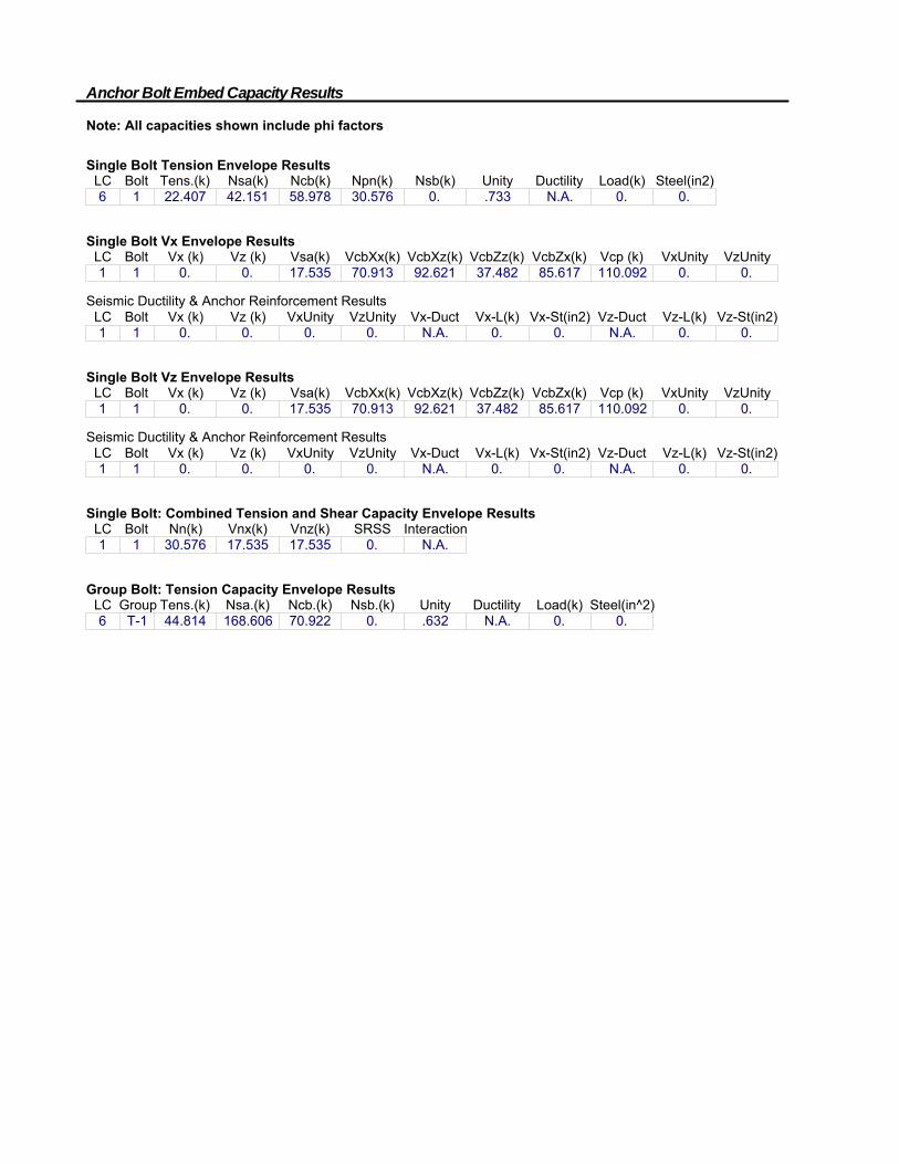
Anchor Bolt Embed Capacity Results
Note: All capacities shown include phi factors
Single Bolt Tension Envelope ResultsLC Bolt Tens.(k) Nsa(k) Ncb(k) Npn(k) Nsb(k) Unity Ductility Load(k) Steel(in2)6 1 22.407 42.151 58.978 30.576 0. .733 N.A. 0. 0.
Single Bolt Vx Envelope ResultsLC Bolt Vx (k) Vz (k) Vsa(k) VcbXx(k) VcbXz(k) VcbZz(k) VcbZx(k) Vcp (k) VxUnity VzUnity1 1 0. 0. 17.535 70.913 92.621 37.482 85.617 110.092 0. 0.
Seismic Ductility & Anchor Reinforcement ResultsLC Bolt Vx (k) Vz (k) VxUnity VzUnity Vx-Duct Vx-L(k) Vx-St(in2) Vz-Duct Vz-L(k) Vz-St(in2)1 1 0. 0. 0. 0. N.A. 0. 0. N.A. 0. 0.
Single Bolt Vz Envelope ResultsLC Bolt Vx (k) Vz (k) Vsa(k) VcbXx(k) VcbXz(k) VcbZz(k) VcbZx(k) Vcp (k) VxUnity VzUnity1 1 0. 0. 17.535 70.913 92.621 37.482 85.617 110.092 0. 0.
Seismic Ductility & Anchor Reinforcement ResultsLC Bolt Vx (k) Vz (k) VxUnity VzUnity Vx-Duct Vx-L(k) Vx-St(in2) Vz-Duct Vz-L(k) Vz-St(in2)1 1 0. 0. 0. 0. N.A. 0. 0. N.A. 0. 0.
Single Bolt: Combined Tension and Shear Capacity Envelope ResultsLC Bolt Nn(k) Vnx(k) Vnz(k) SRSS Interaction1 1 30.576 17.535 17.535 0. N.A.
Group Bolt: Tension Capacity Envelope ResultsLC Group Tens.(k) Nsa.(k) Ncb.(k) Nsb.(k) Unity Ductility Load(k) Steel(in^2)6 T-1 44.814 168.606 70.922 0. .632 N.A. 0. 0.

Project Name : Cottage Grove, WI - Casey's General Store
Project Location : W. Cottage Grove Rd. & Sandpiper Trail
Cottage Grove, WI 53527
Project Number : CGS.23260
201 S. Maple Ave. Suite 300, Ambler, PA 19002
Wind Design Data Seismic Design Data
Code Reference = ASCE 7-05 Risk Category = II Spectral Response Acceleration Parameters
Ultimate Wind Speed, Vult = 115 mph Seismic Importance Factor = 1.00 Mapped SS = 0.107 g S1 = 0.044 g
Nominal Wind Speed, Vasd = 90 mph Site Class = D Design SDS = 0.114 g SD1 = 0.070 g
Exposure Category = C Seismic Design Category = B Response Modification Coefficient, R = 3.0
Building Risk Category = II Analysis Procedure = Equivalent Lateral Force Procedure
Basic Seismic Force Resisting System = Nonbuilding Structure - Signs and Billboards
Support Data
No. of Supports = 1
Support Spacing = 1 ft (use "1" if only 1 support)
No. of Foundations = 1
H1 H2 Weight Ult. Allowable
Ground Ground Mean of Wind Wind Seismic
Section Cabinet Width to Base to Top Area Height Section Force Force Force
No. (Y/N) Support Member (ft) (ft) (ft) (ft2) (ft) (lbs) (lbs) (lbs) (lbs)
1 Yes 2.0 0.0 1.5 3.0 0.75 54.7 91.4 54.8 2.1
2 No 0.333 1.5 16.0 4.833 8.75 93.5 183.4 110.1 3.6
3 Yes 2.0 16.0 16.5 1.0 16.25 27.0 39.2 23.5 1.0
Totals = 175.2 314.0 188.4 6.7
Base Moment = 2,310.5 1,386.3 49.4
HSS 4x4x1/8
HSS 4x4x1/8
W8x24
Site Features - Light Pole Loads
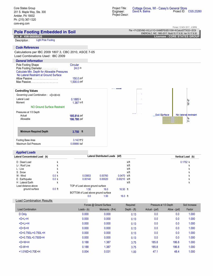
Pole Footing Embedded in Soil ENERCALC, INC. 1983-2017, Build:10.17.9.30, Ver:10.17.9.30
Licensee : CORE STATES GROUPLic. # : KW-06008835
File = P:\CSDVM2~X\CJJ11O~5\AMEPS\SEV10W~K\Calcs\ST7XO2~I.EC6
Description : Light Pole Footing
Core States Group
201 S. Maple Way, Ste. 300
Ambler, PA 19002
Ph: (215) 367-1320
core-eng.com
Project Title: Cottage Grove, WI - Casey's General StoreEngineer: David A. Balma Project ID: CGS.23260
Printed: 15 NOV 2017, 4:39PM
Project Descr:
Code References
Calculations per IBC 2009 1807.3, CBC 2010, ASCE 7-05
Load Combinations Used : IBC 2009
General InformationCircular
24.0
150.01,500.0
No Lateral Restraint at Ground Surface
Pole Footing ShapePole Footing Diameter . . . . . . . . . . . in
Allow Passive . . . . . . . . . . . . . . . . . . . . . . pcf
Max Passive . . . . . . . . . . . . . . . . . . . . . . psf
Calculate Min. Depth for Allowable Pressures
+D+W+HGoverning Load Combination :
Lateral Load 0.1885Moment 1.387 k-ft
Minimum Required Depth 3.750 ft
k
NO Ground Surface Restraint
Pressures at 1/3 Depth
Actual 185.814 psf
Allowable 186.780 psf
Controlling Values
ft^2Footing Base Area 3.142
Maximum Soil Pressure 0.05666 ksf
k
k
k
0.1752
k
k0.00760 0.0470
Applied Loads
k
Lateral Concentrated Load (k)
D : Dead Load
L : Live
Lr : Roof Live
S : Snow
W : Wind
E : Earthquake
H : Lateral Earth
Load distance above
0.0
0.0
0.0
k
k
k
k
k
k
k
ft
Lateral Distributed Loads (klf)
TOP of Load above ground surface
BOTTOM of Load above ground surface
0.03653
0.00140
1.50
0.0
k/ft
k/ft
k/ft
k/ft
k/ft
k/ft
k/ft
ft16.0 16.50ground surface
ft1.50 16.0
Vertical Load (k)
k0.00020 0.00210
Load Combination Results
Factor
Soil IncreaseForces @ Ground Surface
Load Combination
Required
Loads - (k) Moments - (ft-k) Depth - (ft)
Pressure at 1/3 Depth
Allow - (psf)Actual - (psf)
0.00.000 0.000D Only 0.13 1.0000.0
0.00.000 0.000+D+L+H 0.13 1.0000.0
0.00.000 0.000+D+Lr+H 0.13 1.0000.0
0.00.000 0.000+D+S+H 0.13 1.0000.0
0.00.000 0.000+D+0.750Lr+0.750L+H 0.13 1.0000.0
0.00.000 0.000+D+0.750L+0.750S+H 0.13 1.0000.0
185.80.188 1.387+D+W+H 3.75 1.000186.8
185.80.188 1.387+D-W+H 3.75 1.000186.8
47.10.004 0.031+1.016D+0.70E+H 1.00 1.00048.4
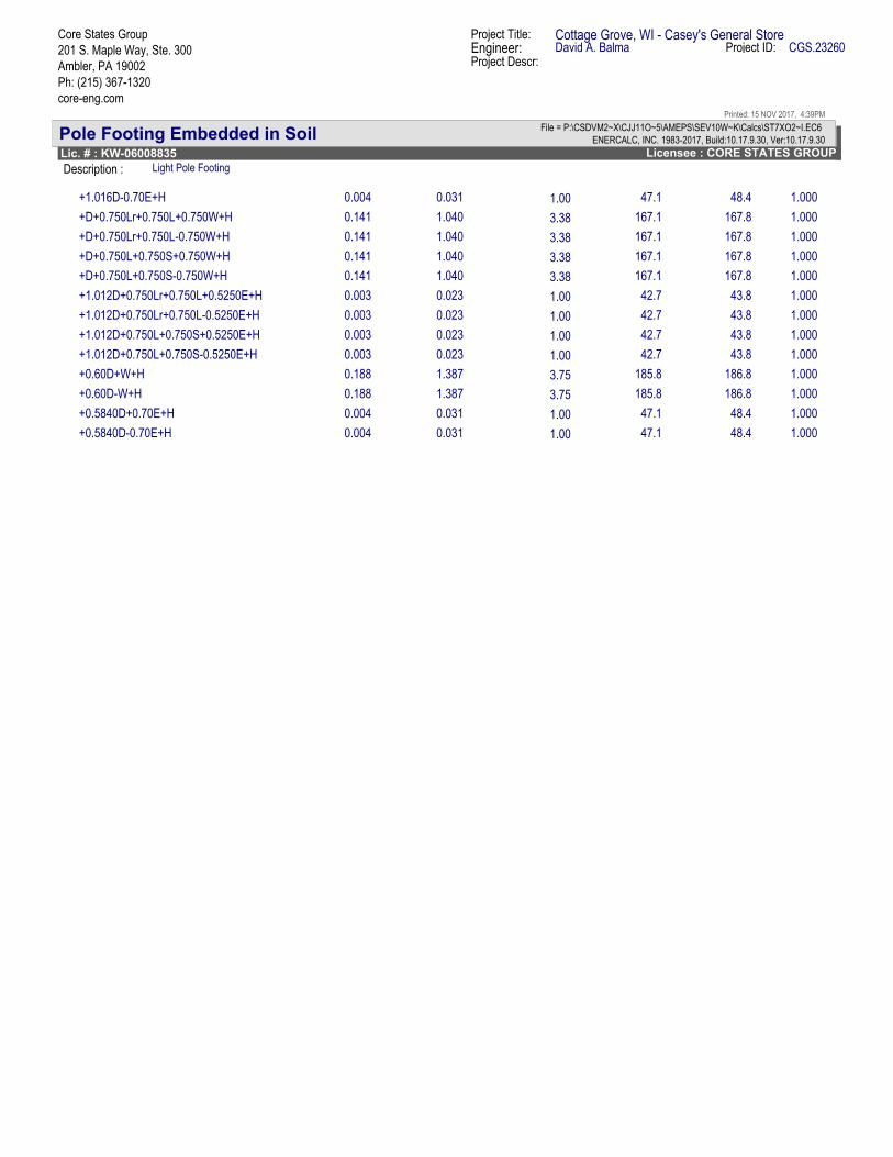
Pole Footing Embedded in Soil ENERCALC, INC. 1983-2017, Build:10.17.9.30, Ver:10.17.9.30
Licensee : CORE STATES GROUPLic. # : KW-06008835
File = P:\CSDVM2~X\CJJ11O~5\AMEPS\SEV10W~K\Calcs\ST7XO2~I.EC6
Description : Light Pole Footing
Core States Group
201 S. Maple Way, Ste. 300
Ambler, PA 19002
Ph: (215) 367-1320
core-eng.com
Project Title: Cottage Grove, WI - Casey's General StoreEngineer: David A. Balma Project ID: CGS.23260
Printed: 15 NOV 2017, 4:39PM
Project Descr:
47.10.004 0.031+1.016D-0.70E+H 1.00 1.00048.4
167.10.141 1.040+D+0.750Lr+0.750L+0.750W+H 3.38 1.000167.8
167.10.141 1.040+D+0.750Lr+0.750L-0.750W+H 3.38 1.000167.8
167.10.141 1.040+D+0.750L+0.750S+0.750W+H 3.38 1.000167.8
167.10.141 1.040+D+0.750L+0.750S-0.750W+H 3.38 1.000167.8
42.70.003 0.023+1.012D+0.750Lr+0.750L+0.5250E+H 1.00 1.00043.8
42.70.003 0.023+1.012D+0.750Lr+0.750L-0.5250E+H 1.00 1.00043.8
42.70.003 0.023+1.012D+0.750L+0.750S+0.5250E+H 1.00 1.00043.8
42.70.003 0.023+1.012D+0.750L+0.750S-0.5250E+H 1.00 1.00043.8
185.80.188 1.387+0.60D+W+H 3.75 1.000186.8
185.80.188 1.387+0.60D-W+H 3.75 1.000186.8
47.10.004 0.031+0.5840D+0.70E+H 1.00 1.00048.4
47.10.004 0.031+0.5840D-0.70E+H 1.00 1.00048.4