structural calculations retaining wall at bldg. k maintenance … · 2018-12-07 · structural...
TRANSCRIPT

Structural Calculations
Retaining Wall at Bldg. K Maintenance Yard
L.W. Cross Middle School
Amphitheater Public Schools
Tucson, AZ
Prepared for:
Breckenridge Group
SCI Project No. 18-196

SCI Project No. 18-196
Table of Contents
Design Criteria ......................................................................................................... 1
Wind Load Analysis ................................................................................................. 2
Wind Loads Diagram ............................................................................................... 4
Retaining Wall Analysis .......................................................................................... 5
Fence’s Post Revision ............................................................................................. 9
Retaining Wall Section .......................................................................................... 11
Base Plate Design .................................................................................................. 12
Base Plate Anchorage Design .............................................................................. 15
Scope
These calculations pertain only to the design of a cast-in-place concrete retaining wall with maximum retained height of
approximately 5-feet and anchorage design for fence posts spaced at approximately 8-feet on center. A steel fence
(designed and detailed by others) is supported at the top of
wall which is even with the finished grade of the maintenance yard slab. Design of the slab is specifically excluded from the scope of work.
Structural Concepts Inc. Page 1
Consulting Engineers Project 18-196
Phone (520) 721-2324 Fax (520) 885-3507
8230 E. Broadway, Suite W-7, Tucson, Arizona 85710
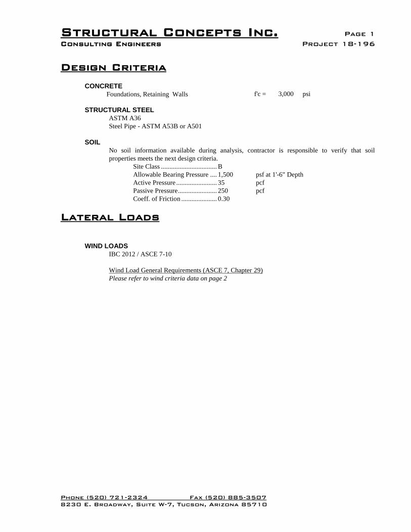
Design Criteria
CONCRETE
Foundations, Retaining Walls f'c = 3,000 psi
STRUCTURAL STEEL
ASTM A36
Steel Pipe - ASTM A53B or A501
SOIL
soilthatverifytoresponsibleiscontractoranalysis,No soil information available during
properties meets the next design criteria.
Site Class ................................. B
Allowable Bearing Pressure .... 1,500 psf at 1'-6" Depth
Active Pressure ........................ 35 pcf
Passive Pressure ....................... 250 pcf
Coeff. of Friction ..................... 0.30
Lateral Loads
WIND LOADS
IBC 2012 / ASCE 7-10
Wind Load General Requirements (ASCE 7, Chapter 29)
Please refer to wind criteria data on page 2
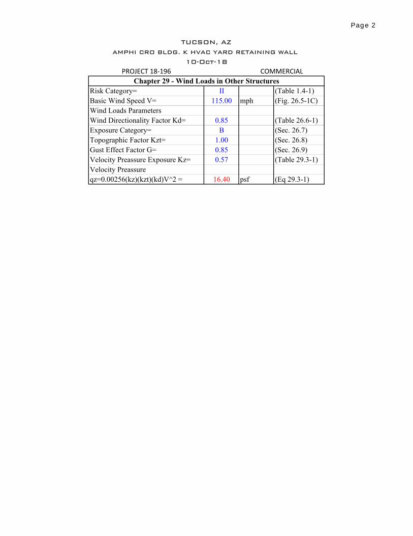
PROJECT 18-196
Risk Category= II (Table 1.4-1)
Basic Wind Speed V= 115.00 mph (Fig. 26.5-1C)
Wind Loads Parameters
Wind Directionality Factor Kd= 0.85 (Table 26.6-1)
Exposure Category= B (Sec. 26.7)
Topographic Factor Kzt= 1.00 (Sec. 26.8)
Gust Effect Factor G= 0.85 (Sec. 26.9)
Velocity Preassure Exposure Kz= 0.57 (Table 29.3-1)
Velocity Preassure
qz=0.00256(kz)(kzt)(kd)V^2 = 16.40 psf (Eq 29.3-1)
TUCSON, AZ
AMPHI CRO BLDG. K HVAC YARD RETAINING WALL
10-Oct-18
COMMERCIAL
Chapter 29 - Wind Loads in Other Structures
Page 2

Page 3
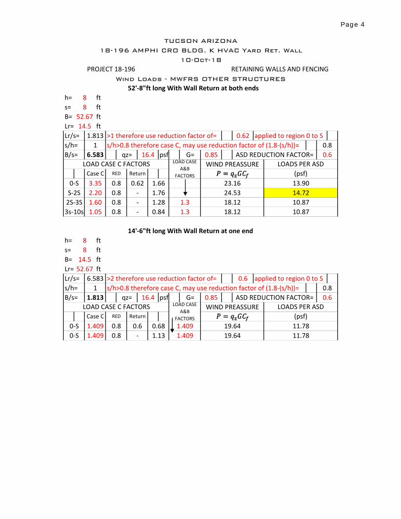
52'-8"ft long With Wall Return at both ends
h= ft
s= ft
B= ft
Lr= ft
Lr/s= >1 therefore use reduction factor of= applied to region 0 to S
s/h>0.8 therefore case C, may use reduction factor of (1.8-(s/h))=
B/s= psf
14'-6"ft long With Wall Return at one end
h= ft
s= ft
B= ft
Lr= ft
Lr/s= >2 therefore use reduction factor of= applied to region 0 to S
s/h>0.8 therefore case C, may use reduction factor of (1.8-(s/h))=
B/s= psf
19.64 11.78
0-S 1.409 0.8 - 1.13 1.409 19.64 11.78
0-S 1.409 0.8 0.6 0.68 1.409
0.85 ASD REDUCTION FACTOR= 0.6
LOAD CASE C FACTORS LOAD CASE
A&B
FACTORS
WIND PREASSURE LOADS PER ASD
Case C RED Return (psf)
1.813 qz= 16.4 G=
18.12 10.87
8
8
14.5
52.67
6.583 0.6
s/h= 1 0.8
3s-10s 1.05 0.8 - 0.84 1.3
8
8
52.67
14.5
1.813 0.62
s/h= 1 0.8
1.66 23.16 13.90
24.53 14.72
6.583 qz= 16.4 G= 0.85 ASD REDUCTION FACTOR= 0.6
LOAD CASE C FACTORS LOAD CASE
A&B
FACTORS
WIND PREASSURE LOADS PER ASD
Case C RED Return (psf)
PROJECT 18-196
Wind Loads - MWFRS OTHER STRUCTURES
TUCSON ARIZONA
18-196 AMPHI CRO BLDG. K HVAC Yard Ret. Wall
10-Oct-18
RETAINING WALLS AND FENCING
2S-3S 1.60 0.8 - 1.28 1.3 18.12 10.87
S-2S 2.20 0.8 - 1.76
0-S 3.35 0.8 0.62
� � ������ � �����
� � ������ � �����
Page 4
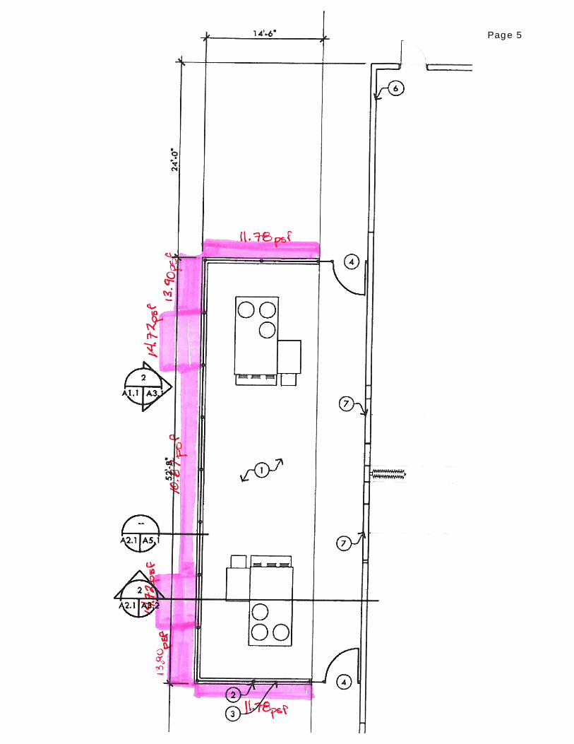
Page 5
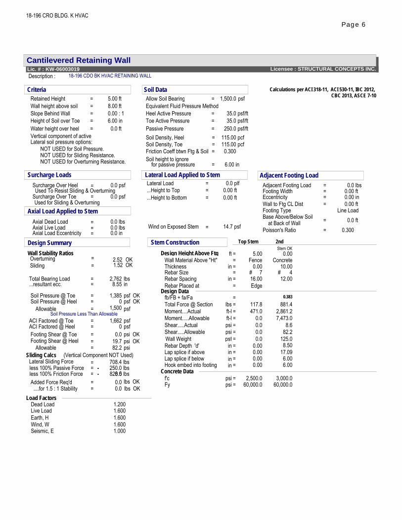
Cantilevered Retaining WallLicensee : STRUCTURAL CONCEPTS INC.Lic. # : KW-06003019
Description : 18-196 CDO BK HVAC RETAINING WALL
18-196 CRO BLDG. K HVAC
Calculations per ACI 318-11, ACI 530-11, IBC 2012,CBC 2013, ASCE 7-105.00
8.000.006.00
1,500.0
35.0
0.035.0 psf/ft
250.0
Criteria Soil DataRetained Height = ftWall height above soil = ft
Heel Active Pressure = psf/ft: 1Slope Behind WallHeight of Soil over Toe
=
inWater height over heel = ft
pcfpcf= 115.00
=
115.00
=
Soil Density, Heel
Toe Active Pressure =Passive Pressure = psf/ft
Allow Soil Bearing = psf
Soil Density, Toe
Soil height to ignoreFriction Coeff btwn Ftg & Soil = 0.300
Vertical component of activeLateral soil pressure options:
NOT USED for Soil Pressure.NOT USED for Sliding Resistance.NOT USED for Overturning Resistance. for passive pressure = 6.00 in
Equivalent Fluid Pressure Method
Surcharge Loads Adjacent Footing Load0.0 Lateral Load = 0.0 plf
0.0
0.00.00.0
Axial Load Applied to StemWall to Ftg CL Dist = 0.00 ft
Wind on Exposed Stem psf14.7=
Lateral Load Applied to StemSurcharge Over Heel = psf Adjacent Footing Load = 0.0 lbs
Axial Dead Load = lbs
Footing Type Line Load
Surcharge Over Toe psfFooting Width = 0.00 ft...Height to Top = 0.00 ftEccentricity = 0.00 in...Height to Bottom = 0.00 ft
Used To Resist Sliding & Overturning
Used for Sliding & Overturning
== 0.0 ftAxial Live Load =
Base Above/Below Soil
lbs
=
Axial Load Eccentricity = =Poisson's Ratio 0.300at Back of Wall
inDesign SummaryWall Stability RatiosOverturning = 2.52 OKSliding = 1.52 OK
Total Bearing Load = 2,762 lbs...resultant ecc. = 8.55 in
Soil Pressure @ Toe = 1,385 psf OKSoil Pressure @ Heel = 0 psf OK
Allowable = 1,500 psfSoil Pressure Less Than Allowable
ACI Factored @ Toe = 1,662 psfACI Factored @ Heel = 0 psfFooting Shear @ Toe = 0.0 psi OKFooting Shear @ Heel = 19.7 psi OK
Allowable = 82.2 psiSliding Calcs (Vertical Component NOT Used)
Lateral Sliding Force = 708.4 lbsless 100% Passive Forceless 100% Friction ForceAdded Force Req'd
....for 1.5 : 1 Stability =0.0=
828.50.0250.0
==
0.0
-lbslbslbs OKlbs OK
-
2ndStem OK
0.00Concrete
10.004#
12.00
0.383881.4
2,861.27,473.0
8.682.2
125.08.50
17.096.006.00
3,000.060,000.0 60,000.0
Stem Construction Top Stem
Design Height Above Ftg = 5.00ftWall Material Above "Ht" = FenceThickness = 0.00inRebar Size = # 7Rebar Spacing = 16.00inRebar Placed at = Edge
Design Datafb/FB + fa/Fa =Total Force @ Section = 117.8lbsMoment....Actual = 471.0ft-lMoment.....Allowable = 0.0ft-lShear.....Actual = 0.0psiShear.....Allowable = 0.0psi
Lap splice if above = 0.00in0.00in
Hook embed into footing 0.00=in
Wall Weight = 0.0
Lap splice if below =
psfRebar Depth 'd' = 0.00in
Concrete Dataf'c = 2,500.0psiFy =
Load FactorsDead Load 1.200Live Load 1.600Earth, H 1.600Wind, W 1.600Seismic, E 1.000
psi
Page 6
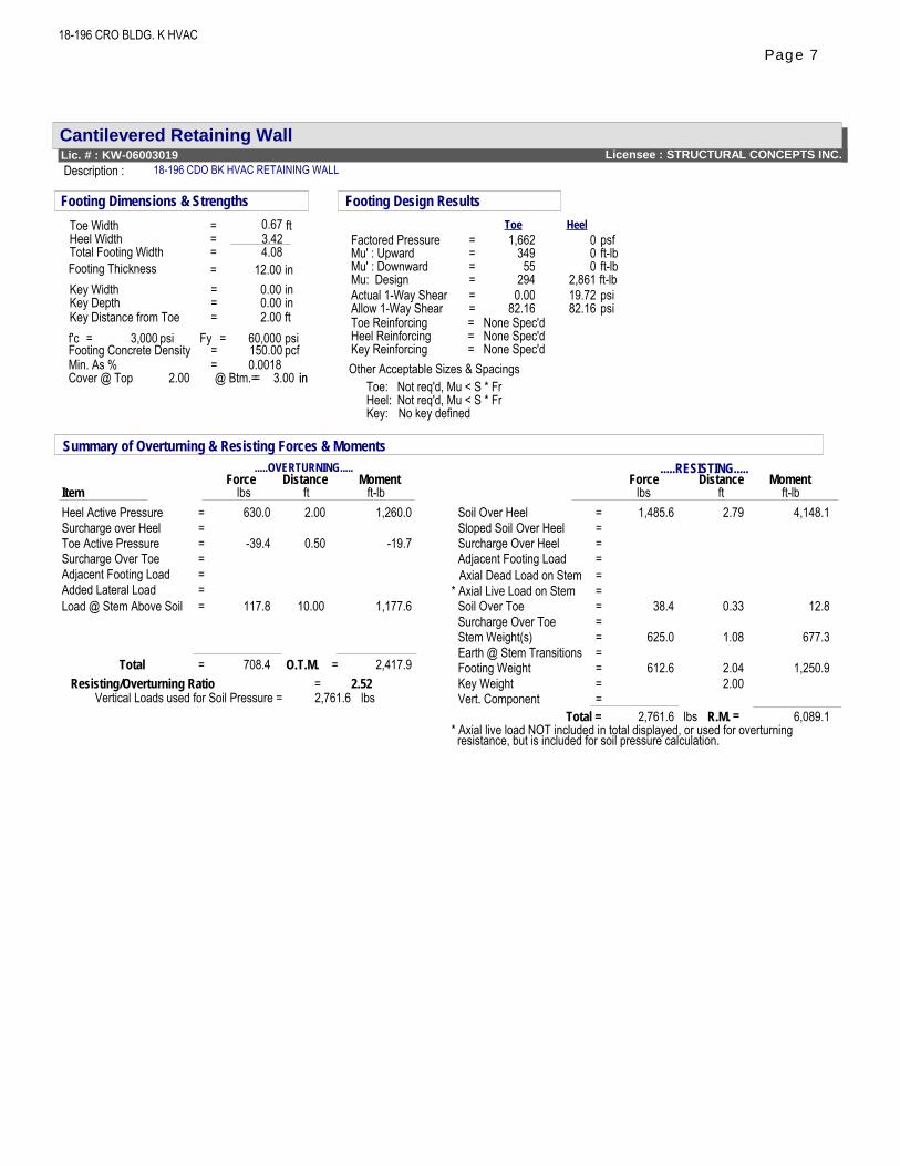
Cantilevered Retaining WallLicensee : STRUCTURAL CONCEPTS INC.Lic. # : KW-06003019
Description : 18-196 CDO BK HVAC RETAINING WALL
18-196 CRO BLDG. K HVAC
0.673.42
12.000.000.00
=Min. As % 0.0018
Footing Dimensions & Strengths
f'c = 3,000 psi
Toe Width = ftHeel Width =
Key Distance from ToeKey DepthKey Width = in
= in= 2.00
Footing Thickness = in4.08=
ft
Cover @ Top =2.00 in@ Btm.= 3.00 in
Total Footing Width
= 150.00 pcfFooting Concrete DensityFy = 60,000 psi
Footing Design Results
Key:
=
No key defined
Factored PressureMu' : UpwardMu' : DownwardMu: DesignActual 1-Way ShearAllow 1-Way Shear
Toe: Not req'd, Mu < S * FrNot req'd, Mu < S * Fr
= None Spec'd
==
===
1,66234955
2940.00
82.16
Heel:
000
2,86119.7282.16
HeelToepsfft-lbft-lbft-lbpsipsi
Heel Reinforcing = None Spec'd
Other Acceptable Sizes & SpacingsKey Reinforcing
Toe Reinforcing = None Spec'd
Summary of Overturning & Resisting Forces & Moments.....RESISTING..........OVERTURNING.....
Force Distance Moment Distance MomentItem
Force
Soil Over Heelft-lb
630.0 1,485.6lbs
1,260.0
-39.4Toe Active Pressure
2.00 2.79ftft
4,148.1=Heel Active Pressureft-lblbs
Sloped Soil Over Heel==Surcharge over Heel =
Surcharge Over Heel
=
=
Adjacent Footing Load=Adjacent Footing Load
Axial Dead Load on Stem ==* Axial Live Load on Stem
Soil Over ToeSurcharge Over Toe
Surcharge Over Toe
Load @ Stem Above Soil = 117.8 10.00 1,177.6
==
0.50 -19.7
38.4 0.33 12.8=
==
Stem Weight(s)=
625.0 1.08 677.3Earth @ Stem Transitions
=Footing Weight=
612.6 2.04 1,250.9Key Weight
=
2.00
Added Lateral Load
lbs
= 2,417.9
Vert. Component
Total
=2,761.6 6,089.1
* Axial live load NOT included in total displayed, or used for overturningresistance, but is included for soil pressure calculation.
Total = R.M.
=708.4 O.T.M.
=
Resisting/Overturning Ratio = 2.52Vertical Loads used for Soil Pressure = 2,761.6 lbs
Page 7
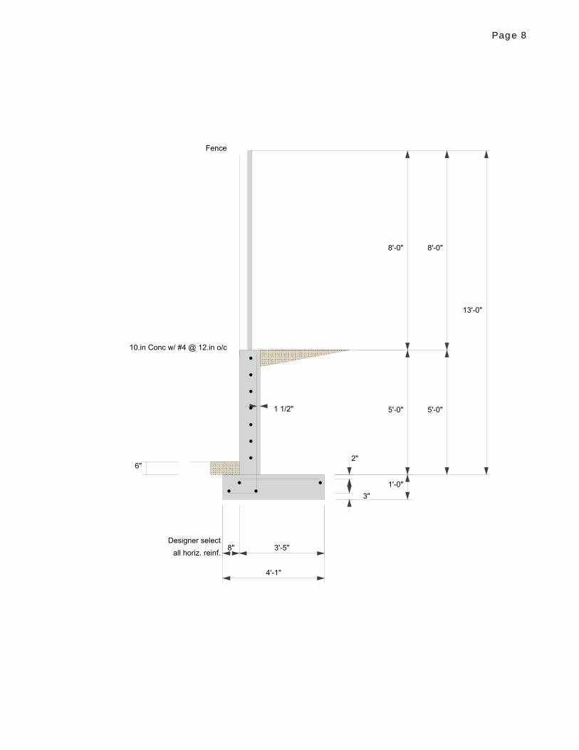
2"
3"
1 1/2"
Designer select
all horiz. reinf.
Fence
10.in Conc w/ #4 @ 12.in o/c
6"
1'-0"
8'-0"
5'-0" 5'-0"
8'-0"
13'-0"
8" 3'-5"
4'-1"
Page 8
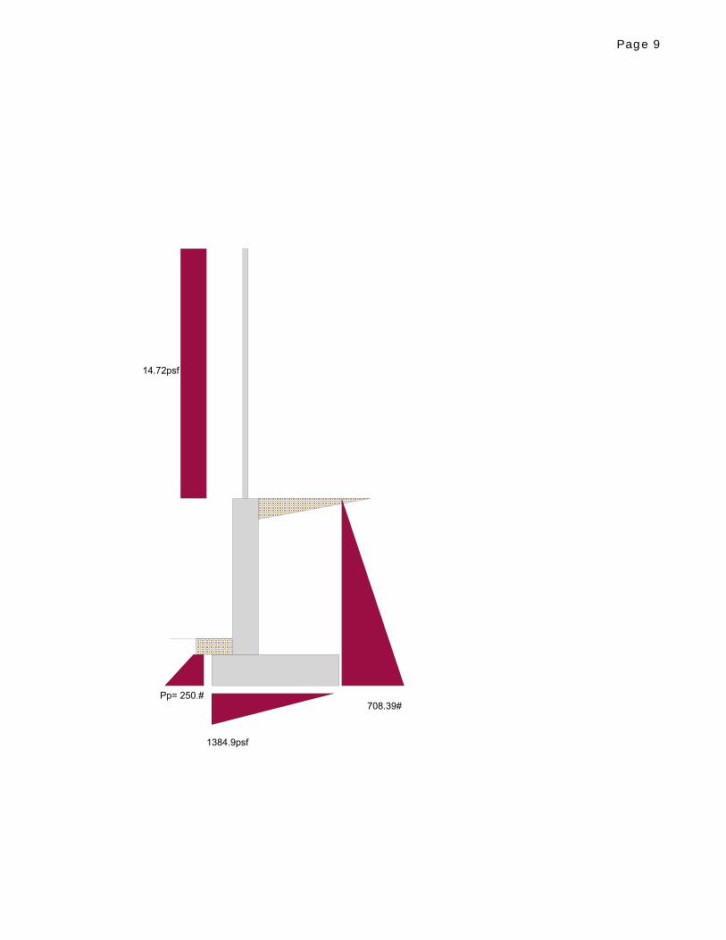
14.72psf
Pp= 250.#708.39#
1384.9psf
Page 9
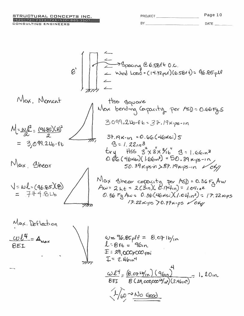
Page 10
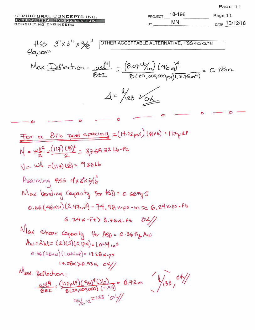
Page 11
Structural Concepts Inc8230 E. Broadway
Suite W-7
Tucson, Arizona.
Project
CRO Bldg. K Retaining WallJob Ref.
18-196
Section Sheet no./rev.
1
Calc. by
MNDate
10/17/2018Chk'd by
JMDate App'd by Date
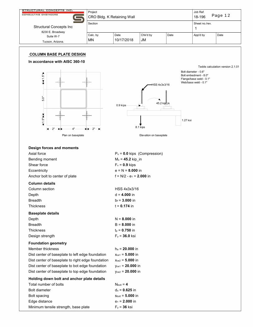
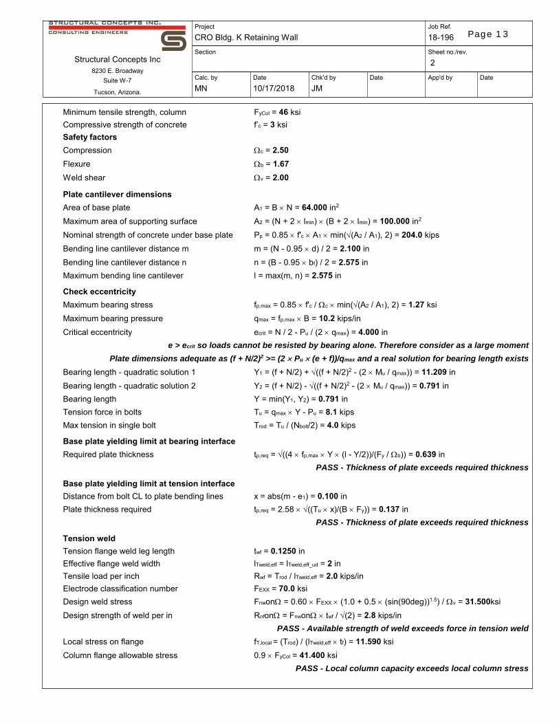
COLUMN BASE PLATE DESIGN
In accordance with AISC 360-10Tedds calculation version 2.1.01
2" 4" 2"
1.5
"5.
0"
1.5"
Plan on baseplate Elevation on baseplate
8.1 kips
1.27 ksi
45.2 kip_in0.9 kips
HSS 4x3x3/16
Bolt diameter - 0.6"Bolt embedment - 8.0"Flange/base weld - 0.1"Web/base weld - 0.1"
Design forces and moments
Axial force; Pu = 0.0 kips; (Compression)
Bending moment; Mu = 45.2 kip_in
Shear force; Fv = 0.9 kips
Eccentricity; e = N = 8.000 in
Anchor bolt to center of plate; f = N/2 - e1 = 2.000 in
Column details
Column section; HSS 4x3x3/16
Depth; d = 4.000 in
Breadth; bf = 3.000 in
Thickness; t = 0.174 in
Baseplate details
Depth; N = 8.000 in
Breadth; B = 8.000 in
Thickness; tp = 0.750 in
Design strength; Fy = 36.0 ksi
Foundation geometry
Member thickness; ha = 20.000 in
Dist center of baseplate to left edge foundation; xce1 = 5.000 in
Dist center of baseplate to right edge foundation; xce2 = 5.000 in
Dist center of baseplate to bot edge foundation; yce1 = 20.000 in
Dist center of baseplate to top edge foundation; yce2 = 20.000 in
Holding down bolt and anchor plate details
Total number of bolts; Nbolt = 4
Bolt diameter; do = 0.625 in
Bolt spacing; sbolt = 5.000 in
Edge distance; e1 = 2.000 in
Minimum tensile strength, base plate; Fy = 36 ksi
Page 12
Structural Concepts Inc8230 E. Broadway
Suite W-7
Tucson, Arizona.
Project
CRO Bldg. K Retaining WallJob Ref.
18-196
Section Sheet no./rev.
2
Calc. by
MNDate
10/17/2018Chk'd by
JMDate App'd by Date
Minimum tensile strength, column; FyCol = 46 ksi
Compressive strength of concrete; f’c = 3 ksi
Safety factors
Compression; c = 2.50
Flexure; b = 1.67
Weld shear; v = 2.00
Plate cantilever dimensions
Area of base plate; A1 = B N = 64.000 in2
Maximum area of supporting surface; A2 = (N + 2 lmin) (B + 2 lmin) = 100.000 in2
Nominal strength of concrete under base plate; Pp = 0.85 f'c A1 min((A2 / A1), 2) = 204.0 kips
Bending line cantilever distance m; m = (N - 0.95 d) / 2 = 2.100 in
Bending line cantilever distance n; n = (B - 0.95 bf) / 2 = 2.575 in
Maximum bending line cantilever; l = max(m, n) = 2.575 in
Check eccentricity
Maximum bearing stress; fp,max = 0.85 f'c / c min((A2 / A1), 2) = 1.27 ksi
Maximum bearing pressure; qmax = fp,max B = 10.2 kips/in
Critical eccentricity; ecrit = N / 2 - Pu / (2 qmax) = 4.000 in
e > ecrit so loads cannot be resisted by bearing alone. Therefore consider as a large moment
Plate dimensions adequate as (f + N/2)2 >= (2 Pu (e + f))/qmax and a real solution for bearing length exists
Bearing length - quadratic solution 1; Y1 = (f + N/2) + ((f + N/2)2 - (2 Mu / qmax)) = 11.209 in
Bearing length - quadratic solution 2; Y2 = (f + N/2) - ((f + N/2)2 - (2 Mu / qmax)) = 0.791 in
Bearing length; Y = min(Y1, Y2) = 0.791 in
Tension force in bolts; Tu = qmax Y - Pu = 8.1 kips
Max tension in single bolt; Trod = Tu / (Nbolt/2) = 4.0 kips
Base plate yielding limit at bearing interface
Required plate thickness; tp,req = ((4 fp,max Y (l - Y/2))/(Fy / b)) = 0.639 in
PASS - Thickness of plate exceeds required thickness
Base plate yielding limit at tension interface
Distance from bolt CL to plate bending lines; x = abs(m - e1) = 0.100 in
Plate thickness required; tp,req = 2.58 ((Tu x)/(B Fy)) = 0.137 in
PASS - Thickness of plate exceeds required thickness
Tension weld
Tension flange weld leg length; twf = 0.1250 in
Effective flange weld width; lTweld,eff = lTweld,eff_ud = 2 in
Tensile load per inch; Rwf = Trod / lTweld,eff = 2.0 kips/in
Electrode classification number; FEXX = 70.0 ksi
Design weld stress; Fnwon = 0.60 FEXX (1.0 + 0.5 (sin(90deg))1.5) / v = 31.500ksi
Design strength of weld per in; Rnfon = Fnwon twf / (2) = 2.8 kips/in
PASS - Available strength of weld exceeds force in tension weld
Local stress on flange; fT,local = (Trod) / (lTweld,eff tf) = 11.590 ksi
Column flange allowable stress; 0.9 FyCol = 41.400 ksi
PASS - Local column capacity exceeds local column stress
Page 13
Structural Concepts Inc8230 E. Broadway
Suite W-7
Tucson, Arizona.
Project
CRO Bldg. K Retaining WallJob Ref.
18-196
Section Sheet no./rev.
3
Calc. by
MNDate
10/17/2018Chk'd by
JMDate App'd by Date
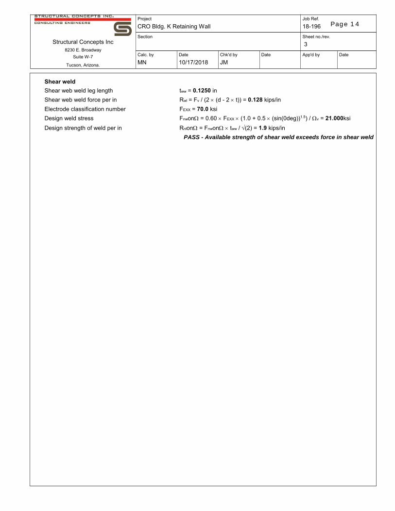
Shear weld
Shear web weld leg length; tww = 0.1250 in
Shear web weld force per in; Rwl = Fv / (2 (d - 2 t)) = 0.128 kips/in
Electrode classification number; FEXX = 70.0 ksi
Design weld stress; Fnwon = 0.60 FEXX (1.0 + 0.5 (sin(0deg))1.5) / v = 21.000ksi
Design strength of weld per in; Rnlon = Fnwon tww / (2) = 1.9 kips/in
PASS - Available strength of shear weld exceeds force in shear weld
Page 14
www.hilti.us Profis Anchor 2.7.9
Input data and results must be checked for agreement with the existing conditions and for plausibility!PROFIS Anchor ( c ) 2003-2009 Hilti AG, FL-9494 Schaan Hilti is a registered Trademark of Hilti AG, Schaan
Company:Specifier:Address:Phone I Fax:E-Mail:
Structural Concepts, Inc.Manuel Naves8230 E. Broadway Blvd, Suite W-75207212324 | [email protected]
Page:Project:Sub-Project I Pos. No.:Date:
1CRO Bldg. K Ret. Wall18-19610/17/2018
Specifier's comments:
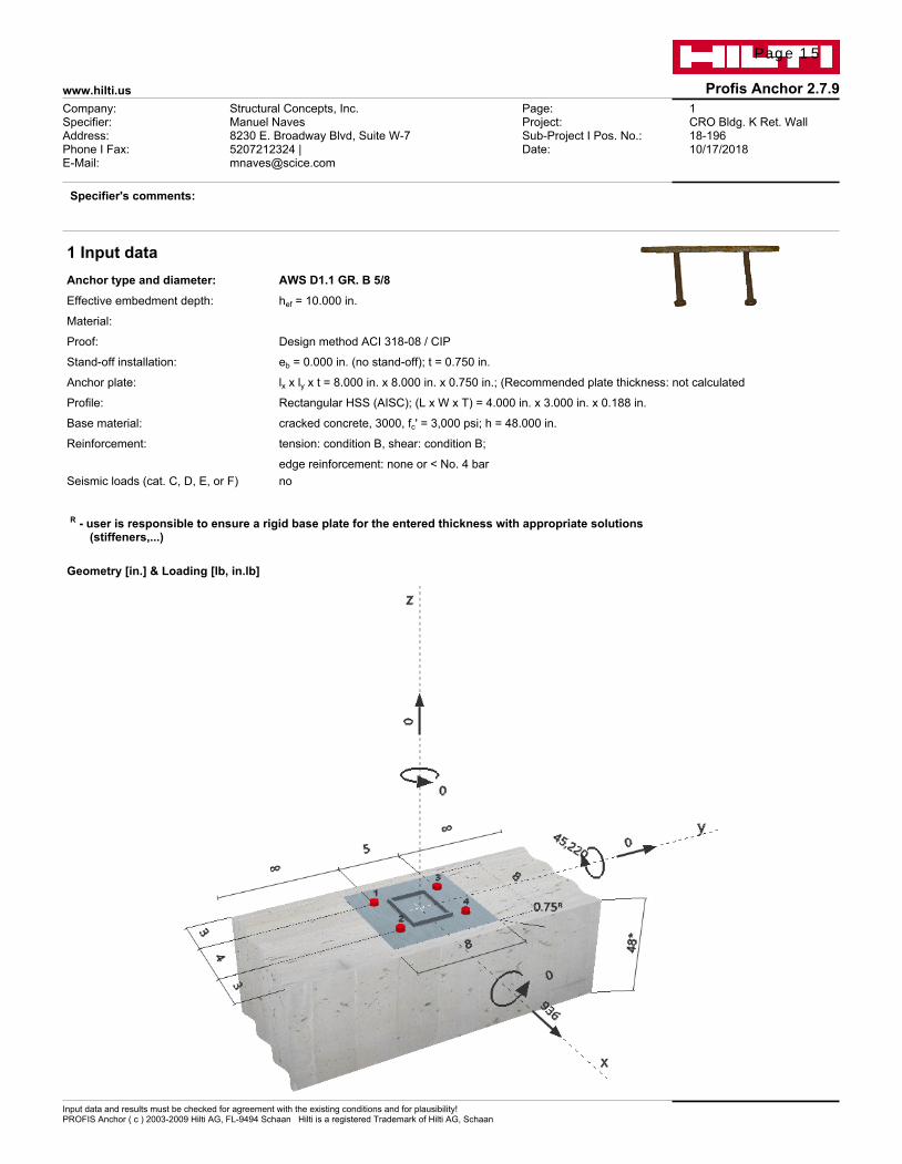
1 Input dataAnchor type and diameter: AWS D1.1 GR. B 5/8
Effective embedment depth: hef = 10.000 in.
Material:
Proof: Design method ACI 318-08 / CIP
Stand-off installation: eb = 0.000 in. (no stand-off); t = 0.750 in.
Anchor plate: lx x ly x t = 8.000 in. x 8.000 in. x 0.750 in.; (Recommended plate thickness: not calculated
Profile: Rectangular HSS (AISC); (L x W x T) = 4.000 in. x 3.000 in. x 0.188 in.
Base material: cracked concrete, 3000, fc' = 3,000 psi; h = 48.000 in.
Reinforcement: tension: condition B, shear: condition B;
edge reinforcement: none or < No. 4 barSeismic loads (cat. C, D, E, or F) no
R - user is responsible to ensure a rigid base plate for the entered thickness with appropriate solutions (stiffeners,...)
Geometry [in.] & Loading [lb, in.lb]
Page 15
www.hilti.us Profis Anchor 2.7.9
Input data and results must be checked for agreement with the existing conditions and for plausibility!PROFIS Anchor ( c ) 2003-2009 Hilti AG, FL-9494 Schaan Hilti is a registered Trademark of Hilti AG, Schaan
Company:Specifier:Address:Phone I Fax:E-Mail:
Structural Concepts, Inc.Manuel Naves8230 E. Broadway Blvd, Suite W-75207212324 | [email protected]
Page:Project:Sub-Project I Pos. No.:Date:
2CRO Bldg. K Ret. Wall18-19610/17/2018
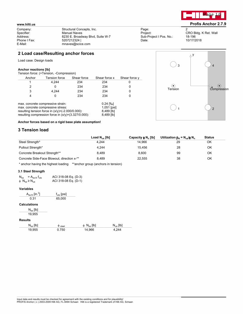
2 Load case/Resulting anchor forcesLoad case: Design loads
Anchor reactions [lb]Tension force: (+Tension, -Compression)
Anchor Tension force Shear force Shear force x Shear force y1 4,244 234 234 0
2 0 234 234 03 4,244 234 234 04 0 234 234 0
max. concrete compressive strain: 0.24 [‰] max. concrete compressive stress: 1,051 [psi]resulting tension force in (x/y)=(-2.000/0.000): 8,489 [lb]resulting compression force in (x/y)=(3.327/0.000): 8,489 [lb] Anchor forces based on a rigid base plate assumption!
Tension Compression
1 2
3 4
x
y
3 Tension load Load Nua [lb] Capacity f f f f Nn [lb] Utilization bbbbN = Nua/f f f f Nn Status
Steel Strength* 4,244 14,966 29 OK
Pullout Strength* 4,244 15,456 28 OK
Concrete Breakout Strength** 8,489 8,600 99 OK
Concrete Side-Face Blowout, direction x-** 8,489 22,555 38 OK
* anchor having the highest loading **anchor group (anchors in tension)
3.1 Steel Strength Nsa = Ase,N futa ACI 318-08 Eq. (D-3)f Nsa ≥ Nua ACI 318-08 Eq. (D-1)
Variables
Ase,N [in.2] futa [psi] 0.31 65,000
Calculations
Nsa [lb] 19,955
Results
Nsa [lb] f steel f Nsa [lb] Nua [lb] 19,955 0.750 14,966 4,244
Page 16

www.hilti.us Profis Anchor 2.7.9
Input data and results must be checked for agreement with the existing conditions and for plausibility!PROFIS Anchor ( c ) 2003-2009 Hilti AG, FL-9494 Schaan Hilti is a registered Trademark of Hilti AG, Schaan
Company:Specifier:Address:Phone I Fax:E-Mail:
Structural Concepts, Inc.Manuel Naves8230 E. Broadway Blvd, Suite W-75207212324 | [email protected]
Page:Project:Sub-Project I Pos. No.:Date:
3CRO Bldg. K Ret. Wall18-19610/17/2018
3.2 Pullout Strength NpN = y c,p Np ACI 318-08 Eq. (D-14)Np = 8 Abrg f'c ACI 318-08 Eq. (D-15)f NpN ≥ Nua ACI 318-08 Eq. (D-1)
Variables
y c,p Abrg [in.2] f'c [psi] 1.000 0.92 3,000
Calculations
Np [lb] 22,080
Results
Npn [lb] f concrete f Npn [lb] Nua [lb] 22,080 0.700 15,456 4,244
3.3 Concrete Breakout Strength
Ncbg = (ANcANc0
) y ec,N y ed,N y c,N y cp,N Nb ACI 318-08 Eq. (D-5)
f Ncbg ≥ Nua ACI 318-08 Eq. (D-1)ANc see ACI 318-08, Part D.5.2.1, Fig. RD.5.2.1(b) ANc0 = 9 h2
ef ACI 318-08 Eq. (D-6)
y ec,N = ( 1
1 + 2 e'N
3 hef) ≤ 1.0 ACI 318-08 Eq. (D-9)
y ed,N = 0.7 + 0.3 ( ca,min1.5hef
) ≤ 1.0 ACI 318-08 Eq. (D-11)
y cp,N = MAX(ca,mincac
, 1.5hefcac
) ≤ 1.0 ACI 318-08 Eq. (D-13)
Nb = kc l √f'c h1.5ef ACI 318-08 Eq. (D-7)
Variables
hef [in.] ec1,N [in.] ec2,N [in.] ca,min [in.] y c,N 10.000 0.000 0.000 3.000 1.000
cac [in.] kc l f'c [psi] 0.000 24 1 3,000
Calculations
ANc [in.2] ANc0 [in.2] y ec1,N y ec2,N y ed,N y cp,N Nb [lb] 350.00 900.00 1.000 1.000 0.760 1.000 41,569
Results
Ncbg [lb] f concrete f Ncbg [lb] Nua [lb] 12,286 0.700 8,600 8,489
Page 17
www.hilti.us Profis Anchor 2.7.9
Input data and results must be checked for agreement with the existing conditions and for plausibility!PROFIS Anchor ( c ) 2003-2009 Hilti AG, FL-9494 Schaan Hilti is a registered Trademark of Hilti AG, Schaan
Company:Specifier:Address:Phone I Fax:E-Mail:
Structural Concepts, Inc.Manuel Naves8230 E. Broadway Blvd, Suite W-75207212324 | [email protected]
Page:Project:Sub-Project I Pos. No.:Date:
4CRO Bldg. K Ret. Wall18-19610/17/2018
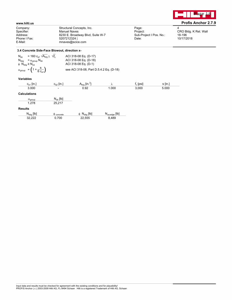
3.4 Concrete Side-Face Blowout, direction x-
Nsb = 160 ca1 √Abrg l √f'c ACI 318-08 Eq. (D-17)Nsbg = agroup Nsb ACI 318-08 Eq. (D-18)f Nsbg ≥ Nua ACI 318-08 Eq. (D-1)
agroup = (1 + s6 ca1) see ACI 318-08, Part D.5.4.2 Eq. (D-18)
Variables
ca1 [in.] ca2 [in.] Abrg [in.2] l f'c [psi] s [in.] 3.000 - 0.92 1.000 3,000 5.000
Calculations
agroup Nsb [lb] 1.278 25,217
Results
Nsbg [lb] f concrete f Nsbg [lb] Nua,edge [lb] 32,222 0.700 22,555 8,489
Page 18

www.hilti.us Profis Anchor 2.7.9
Input data and results must be checked for agreement with the existing conditions and for plausibility!PROFIS Anchor ( c ) 2003-2009 Hilti AG, FL-9494 Schaan Hilti is a registered Trademark of Hilti AG, Schaan
Company:Specifier:Address:Phone I Fax:E-Mail:
Structural Concepts, Inc.Manuel Naves8230 E. Broadway Blvd, Suite W-75207212324 | [email protected]
Page:Project:Sub-Project I Pos. No.:Date:
5CRO Bldg. K Ret. Wall18-19610/17/2018
4 Shear load Load Vua [lb] Capacity f f f f Vn [lb] Utilization bbbbV = Vua/f f f f Vn Status
Steel Strength* 234 12,971 2 OK
Steel failure (with lever arm)* N/A N/A N/A N/A
Pryout Strength** 936 17,200 6 OK
Concrete edge failure in direction x+** 936 8,428 12 OK
* anchor having the highest loading **anchor group (relevant anchors)
4.1 Steel Strength Vsa = Ase,V futa ACI 318-08 Eq. (D-19)f Vsteel ≥ Vua ACI 318-08 Eq. (D-2)
Variables
Ase,V [in.2] futa [psi] 0.31 65,000
Calculations
Vsa [lb] 19,955
Results
Vsa [lb] f steel f Vsa [lb] Vua [lb] 19,955 0.650 12,971 234
4.2 Pryout Strength
Vcpg = kcp [(ANcANc0
) y ec,N y ed,N y c,N y cp,N Nb] ACI 318-08 Eq. (D-31)
f Vcpg ≥ Vua ACI 318-08 Eq. (D-2)ANc see ACI 318-08, Part D.5.2.1, Fig. RD.5.2.1(b) ANc0 = 9 h2
ef ACI 318-08 Eq. (D-6)
y ec,N = ( 1
1 + 2 e'N
3 hef) ≤ 1.0 ACI 318-08 Eq. (D-9)
y ed,N = 0.7 + 0.3 ( ca,min1.5hef
) ≤ 1.0 ACI 318-08 Eq. (D-11)
y cp,N = MAX(ca,mincac
, 1.5hefcac
) ≤ 1.0 ACI 318-08 Eq. (D-13)
Nb = kc l √f'c h1.5ef ACI 318-08 Eq. (D-7)
Variables
kcp hef [in.] ec1,N [in.] ec2,N [in.] ca,min [in.] 2 10.000 0.000 0.000 3.000
y c,N cac [in.] kc l f'c [psi] 1.000 - 24 1 3,000
Calculations
ANc [in.2] ANc0 [in.2] y ec1,N y ec2,N y ed,N y cp,N Nb [lb] 350.00 900.00 1.000 1.000 0.760 1.000 41,569
Results
Vcpg [lb] f concrete f Vcpg [lb] Vua [lb] 24,572 0.700 17,200 936
Page 19

www.hilti.us Profis Anchor 2.7.9
Input data and results must be checked for agreement with the existing conditions and for plausibility!PROFIS Anchor ( c ) 2003-2009 Hilti AG, FL-9494 Schaan Hilti is a registered Trademark of Hilti AG, Schaan
Company:Specifier:Address:Phone I Fax:E-Mail:
Structural Concepts, Inc.Manuel Naves8230 E. Broadway Blvd, Suite W-75207212324 | [email protected]
Page:Project:Sub-Project I Pos. No.:Date:
6CRO Bldg. K Ret. Wall18-19610/17/2018
4.3 Concrete edge failure in direction x+
Vcbg = (AVcAVc0
) y ec,V y ed,V y c,V y h,V y parallel,V Vb ACI 318-08 Eq. (D-22)
f Vcbg ≥ Vua ACI 318-08 Eq. (D-2)AVc see ACI 318-08, Part D.6.2.1, Fig. RD.6.2.1(b) AVc0 = 4.5 c2
a1 ACI 318-08 Eq. (D-23)
y ec,V = ( 1
1 + 2e'v
3ca1) ≤ 1.0 ACI 318-08 Eq. (D-26)
y ed,V = 0.7 + 0.3( ca21.5ca1
) ≤ 1.0 ACI 318-08 Eq. (D-28)
y h,V = √1.5ca1ha
≥ 1.0 ACI 318-08 Eq. (D-29)
Vb = (8 ( leda)0.2
√da) l √f'c c1.5a1 ACI 318-08 Eq. (D-25)
Variables
ca1 [in.] ca2 [in.] ecV [in.] y c,V ha [in.] 7.000 - 0.000 1.000 48.000
le [in.] l da [in.] f'c [psi] y parallel,V 5.000 1.000 0.625 3,000 1.000
Calculations
AVc [in.2] AVc0 [in.2] y ec,V y ed,V y h,V Vb [lb] 273.00 220.50 1.000 1.000 1.000 9,724
Results
Vcbg [lb] f concrete f Vcbg [lb] Vua [lb] 12,040 0.700 8,428 936
5 Combined tension and shear loads bN bV z Utilization bN,V [%] Status
0.987 0.111 1.000 92 OK
bNV = (bN + bV) / 1.2 <= 1
6 Warnings• The anchor design methods in PROFIS Anchor require rigid anchor plates per current regulations (ETAG 001/Annex C, EOTA TR029, etc.). This
means load re-distribution on the anchors due to elastic deformations of the anchor plate are not considered - the anchor plate is assumed to be sufficiently stiff, in order not to be deformed when subjected to the design loading. PROFIS Anchor calculates the minimum required anchor plate thickness with FEM to limit the stress of the anchor plate based on the assumptions explained above. The proof if the rigid base plate assumption is valid is not carried out by PROFIS Anchor. Input data and results must be checked for agreement with the existing conditions and for plausibility!
• Condition A applies when supplementary reinforcement is used. The Φ factor is increased for non-steel Design Strengths except Pullout Strength and Pryout strength. Condition B applies when supplementary reinforcement is not used and for Pullout Strength and Pryout Strength. Refer to your local standard.
• Checking the transfer of loads into the base material and the shear resistance are required in accordance with ACI 318 or the relevant standard!
Fastening meets the design criteria!
Page 20

www.hilti.us Profis Anchor 2.7.9
Input data and results must be checked for agreement with the existing conditions and for plausibility!PROFIS Anchor ( c ) 2003-2009 Hilti AG, FL-9494 Schaan Hilti is a registered Trademark of Hilti AG, Schaan
Company:Specifier:Address:Phone I Fax:E-Mail:
Structural Concepts, Inc.Manuel Naves8230 E. Broadway Blvd, Suite W-75207212324 | [email protected]
Page:Project:Sub-Project I Pos. No.:Date:
7CRO Bldg. K Ret. Wall18-19610/17/2018
Coordinates Anchor in.
Anchor x y c-x c+x c-y c+y
1 -2.000 -2.500 3.000 7.000 - -
2 2.000 -2.500 7.000 3.000 - -3 -2.000 2.500 3.000 7.000 - -4 2.000 2.500 7.000 3.000 - -
7 Installation dataAnchor plate, steel: - Anchor type and diameter: AWS D1.1 GR. B 5/8
Profile: Rectangular HSS (AISC); 4.000 x 3.000 x 0.188 in. Installation torque: -Hole diameter in the fixture: df = 0.688 in. Hole diameter in the base material: - in.Plate thickness (input): 0.750 in. Hole depth in the base material: 10.000 in.Recommended plate thickness: not calculated Minimum thickness of the base material: 10.813 in.
R - user is responsible to ensure a rigid base plate for the entered thickness with appropriate
solutions (stiffeners,...)
1 2
3 4
2.000 4.000 2.000
1.50
05.
000
1.50
0x
y
4.000 4.000
4.00
04.
000
Page 21
www.hilti.us Profis Anchor 2.7.9
Input data and results must be checked for agreement with the existing conditions and for plausibility!PROFIS Anchor ( c ) 2003-2009 Hilti AG, FL-9494 Schaan Hilti is a registered Trademark of Hilti AG, Schaan
Company:Specifier:Address:Phone I Fax:E-Mail:
Structural Concepts, Inc.Manuel Naves8230 E. Broadway Blvd, Suite W-75207212324 | [email protected]
Page:Project:Sub-Project I Pos. No.:Date:
8CRO Bldg. K Ret. Wall18-19610/17/2018
8 Remarks; Your Cooperation Duties• Any and all information and data contained in the Software concern solely the use of Hilti products and are based on the principles, formulas and
security regulations in accordance with Hilti's technical directions and operating, mounting and assembly instructions, etc., that must be strictly complied with by the user. All figures contained therein are average figures, and therefore use-specific tests are to be conducted prior to using the relevant Hilti product. The results of the calculations carried out by means of the Software are based essentially on the data you put in. Therefore, you bear the sole responsibility for the absence of errors, the completeness and the relevance of the data to be put in by you. Moreover, you bear sole responsibility for having the results of the calculation checked and cleared by an expert, particularly with regard to compliance with applicable norms and permits, prior to using them for your specific facility. The Software serves only as an aid to interpret norms and permits without any guarantee as to the absence of errors, the correctness and the relevance of the results or suitability for a specific application.
• You must take all necessary and reasonable steps to prevent or limit damage caused by the Software. In particular, you must arrange for the regular backup of programs and data and, if applicable, carry out the updates of the Software offered by Hilti on a regular basis. If you do not use the AutoUpdate function of the Software, you must ensure that you are using the current and thus up-to-date version of the Software in each case by carrying out manual updates via the Hilti Website. Hilti will not be liable for consequences, such as the recovery of lost or damaged data or programs, arising from a culpable breach of duty by you.
Page 22