structural behaviour of beam with … behaviour of beam with recycled building materials wadhah m....
TRANSCRIPT

www.ijaemr.com Page 140
International Journal of Advanced Engineering and Management Research
Vol. 2 Issue 1, 2017
www.ijaemr.com ISSN: 2456-3676
STRUCTURAL BEHAVIOUR OF BEAM WITH RECYCLED BUILDING
MATERIALS
Wadhah M. Tawfeeq1, Noof Al-Shidi2, Sara Al-Saidi2, Karwan Al-Mamari2, Zuwaina Al-Mamari2,
Said Al-Zaabi2.
1Assistant Professor, Faculty of Engineering, Sohar University, Sohar, PC 311, Oman;
2Undergraduate student of Engineering, Sohar University, Sohar, PC 311, Oman
ABSTRACT
Concrete block, interlock, and tiles are waste that causes environmental pollution.
Approximately three quarters of volume of concrete mix is occupied by aggregate. The
utilization of material previously mentioned as a course aggregate in concrete would have a
positive effect on the economy and reduce environmental pollution. In this project, an
experimental investigation conducted to study the flexural behaviour of beam with recycled
building material as a coarse aggregate. General properties of aggregate were studied such as
specific gravity, water absorption, clay percentage and Abrasion. Ten beams casted with
different crushed building waste material replacement contents varying from 25%, 50%, and
100%. All the beams are simply supported and subjected to one concentrated loads at mid-span
of the beam. It has found that the plain cement concrete specimen has shown a typical crack
propagation pattern which leaded into splitting of beam. In cylinder the maximum tensile
splitting strength was found at 50% interlock about 3.32 N/mm2.Also the maximum stress in
cubes was found at 25% tiles about 38.67 N/mm2.And the maximum flexural stress for the
prisms was found at 50% concrete block and 100% interlock about 5.4 N/mm2. The load
carrying capacity were compared with theoretical values calculated using BS8110 (Design
Manual).
Key Words: Beam, Behavior, Compressive Strength, Physical Properties, Reinforced Concrete,
Recycled, Aggregate.
1. INTRODUCTION
Construction wastes recycling are creating some construction solution optimized for the
sustainability of safe disposal of residues and tapped into something useful. These techniques in
recycling of construction waste strong beams for the preservation of the environment and energy
sources. Can be studied flexural behavior by applied load and consequently can know the
possibility of using recycle aggregates cores (RAC) as building materials. Contribute to the
recycling of construction waste in cities in reducing the shortage of available spaces for
construction and can also use rotating waste in paving roads and some other construction

www.ijaemr.com Page 141
applications. Some statistics refer to high levels in construction waste recycling operations in
some countries such as Japan=98% and Netherlands =90%.[1] At the level of world consumption,
concrete factory produces 8 to 12 billion tons annually. Meaning that each person consumes one
tons of concrete every year .Due to urban development, it is expected to increase the rate of
consumption until 2020 to increase construction such as bridges, roads and tall buildings. In
India, the total amount of construction and building waste (11.4 to 14.69) million tons annually.
Construction waste was introduced after the Second World War because of war ruins of
buildings and roads. In the 1970 s the United States began to use packing material construction,
Foundations, and basic coarse material (back 1977).[2,3]
Today, we are running out of both reclamation sites and landfill space. With the current trend,
our landfills will be full in mid to late-2010s, and public fill capacity will be depleted in the near
future. In 2013, the mixed construction waste accounts for about 25% of the total waste intake at
the three existing landfills. If there are insufficient public fill capacity and waste reduction
measures being implemented, more public fill would probably be diverted to landfills and the
landfill life will be further shortened.[3,4] Wadhah M Tawfeeq et al, (2016)[5] investigated the
possible use of crushed pavement blocks as coarse aggregate for the production of new concrete.
The concrete specimens were prepared by 100% natural coarse aggregate; which would then be
replaced by crushed pavement blocks at various percentages (50 and 100%). The mechanical and
physical properties of crushed pavement block aggregates such as specific gravity, clay percent,
grading, water content and water absorption were tested. Experimental results indicated that
absorption of coarse crushed pavement blocks aggregate were about 221% higher than that of
natural aggregate. The compressive strength of 28 days by using crushed pavement blocks
aggregate showed an increment of nearly 8% when it fully replaced the natural aggregate in
concrete mixes. Wadhah M Tawfeeq et al, (2016)[6] conducted an experimental investigation to
study the flexural behavior of concrete beams with stone slurry as a fine aggregate. General
properties of aggregate were studied such as specific gravity, water absorption and water content.
Six beams casted with different stone slurry replacement contents varying from 0%-50% by. All
the beams were simply supported and subjected to one concentrated loads at mid-span of the
beam, by using 600kN flexural and transverse frame. It has found that the plain cement concrete
specimen has shown a typical crack propagation pattern which leaded into splitting of beam. But
due to replacement of 5% stone slurry, cracks gets ceased which result into ductile behavior. The
optimum percent of stone slurry to be used was found to be 5%. Also the compressive strength of
concrete cubes is increased slightly by the replacement of 5% stone slurry. The load carrying
capacity were com-pared with theoretical values calculated using BS8110 (Design Manual).
Wadhah M Tawfeeq et al, (2016)[7] studied the possible use of crushed Concrete Hollow Blocks
as coarse aggregate to produce a new concrete by using construction and demolition waste as
raw material to give positive effect on the economy. The compressive strength of concrete at 7 &
28 days of age of concrete mix have been determined using natural coarse aggregate. The
replacement of the coarse aggregate by crushed Concrete Hollow Blocks was at three different
percentages (0 %, 50 %, and 100 %). The mechanical and physical properties of aggregate were
investigated such as specific gravity, water absorption, water content, sieve analysis and clay
percent. Wadhah M Tawfeeq et al, (2016)[8] investigated the effects of using the crushed tiles

www.ijaemr.com Page 142
(CT) as a coarse aggregate in the concrete mix. The CT is an industrial waste material, and then
reuses it in the construction fields will reduce the concrete costs and reduce the environmental
pollution. The general properties, such as the specific gravity, water absorption and water content
of the natural crushed aggregate and the CT aggregate were tested and compared with natural
aggregate. Three different replacement percentages of CT aggregates (0%, 50% and 100%) were
used in the concrete mix, in each replacement percentage; W/C and G/S were changed as a
parametric study to investigate their effects on slump and compressive strength. In general, the
results confirm that increasing the W/C will cause to increase the workability and decrease the
compressive strength of the concrete mix that with CT aggregate. For example, the compressive
strength of concrete mix for 100% replacement of crushed tiles was 28 MPa with W/C=0.55 and
G/S=1.1, in comparison with control mix (0% of CT) was 38.8 MPa; showed 27.83% decreasing.
While the slump of fresh concrete showed 37.50% increasing.
In Oman a construction and demolition waste (CDW) is one of the heaviest and most
voluminous waste streams generated. It accounts for approximately 25% - 30% of all waste
generated in Oman and consists of numerous materials, including concrete, blocks, gypsum,
wood, glass, metals, plastic, solvents, asbestos and excavated soil, many of which can be
recycled. CDW arises from activities such as the construction of buildings and civil
infrastructure, total or partial demolition of buildings and civil infrastructure, road planning and
maintenance. [4] A big amount of waste produced from different sectors. There is around 735341
tons of construction and demolition wastes accounts until 2009. The reasons for that, is the
continuous increase in both the population and construction projects. According to the ministry
of housing there is a sequential increase in the construction projects around Oman from 2006 to
2010. [4] The problem statement of this study is working to develop strategies to reduce
environmental pollution and increase and preserve natural resources for future generations by
recycling and use of construction waste. While the objective are to do the experiment (specific
gravity, water absorption, clay percent and los angles abortion test) to find the properties of
replacement material. Also to investigate the effect of replacement percentage and material on
flexural behaviour, of beam.
2. METHODOLOGY
In this study, four types of coarse aggregates were used; natural crushed aggregates, crushed tiles
aggregates, crushed concrete blocks aggregates and Crushed Pavement Blocks (interlock)
Aggregates, and the cement quantity for all mixes was 400kg. The different replacement ratios
were used for coarse aggregate (25%, 50% & 100% replacement). The (gravel/sand) ratio was
used (1.1). The (cement/water) ratio was used (0.5). The water was adjusted to keep the slump
between 100-180 mm. Before mixing, the characterizations of aggregates such as the grading,
water absorption, water content, abrasion and clay percent tests were measured. The bench
marking trial mix was 400 : 835.2 : 904.8 / 0.5 for one meter cube of concrete. The expected 28
days compressive strength is more than 35 MPa and the workability (slump) between 100-180
mm.

www.ijaemr.com Page 143
3. EXPERIMENTAL MATERIALS
Natural sand from local crusher in Salan was used. The grading of the fine aggregate and the
limits of aggregate as the British specification BS 882: 1992 [9]. Crushed gravel of maximum
aggregate size 20 mm from Saa'a region was used, Waste tiles were brought from tiles Sohar
Tiles factory and crushed, the crushed blocks were brought from Al-Batinah International factory
in Sohar (AL-O'hi- Sultanate of Oman) and it was graded in the laboratory. The crushed
pavement blocks were collected from various sources such as waste of concrete pavement,
factories, expire concrete pavement from pavements and sidewalks and surplus material from
construction sites. The grading of this aggregate conforms to the British Specification BS
882:1992[9]. The cement used in this study is Fujairah cement industries O.P.C. according to
British Standard Specification BS EN 197-1:2000[10]. Potable water was used in concrete trial
mixes and in curing.
Table 1 : Material Properties
Test Name
Sp
ecif
ic
Gra
vit
y
Wate
r
Ab
sorp
tio
n
Los
An
gel
es
Ab
rasi
on
Natural Coarse
Aggregate(NA) 2.7% 1.62% 1.8%
Crushed Tiles
Aggregate(CTA) 2.435% 7.8% 21.7%
Crushed Concrete
Blocks
Aggregate(CCBA)
2.39% 1.98% 2.03%
Crushed Pavement
Block Aggregates
(CPBA)
2.54% 5.36% 4.01%
4. DESIGN OF SIMPLY SUPPORTED BEAM
According to BS8110-1997[11], the ultimate moment of resistance of singly-reinforced
rectangular beams can be determined in terms of concrete capacity and the steel capacity. The
maximum compressive force which can be resisted by the concrete corresponds to the maximum
depth permitted for the neutral axis. If the maximum neutral axis depth is limited to 0.5d the steel
stress will reach its design strength of 0.95fy. The maximum ultimate moment of resistance of a
singly-reinforced beam in which the dimensions b and d and the area of reinforcing steel As are
known is given by the lesser of the following equations:
Based on the concrete strength
Mult, concrete = 0.156bd 2fcu
Based on the steel strength where z = 0.775d
Mult, steel = 0.95fyAs z

www.ijaemr.com Page 144
In this study 10 mm bar diameter was used, the concrete cover is equal to 25mm, height of mold
(H)=200 mm and breadth (b) of the mould=100mm. as shown in Figures 1-3.
Figure 1 Beam Dimension
Figure 2 Beam Steel Reinforcement
Figure 3 Adopted Simply Supported Beam Details
5. CASTING OF SPECIMENS
The materials were weighed accurately using a digital weighing instrument. For plain concrete,
fine aggregates, coarse aggregate, cement, water were added to mixing machine and mixed
thoroughly. For preparing the specimen for compressive, tensile, and flexure strength permanent
steel moulds, cube, cylinder and prism respectively were used, while wood frame were used for
casting the reinforced concrete beams. Before mixing the concrete, the sides and the bottom of
the all the mould were properly oiled for easy demolding. Ten beams have been casted and with
each beam three cubes, three cylinders and one prism have been casted.
6. TEST RESULTS AND DISCUSSION
This paragraph describes the test result in this study. The concrete strength, test observation,
failure modes and deformed shape at failure were presented. The behaviour and performance
during the flexural beam test are also detailed in this paragraph.The discussion is based on
ultimate capacity, and concrete crushing strength. The design calculation of and ultimate load are

www.ijaemr.com Page 145
also conducted and discussed in compared to the experimental results. Pressing machine with
150 Ton capacity, load cell with 600kN Max capacity, and Electronic Dial gauge with 25.4mm
capacity where used. Figures 4-6 shows the concrete compressive strength, flexural strength and
tensile strength respectively.
Figure 4: Cube Compressive Strength for Each Designated Beam Composition
Figure 5: Prism Flexural Strength for Each Designated Beam Composition
Figure 6: Cylinder Tensile Strength for Each Designated Beam Composition
6.1 Beam B1 (Bench Mark)
This beam has 0% recycled aggregate, with dimension as all other test specimens and had
concrete cube strength at 37.5MPa. The specimen procedure testing was identical as detailed in
the test setup shown in Figure (7). By the starting of the loading, till the first crack was observed
the specimen behaved linearly. After that, the displacement increased significantly, and the width
of crakes increased until complete failure occurred. We can see that the cracks were observed
under the position of the load and expended through the beam depth and at the region were the
maximum bending moment concentrated. Figure (8) shows the failure mode prophesies at the
end of the test. The failure mode was mainly by flexural bending and reinforcement bars reach to
the maximum stress region at the position of the load were the maximum bending moment
concentrated. However, continuing loading combined flexural bending and concrete crushing
occurred. 94.757 kN was the maximum failure load measured in the test. The relation between
the load applied to the specimens and the displacement are shown in the Figure (9).

www.ijaemr.com Page 146
Figure 7: Beam B1Test Set-Up
Figure 8: Beam B1 after Failure
Figure 9: Beam B1 Relation between Load and Displacement
6.2 Beam B2 (25% crushed interlock)
This beam contain 25% of crushed interlock, with dimension as all other test specimens and had
concrete cube strength at 36.5 MPa. By the starting of the loading, till the first crack was
observed the specimen behaved linearly. After that, the displacement increased significantly, and
the width of crakes increased until complete failure occurred. We can see that the cracks were
observed under the position of the load and expended through the beam depth and at the region
were the maximum bending moment concentrated. The failure mode was mainly by flexural
bending and reinforcement bars reach to the maximum stress region at the position of the load
were the maximum bending moment concentrated. However, continuing loading combined
flexural bending and concrete crushing occurred. 94.757kN was the maximum failure load
measured in the test. The relation between the load applied to the specimens and the
displacement are shown in the Figure (10).
www.ijaemr.com Page 147
Figure 10: Beam B2 Relation between Load and Displacement
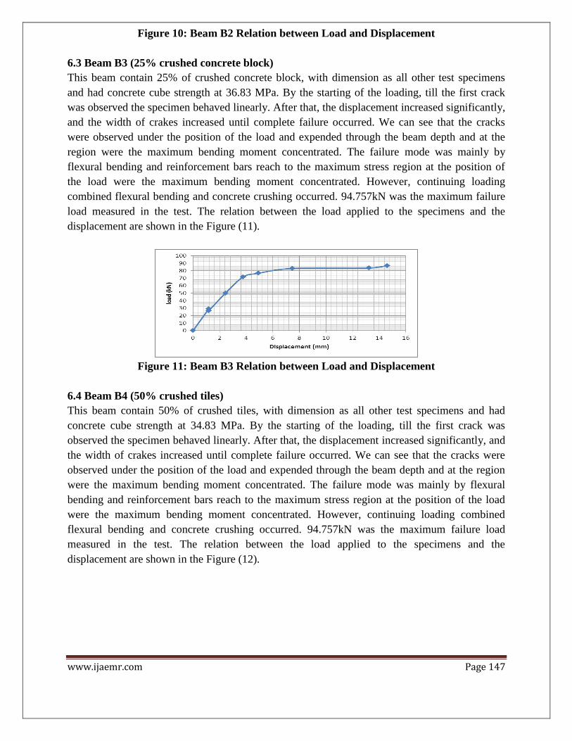
6.3 Beam B3 (25% crushed concrete block)
This beam contain 25% of crushed concrete block, with dimension as all other test specimens
and had concrete cube strength at 36.83 MPa. By the starting of the loading, till the first crack
was observed the specimen behaved linearly. After that, the displacement increased significantly,
and the width of crakes increased until complete failure occurred. We can see that the cracks
were observed under the position of the load and expended through the beam depth and at the
region were the maximum bending moment concentrated. The failure mode was mainly by
flexural bending and reinforcement bars reach to the maximum stress region at the position of
the load were the maximum bending moment concentrated. However, continuing loading
combined flexural bending and concrete crushing occurred. 94.757kN was the maximum failure
load measured in the test. The relation between the load applied to the specimens and the
displacement are shown in the Figure (11).
Figure 11: Beam B3 Relation between Load and Displacement
6.4 Beam B4 (50% crushed tiles)
This beam contain 50% of crushed tiles, with dimension as all other test specimens and had
concrete cube strength at 34.83 MPa. By the starting of the loading, till the first crack was
observed the specimen behaved linearly. After that, the displacement increased significantly, and
the width of crakes increased until complete failure occurred. We can see that the cracks were
observed under the position of the load and expended through the beam depth and at the region
were the maximum bending moment concentrated. The failure mode was mainly by flexural
bending and reinforcement bars reach to the maximum stress region at the position of the load
were the maximum bending moment concentrated. However, continuing loading combined
flexural bending and concrete crushing occurred. 94.757kN was the maximum failure load
measured in the test. The relation between the load applied to the specimens and the
displacement are shown in the Figure (12).

www.ijaemr.com Page 148
Figure 12: Beam B4 Relation between Load and Displacement
6.5 Beam B5 (25% crushed tiles)
This beam contains 25% of crushed tiles, with dimension as all other test specimens and had
concrete cube strength at 38.67MPa. By the starting of the loading, till the first crack was
observed the specimen behaved linearly. After that, the displacement increased significantly, and
the width of crakes increased until complete failure occurred. We can see that the cracks were
observed under the position of the load and expended through the beam depth and at the region
were the maximum bending moment concentrated. The failure mode was mainly by flexural
bending and reinforcement bars reach to the maximum stress region at the position of the load
were the maximum bending moment concentrated. However, continuing loading combined
flexural bending and concrete crushing occurred. 85.406kN was the maximum failure load
measured in the test. The relation between the load applied to the specimens and the
displacement are shown in the Figure (13).
Figure 13: Beam B5 Relation between Load and Displacement
6.6 Beam B6 (50% crushed concrete block)
This beam contain 50% of crushed concrete block, with dimension as all other test specimens
and had concrete cube strength at 30 MPa. By the starting of the loading, till the first crack was
observed the specimen behaved linearly. After that, the displacement increased significantly, and
the width of crakes increased until complete failure occurred. We can see that the cracks were
observed under the position of the load and expended through the beam depth and at the region
were the maximum bending moment concentrated. The failure mode was mainly by flexural
bending and reinforcement bars reach to the maximum stress region at the position of the load

www.ijaemr.com Page 149
were the maximum bending moment concentrated. However, continuing loading combined
flexural bending and concrete crushing occurred. 94.757kN was the maximum failure load
measured in the test. The relation between the load applied to the specimens and the
displacement are shown in the Figure (14).
Figure 14: Beam B6 Relation between Load and Displacement
6.7 Beam B7 (50% crushed interlock)
This beam contain 50% of crushed interlock, with dimension as all other test specimens and had
concrete cube strength at 36.167 MPa. By the starting of the loading, till the first crack was
observed the specimen behaved linearly. After that, the displacement increased significantly, and
the width of crakes increased until complete failure occurred. We can see that the cracks were
observed under the position of the load and expended through the beam depth and at the region
were the maximum bending moment concentrated. The failure mode was mainly by flexural
bending and reinforcement bars reach to the maximum stress region at the position of the load
were the maximum bending moment concentrated. However, continuing loading combined
flexural bending and concrete crushing occurred. 80.887 kN was the maximum failure load
measured in the test. The relation between the load applied to the specimens and the
displacement are shown in the Figure (15).
Figure 15: Beam B7 Relation between Load and Displacement
6.8 Beam B8 (100% crushed tiles)
This beam contain 100% of crushed tiles, with dimension as all other test specimens and had
concrete cube strength at 30.167 MPa. By the starting of the loading, till the first crack was
observed the specimen behaved linearly. After that, the displacement increased significantly, and
the width of crakes increased until complete failure occurred. We can see that the cracks were
www.ijaemr.com Page 150
observed under the position of the load and expended through the beam depth and at the region
were the maximum bending moment concentrated. The failure mode was mainly by flexural
bending and reinforcement bars reach to the maximum stress region at the position of the load
were the maximum bending moment concentrated. However, continuing loading combined
flexural bending and concrete crushing occurred 94.757kN was the maximum failure load
measured in the test. The relation between the load applied to the specimens and the
displacement are shown in the Figure (16).
Figure 16: Beam B8 Relation between Load and Displacement
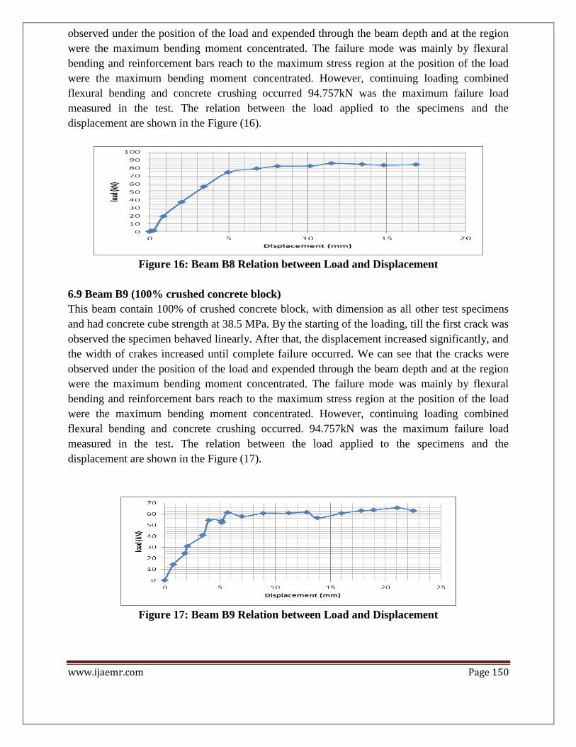
6.9 Beam B9 (100% crushed concrete block)
This beam contain 100% of crushed concrete block, with dimension as all other test specimens
and had concrete cube strength at 38.5 MPa. By the starting of the loading, till the first crack was
observed the specimen behaved linearly. After that, the displacement increased significantly, and
the width of crakes increased until complete failure occurred. We can see that the cracks were
observed under the position of the load and expended through the beam depth and at the region
were the maximum bending moment concentrated. The failure mode was mainly by flexural
bending and reinforcement bars reach to the maximum stress region at the position of the load
were the maximum bending moment concentrated. However, continuing loading combined
flexural bending and concrete crushing occurred. 94.757kN was the maximum failure load
measured in the test. The relation between the load applied to the specimens and the
displacement are shown in the Figure (17).
Figure 17: Beam B9 Relation between Load and Displacement

www.ijaemr.com Page 151
6.10 Beam B10 (100% crushed interlock)
This beam contain 100% of crushed interlock, with dimension as all other test specimens and had
concrete cube strength at 37.167 MPa. By the starting of the loading, till the first crack was
observed the specimen behaved linearly. After that, the displacement increased significantly, and
the width of crakes increased until complete failure occurred. We can see that the cracks were
observed under the position of the load and expended through the beam depth and at the region
were the maximum bending moment concentrated. The failure mode was mainly by flexural
bending and reinforcement bars reach to the maximum stress region at the position of the load
were the maximum bending moment concentrated. However, continuing loading combined
flexural bending and concrete crushing occurred. 94.757kN was the maximum failure load
measured in the test. The relation between the load applied to the specimens and the
displacement are shown in the Figure (18).
Figure 18: Beam B10 Relation between Load and Displacement
7. CONCLUSION
This study investigated experimentally the structural behavior of beam with recycled building
materials. Ten tests were conducted under one point loading bending. The raw materials were
tested to measure its properties. Hardened concrete tests were conducted to measure the
compressive, flexural and tensile strength of concrete.
1- The flexural strength for the beams is approximately different considerably by the recycled
materials.
2- The maximum value of compressive strength was found at 25% tiles about 38.67 N/mm2 and
the lowest value was at 50% concrete block about 30 N/mm2.
3- The maximum value of flexural strength was found at 50% concrete block and 100%
interlock about 5.4 N/mm2 and the lowest value was found at 50% interlock about 3.9
N/mm2.
4- The maximum value of tensile splitting strength was found at 50% interlock about 3.32
N/mm2 and the lowest value was found at 25% interlock about 2.29 N/mm2.
5- For all the beams the experimental maximum load of failure was 94.757 kN because the
failure happened in steel reinforcement.

www.ijaemr.com Page 152
REFERENCES
1- Construction & Demolition Waste. (2016, 8 Jun). Retrieved from
http://www.epd.gov.hk/epd/misc/cdm/introduction.htm.
2- http://www.eschooltoday.com/waste-recycling/what-is-composting.html
3- Joubert, M. (2013). National Strategy for Waste Mangement. “ Oman Observer “. Retrieved
from http://omanobserver.om/category/environment/
(4th November, 2013).
4- Al-kindi,A.H. (2010). Oman Waste Mangement Sector Workshop. By Oman Environment
Services Holding company, 5th February 2010.
5- Wadhah M. Tawfeeq, Othman AlShareedah, and Taimoor Hossain,'' Properties of Concrete
Mix with Crushed Pavement Blocks as Coarse Aggregate '', International Journal Of
Scientific& Engineering Research, Volume 7, Issue 7, July-(2016).
6- Wadhah M. Tawfeeq, Asma Almaqbali, Ashwaq Alkhawaldi, Hanan Almaqbali, and Amani
Alessai,'' Structural Performance Of Reinforced Concrete Beam With Omani Recycled Stone
Slurry '', International Journal of Advance Research, Volume 4, Issue 7, July (2016).
7- Wadhah M. Tawfeeq, Ahmed Al-Shibli, Mohammed Al-Jarwani and Othman Al-Zakwani,
“Slump and Compressive Strength of Concrete Mix with Crushed Concrete Blocks as Coarse
Aggregate” International Journal of Advanced Engineering and Management Research Vol. 1
Issue 7 September (2016).
8- Wadhah M. Tawfeeq, Maryam AlSaidi, Abdullah Al-Kamzari, Mohammed Al-Shibli, and
Zainab Al-Mamari, “Using Crushed Tiles as Coarse Aggregate in Concrete Mix” 3rd
International Conference on Civil, Environment and Waste Management (CEWM-16) Sept.
12-14, 2016 Dubai (UAE).
9- BS882:1992,"Aggregates from Natural Sources for Concrete"1992.
10- BS EN 197-1:2000. (2000). Cement. Composition, specifications and conformity criteria
for common cements. British Standard.
11- BS 8110-1997 "Structural use of concrete. Code of practice for design and construction"