structural behavior of fiber reinforced steel concrete ... · structural behavior . o. f...
TRANSCRIPT
Structural Behavior of Fiber-Reinforced Steel-Concrete Composite Elements under Hazard Loads
Faezeh Faghih1), Dipankar Das2), Samer Gendy3) and *Ashraf Ayoub4)
1), 2), 3), 4) School of Mathematics, Computer Science & Engineering, City University
London, Northampton Square, London, U.K. 1) [email protected] 2) [email protected] 3) [email protected]
Abstract. The addition of Steel Fibers (SF) to concrete has been widely studied in the past decades as a mean to control its crack behaviour and maintain its ductility in tension. It has been verified that the use of these fibers at an appropriate dosage can change the behaviour of structural members from brittle to ductile. Further, since the discovery of carbon nanotubes/fibers (CNT/CNF), they have been also considered as efficient fibers to be used in construction materials such as concrete. Previous experimental work has shown that incorporation of CNF in cementitious composites can enhance the mechanical behaviour of material by reducing the size of macro- and micro-cracks resulting in higher strength and ductility. In addition, due to tunnel conductivity effect, CNF concrete exhibits properties necessary for self-sensing and self-health monitoring ability. This study aims to expand upon the use of SF and CNF concrete in structural members focusing on Steel-Concrete (SC) double skin composite systems. SC systems are quickly gaining popularity in the nuclear power industry worldwide mainly because of their many advantages such as modular and accelerated construction, cost effectiveness, good strength properties for given size members, in addition to excellent seismic and blast resistance. The use of both SF and CNF fiber reinforced concrete in SC systems could potentially be advantageous in many aspects such as performance enhancement of the structure under normal loading conditions as well as in case of hazard loads. The research includes experimental tests and analytical studies to evaluate the performance of fiber-reinforced SC elements. The numerical work aims to develop a new finite element model to simulate the structural behaviour of SC members using fiber beam element formulations, in particular under the effect of natural and man-made hazards such as earthquake and impact loads. The study confirmed the benefits gained using the enhanced SC systems. Keywords: fibers; carbon nano-fibers; carbon nanotubes; SC panels; steel-concrete element
1)
Ph.D. 4)
Professor
1. Introduction
Concrete is a well-known construction material that has high compressive strength and low tensile strength. The behaviour of this material has been studied for better properties and many new forms of this material has been developed and introduced to the industry namely Lightweight concrete, fiber reinforced concrete, Ultra-high performance concrete, Reactive powder concrete. The most common and well researched material is fibre reinforced concrete using different fibers. The concept of using fibers is to enhance the tensile behaviour of the concrete by bridging the cracks and improving the load carrying capacity of the structural members. Concrete properties exist in multiple length scales of nano, micro and macro sizes and the properties of each scale is derived from those of the next smaller scale.
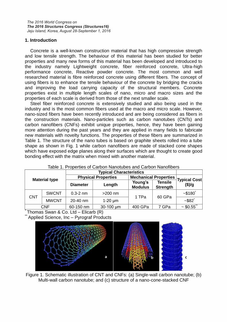
Steel fiber reinforced concrete is extensively studied and also being used in the industry and is the most common fibers used at the macro and micro scale. However, nano-sized fibers have been recently introduced and are being considered as fibers in the construction materials. Nano-particles such as carbon nanotubes (CNTs) and carbon nanofibers (CNFs) exhibit unique properties, hence, they have been gaining more attention during the past years and they are applied in many fields to fabricate new materials with novelty functions. The properties of these fibers are summarized in Table 1. The structure of the nano tubes is based on graphite sheets rolled into a tube shape as shown in Fig. 1 while carbon nanofibers are made of stacked cone shapes which have exposed edge planes along their surfaces which are thought to create good bonding effect with the matrix when mixed with another material.
Table 1. Properties of Carbon Nanotubes and Carbon Nanofibers
Material type
Typical Characteristics
Physical Properties Mechanical Properties Typical Cost
($)/g Diameter Length Young’s Modulus
Tensile Strength
CNT SWCNT 0.3-2 nm >200 nm
1 TPa 60 GPa ~$180*
MWCNT 20-40 nm 1-20 μm ~$82*
CNF 60-150 nm 30-100 μm 400 GPa 7 GPa ~ $0.55** * Thomas Swan & Co. Ltd – Elicarb (R)
** Applied Science, Inc – Pyrograf Products
Figure 1. Schematic illustration of CNT and CNFs: (a) Single-wall carbon nanotube; (b) Multi-wall carbon nanotube; and (c) structure of a nano-cone-stacked CNF
a b c
To date, the research on nano fibers have mainly been focused on the cement paste and it is concluded that the properties of the cement paste can be enhanced when using nano fibers by increased compressive strength, lower thermal conductivity, increased durability, and increased electrical conductivity for health monitoring purposes (Yazdanbakhsh and Grasley, 2011).
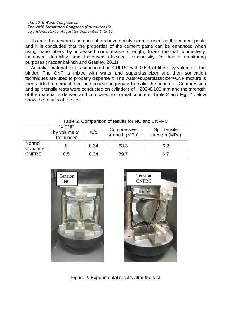
An initial material test is conducted on CNFRC with 0.5% of fibers by volume of the binder. The CNF is mixed with water and superplasticizer and then sonication techniques are used to properly disperse it. The water+superplasticizer+CNF mixture is then added to cement, fine and coarse aggregate to make the concrete. Compression and split tensile tests were conducted on cylinders of H200×D100 mm and the strength of the material is derived and compared to normal concrete. Table 2 and Fig. 2 below show the results of the test.
Table 2. Comparison of results for NC and CNFRC
% CNF by volume of
the binder w/c
Compressive strength (MPa)
Split tensile strength (MPa)
Normal Concrete
0 0.34 63.3 6.2
CNFRC 0.5 0.34 89.7 6.7
Figure 2. Experimental results after the test
Tension
NC
Tension
CNFRC
(0.5%)

Also, a comparison of the results for compression test is shown in Fig. 3.
Figure 3. Cylinder Compression Test Results
The results of this simple comparison show that concrete with similar proportions and constituents has higher strength under compression by 40% with higher strain capacity and the split tensile strength is increased by 8%. Further tests are being conducted to evaluate the ductility enhancement of the concrete by using such fibers in the concrete.
For this research study the type of structural member to be investigated is known as Steel Concrete sandwich wall, which is used for heavy structures. Steel Concrete composite (SC) construction is a sandwich system in which two steel plates encase the concrete in the middle. The composite action is provided by the shear studs. The SC system was originally devised for use in submerged tube tunnels over 25 years ago and it is used for high rise building core wall, power plants and offshore structures. SC enables the building to maintain a highly seismic condition. Fig. 4 shows the composition of this sandwich system.
Figure 4. SC system (Wright and Oduyemi, 1991)
0
10
20
30
40
50
60
70
80
90
100
0 0.0005 0.001 0.0015 0.002 0.0025 0.003
Str
ess
(MP
a)
Strain
NC
CNFRC-0.5%
2. Finite Element Model
Mullapudi and Ayoub (2010) developed a forced based fiber beam-column element considering softened membrane model, SMM (Zhu, 2000) where shear deformation is modelled using Timoshenko beam type approach along the element with the assumption of plane sections remain plane after deformations. The hysteretic steel material constitutive law follows the well-known Menegotto–Pinto model which includes isotropic strain hardening and Bauschinger effect. The concrete model describes the cyclic uni-axial constitutive relationships of cracked concrete in compression and tension. The envelop curve of the concrete in compression follows well-known modified Kent and Park model which offers a good balance between simplicity and accuracy. The effect of tension stiffening is considered by the model developed by Belarbi and Hsu (1995). The monotonic stress strain curve envelop of the concrete is represented by a parabolic curve, while the cyclic behaviour as described in detail by Yassin (1994).
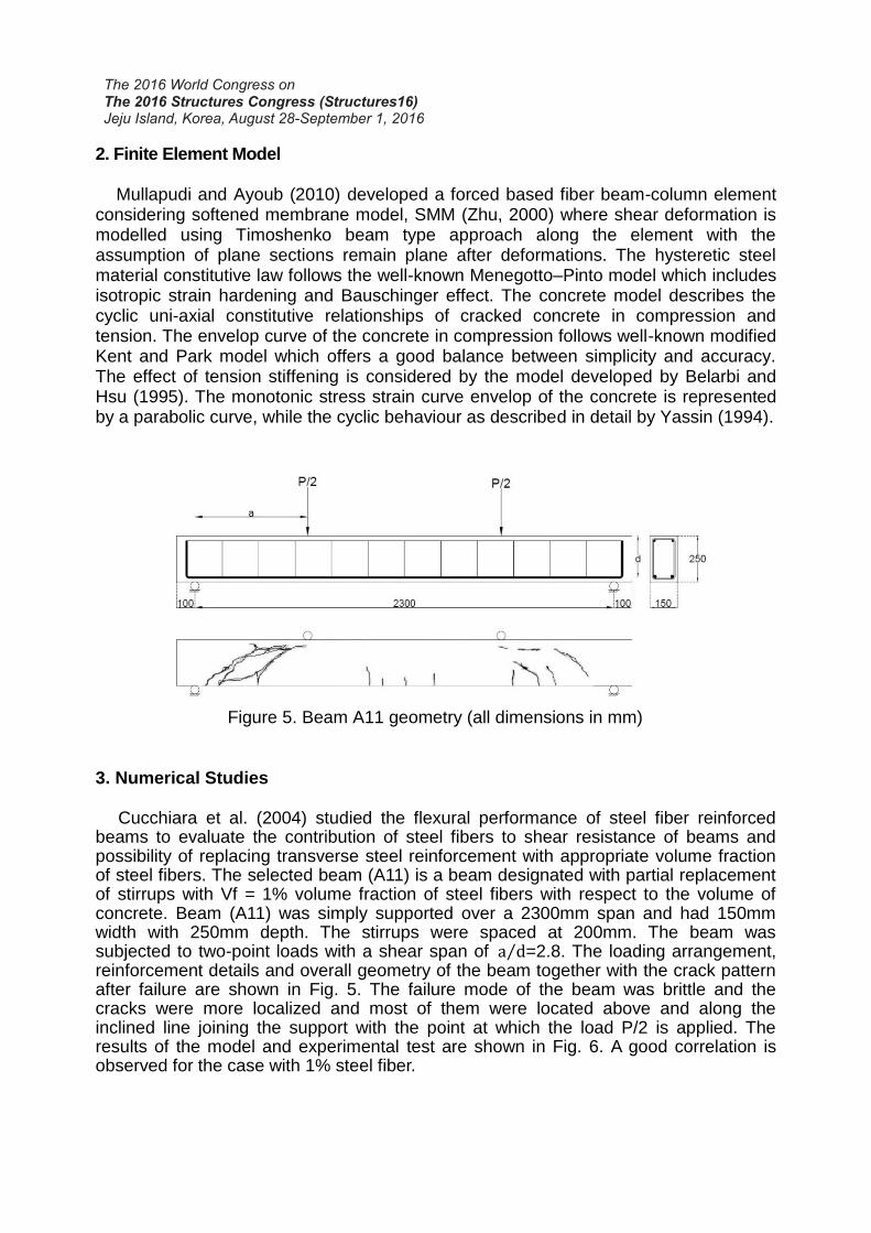
Figure 5. Beam A11 geometry (all dimensions in mm)
3. Numerical Studies
Cucchiara et al. (2004) studied the flexural performance of steel fiber reinforced beams to evaluate the contribution of steel fibers to shear resistance of beams and possibility of replacing transverse steel reinforcement with appropriate volume fraction of steel fibers. The selected beam (A11) is a beam designated with partial replacement of stirrups with Vf = 1% volume fraction of steel fibers with respect to the volume of concrete. Beam (A11) was simply supported over a 2300mm span and had 150mm width with 250mm depth. The stirrups were spaced at 200mm. The beam was subjected to two-point loads with a shear span of a d⁄ =2.8. The loading arrangement, reinforcement details and overall geometry of the beam together with the crack pattern after failure are shown in Fig. 5. The failure mode of the beam was brittle and the cracks were more localized and most of them were located above and along the inclined line joining the support with the point at which the load P/2 is applied. The results of the model and experimental test are shown in Fig. 6. A good correlation is observed for the case with 1% steel fiber.

Figure 6. Load – Deflection Curves (A11)
The effect of carbon nanofiber reinforced concrete with 1% of fibers was studied on the cyclic behaviour of the short shear-critical column by Howser (2010). The column was 20 (inch) in height with a 12 (inch) square cross‐section. The reinforcement contained six #8 longitudinal rebars and #2 stirrups with a spacing of 4.75 (inch) providing transverse reinforcement (See Fig. 7). The column was rigidly connected to a concrete foundation. An axial load equal to one tenth of the column’s axial capacity (87.4 kips) was applied followed by a lateral reversed cyclic load at the top of the column until failure occurred. The results of the behaviour of the column with reinforced concrete (RC), Steel fiber reinforced concrete (SCSFRC) and CNF concrete (CNFSCRC) is shown in Fig. 7.
Figure 7. Right: cross section of column (all dimensions in inches), Left: load-deflection behaviour of columns (Howser, 2010)
The column was modelled using the fiber beam element with the cross section of the element divided into 12 longitudinal fibers, and the load was applied to obtain the backbone curve of the cyclic behaviour. The result of the FE analysis and monotonic behaviour of the specimen is presented in Fig. 8.
0
50
100
150
200
250
0 5 10 15 20 25
Lo
ad (
kN
)
Deflection (mm)
Experiment-A11
FEAPpv-A11
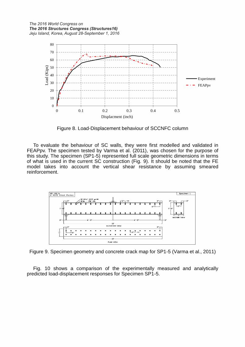
Figure 8. Load-Displacement behaviour of SCCNFC column
To evaluate the behaviour of SC walls, they were first modelled and validated in FEAPpv. The specimen tested by Varma et al. (2011), was chosen for the purpose of this study. The specimen (SP1-5) represented full scale geometric dimensions in terms of what is used in the current SC construction (Fig. 9). It should be noted that the FE model takes into account the vertical shear resistance by assuming smeared reinforcement.
Figure 9. Specimen geometry and concrete crack map for SP1-5 (Varma et al., 2011)
Fig. 10 shows a comparison of the experimentally measured and analytically predicted load-displacement responses for Specimen SP1-5.
0
10
20
30
40
50
60
70
80
0 0.1 0.2 0.3 0.4 0.5
Lo
ad (
Kip
s)
Displacment (inch)
Experiment
FEAPpv
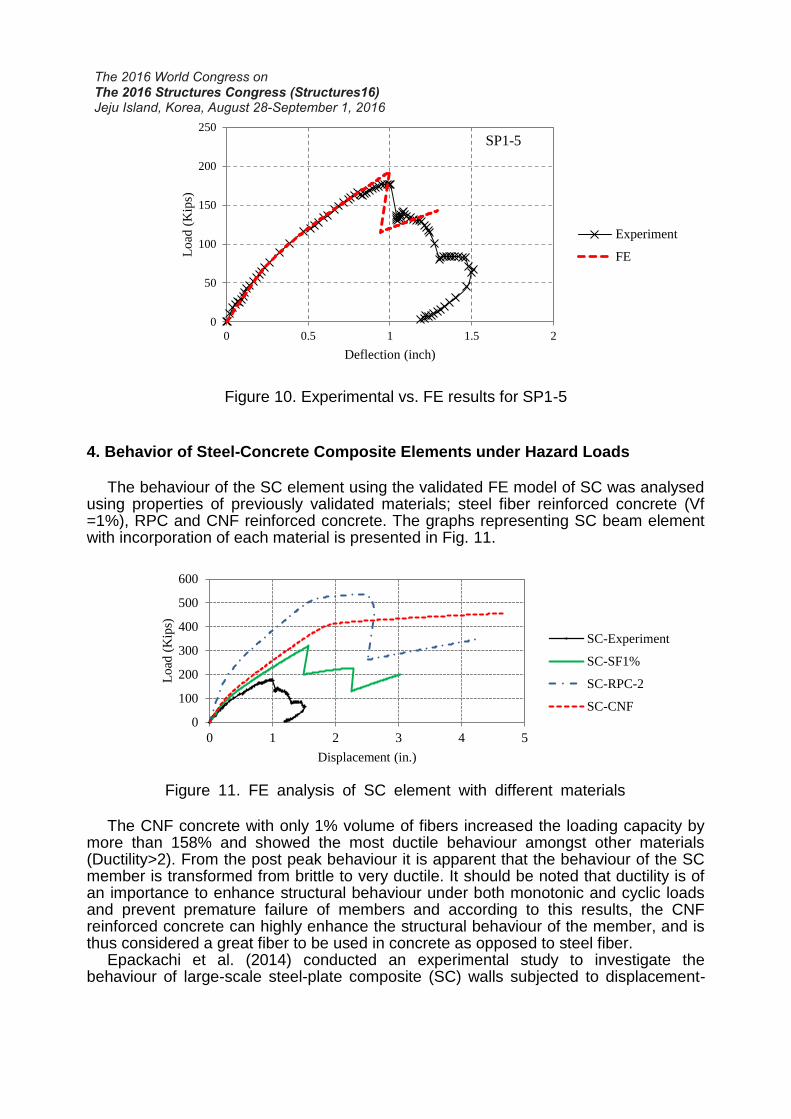
Figure 10. Experimental vs. FE results for SP1-5 4. Behavior of Steel-Concrete Composite Elements under Hazard Loads
The behaviour of the SC element using the validated FE model of SC was analysed using properties of previously validated materials; steel fiber reinforced concrete (Vf =1%), RPC and CNF reinforced concrete. The graphs representing SC beam element with incorporation of each material is presented in Fig. 11.
Figure 11. FE analysis of SC element with different materials
The CNF concrete with only 1% volume of fibers increased the loading capacity by more than 158% and showed the most ductile behaviour amongst other materials (Ductility>2). From the post peak behaviour it is apparent that the behaviour of the SC member is transformed from brittle to very ductile. It should be noted that ductility is of an importance to enhance structural behaviour under both monotonic and cyclic loads and prevent premature failure of members and according to this results, the CNF reinforced concrete can highly enhance the structural behaviour of the member, and is thus considered a great fiber to be used in concrete as opposed to steel fiber.
Epackachi et al. (2014) conducted an experimental study to investigate the behaviour of large-scale steel-plate composite (SC) walls subjected to displacement-
0
50
100
150
200
250
0 0.5 1 1.5 2
Lo
ad (
Kip
s)
Deflection (inch)
SP1-5
Experiment
FE
0
100
200
300
400
500
600
0 1 2 3 4 5
Lo
ad (
Kip
s)
Displacement (in.)
SC-Experiment
SC-SF1%
SC-RPC-2
SC-CNF
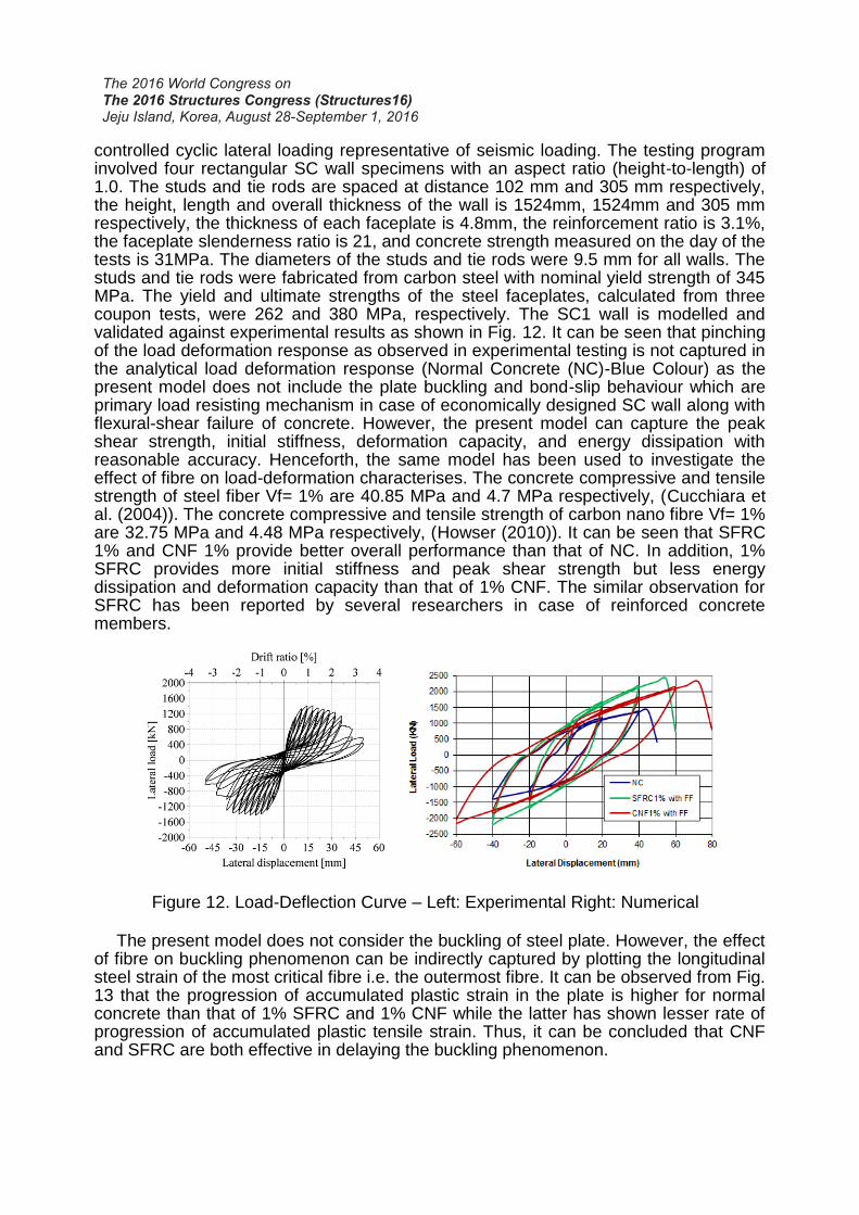
controlled cyclic lateral loading representative of seismic loading. The testing program involved four rectangular SC wall specimens with an aspect ratio (height-to-length) of 1.0. The studs and tie rods are spaced at distance 102 mm and 305 mm respectively, the height, length and overall thickness of the wall is 1524mm, 1524mm and 305 mm respectively, the thickness of each faceplate is 4.8mm, the reinforcement ratio is 3.1%, the faceplate slenderness ratio is 21, and concrete strength measured on the day of the tests is 31MPa. The diameters of the studs and tie rods were 9.5 mm for all walls. The studs and tie rods were fabricated from carbon steel with nominal yield strength of 345 MPa. The yield and ultimate strengths of the steel faceplates, calculated from three coupon tests, were 262 and 380 MPa, respectively. The SC1 wall is modelled and validated against experimental results as shown in Fig. 12. It can be seen that pinching of the load deformation response as observed in experimental testing is not captured in the analytical load deformation response (Normal Concrete (NC)-Blue Colour) as the present model does not include the plate buckling and bond-slip behaviour which are primary load resisting mechanism in case of economically designed SC wall along with flexural-shear failure of concrete. However, the present model can capture the peak shear strength, initial stiffness, deformation capacity, and energy dissipation with reasonable accuracy. Henceforth, the same model has been used to investigate the effect of fibre on load-deformation characterises. The concrete compressive and tensile strength of steel fiber Vf= 1% are 40.85 MPa and 4.7 MPa respectively, (Cucchiara et al. (2004)). The concrete compressive and tensile strength of carbon nano fibre Vf= 1% are 32.75 MPa and 4.48 MPa respectively, (Howser (2010)). It can be seen that SFRC 1% and CNF 1% provide better overall performance than that of NC. In addition, 1% SFRC provides more initial stiffness and peak shear strength but less energy dissipation and deformation capacity than that of 1% CNF. The similar observation for SFRC has been reported by several researchers in case of reinforced concrete members.
Figure 12. Load-Deflection Curve – Left: Experimental Right: Numerical
The present model does not consider the buckling of steel plate. However, the effect of fibre on buckling phenomenon can be indirectly captured by plotting the longitudinal steel strain of the most critical fibre i.e. the outermost fibre. It can be observed from Fig. 13 that the progression of accumulated plastic strain in the plate is higher for normal concrete than that of 1% SFRC and 1% CNF while the latter has shown lesser rate of progression of accumulated plastic tensile strain. Thus, it can be concluded that CNF and SFRC are both effective in delaying the buckling phenomenon.
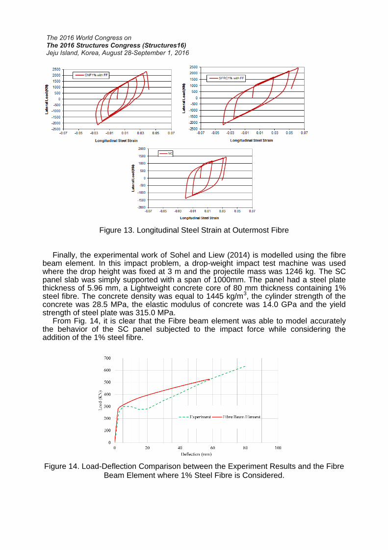
Figure 13. Longitudinal Steel Strain at Outermost Fibre Finally, the experimental work of Sohel and Liew (2014) is modelled using the fibre
beam element. In this impact problem, a drop-weight impact test machine was used where the drop height was fixed at 3 m and the projectile mass was 1246 kg. The SC panel slab was simply supported with a span of 1000mm. The panel had a steel plate thickness of 5.96 mm, a Lightweight concrete core of 80 mm thickness containing 1% steel fibre. The concrete density was equal to 1445 kg/m3, the cylinder strength of the concrete was 28.5 MPa, the elastic modulus of concrete was 14.0 GPa and the yield strength of steel plate was 315.0 MPa.
From Fig. 14, it is clear that the Fibre beam element was able to model accurately the behavior of the SC panel subjected to the impact force while considering the addition of the 1% steel fibre.
Figure 14. Load-Deflection Comparison between the Experiment Results and the Fibre Beam Element where 1% Steel Fibre is Considered.
5. Conclusions
Amongst the different developed concrete materials, steel fiber is the one mostly studied by researchers. Amongst newly discovered fibers the CNF has gained more attention in the world of nanotechnology and it is being studied extensively for the past few years. However, the study on CNF concrete is limited to the material level and is mainly focused on cement mortar paste. A material test on CNF mortar has shown that the addition of such fibers increases the compressive and flexural strength of the mortar. In this study, CNF is considered in the concrete and it was evident that the addition of 0.5% fibers improved the mechanical properties of the concrete. There is a gap in finding the effect of CNF concrete at the structural level, which in this study was analysed using the general purpose Finite Element Programme FEAPpv. The results showed that CNF concrete enhances the cyclic behaviour of the structural members as well as the strength, ductility and energy absorption of the member under load. Locally also they are effective in resisting/delaying buckling of the faceplate. The performance of SC walls proved to be better when CNF concrete is used compared to steel fiber reinforced concrete. References Belarbi A, Hsu TTC. (1995) “Constitutive Laws of Concrete in Tension and Reinforcing
Bars Stiffened by Concrete”, ACI Structural Journal, 91, 465–74. Cucchiara C., Mendola, L.L., and Papia, M. (2004) “Effectiveness of Stirrups and Steel
Fibers as Shear Reinforcement,” Cement and Concrete Composites, 26, pp. 777-786. Epackachi, Siamak., Nam H. Nguyen, Efe G. Kurt, Andrew S. Whittaker, Amit H. Varma
(2014) “In-Plane Seismic Behaviour of Rectangular Steel-Plate Composite Wall Piers”, American Society of Civil Engineers, DOI: 10.1061(ASCE) ST.1943-541X.0001148.
Howser, R. (2010), “Behavior of Steel Fibers and Carbon Nanofibers in Shear-Critical Reinforced Concrete Columns”, MS Thesis, Department of Civil engineering, University of Houston, State of Texas.
Mullapudi, T.R., Ayoub, A. (2010) “Modelling of the Seismic Behavior of Shear-Critical Reinforced Concrete Columns”, Engineering Structures, 32, pp.3601-3615.
Sohel, K. and Liew, J. (2014), “Behaviour of Steel–Concrete–Steel Sandwich Slabs Subject to Impact Load”, Journal of Constructional Steel Research, 100, pp.163-175.
Varma, A. H., Malushte, S. R., Sener, K. C., Boot, P. N., and Coogler, K. (2011) “Steel-Plate Composite (SC) Walls: Analysis and Design Including Thermal Effects” Transactions, SMiRT 21, New Delhi, India, 6-11 November, Paper No. 761.
Wright, H.D., Oduyemi, T.O.S., Evans, H.R., (1991) “The Experimental Behaviour of Double Skin Composite Elements”, J. Construct. Steel Research, 19, 97-110.
Yassin MHM. (1994) “Nonlinear Analysis of Prestressed Concrete Structures under Monotonic and Cyclic Loads”, Ph.D. Dissertation, Berkeley: University of California.
Yazdanbakhsh, A., Grasley, Z., Tyson, B., and Abu Al-Rub, R. A., (2010a) “Distribution of Carbon Nanofibers and Nanotubes in Cementitious Composites.” Journal of the Transportation Research Board, Transportation Research Board of the National Academies, Washington, 2142, 89–95.
Zhu, R. H., (2000) “Softened Membrane Model for Cracked Reinforced Concrete Considering Poisson Effect”, Ph.D. Dissertation, Dept. of Civil and Environmental Engineering, University of Houston, Houston, TX.