structural behavior of civil engineering structures...
TRANSCRIPT
STRUCTURAL BEHAVIOR OF CIVIL ENGINEERING STRUCTURES: HIGHLIGHT IN HISTORICAL AND MASONRY STRUCTURES
Paulo B. Lourenço 1 1 Associate Professor, University of Minho, Department of Civil Engineering, P-4800-058 Guimaraes, Portugal.
E-mail: [email protected]; Phone: +351 253 510200; Fax: +351 253 510217
Abstract Construction history is full of examples of lack of success. The importance of ancient constructions has been for long exclusively associated with the use of the building, meaning that successive changes were made to the building in order to fulfill its new function. Presently, modern societies understand built cultural heritage as a landmark of culture and diversity, which should last forever, being the task of the current generation to deliver the heritage in good shape for the generations to come. This act of culture poses high demands to engineers because deterioration is intrinsic to life (as an example the expected life of a modern building is fifty years).
European countries have developed throughout the years a valuable experience and knowledge in the field of conservation and restoration. In recent years, large investments have been concentrated in this field, leading to impressive developments in the areas of inspection, non-destructive testing, monitoring and structural analysis of historical constructions. These developments, and the recent guidelines for future reuse and conservation projects, allow for safer, economical and more adequate remedial measures. These issues and emblematic applications in case studies are addressed in the present paper. Keywords: experimental testing; structural analysis; ICOMOS recommendations; case studies. Introduction The analysis of historical masonry constructions is a complex task that requires specific training. The continuous changes in materials and construction techniques, that swiftly moved away from traditional practice, and the challenging technical and scientifical developments, which make new possibilities available for all the agents involved in the preservation of the architectural heritage, are key aspects in the division between the science of construction and the art of conservation and restoration.
The consideration of these aspects is complex and calls for qualified analysts that combine advanced knowledge in the area and engineering reasoning, as well as a careful, humble and, usually, time-consuming approach. Several methods and computational tools are available for the assessment of the mechanical behavior of historical constructions. The methods resort to different theories or approaches, resulting in: different levels of complexity (from simple graphical methods and hand calculations to complex mathematical formulations and large systems of non-linear equations), different availability for the practitioner (from readily available in any consulting engineer office to scarcely available in a few research oriented institutions and large consulting offices), different time requirements (from a few seconds of computer time to a few days of processing) and, of course, different costs.
The possibilities of structural analysis of historical constructions have been addressed in detail1, where it is advocated that most techniques of analysis are adequate, possibly for different applications, if combined with proper engineering reasoning. It is noted that only very recently the scientific community began to show interest in modern advanced testing (under displacement control) and advanced tools of analysis for historical constructions. The lack of experience in this field is notorious in comparison with more advanced research fields like concrete, soil, rock or composite mechanics.
Recently, Recommendations for the Analysis, Conservation and Structural Restoration of Architectural Heritage have been approved2. These Recommendations are intended to be useful to all those involved in conservation and restoration problems and not exclusively to the wide community of engineers. A key message, probably subliminal, is that those involved in historic preservation must recognize the contribution of the engineer. Often engineering advice seems to be regarded as something to be sought at the end of a project when all the decisions have been made, while it is clear that better solutions might have been available with an earlier engineering contribution.
An issue related with this message is that conservation engineering requires a different approach and different skills from those employed in designing new construction. Often historic fabric has been mutilated or destroyed by engineers who do not recognize this fact, with the approval of the authorities and other experts involved. Moreover, even when conservation skills are employed, there are frequent attempts by regulating authorities and engineers to make historic structures conform to modern design codes. This is generally unacceptable because the codes were written with quite different forms of construction in mind, because it is unnecessary and because it can be very destructive of historic fabric.
The need to recognize the distinction between modern design and conservation is also of relevance in the context of engineers’ fees. The usual fee calculation based on a percentage of the cost of the work specified is clearly inimical to best conservation practice, when the ideal is to avoid any structural intervention if possible. Being able to recommend taking no action might actually involve more investigative work and hence more cost to the engineer than recommending some major intervention.
Modern intervention procedures require a thorough survey of the structure and an understanding of its history. Any heritage structure is the result of the original design and construction, any deliberate changes that have been made and the ravages of time and chance. An engineer working on historical buildings must be aware that much of the effort in understanding their present state requires an attempt to understand the historical process. The engineer involved at the beginning of the process might not only have questions that can easily

be answered by the archaeologist or architectural historian, but he might be also able to offer explanations for the data being uncovered. ICOMOS Recommendations
The International Scientific Committee for the Analysis and Restoration of Structures of Architectural Heritage (ISCARSAH) has prepared recommendations2, intended to be useful to all those involved in conservation and restoration problems. These recommendations contain Principles, where the basic concepts of conservation are presented, and Guidelines, where the rules and methodology that a designer should follow are discussed. More comprehensive information on techniques and specific knowledge can be found elsewhere. In addition, normative and pre-normative are gradually becoming available, at least with respect to seismic rehabilitation, which is a major concern. Principles
A multi-disciplinary approach is obviously required in any restoration project and the peculiarity of heritage structures, with their complex history, requires the organization of studies and analysis in steps that are similar to those used in medicine. Anamnesis, diagnosis, therapy and controls, corresponding respectively to the condition survey, identification of the causes of damage and decay, choice of the remedial measures and control of the efficiency of the interventions. Thus, no action should be undertaken without ascertaining the likely benefit and harm to the architectural heritage.
A full understanding of the structural behavior and material characteristics is essential for any project related to architectural heritage. Diagnosis is based on historical information and qualitative and quantitative approaches. The qualitative approach is based on direct observation of the structural damage and material decay as well as historical and archaeological research, while the quantitative approach requires material and structural tests, monitoring and structural analysis. Often the application of the same safety levels used in the design of new buildings requires excessive, if not impossible, measures. In these cases other methods, appropriately justified, may allow different approaches to safety.
Therapy should address root causes rather than symptoms. Each intervention should be in proportion to the safety objectives, keeping intervention to the minimum necessary to guarantee safety and durability and with the least damage to heritage values. The choice between “traditional” and “innovative” techniques should be determined on a case-by-case basis with preference given to those that are least invasive and most compatible with heritage values, consistent with the need for safety and durability. At times the difficulty of evaluating both the safety levels and the possible benefits of interventions may suggest “an observational method”, i.e. an incremental approach, beginning with a minimum level of intervention, with the possible adoption of subsequent supplementary or corrective measures.
The characteristics of materials used in restoration work (in particular new materials) and their compatibility with existing materials should be fully established. This must include long-term effects, so that undesirable side effects are avoided.
Finally, a most relevant aspect is that the value and authenticity of architectural heritage cannot be assessed by fixed criteria because of the diversity of cultural backgrounds and acceptable practices.

Guidelines A combination of both scientific and cultural knowledge and experience is indispensable for
the study of all architectural heritage. The purpose of all studies, research and interventions is to safeguard the cultural and historical value of the building as a whole and structural engineering is the scientific support necessary to obtain this result. The evaluation of a building frequently requires a holistic approach considering the building as a whole, rather than just the assessment of individual elements.
The investigation of the structure requires an interdisciplinary approach that goes beyond simple technical considerations because historical research can discover phenomena involving structural issues while historical questions may be answered from the process of understanding the structural behavior. Knowledge of the structure requires information on its conception, on its constructional techniques, on the processes of decay and damage, on changes that have been made and finally on its present state.
The recommended methodology for completing a project is shown in Figure 1, where an iterative process is clearly required, between the tasks of data acquisition, structural behavior, and diagnosis and safety. In particular, diagnosis and safety evaluation of the structure are two consecutive and related stages on the basis of which the effective need for and extent of treatment measures are determined. If these stages are performed incorrectly, the resulting decisions will be arbitrary: poor judgment may result in either conservative and therefore heavy-handed conservation measures or inadequate safety levels. Evaluation of the safety of the building should be based on both qualitative (as documentation, observation, etc.) and quantitative (as experimental, mathematical, etc.) methods that take into account the effect of the phenomena on structural behavior. Any assessment of safety is seriously affected by the uncertainty attached to data (actions, resistance, deformations, etc.), laws, models, assumptions, etc. used in the research, and by the difficulty of representing real phenomena in a precise way.
Figure 1 - Flowchart with the methodology for structural interventions2
DATA ACQUISITION
Historical investigation (documents)
Survey of the structure=document
Field research and laboratory testing
Monitoring
STRUCTURAL BEHAVIOURStructural scheme: Model
Material characteristics
Actions
DIAGNOSIS AND SAFETY
Historical analysis
Qualitative analysis
Quantitative analysis
Experimental analysis
Explanatory Report
REMEDIAL MEASURES
Masonry
Timber
Iron and steel
Reinforced concrete
Execution Documents
The methodology stresses the importance of an “Explanatory Report”, where all the acquired information, the diagnosis, including the safety evaluation, and any decision to intervene should be fully detailed. This is essential for future analysis of continuous processes (such as decay processes or slow soil settlements), phenomena of cyclical nature (such as variation in temperature or moisture content) and even phenomena that can suddenly occur (such as earthquakes or hurricanes), and for future evaluation and understanding of the remedial measures adopted in the present.
Experimental issues Masonry is a heterogeneous material that consists of units and joints. Units are such as bricks, blocks, ashlars, adobes, irregular stones and others. Mortar can be clay, bitumen, chalk, lime/cement based mortar, glue or other. The huge number of possible combinations generated by the geometry, nature and arrangement of units as well as the characteristics of mortars raises doubts about the term “masonry”. Nevertheless, most of the advanced experimental research carried out in the last decades has concentrated in brick / block masonry and its relevance for design. Accurate modeling requires a thorough experimental description of the material3,4. Below, some recent advances are addressed. Properties of unit and mortar The properties of masonry are strongly dependent upon the properties of its constituents. Compressive strength tests are easy to perform and give a good indication of the general quality of the materials used. Experiments about the uniaxial post-peak behavior and about the biaxial behavior of bricks and blocks are less common in the literature, together with tests on cyclic behavior5. With respect to the tensile strength of the masonry unit, extensive information on the tensile strength and fracture energy of units is available6,7. The difficulties in relating the tensile strength of the masonry unit to its compressive strength are well known, not only due to the different shapes of the units but also to the different materials. For the mortar, standard test specimens are cast in steel moulds and the water absorption effect of the unit is ignored, being thus non-representative of the mortar inside the composite. Properties of the interface Bond between unit and mortar is often the weakest link in masonry assemblages. The non-linear response of the joints, which is then controlled by the unit-mortar interface, is one of the most relevant features of masonry behavior. Two different phenomena occur in the unit-mortar interface, one associated with tensile failure (mode I) and the other associated with shear failure (mode II). Different test set-ups have been used for the characterization of the tensile behavior of the unit-mortar interface. For the purpose of numerical simulation, direct tension testing should be adopted because it allows for the full representation of the stress-displacement diagram and yield the correct strength value. Adequate characterization of ancient masonry shear behavior under cyclic loading is available8. Properties of the composite material The compressive strength of masonry in the direction normal to the bed joints has been traditionally regarded as the sole relevant structural material property. Nevertheless, the understanding about this behavior still requires more effort, both for short term and long term

loading9, see also Figure 2. Figure 2a shows the simulation of a masonry representative volume under compression, with a continuum and particulate model. The differences found in terms of simulated compressive strength are up to 30%. Figure 2b shows a striking difference between strain rate values in short-term and long-term creep tests, meaning that the minimum duration of loading when conducting creep tests at high stress levels must be carefully selected.
0.0 2.0 4.0 6.0 8.0Time [h]
0.00
0.04
0.08
0.12
0.16
0.20
Cre
ep c
oeff
icie
nt [-
]
0 20 40 60 80 100Time [days]
0.00
0.04
0.08
0.12
0.16
0.20
Cre
ep c
oeff
icie
nt [-
]
(a) (b)
Figure 2 - Masonry under compressive behavior9, (a) short-term and (b) long-term loading
Stone masonry shear walls Scarce experimental information is available for stone masonry walls and a comprehensive testing program was started at University of Minho, aiming at increasing the insight about the behavior of typical ancient masonry walls under cyclic loading6. Besides the strength and stiffness characterization, information about nonlinear deformation capacity was obtained in terms of ductility factors and lateral drifts, which represents a step forward for the new concepts of performance based design. Regular and irregular stones have been adopted, see Figure 3. Although no significant differences were found in terms of strength and lateral stiffness among the distinct types of walls, low mortared strength masonry walls exhibit markedly higher level of energy dissipation when compared with dry stacked masonry. Dry blocky stone masonry structures The behavior of masonry can often be associated with dry blocky structures, which feature zero tensile strength in the joints but horizontal homogenized tensile strength and shear strength due to frictional effects. Limit analysis simulations are often used in practice for safety assessment and strengthening design. In order to extend limit analysis formulation to include dynamics and in order to study out of plane seismic behavior of masonry walls, another comprehensive testing program was set-up at University of Minho and National Laboratory of Civil Engineering (LNEC, Portugal). Figure 4 illustrates the details of the testing program, including simplified

analysis models, structures under analysis and results. Tests of single blocks, two blocks and a dolmen structure have been carried out10,11.
-40 -20 0 20 40
-80
-60
-40
-20
0
20
40
60
80
Hs-
Hcr-
Displacement (mm)
Forc
e (k
N) Hcr
+
(a) (b)
Figure 3 - Behavior of stone masonry walls with different bond6: (a) failure modes and (b) selected force-displacement diagram.
(a) (b) (c)
Figure 4 - Dynamic behavior of blocky stone structures: (a) simplified models for analysis, (b) possible out-of-plane conditions for masonry walls, and (c) typical experimental /
numerical results for hanning sinusoidal forced vibration
FRP Reinforced masonry arches Among the materials used to repair or upgrade civil engineering structures, there has been an increasing interest devoted to the use of FRP (fiber-reinforced polymer) composites in the form of bonded surface reinforcements. A set of eight arches, built with traditional low strength materials, have been tested under a monotonic vertical load applied at the quarter span, with different positions for the strengthening. In addition, also the bond between masonry and FRP have been characterized in a testing program being finalized, see Figure 5. Numerical issues Masonry is a material exhibiting distinct directional properties due to the mortar joints, which act as planes of weakness. Depending on the level of accuracy and the simplicity desired, it is possible to use different modeling strategies Micro-modeling studies are necessary to give a

better understanding about the local behavior of masonry structures. This type of modeling applies notably to structural details. Macro-models are applicable when the structure is composed of solid walls with sufficiently large dimensions so that the stresses across or along a macro-length will be essentially uniform. Clearly, macro modeling is more practice oriented due to the reduced time and memory requirements as well as a user-friendly mesh generation.
(a) (b)
Figure 5 – Traditional masonry strengthened with FRP: (a) bond tests with different masonry curvatures; (b) arch tests under point load
Linear elastic analysis can be assumed a more practical tool, even if the time requirements to
construct the finite element model are the same as for non-linear analysis. But, such an analysis fails to give an idea of the structural behavior beyond the beginning of cracking. Due to the low tensile strength of masonry, linear elastic analyses seem to be unable to represent adequately the behavior of historical constructions.
Discontinuum models (Micro-modeling) The explicit representation of the joints and units in a numerical model seems a logical step towards a rigorous analysis tool. This kind of analysis is particularly adequate for small structures, subjected to states of stress and strain strongly heterogeneous, and demands the knowledge of each of the constituents of masonry (unit and mortar) as well as the interface. In terms of modeling, all the non-linear behavior can be concentrated in the joints and in straight potential vertical cracks in the centerline of all units. In general, a higher computational effort ensues, so this approach still has a wider application in research and in small models for localized analysis. Applications can be carried out using finite elements, discrete elements or limit analysis.
A complete micro-model must include all the failure mechanisms of masonry, namely, cracking of joints, sliding over one head or bed joint, cracking of the units and crushing of masonry12. By adopting appropriate evolution rules in a finite element environment,13, it is possible to reproduce non-linear behavior during unloading. Figure 6 shows the results of modeling a shear wall with an initial vertical pre-compression pressure. Figure 7 illustrates results using advanced solution procedures for non-linear optimization problems, with a limit analysis constitutive model that incorporates non-associated flow at the joints and a novel formulation for torsion14.
Finite element models for continua (Macro-modeling) Only a reduced number of authors tried to develop specific models for the analysis of masonry structures, always using the finite element method. A powerful plasticity model15 combines the
0.0
0.2
0.4
0.6
0.8
1.0
0.0 0.2 0.4 0.6 0.8 1.0x/L
/pe
ak
1.00.750.50.25
G15RI-2σ peak = 1094.2 MPaL = 150 mm
X
L

advantages of modern plasticity concepts with a powerful representation of anisotropic material behavior, which includes different hardening/softening behavior along each material axis. Figure 8 shows the results of modeling a shear wall with an initial vertical pre-compression pressure and a wall panel subjected to out of plane failure.
-1 2
-0.8
-0.4
0.0
0.4
0.8
1.2
-5 0 5 10 15 20 25
()
ExperimentalNumérico
ExperimentalNumérico
-80
-60
-40
-20
0
20
40
60
80
-15.0 -10.0 -5.0 0.0 5.0 10.0 15.0 (a) (b)
Figure 6 – Behavior for an interface model extended to cyclic formulation: (a) tension-compression, (b) compression and (c) shear walls.
(a) (b)
Figure 7 – Results for rigid block limit analysis: (a) panel subjected to out-of-plane failure and (b) simplified analysis of a complete building with macro-blocks.
(a) (b)
Figure 8 – Results for macro-modeling analysis: (a) shear wall and (b) panel subjected to out-of-plane failure
Another approach that is receiving much attention from researchers is the homogenization theory, in which the macro constitutive behavior of masonry is obtained from a mathematical process involving the geometry and the constitutive behavior of the masonry components. Figure
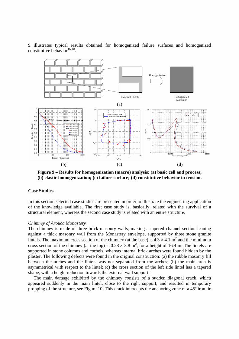
9 illustrates typical results obtained for homogenized failure surfaces and homogenized constitutive behavior16-18.
Basic cell (R.V.E.) Homogenised continuum
Homogenisation
(a)
(b) (c) (d)
Figure 9 – Results for homogenization (macro) analysis: (a) basic cell and process; (b) elastic homogenization; (c) failure surface; (d) constitutive behavior in tension.
Case Studies In this section selected case studies are presented in order to illustrate the engineering application of the knowledge available. The first case study is, basically, related with the survival of a structural element, whereas the second case study is related with an entire structure. Chimney of Arouca Monastery The chimney is made of three brick masonry walls, making a tapered channel section leaning against a thick masonry wall from the Monastery envelope, supported by three stone granite lintels. The maximum cross section of the chimney (at the base) is 4.3 × 4.1 m2 and the minimum cross section of the chimney (at the top) is 0.28 × 3.8 m2, for a height of 16.4 m. The lintels are supported in stone columns and corbels, whereas internal brick arches were found hidden by the plaster. The following defects were found in the original construction: (a) the rubble masonry fill between the arches and the lintels was not separated from the arches; (b) the main arch is asymmetrical with respect to the lintel; (c) the cross section of the left side lintel has a tapered shape, with a height reduction towards the external wall support19.
The main damage exhibited by the chimney consists of a sudden diagonal crack, which appeared suddenly in the main lintel, close to the right support, and resulted in temporary propping of the structure, see Figure 10. This crack intercepts the anchoring zone of a 45º iron tie
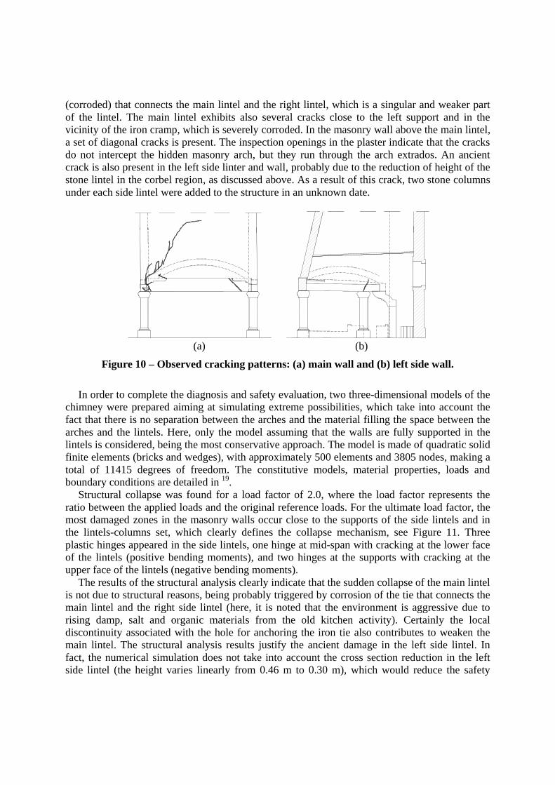
(corroded) that connects the main lintel and the right lintel, which is a singular and weaker part of the lintel. The main lintel exhibits also several cracks close to the left support and in the vicinity of the iron cramp, which is severely corroded. In the masonry wall above the main lintel, a set of diagonal cracks is present. The inspection openings in the plaster indicate that the cracks do not intercept the hidden masonry arch, but they run through the arch extrados. An ancient crack is also present in the left side linter and wall, probably due to the reduction of height of the stone lintel in the corbel region, as discussed above. As a result of this crack, two stone columns under each side lintel were added to the structure in an unknown date.
(a) (b)
Figure 10 – Observed cracking patterns: (a) main wall and (b) left side wall.
In order to complete the diagnosis and safety evaluation, two three-dimensional models of the
chimney were prepared aiming at simulating extreme possibilities, which take into account the fact that there is no separation between the arches and the material filling the space between the arches and the lintels. Here, only the model assuming that the walls are fully supported in the lintels is considered, being the most conservative approach. The model is made of quadratic solid finite elements (bricks and wedges), with approximately 500 elements and 3805 nodes, making a total of 11415 degrees of freedom. The constitutive models, material properties, loads and boundary conditions are detailed in 19.
Structural collapse was found for a load factor of 2.0, where the load factor represents the ratio between the applied loads and the original reference loads. For the ultimate load factor, the most damaged zones in the masonry walls occur close to the supports of the side lintels and in the lintels-columns set, which clearly defines the collapse mechanism, see Figure 11. Three plastic hinges appeared in the side lintels, one hinge at mid-span with cracking at the lower face of the lintels (positive bending moments), and two hinges at the supports with cracking at the upper face of the lintels (negative bending moments).
The results of the structural analysis clearly indicate that the sudden collapse of the main lintel is not due to structural reasons, being probably triggered by corrosion of the tie that connects the main lintel and the right side lintel (here, it is noted that the environment is aggressive due to rising damp, salt and organic materials from the old kitchen activity). Certainly the local discontinuity associated with the hole for anchoring the iron tie also contributes to weaken the main lintel. The structural analysis results justify the ancient damage in the left side lintel. In fact, the numerical simulation does not take into account the cross section reduction in the left side lintel (the height varies linearly from 0.46 m to 0.30 m), which would reduce the safety

factor significantly. This justifies the remedial measures adopted in the past by adding new stone columns close to the back supports of the side lintels.
(a) (b)
Figure 11 – Maximum principal strains (cracks), plotted in the deformed mesh at collapse: (a) brick masonry part; stone columns and lintels. Results are dimensionless.
The observed damage requires structural strengthening, which is complex due to the geometry
of the column capitals and the fact that stone granite is a facing material. This means that any strengthening applied externally would become visible and would be aesthetically rather unappealing. The other preliminary issue discussed with the client was the issue of removing or keeping the two additional stone columns installed as a previous remedial measure (date unknown but before the 20th century). Conservation principles are often used as an absolute prohibition against the removal of earlier repair work. But often it is possible to find examples of repairs that do not constitute a valid part of the history of the structure. In the present case, it is believed that the additional columns can indeed be removed from historical reasons but the additional complexity and costs to further strengthen the chimney advise not to take this action.
The final solution consists of strengthening and repairing the main lintel including: (a) reconstitution of the original stone integrity by injection of epoxy resins; (b) hole drilling of the stone along its full length (4.70 m); (c) insertion of bars and injection of the hole. Figure 12 illustrates various details of the solution, which includes two stainless steel rods with a diameter of 25 mm as internal ties / reinforcement of the granite lintel. The ties were designed after the integration of the tensile stresses of the linear elastic results for the numerical model without arching action, which is conservative. These rods are inserted in drilled holes of 50 mm and are provided with anchoring plates of 120 mm. After adjustment of the bolts, the drilled holes are injected with fluid lime mortar. Stone stoppers at both ends of the bottom tie are also included so that the anchoring plates are not visible. The stoppers are glued with epoxy resin and are made from the actual core removed from the lintel. It is noted that the usage of stone stoppers in both ends of the ties requires the drilling to be executed from both sides, which requires precision and qualified workers.
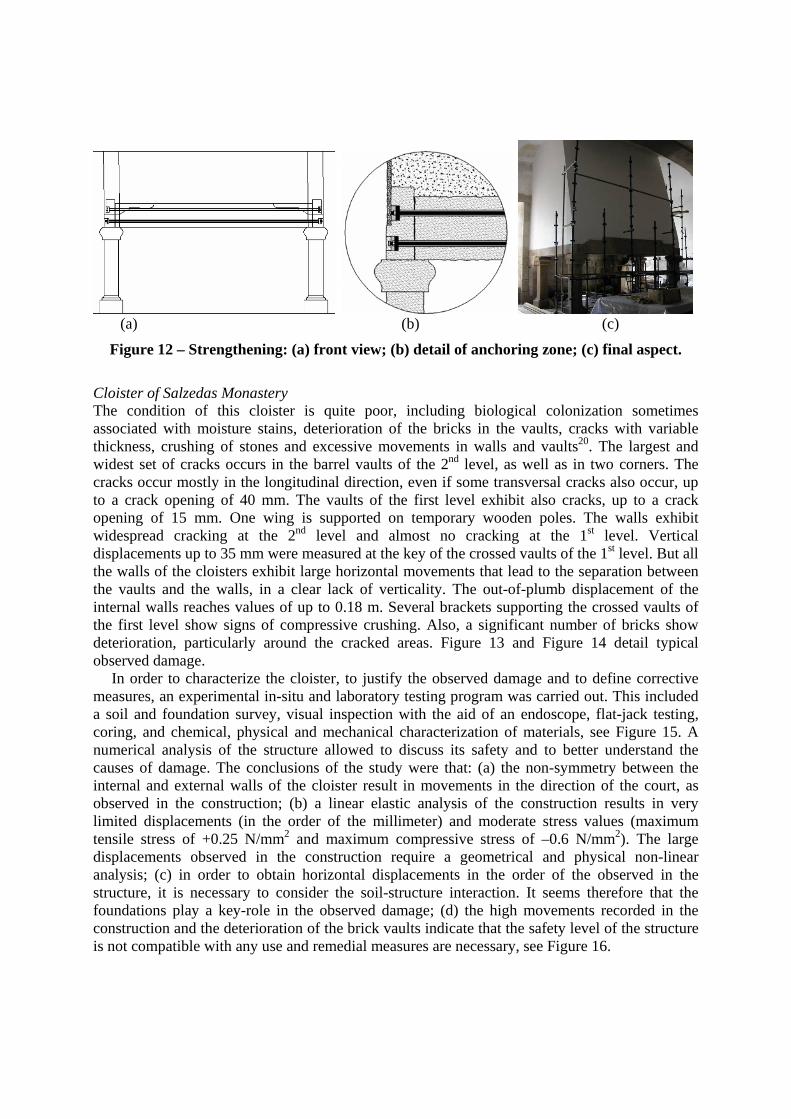
(a) (b) (c)
Figure 12 – Strengthening: (a) front view; (b) detail of anchoring zone; (c) final aspect.
Cloister of Salzedas Monastery The condition of this cloister is quite poor, including biological colonization sometimes associated with moisture stains, deterioration of the bricks in the vaults, cracks with variable thickness, crushing of stones and excessive movements in walls and vaults20. The largest and widest set of cracks occurs in the barrel vaults of the 2nd level, as well as in two corners. The cracks occur mostly in the longitudinal direction, even if some transversal cracks also occur, up to a crack opening of 40 mm. The vaults of the first level exhibit also cracks, up to a crack opening of 15 mm. One wing is supported on temporary wooden poles. The walls exhibit widespread cracking at the 2nd level and almost no cracking at the 1st level. Vertical displacements up to 35 mm were measured at the key of the crossed vaults of the 1st level. But all the walls of the cloisters exhibit large horizontal movements that lead to the separation between the vaults and the walls, in a clear lack of verticality. The out-of-plumb displacement of the internal walls reaches values of up to 0.18 m. Several brackets supporting the crossed vaults of the first level show signs of compressive crushing. Also, a significant number of bricks show deterioration, particularly around the cracked areas. Figure 13 and Figure 14 detail typical observed damage.
In order to characterize the cloister, to justify the observed damage and to define corrective measures, an experimental in-situ and laboratory testing program was carried out. This included a soil and foundation survey, visual inspection with the aid of an endoscope, flat-jack testing, coring, and chemical, physical and mechanical characterization of materials, see Figure 15. A numerical analysis of the structure allowed to discuss its safety and to better understand the causes of damage. The conclusions of the study were that: (a) the non-symmetry between the internal and external walls of the cloister result in movements in the direction of the court, as observed in the construction; (b) a linear elastic analysis of the construction results in very limited displacements (in the order of the millimeter) and moderate stress values (maximum tensile stress of +0.25 N/mm2 and maximum compressive stress of –0.6 N/mm2). The large displacements observed in the construction require a geometrical and physical non-linear analysis; (c) in order to obtain horizontal displacements in the order of the observed in the structure, it is necessary to consider the soil-structure interaction. It seems therefore that the foundations play a key-role in the observed damage; (d) the high movements recorded in the construction and the deterioration of the brick vaults indicate that the safety level of the structure is not compatible with any use and remedial measures are necessary, see Figure 16.

(a) (b)
(c) (d)
Figure 13 – Damage in the Salzedas’ cloister: (a) mapping of cracks (2nd level); (b) out-of-plane displacements; (c) aspect of vault (1st level); (d) aspect of vault (2nd level).
(a) (b) (c)
Figure 14 – Damage in the Salzedas’ cloister: (a) crushing of brackets; (b) deterioration of brick; (c) moisture stains and biological colonization.
Conclusions Significant knowledge is available in the context of modern testing and advanced analysis of masonry structures. Constraints to be considered in the use of advanced modeling are the cost,
the need of an experienced user / engineer, the level of accuracy required, the availability of input data, the need for validation and the use of the results. Obtained results are usually important for understanding the structural behavior of the constructions. But, as a rule, advanced modeling is only necessary in practice to understand the behavior and damage of (complex) constructions and to assist in the definition of rational safety assessment rules, based on a reliable and economical numerical laboratory. The key message of the paper is that research and innovation are strongly needed to assess the vulnerability of existing constructions and to define economical rational strengthening approaches. Without this, the ancient household and the preservation of the architectural heritage remain at risk.
(a) (b) (c) (d)
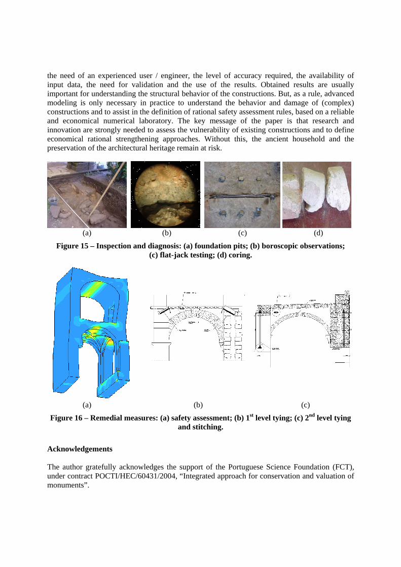
Figure 15 – Inspection and diagnosis: (a) foundation pits; (b) boroscopic observations; (c) flat-jack testing; (d) coring.
(a) (b) (c)
Figure 16 – Remedial measures: (a) safety assessment; (b) 1st level tying; (c) 2nd level tying and stitching.
Acknowledgements The author gratefully acknowledges the support of the Portuguese Science Foundation (FCT), under contract POCTI/HEC/60431/2004, “Integrated approach for conservation and valuation of monuments”.

References 1. Lourenço, P.B., 2002, Computations of historical masonry constructions, Progress in
Structural Engineering and Materials, 4(3), 301-319. 2. ICOMOS, 2001, Recommendations for the analysis, conservation and structural restoration
of architectural heritage. 3. CUR, 1997, Structural masonry: An experimental/numerical basis for practical design rules.
Rots J.G., editor. Rotterdam : Balkema. 4. Lourenço PB, 1998, Experimental and numerical issues in the modeling of the mechanical
behavior of masonry, In Roca et al. (ed.). Structural analysis of historical constructions, p. 57-91. Barcelona : CIMNE.
5. Oliveira, D.V., 2002, Experimental and numerical analysis of blocky masonry structures under cyclic loading. PhD Thesis. University of Minho (www.civil.uminho.pt/masonry).
6. Vasconcelos, G., 2005, Experimental investigations on the mechanics of stone masonry: characterization of granites and behaviour of ancient masonry walls. PhD Thesis. Guimarães : University of Minho. Available from www.civil.uminho.pt/masonry.
7. Lourenço, P.B., Almeida, J.C., Barros, J.A., 2005, Experimental investigation of bricks under uniaxial tensile testing, Masonry International, 18(1), p.11-20.
8. Lourenço, P.B., Ramos, L.F., 2004, Characterization of the cyclic behavior of dry masonry joints, J. Struct. Engrg., ASCE 130(5), p. 779-786.
9. Pina-Henriques, J.L., 2005, Masonry under compression: Failure analysis and long-term effects. PhD Thesis. University of Minho. Available from www.civil.uminho.pt/masonry.
10. Peña, F., Prieto, F., Lourenço, P.B., Campos Costa, A., 2006, On the Dynamics of Single Rigid–Block Structures. Part I: Experimental Testing, Earth. Engrg. Struc. Dyn. (submitted)
11. Prieto, F., Peña, F., Lourenço, P.B., Lemos, J.V., 2006, On the Dynamics of Single Rigid–Block Structures. Part II: Numerical Modeling, Earth. Engrg. Struc. Dyn. (submitted)
12. Lourenço, P.B., Rots, J.G., 1997, Multisurface interface model for the analysis of masonry structures, J. Engrg. Mech., ASCE, 123(7), p. 660-668.
13. Oliveira, D.V., Lourenço, P.B., 2004, Implementation and validation of a constitutive model for the cyclic behavior of interface elements, Comp. & Struct., 82 (17-19), p. 1451-1461.
14. Orduña, A., Lourenço, P.B., 2005, Three-dimensional limit analysis of rigid blocks assemblages. Part II: Load-path following solution procedure and validation, Int. J. Solids and Structures, 42(18-19), p. 5161-5180.
15. Lourenço, P.B., Rots J.G., Blaauwendraad J., 1998, Continuum model for masonry: Parameter estimation and validation, J. of Structural Engineering, 124(6), p. 642-652.
16. Zucchini, A., Lourenço, P.B., 2002, A micromechanical model for the homogenisation of masonry, Int. J. Solids and Structures, 39(12), p. 3233-3255
17. Zucchini, A., Lourenço, P.B., 2004, A coupled homogenisation-damage model for masonry cracking, Computers & Structures, 82, p. 917-929
18. Milani, G., Lourenço, P.B., Tralli, A., 2006, Homogenised limit analysis of masonry walls. Part I: Failure surfaces, Computers & Structures, 84(3-4), p. 181-195
19. Lourenço, P.B., 2006, Recommendations for restoration of ancient buildings and the survival of a masonry chimney, Construction and Building Materials, 20(4), p. 239-251.
20. Lourenço, P.B. et al., 2000, Diagnosis of the stability conditions of the XVII century cloister of the Monastery of Salzedas (in Portuguese). Report LEC 31/2000. University of Minho.