stroke saturation on a mems deformable mirror for woofer-tweeter adaptive optics
TRANSCRIPT

Stroke saturation on a MEMSdeformable mirror for woofer-tweeter
adaptive optics
Katie Morzinski,1,2∗ Bruce Macintosh,1,3 Donald Gavel,1,2 andDaren Dillon1,2
1 National Science Foundation Center for Adaptive Optics
2 UCO/Lick Observatory, 1156 High St., University of California, Santa Cruz, CA, 95064,USA
3 Lawrence Livermore National Laboratory, 7000 East Ave., Livermore, CA 94550, USA
Abstract: High-contrast imaging of extrasolar planet candidates around amain-sequence star has recently been realized from the ground using currentadaptive optics (AO) systems. Advancing such observations will be a taskfor the Gemini Planet Imager, an upcoming “extreme” AO instrument.High-order “tweeter” and low-order “woofer” deformable mirrors (DMs)will supply a >90%-Strehl correction, a specialized coronagraph will sup-press the stellar flux, and any planets can then be imaged in the “dark hole”region. Residual wavefront error scatters light into the DM-controlled darkhole, making planets difficult to image above the noise. It is crucial in thisregard that the high-density tweeter, a micro-electrical mechanical systems(MEMS) DM, have sufficient stroke to deform to the shapes requiredby atmospheric turbulence. Laboratory experiments were conducted todetermine the rate and circumstance of saturation, i.e. stroke insufficiency.A 1024-actuator 1.5-μm-stroke MEMS device was empirically tested withsoftware Kolmogorov-turbulence screens of r0 =10–15 cm. The MEMSwhen solitary suffered saturation ∼4% of the time. Simulating a woofer DMwith ∼5–10 actuators across a 5-m primary mitigated MEMS saturationoccurrence to a fraction of a percent. While no adjacent actuators weresaturated at opposing positions, mid-to-high-spatial-frequency stroke didsaturate more frequently than expected, implying that correlations throughthe influence functions are important. Analytical models underpredict thestroke requirements, so empirical studies are important.
© 2009 Optical Society of America
OCIS codes: (010.1080) Active or adaptive optics; (230.4685) Optical microelectromechanicaldevices; (350.1260) Astronomical optics; (010.1285) Atmospheric correction
References and links1. C. Marois, B. Macintosh, T. Barman, B. Zuckerman, I. Song, J. Patience, D. Lafreniere, and R. Doyon, “Direct
imaging of multiple planets orbiting the star HR 8799,” Science 322, 1348–1352 (2008).2. P. Kalas, J. R. Graham, E. Chiang, M. P. Fitzgerald, M. Clampin, E. S. Kite, K. Stapelfeldt, C. Marois, and J.
Krist, “Optical Images of an Exosolar Planet 25 Light-Years from Earth,” Science 322, 1345–1348 (2008).
#106782 - $15.00 USD Received 23 Jan 2009; revised 13 Mar 2009; accepted 14 Mar 2009; published 26 Mar 2009
(C) 2009 OSA 30 March 2009 / Vol. 17, No. 7 / OPTICS EXPRESS 5829

3. A.-M. Lagrange, D. Gratadour, G. Chauvin, T. Fusco, D. Ehrenreich, D. Mouillet, G. Rousset, D. Rouan, F.Allard, E. Gendron, J. Charton, L. Mugnier, P. Rabou, J. Montri, and F. Lacombe, ”A probable giant planetimaged in the β Pictoris disk. VLT/NaCo deep L’-band imaging,” Astron. Astrophys. 493, L21–L25 (2009).
4. C. Marois, D. Lafreniere, R. Doyon, B. Macintosh, and D. Nadeau, “Angular Differential Imaging: A powerfulhigh-contrast imaging technique,” Astrophys. J. 641, 556–564 (2006).
5. B. A. Macintosh, J. R. Graham, D. W. Palmer, R. Doyon, J. Dunn, D. T. Gavel, J. Larkin, B. Oppenheimer, L.Saddlemyer, A. Sivaramakrishnan, J. K. Wallace, B. Bauman, D. A. Erickson, C. Marois, L. A. Poyneer, andR. Soummer, “The Gemini Planet Imager: From science to design to construction,” Proc. SPIE 7015, 701518(2008).
6. P. Kalas, “GPI: Gemini Planet Imager,” http://gpi.berkeley.edu.7. S. A. Cornelissen, P. A. Bierden, T. G. Bifano, “A 4096 element continuous facesheet MEMS deformable mirror
for high-contrast imaging,” Proc. SPIE 6888, 68880V-1–10 (2008).8. K. M. Morzinski, D. T. Gavel, A. P. Norton, D. R. Dillon, and M. R. Reinig, “Characterizing MEMS deformable
mirrors for open-loop operation: High-resolution measurements of thin-plate behavior,” Proc. SPIE 6888, 68880S(2008a).
9. K. M. Morzinski, J. W. Evans, S. Severson, B. Macintosh, D. Dillon, D. Gavel, C. Max, and D. Palmer, “Charac-terizing the potential of MEMS deformable mirrors for astronomical adaptive optics,” Proc. SPIE 6272, 627221(2006).
10. J. W. Evans, B. Macintosh, L. Poyneer, K. Morzinski, S. Severson, D. Dillon, D. Gavel, and L. Reza, “Demon-strating sub-nm closed loop MEMS flattening,” Opt. Express 14, 5558–5570 (2006).
11. J. W. Evans, K. Morzinski, L. Reza, S. Severson, L. Poyneer, B. A. Macintosh, D. Dillon, G. Sommargren, D.Palmer, D. Gavel, and S. Olivier, “Extreme adaptive optics testbed: High contrast measurements with a MEMSdeformable mirror,” Proc. SPIE 5905, 59050Y (2005).
12. D. Gavel, S. Severson, B. Bauman, D. Dillon, M. Reinig, C. Lockwood, D. Palmer, K. Morzinski, M. Ammons,E. Gates, and B. Grigsby, “Villages: An on-sky visible wavelength astronomy AO experiment using a MEMSdeformable mirror,” Proc. SPIE 6888, 688804 (2008).
13. D. Gavel, M. Ammons, B. Bauman, D. Dillon, E. Gates, B. Grigsby, J. Johnson, C. Lockwood, K. Morzinski, D.Palmer, M. Reinig, and S. Severson, “Visible light laser guidestar experimental system (Villages): On-sky testsof new technologies for visible wavelength all-sky coverage adaptive optics systems,” Proc. SPIE 7015, 70150G(2008).
14. F. Malbet, J. W. Yu, and M. Shao, “High-dynamic-range imaging using a deformable mirror for space coronog-raphy,” Publ. Astron. Soc. Pac. 107, 386–398 (1995).
15. R. Soummer, “Apodized pupil Lyot coronagraphs for arbitrary telescope apertures,” Astrophys. J. L. 618, L161–L164 (2005).
16. S. J. Thomas, R. Soummer, D. Dillon, B. Macintosh, J. W. Evans, D. Gavel, A. Sivaramakrishnan, C. Marois,and B. R. Oppenheimer, “Testing the APLC on the LAO ExAO testbed,” Proc. SPIE 7015, 701561 (2008).
17. K. M. Morzinski, B. A. Macintosh, D. Dillon, D. Gavel, D. Palmer, and A. Norton, “Empirical measurementof MEMS stroke saturation, with implications for woofer-tweeter architectures,” Proc. SPIE 7015, 70153N–70153N-12 (2008b).
18. A. Norton, J. W. Evans, D. Gavel, D. Dillon, D. Palmer, B. Macintosh, K. Morzinski, S. Cornelissen, “Preliminarycharacterization of Boston Micromachines’ 4096-actuator deformable mirror,” Proc. SPIE 7209, 720916 (2009).
19. S. A. Severson, Department of Physics and Astronomy, Sonoma State University, 300L Darwin Hall, RohnertPark, CA 94928, (personal communication, 2006).
20. V. I. Tatarski, Wave propagation in a turbulent medium (McGraw-Hill Book Company, Inc., 1961).21. J. W. Hardy, “Instrumental limitations in adaptive optics for astronomy,” Proc. SPIE 1114, 2–13 (1989).22. R. J. Noll, “Zernike polynomials and atmospheric turbulence,” J. Opt. Soc. Am. 66, 207–211 (1976).23. R. Hudgin, “Wave-front compensation error due to finite corrector-element size,” J. Opt. Soc. Am. 67, 393–395
(1977).24. J. W. Hardy, Adaptive optics for astronomical telescopes (Oxford University Press, 1998).25. R. Conan, “Mean-square residual error of a wavefront after propagation through atmospheric turbulence and after
correction with Zernike polynomials,” J. Opt. Soc. Am. A 25, 526–536 (2008).26. J.-F. Lavigne and J.-P. Veran, “Woofer-tweeter control in an adaptive optics system using a Fourier reconstructor,”
J. Opt. Soc. Am. A 25, 2271–2279 (2008).27. G. E. Sommargren, D. W. Phillion, M. A. Johnson, N. Q. Nguyen, A. Barty, F. J. Snell, D. R. Dillon and L. S.
Bradsher, “100-picometer interferometry for EUVL,” Proc. SPIE 4688, 316–328 (2002).28. J. W. Evans, K. Morzinski, S. Severson, L. Poyneer, B. Macintosh, D. Dillon, L. Reza, D. Gavel, D. Palmer, S.
Olivier, and P. Bierden, “Extreme adaptive optics testbed: Performance and characterization of a 1024-MEMSdeformable mirror,” Proc. SPIE 6113, 61130I (2006).
29. S. A. Severson, B. Bauman, D. Dillon, J. Evans, D. Gavel, B. Macintosh, K. Morzinski, D. Palmer, and L.Poyneer, “The extreme adaptive optics testbed at UCSC: Current results and coronagraphic upgrade,” Proc. SPIE6272, 62722J (2006).
30. R. Conan, C. Bradley, P. Hampton, O. Keskin, A. Hilton, C. Blain, “Distributed modal command for a two-
#106782 - $15.00 USD Received 23 Jan 2009; revised 13 Mar 2009; accepted 14 Mar 2009; published 26 Mar 2009
(C) 2009 OSA 30 March 2009 / Vol. 17, No. 7 / OPTICS EXPRESS 5830

deformable-mirror adaptive optics system,” Appl. Opt. 46, 4329–4340 (2007).31. K. Morzinski, K. B. W. Harpsøe, D. Gavel, S. M. Ammons, “The open-loop control of MEMS: Modeling and
experimental results,” Proc. SPIE 6467, 64670G, (2007).32. C. R. Vogel and Q. Yang, “Modeling, simulation, and open-loop control of a continuous facesheet MEMS de-
formable mirror,” J. Opt. Soc. Am. A 23, 1074–1081 (2006).33. J. B. Stewart, A. Diouf, Y. Zhou, and T. G. Bifano, “Open-loop control of a MEMS deformable mirror for large-
amplitude wavefront control,” J. Opt. Soc. Am. A 24, 3827–3833 (2007).
1. Introduction
Direct imaging of extrasolar planet candidates around main-sequence stars has recently beenrealized[1, 2, 3] employing current adaptive optics (AO) systems and the angular differentialimaging technique[4]. Such high-contrast observations with ground-based telescopes requirecareful control of the incident wavefront, eliminating noise so that faint sources can be detected.Designed specifically for high-contrast imaging, the Gemini Planet Imager (GPI)[5, 6] will usean “extreme” adaptive optics (ExAO) system to flatten the incident wavefront.
Key to this ExAO system is the high-order deformable mirror (DM), a polysiliconmicro-electrical mechanical systems (MEMS) DM developed by Boston MicromachinesCorporation[7]. Consisting of thousands of individually addressable actuators in a coin-sizedspace, MEMS DMs are a low-cost approach to high-order wavefront correction; however,MEMS devices exhibit less mechanical stroke than conventional piezo-actuated DMs.
Stroke saturates when the desired DM shape at a given actuator is beyond that actuator’srange of motion. Saturation degrades the wavefront correction and scatters light into the regionthat should remain dark for detection of faint sources. This paper evaluates avoiding strokesaturation through addition of a second low-order, high-stroke DM in tandem with the MEMSDM.
2. Background
MEMS devices were chosen as the high-order wavefront corrector for GPI because of theircost-effectiveness, high-actuator density, and agreeable performance. The mirrors can be batch-fabricated using a silicon foundry approach similar to that used to make integrated circuits, fora cost an order of magnitude cheaper per actuator than that of traditional piezoelectric DMs.MEMS technology is scalable to the actuator count required for ExAO high-contrast imaging.
A series of prototype MEMS devices (two 144-element, ten 1024-element, and two 4096-element DMs) has been thoroughly tested at the University of California at Santa Cruz’s Lab-oratory for Adaptive Optics (LAO). At the sub-nanometer level, hysteresis is negligible[8] andMEMS devices are temporally stable and precisely positionable[9]. A MEMS DM has beenflattened to 0.54 nm rms in the control band[10] and has achieved 10−6 contrast at the farfield[11]. An AO system using a 144-actuator MEMS DM has been successfully tested on-sky at Lick Observatory[12, 13]. Figure 1 shows the LAO’s first 4096-actuator DM, called an“engineering-grade” device because it is useable for testing and characterizing but is not fullyfunctional across the mirror as required for GPI’s “science-grade” MEMS.
Residual low-frequency wavefront error in the GPI optical train will scatter star light into theregion of the focal plane that should be kept dark in order to detect planets. This is often referredto as the “dark hole” region, and its size is set by the smallest-spatial-frequency control band,i.e. the spacing of the MEMS actuators in the Fourier domain[14]. Actuators on the deformablemirror that are broken, dead, or stuck scatter light into the dark hole by virtue of their influencefunctions producing a wide PSF in the far-field image. Saturated actuators are problematic forhigh-contrast imaging because, optically, insufficient stroke has the same effect as a broken,dead, or stuck actuator.
#106782 - $15.00 USD Received 23 Jan 2009; revised 13 Mar 2009; accepted 14 Mar 2009; published 26 Mar 2009
(C) 2009 OSA 30 March 2009 / Vol. 17, No. 7 / OPTICS EXPRESS 5831
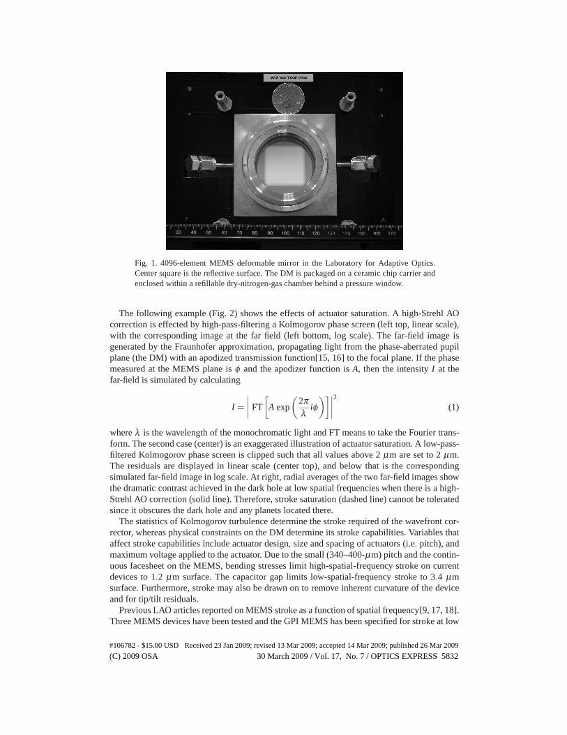
Fig. 1. 4096-element MEMS deformable mirror in the Laboratory for Adaptive Optics.Center square is the reflective surface. The DM is packaged on a ceramic chip carrier andenclosed within a refillable dry-nitrogen-gas chamber behind a pressure window.
The following example (Fig. 2) shows the effects of actuator saturation. A high-Strehl AOcorrection is effected by high-pass-filtering a Kolmogorov phase screen (left top, linear scale),with the corresponding image at the far field (left bottom, log scale). The far-field image isgenerated by the Fraunhofer approximation, propagating light from the phase-aberrated pupilplane (the DM) with an apodized transmission function[15, 16] to the focal plane. If the phasemeasured at the MEMS plane is φ and the apodizer function is A, then the intensity I at thefar-field is simulated by calculating
I =∣∣∣∣
FT
[
A exp
(2πλ
iφ)]∣
∣∣∣
2
(1)
where λ is the wavelength of the monochromatic light and FT means to take the Fourier trans-form. The second case (center) is an exaggerated illustration of actuator saturation. A low-pass-filtered Kolmogorov phase screen is clipped such that all values above 2 μm are set to 2 μm.The residuals are displayed in linear scale (center top), and below that is the correspondingsimulated far-field image in log scale. At right, radial averages of the two far-field images showthe dramatic contrast achieved in the dark hole at low spatial frequencies when there is a high-Strehl AO correction (solid line). Therefore, stroke saturation (dashed line) cannot be toleratedsince it obscures the dark hole and any planets located there.
The statistics of Kolmogorov turbulence determine the stroke required of the wavefront cor-rector, whereas physical constraints on the DM determine its stroke capabilities. Variables thataffect stroke capabilities include actuator design, size and spacing of actuators (i.e. pitch), andmaximum voltage applied to the actuator. Due to the small (340–400-μm) pitch and the contin-uous facesheet on the MEMS, bending stresses limit high-spatial-frequency stroke on currentdevices to 1.2 μm surface. The capacitor gap limits low-spatial-frequency stroke to 3.4 μmsurface. Furthermore, stroke may also be drawn on to remove inherent curvature of the deviceand for tip/tilt residuals.
Previous LAO articles reported on MEMS stroke as a function of spatial frequency[9, 17, 18].Three MEMS devices have been tested and the GPI MEMS has been specified for stroke at low
#106782 - $15.00 USD Received 23 Jan 2009; revised 13 Mar 2009; accepted 14 Mar 2009; published 26 Mar 2009
(C) 2009 OSA 30 March 2009 / Vol. 17, No. 7 / OPTICS EXPRESS 5832

Fig. 2. Illustration of the consequences of stroke saturation. Left top: High-pass-filteredKolmogorov phase screen, linear scale, and its simulated far-field image (left bottom), logscale. Center top: Exaggerated simulation of saturation with clipped Kolmogorov phasescreen, linear scale, and its simulated far-field image (center bottom), log scale. Right:Radial averages of the simulated far-field images. Solid line: High-Strehl AO correction.Dashed line: Stroke saturated above 2 μm.
and high spatial frequencies; Table 1 compiles the results. Norton et al.[18] give more details ofthe “engineering-grade” 4k-MEMS characterization. The GPI “science-grade” 4k-MEMS hasnot yet been delivered, but its specifications are given.
Table 1. Stroke measurements for a variety of MEMS DMs in the Laboratory for AdaptiveOptics[17]. †W107#X at a maximum voltage of 200 V is the same MEMS device used forthe Kolmogorov saturation experiments described in Section 4.
MEMS Actuator Pitch Max. Volt. Low-freq. stroke High-freq. strokeDevice Count [μm] Applied [μm surface] [μm surface]
Empirical MeasurementsW107#X 1024 340 160 1.0 0.2W107#X† 1024 340 200 1.5 0.2W95#39 1024 400 200 3.2 0.94kEng#1 4096 400 225 3.4 1.2Specifications
GPI 4k 4096 400 260 4.0 1.0
To measure MEMS stroke at a range of spatial frequencies, one-dimensional sinusoids ofvarying period were applied to two 1024-actuator DMs, and the resulting stroke was measuredin each case[9, 17]. The results are plotted in Fig. 3 for the devices W107#X (pitch 340 μmand tested on the voltage range 0–160 V) and W95#39 (pitch 400 μm and tested on the voltagerange 0–200 V). MEMS stroke decreases with increasing spatial frequency, whereas a hori-zontal line on Fig. 3 would be produced by both a segmented mirror and a DM with actuatorshaving narrow sinc influence functions (with the first zero occurring at a spacing of one actua-tor away). This departure from the narrow-sinc case indicates that the broad MEMS influencefunctions[19] have the effect of reducing the stroke as spatial frequency increases.
Rather than plotting a single line with each data series on Fig. 3, two line segments joined
#106782 - $15.00 USD Received 23 Jan 2009; revised 13 Mar 2009; accepted 14 Mar 2009; published 26 Mar 2009
(C) 2009 OSA 30 March 2009 / Vol. 17, No. 7 / OPTICS EXPRESS 5833

by a “knee” fit each measurement series better. The knee in both cases is located around 9cycles per aperture, a 3.6-actuator period, while the influence function measured for a 340-μm-pitch MEMS falls to 4% at 2 actuators away[19], about half this period. This implies that thehigh-spatial-frequency stroke is controlled locally by neighboring-actuators’ influence func-tions, whereas the low-spatial-frequency stroke is in a distinct whole-MEMS regime.
Fig. 3. LAO testing of stroke as a function of spatial frequency for two MEMS deformablemirrors. Diamonds: Device W107#X, pitch 340 μm, voltage range 0–160 V. Plus-signs:Device W95#39, pitch 400 μm, voltage range 0–200 V. The “knee” is located around 9cycles per aperture for both devices. Note that a DM having sinc influence functions thatfall to zero one actuator away would produce a horizontal line on this plot, as would asegmented mirror.
3. Theory
In a woofer-tweeter architecture, two DMs are arranged in series and both are conjugate to thesame optical plane, usually that of the telescope pupil. The low-actuator-count, high-stroke DMis termed the “woofer,” and the high-actuator-count, low-stroke DM is the “tweeter,” a MEMSin the case of GPI. As a consequence of the Kolmogorov turbulence spectrum, atmospheric tur-bulence strength decreases with spatial frequency[20], making the woofer-tweeter architecturefeasible. The woofer DM corrects the higher-stroke, lower-spatial-frequency aberrations whilethe tweeter corrects the lower-stroke, higher-spatial-frequency aberrations.
From Kolmogorov turbulence theory one can calculate the expected stroke requirement for adeformable mirror at a given telescope[21]. At Gemini South, the planned location of GPI, theprimary is D = 8 m and a typical Fried parameter is r0 = 14 cm. The power spectral density Φof Kolmogorov turbulence goes as Φ(κ) ∝ κ−5/3, where κ is the wave number. The formula
#106782 - $15.00 USD Received 23 Jan 2009; revised 13 Mar 2009; accepted 14 Mar 2009; published 26 Mar 2009
(C) 2009 OSA 30 March 2009 / Vol. 17, No. 7 / OPTICS EXPRESS 5834
for fitting error in radians σF as a function of r0 and the actuator spacing d is
σ2F = αF
(dr0
)5/3
, (2)
where αF is a constant that depends on the influence function for the deformable mirror inquestion[22, 23].
For a continuous facesheet DM, αF = 0.14 for circular segments with piston and tip/tiltactuation capabilities[24]. Let us take this value for αF , put the primary diameter D = d = 8 m,r0 = 14 cm, and λ = 500 nm. To calculate the total stroke requirement, we convert Equation 2from square radians to microns surface, and multiply by 5 to obtain a ±5σ correction:
σF = (±5)(
12
)(λ2π
)√αF
(Dr0
)5/6
= ±2.17 μm surface = 4.3 μm surface P−V. (3)
The factor of 1/2 converts from phase to surface and λ/(2π) converts from radians to microns.However, 4.3 μm surface is the stroke requirement at the center of the pupil, and due to factorsincluding non-stationarity of phase[25] (which adds 20% at the edges of the pupil), inherentcurvature of the MEMS (on the order of a few μm for current devices), and tip/tilt residuals, upto ∼ 10 μm stroke is desired[26]. From Table 1 we see that the 4k-MEMS devices do not getas much as 10 μm stroke, so it was determined that a woofer DM was needed.
Equation 2 can also be used to calculate the residuals after applying a woofer, which givesthe stroke requirement for the tweeter in microns surface:
σF =(
12
)(λ2π
)√αF
(dwoo f
r0
)5/6
, (4)
where dwoo f is the woofer actuator spacing. In this case the αF parameter becomes 0.28—appropriate for the influence function of a continuous facesheet DM[24].
Varying dwoo f in Equation 4 and multiplying the final result by ±3–5 to get the 3–5-sigmastroke requirement, the tweeter stroke required for each woofer degree of freedom is plotted inFig. 4. Note that the stroke requirement quoted above of 10 μm is for a 8-m pupil and r0 = 14 cmwhile Fig. 4 is for a 5-m pupil and r0 = 15 cm. For the parameters in Fig. 4, using a woofermitigates the tweeter stroke requirement to a more manageable ∼1μm surface. Total stroke
required rises as D56 with primary diameter (i.e. Equation 3), which increases the requirement
on the woofer but not the tweeter. Rather, tweeter stroke is a function of the woofer pitch,not the primary diameter. Therefore, experiments simulating a 5-m pupil are still valid for the8-m pupil case in regards to the tweeter. Laboratory experiments follow to verify empiricallythe ability of the MEMS to form Kolmogorov atmosphere shapes, using a woofer to avoidsaturation.
4. Experiment
We tested MEMS device W107#X for stroke saturation when being deformed to correct forKolmogorov turbulence. W107#X has a 340-μm pitch and was applied with a maximum volt-age of 200 V. From Table 1, we see its low-order stroke is 1.5 μm surface and its high-orderstroke is 0.2 μm surface. While this DM does not have as much stroke as the final GPI 4k-MEMS will, the experiments are useful in determining whether inter-actuator or peak-to-valleystroke causes more saturation events.
Device W107#X has 1024 actuators (32 across) rather than the 44-actuators-across GPI willuse. Thus, because the high spatial frequencies on the MEMS were of more interest than the
#106782 - $15.00 USD Received 23 Jan 2009; revised 13 Mar 2009; accepted 14 Mar 2009; published 26 Mar 2009
(C) 2009 OSA 30 March 2009 / Vol. 17, No. 7 / OPTICS EXPRESS 5835

Fig. 4. Tweeter stroke required as a function of woofer degrees of freedom for r0 = 15 cm,based on Equation 4.
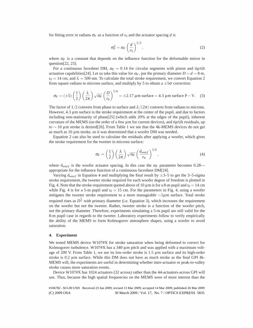
low, the MEMS pitch with respect to the primary was held fixed at the GPI value (18 cm), mean-ing the size of the pupil in this experiment corresponds to a 5-m telescope. The comparativemapping between the MEMS actuators and the telescope pupils is shown in Fig. 5, superim-posed over a Kolmogorov phase screen. The entire square image contains 44x44 actuators,the outer inscribed circle delineates an 8-m pupil (GPI), the inner black square marks 32x32actuators, and the inner inscribed circle delineates a 5-m pupil (this laboratory experiment).
Measurements were made using the phase-shifting diffraction interferometer[27], a sub-nanometer-absolute-accuracy measuring instrument situated on the ExAO testbed[28, 29] atthe LAO. A spherical wave (f/220) converges from a beam size of 12 mm at the MEMS planeto the surface of a pinhole aligner, where it is combined with a reference beam. The referencebeam emerges from a fiber in spherical waves, emitted through the 2.5-μm pinhole to interferewith the reflected test beam. This reference wave has an excellent wavefront quality (λ/500)with which to compare the test beam. The resulting diverging spherical wave fringes are imagedon a CCD camera. The interferogram is numerically back-propagated using a Huygens methodto obtain phase and amplitude data at the MEMS plane.
The free parameters in the saturation experiment were the Fried coherence size, r0, and thewoofer pitch, dwoo f . The procedure was as follows: An atmospheric turbulence screen with thespecified r0 was generated in software by enforcing Kolmogorov turbulence statistics upon anarray of random numbers. Compensation of the atmosphere screen by an ideal woofer DM withthe specified dwoo f was simulated by removing all the power at low spatial frequencies belowthe appropriate cutoff frequency in the Fourier domain. The resultant phase screen containedonly the higher spatial frequencies. The MEMS was then “closed to” this turbulence screenin closed-loop by using the screen as the reference. That is, rather than taking a flat shape asthe target of the closed-loop algorithm, the target for convergence was the phase screen. After
#106782 - $15.00 USD Received 23 Jan 2009; revised 13 Mar 2009; accepted 14 Mar 2009; published 26 Mar 2009
(C) 2009 OSA 30 March 2009 / Vol. 17, No. 7 / OPTICS EXPRESS 5836
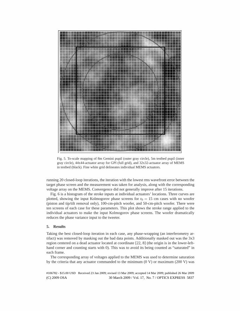
Fig. 5. To-scale mapping of 8m Gemini pupil (outer gray circle), 5m testbed pupil (innergray circle), 44x44-actuator array for GPI (full grid), and 32x32-actuator array of MEMSin testbed (black). Fine white grid delineates individual MEMS actuators.
running 20 closed-loop iterations, the iteration with the lowest rms wavefront error between thetarget phase screen and the measurement was taken for analysis, along with the correspondingvoltage array on the MEMS. Convergence did not generally improve after 15 iterations.
Fig. 6 is a histogram of the stroke inputs at individual actuators’ locations. Three curves areplotted, showing the input Kolmogorov phase screens for r0 = 15 cm cases with no woofer(piston and tip/tilt removal only), 100-cm-pitch woofer, and 50-cm-pitch woofer. There wereten screens of each case for these parameters. This plot shows the stroke range applied to theindividual actuators to make the input Kolmogorov phase screens. The woofer dramaticallyreduces the phase variance input to the tweeter.
5. Results
Taking the best closed-loop iteration in each case, any phase-wrapping (an interferometry ar-tifact) was removed by masking out the bad data points. Additionally masked out was the 3x3region centered on a dead actuator located at coordinate [22, 8] (the origin is in the lower-left-hand corner and counting starts with 0). This was to avoid its being counted as “saturated” ineach frame.
The corresponding array of voltages applied to the MEMS was used to determine saturationby the criteria that any actuator commanded to the minimum (0 V) or maximum (200 V) was
#106782 - $15.00 USD Received 23 Jan 2009; revised 13 Mar 2009; accepted 14 Mar 2009; published 26 Mar 2009
(C) 2009 OSA 30 March 2009 / Vol. 17, No. 7 / OPTICS EXPRESS 5837
Fig. 6. Histogram of individual actuator phases input for the r0 = 15 cm experiment. Dashedline: No woofer (piston and tip/tilt removal only); Dashed-dotted line: 100-cm-pitch woofercorrection; Solid line: 50-cm-pitch woofer correction.
declared “saturated.” Table 2 lists the set of parameters explored and gives the number of ac-tuators saturated. The number of actuators tested varies due to different numbers of trials anddifferent numbers of actuators remaining within the unmasked region after discarding phase-wrapped data. For r0 = 10 cm and dwoo f = 31 cm, zero actuators were saturated out of the 4852tested. Therefore, the probability of saturation in that case was calculated using the binomialtheorem and taking the outside-3-σ probability for the upper limit. Figure 7 plots the satura-tion frequency as a function of woofer pitch for r0 = 10–15 cm. Error bars are standard error(σ/
√N). A power law is fit to each series.
Actuator voltage maps give a qualitative picture of close saturation encounters for the MEMSin closing to a Kolmogorov phase screen. Figure 8 shows three typical actuator voltage maps.Saturated actuators are identified with a white cross (saturated low) or a black diamond (sat-urated high). The first case is a typical iteration for r0 = 10 cm and no woofer (piston andtip/tilt removal only). The mean number of saturated actuators for these parameters was 16 pertrial, and this particular iteration has three actuators saturated high and eleven saturated low.The second case is a typical iteration for r0 = 10 cm and dwoo f = 134 cm. The mean numberof saturated actuators for these parameters was two per trial, and this particular iteration hastwo actuators saturated low and none saturated high. The third case is a typical iteration forr0 = 10 cm and dwoo f = 62 cm. The mean number of saturated actuators for these parameterswas one per trial, and this particular iteration has one actuator saturated low and none saturatedhigh.
Besides using these actuator voltage maps to display the number of saturated actuators, wealso notice something qualitative yet important with these plots: saturated actuators occur eithersingly or else in clumps. They do not, however, occur in pairs of one up and one down: in theclumpy patches of saturated actuators, all members of the saturated clump are either high or low.In all, 140 trials total were done (57 046 actuators were tested after masking out bad data), andthere are no instances of two adjacent saturated actuators in which one was saturated high andthe other low. Thus, the most extreme case of inter-actuator saturation at opposing positions
#106782 - $15.00 USD Received 23 Jan 2009; revised 13 Mar 2009; accepted 14 Mar 2009; published 26 Mar 2009
(C) 2009 OSA 30 March 2009 / Vol. 17, No. 7 / OPTICS EXPRESS 5838
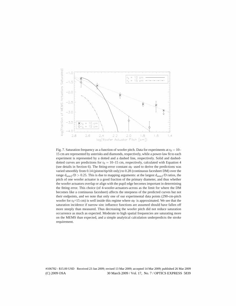
Fig. 7. Saturation frequency as a function of woofer pitch. Data for experiments at r0 = 10–15 cm are represented by asterisks and diamonds, respectively, while a power-law fit to eachexperiment is represented by a dotted and a dashed line, respectively. Solid and dashed-dotted curves are predictions for r0 = 10–15 cm, respectively, calculated with Equation 4(see details in Section 6). The fitting-error constant αF used to derive the predictions wasvaried smoothly from 0.14 (piston/tip/tilt only) to 0.28 (continuous facesheet DM) over therange dwoo f /D > 0.25. This is due to mapping arguments: at the largest dwoo f /D ratios, thepitch of one woofer actuator is a good fraction of the primary diameter, and thus whetherthe woofer actuators overlap or align with the pupil edge becomes important in determiningthe fitting error. This choice (of 4-woofer-actuators-across as the limit for where the DMbecomes like a continuous facesheet) affects the steepness of the predicted curves but nottheir endpoints, and we note that only one of our experimental data points (290-cm-pitchwoofer for r0=15 cm) is well inside this regime where αF is approximated. We see that thesaturation incidence if narrow sinc influence functions are assumed should have fallen offmore steeply than measured. Thus decreasing the woofer pitch did not reduce saturationoccurrence as much as expected. Moderate to high spatial frequencies are saturating moreon the MEMS than expected, and a simple analytical calculation underpredicts the strokerequirement.
#106782 - $15.00 USD Received 23 Jan 2009; revised 13 Mar 2009; accepted 14 Mar 2009; published 26 Mar 2009
(C) 2009 OSA 30 March 2009 / Vol. 17, No. 7 / OPTICS EXPRESS 5839

Table 2. Stroke saturation results: Fraction of actuators saturated for each set of (r0, dwoo f )parameters, after removing piston and tip/tilt. The number of actuators tested in each case isequal to the total number of MEMS actuators within the pupil, summed over all trials. Thisquantity varies according to two effects: there is a non-uniform number of trials conductedfor each set of parameters, and there is a non-uniform number of actuators analyzed insidethe pupil for each trial. The pupil nominally encircles ∼ 600 actuators, but actuators aremasked out and not counted if they are in regions where phase-wrapping occurs in theinterferometric measurement. �At the largest woofer-pitch end, no woofer was used—onlypiston and tip/tilt were removed over a 5-m aperture. We therefore adopted “500 cm” asthe abscissa for these data to be able to plot the corresponding ordinate from column 4 ontoFig. 7. †Upper limit.
r0 Woofer Pitch # Actuators Frac. Saturated Actuators[cm] [cm] Tested [parts per thousand]10 31 4852 0.01†
10 40 4359 2.210 62 12 943 2.510 134 6228 7.010 290 2790 2110 piston/tip/tilt� 9494 4615 50 5699 0.1715 100 5620 0.3715 piston/tip/tilt� 5061 30
is not occurring. However, we will see below that moderate to high spatial frequencies wereproblematic in another sense.
Figure 9 shows the peak-to-valley stroke histogram for various woofer pitches, as noted inthe legend. The trials without a woofer (piston and tip/tilt removal only) had a peak-to-valleystroke ranging from 0.8 to 1.7 μm surface. Using a woofer reduces the peak-to-valley strokerequired of the MEMS by a factor of 3–4, down to 0.2 to 0.5 μm surface. Note that a maximumof 1.5 μm surface stroke was measured for this MEMS, device W107#X (Table 1), in the low-frequency stroke test. Obtaining more stroke, up to 1.7 μm surface, with a Kolmogorov phasescreen is attributed to the curvature of the inherent shape of the MEMS, which is 450 nm surfacefor this device.
Figure 10 shows the inter-actuator stroke histogram for the same cases. Inter-actuator strokeis calculated by differencing the measured phase between each pair of neighboring actuators.Neighbors to a particular actuator are horizontally, vertically, or diagonally adjacent to thatactuator. The woofer reduces the required inter-actuator stroke by a factor of 2–3, a smallerimprovement than the peak-to-valley reduction. This is as expected because the woofer actuatorspacing remains much larger than the inter-actuator MEMS spacing (340 μm), so the inter-actuator stroke is at a higher spatial frequency than the woofer can control. In addition, a high-amplitude low-frequency aberration will create a slope between two neighboring actuators,introducing further power at the inter-actuator level.
6. Analysis
In order to be able to scale these results to other configurations than our r0 and dwoo f ranges ona 5m primary, we design a model and test it by using it to predict the measured saturation oc-currence. A histogram of Kolmogorov-turbulence phase (i.e. Fig. 6) follows Gaussian statistics,which can be plotted from theory by calculating the standard deviation with Equation 4. For
#106782 - $15.00 USD Received 23 Jan 2009; revised 13 Mar 2009; accepted 14 Mar 2009; published 26 Mar 2009
(C) 2009 OSA 30 March 2009 / Vol. 17, No. 7 / OPTICS EXPRESS 5840
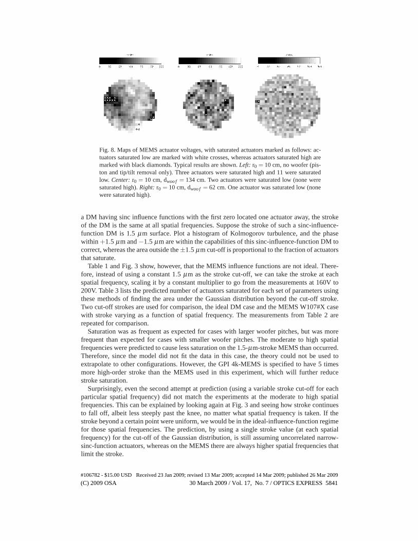
Fig. 8. Maps of MEMS actuator voltages, with saturated actuators marked as follows: ac-tuators saturated low are marked with white crosses, whereas actuators saturated high aremarked with black diamonds. Typical results are shown. Left: r0 = 10 cm, no woofer (pis-ton and tip/tilt removal only). Three actuators were saturated high and 11 were saturatedlow. Center: r0 = 10 cm, dwoo f = 134 cm. Two actuators were saturated low (none weresaturated high). Right: r0 = 10 cm, dwoo f = 62 cm. One actuator was saturated low (nonewere saturated high).
a DM having sinc influence functions with the first zero located one actuator away, the strokeof the DM is the same at all spatial frequencies. Suppose the stroke of such a sinc-influence-function DM is 1.5 μm surface. Plot a histogram of Kolmogorov turbulence, and the phasewithin +1.5 μm and −1.5 μm are within the capabilities of this sinc-influence-function DM tocorrect, whereas the area outside the ±1.5 μm cut-off is proportional to the fraction of actuatorsthat saturate.
Table 1 and Fig. 3 show, however, that the MEMS influence functions are not ideal. There-fore, instead of using a constant 1.5 μm as the stroke cut-off, we can take the stroke at eachspatial frequency, scaling it by a constant multiplier to go from the measurements at 160V to200V. Table 3 lists the predicted number of actuators saturated for each set of parameters usingthese methods of finding the area under the Gaussian distribution beyond the cut-off stroke.Two cut-off strokes are used for comparison, the ideal DM case and the MEMS W107#X casewith stroke varying as a function of spatial frequency. The measurements from Table 2 arerepeated for comparison.
Saturation was as frequent as expected for cases with larger woofer pitches, but was morefrequent than expected for cases with smaller woofer pitches. The moderate to high spatialfrequencies were predicted to cause less saturation on the 1.5-μm-stroke MEMS than occurred.Therefore, since the model did not fit the data in this case, the theory could not be used toextrapolate to other configurations. However, the GPI 4k-MEMS is specified to have 5 timesmore high-order stroke than the MEMS used in this experiment, which will further reducestroke saturation.
Surprisingly, even the second attempt at prediction (using a variable stroke cut-off for eachparticular spatial frequency) did not match the experiments at the moderate to high spatialfrequencies. This can be explained by looking again at Fig. 3 and seeing how stroke continuesto fall off, albeit less steeply past the knee, no matter what spatial frequency is taken. If thestroke beyond a certain point were uniform, we would be in the ideal-influence-function regimefor those spatial frequencies. The prediction, by using a single stroke value (at each spatialfrequency) for the cut-off of the Gaussian distribution, is still assuming uncorrelated narrow-sinc-function actuators, whereas on the MEMS there are always higher spatial frequencies thatlimit the stroke.
#106782 - $15.00 USD Received 23 Jan 2009; revised 13 Mar 2009; accepted 14 Mar 2009; published 26 Mar 2009
(C) 2009 OSA 30 March 2009 / Vol. 17, No. 7 / OPTICS EXPRESS 5841

Fig. 9. Histogram of peak-to-valley (i.e. low-spatial-frequency) stroke measured for allMEMS actuators in the r0 = 15 cm experiment. Dashed line: No woofer (piston and tip/tiltremoval only); Dashed-dotted line: 100-cm-pitch woofer correction; Solid line: 50-cm-pitch woofer correction. The woofer reduces the peak-to-valley stroke on the MEMS by afactor of 3–4.
Fig. 10. Histogram of inter-actuator (i.e. high-spatial-frequency) stroke measured for allMEMS actuators in the r0 = 15 cm experiment. Dashed line: No woofer (piston and tip/tiltremoval only); Dashed-dotted line: 100-cm-pitch woofer correction; Solid line: 50-cm-pitch woofer correction. The woofer reduces the inter-actuator stroke on the MEMS by afactor of 2–3.
#106782 - $15.00 USD Received 23 Jan 2009; revised 13 Mar 2009; accepted 14 Mar 2009; published 26 Mar 2009
(C) 2009 OSA 30 March 2009 / Vol. 17, No. 7 / OPTICS EXPRESS 5842
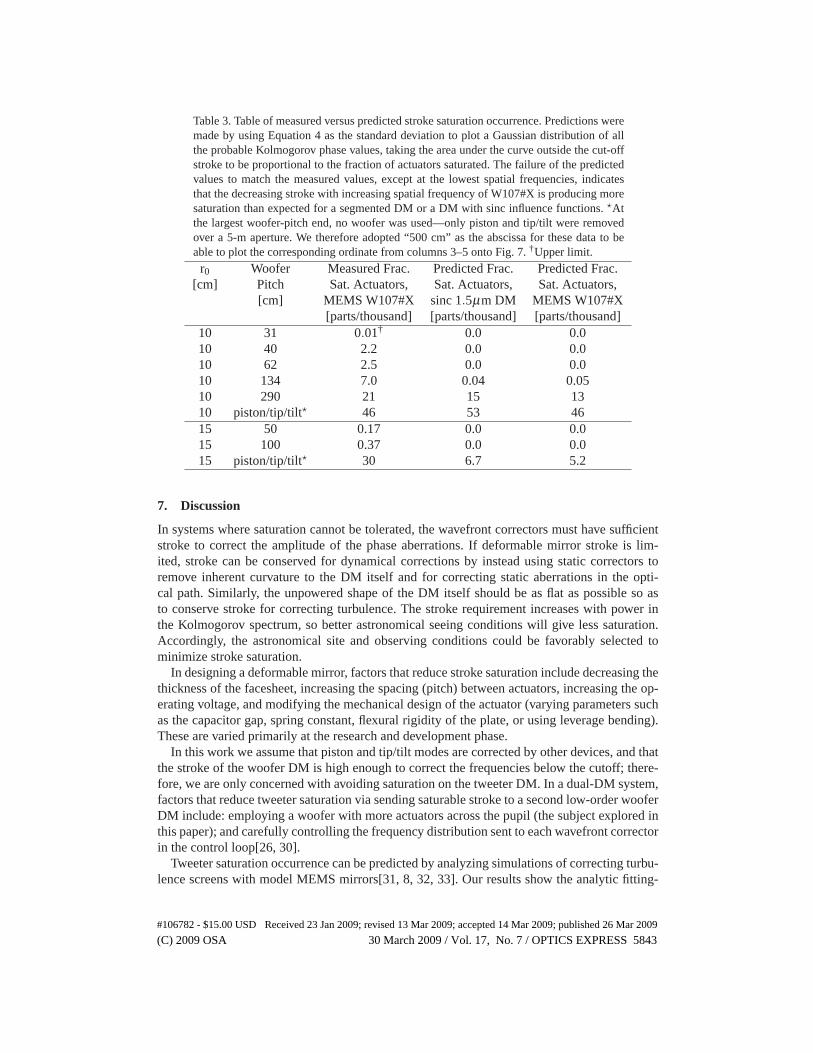
Table 3. Table of measured versus predicted stroke saturation occurrence. Predictions weremade by using Equation 4 as the standard deviation to plot a Gaussian distribution of allthe probable Kolmogorov phase values, taking the area under the curve outside the cut-offstroke to be proportional to the fraction of actuators saturated. The failure of the predictedvalues to match the measured values, except at the lowest spatial frequencies, indicatesthat the decreasing stroke with increasing spatial frequency of W107#X is producing moresaturation than expected for a segmented DM or a DM with sinc influence functions. �Atthe largest woofer-pitch end, no woofer was used—only piston and tip/tilt were removedover a 5-m aperture. We therefore adopted “500 cm” as the abscissa for these data to beable to plot the corresponding ordinate from columns 3–5 onto Fig. 7. †Upper limit.
r0 Woofer Measured Frac. Predicted Frac. Predicted Frac.[cm] Pitch Sat. Actuators, Sat. Actuators, Sat. Actuators,
[cm] MEMS W107#X sinc 1.5μm DM MEMS W107#X[parts/thousand] [parts/thousand] [parts/thousand]
10 31 0.01† 0.0 0.010 40 2.2 0.0 0.010 62 2.5 0.0 0.010 134 7.0 0.04 0.0510 290 21 15 1310 piston/tip/tilt� 46 53 4615 50 0.17 0.0 0.015 100 0.37 0.0 0.015 piston/tip/tilt� 30 6.7 5.2
7. Discussion
In systems where saturation cannot be tolerated, the wavefront correctors must have sufficientstroke to correct the amplitude of the phase aberrations. If deformable mirror stroke is lim-ited, stroke can be conserved for dynamical corrections by instead using static correctors toremove inherent curvature to the DM itself and for correcting static aberrations in the opti-cal path. Similarly, the unpowered shape of the DM itself should be as flat as possible so asto conserve stroke for correcting turbulence. The stroke requirement increases with power inthe Kolmogorov spectrum, so better astronomical seeing conditions will give less saturation.Accordingly, the astronomical site and observing conditions could be favorably selected tominimize stroke saturation.
In designing a deformable mirror, factors that reduce stroke saturation include decreasing thethickness of the facesheet, increasing the spacing (pitch) between actuators, increasing the op-erating voltage, and modifying the mechanical design of the actuator (varying parameters suchas the capacitor gap, spring constant, flexural rigidity of the plate, or using leverage bending).These are varied primarily at the research and development phase.
In this work we assume that piston and tip/tilt modes are corrected by other devices, and thatthe stroke of the woofer DM is high enough to correct the frequencies below the cutoff; there-fore, we are only concerned with avoiding saturation on the tweeter DM. In a dual-DM system,factors that reduce tweeter saturation via sending saturable stroke to a second low-order wooferDM include: employing a woofer with more actuators across the pupil (the subject explored inthis paper); and carefully controlling the frequency distribution sent to each wavefront correctorin the control loop[26, 30].
Tweeter saturation occurrence can be predicted by analyzing simulations of correcting turbu-lence screens with model MEMS mirrors[31, 8, 32, 33]. Our results show the analytic fitting-
#106782 - $15.00 USD Received 23 Jan 2009; revised 13 Mar 2009; accepted 14 Mar 2009; published 26 Mar 2009
(C) 2009 OSA 30 March 2009 / Vol. 17, No. 7 / OPTICS EXPRESS 5843
error model based on the turbulence power spectrum underpredicts incidence of stroke satura-tion. Our original goal in this work was to measure whether stroke saturation would be prob-lematic for GPI. In order to assure the higher-stroke MEMS mirrors (now being fabricated) areadequate for GPI, we plan to measure saturation statistics with similar testing on “engineering-grade” versions of the 4k-MEMS.
8. Conclusions
In this experiment we applied Kolmogorov-turbulence atmospheric phase screens to a MEMSdeformable mirror. The r0 of the phase screens ranged from 10–15 cm, and the pitch of thewoofer used to remove the low spatial frequencies ranged from 8–16 actuators across an 8-mprimary.
The MEMS when solitary suffered saturation ∼4% of the time. Using a woofer DM reducesdramatically the amount of phase sent to the MEMS, and thus mitigated MEMS saturationoccurrence to a fraction of a percent.
The woofer did not mitigate mid-to-high-spatial-frequency stroke as much as expected. Noneighboring actuators were saturated at opposing positions, meaning the most extreme case ofinter-actuator saturation did not occur.
However, moderate to high spatial frequencies did saturate more often than predicted basedon a Gaussian distribution of phase and somewhat-idealized influence functions. This impliesthat correlations in actuators, i.e. high-spatial-frequency stroke limits, are significant. Attemptsto derive the expected saturation using a simple analytical model underpredicted the strokerequirements, showing that empirical studies are important.
Acknowledgments
The authors thank Claire Max, Sandrine Thomas, Andrew Norton, Lisa Poyneer, Jean-PierreVeran, Jean-Francois Lavigne, and our other lab-mates, co-workers, and colleagues for insight-ful discussions that contributed to this work. Furthermore, we thank the anonymous reviewersfor their valuable comments that improved the accuracy, clarity, and scope of the paper. Thiswork was performed under the Michelson Graduate Fellowship for the Jet Propulsion Labora-tory, California Institute of Technology, sponsored by the United States Government under aPrime Contract between the California Institute of Technology and NASA. This research wassupported in part by the National Science Foundation Science and Technology Center for Adap-tive Optics, managed by the University of California at Santa Cruz under cooperative agreementNo. AST-9876783, PI Claire E. Max. Support for this work was also provided by a grant fromthe Gordon and Betty Moore Foundation to the Regents of the University of California, SantaCruz, on behalf of the UCO/Lick Laboratory for Adaptive Optics, directed by Don Gavel. Thecontent of the information does not necessarily reflect the position or the policy of the Gordonand Betty Moore Foundation, and no official endorsement should be inferred. Portions of thiswork were performed under the auspices of the U. S. Department of Energy by the University ofCalifornia, Lawrence Livermore National Laboratory under Contract W-7405-ENG-48. Addi-tionally, support for this work was provided by a minigrant from the Institute of Geophysics andPlanetary Physics through Lawrence Livermore National Laboratory. This research has madeuse of NASA’s Astrophysics Data System Bibliographic Services.
#106782 - $15.00 USD Received 23 Jan 2009; revised 13 Mar 2009; accepted 14 Mar 2009; published 26 Mar 2009
(C) 2009 OSA 30 March 2009 / Vol. 17, No. 7 / OPTICS EXPRESS 5844