striving to make stormwater green pcsm plans common mistakes, notes, etc. presented by aneca y....
TRANSCRIPT

STRIVING TO MAKE STORMWATER GREEN
PCSM PlansCommon Mistakes, Notes, etc.
Presented by
Aneca Y. CrewsPADEP-SERO

2
Agenda
• Common Mistakes
• PCSM Plan Notes
• Stormwater BMP Information Chart 5B

3
Common Mistakes

4
Common Mistakes
• Insufficient infiltration documentation– No testing performed, not enough tests
performed, test field logs not provided, – Unacceptable testing techniques utilized
• Testing not performed at location(s) or elevation(s) of proposed system(s)
• Avoid using the “perc” test• Use infiltration test that determines hydraulic
conductivity.
– No geotechnical information provided– Reduction factors not used

5
Common Mistakes
• Runoff from impervious surfaces are conveyed directly to infiltration systems– Pretreatment should be provided for
stormwater runoff prior to entering a subsurface infiltration system.
• Clogging from sediment and debris→Failure
• Off-Site Discharges– Discharges are not going to well defined
drainage features– Not identified in the Notice Of Intent (NOI)

6
Off site discharge (Section C)
Becoming a common problem.

7
Off Site Discharges– Easements (Legal Issue)
• Fact Sheet• Follow bulleted items
– Analysis of discharge• Discharges to non-surfaces waters
need to demonstrate that the discharge will not cause erosion or damage
– Discharge to Non-Surface Water:
• Level Spreader • Conveyance
Inflow
h
Y
X
Level Spreader
UndisturbedGround
Profile ViewN.T.S.
Plunge Pool
Outflow
Suitable rigid measures and protective geofabric (TRM)- min. 3 ft. or as needed.
Optional Drain. 2” ductile iron Driven horizontally

8
Common Mistake
• Modified Rational Method used for Runoff Volume calculations.
– National Resources Conservation Service (NRCS) methods must be used for Volume calculations.
– The Modified Rational Method is not acceptable.
• Potential Pollutants/Contamination– Not identified on the NOI– Contamination documentation not provided– For Site Specific Standard or Non-residential
Statewide Health Standards proper Erosion and sediment (E&S) not utilized

9
Common Mistake
• Not requesting a Pre-application meeting
– Projects of complex nature or varying from PA Stormwater Best Management Practices (BMP) Manual should request pre-application meeting.
– Conservation District and/or DEP
• Inconsistencies between plans, details, and calculations
– Inconsistent submittals will cause confusion and increase review time.

10
Common Mistakes
• Structural/Non-Structural (NS) BMP Volume Credit– Volume reduction credit can only be taken for
runoff reaching the proposed BMP during the
2-yr 24 hour storm or a smaller event– No more than 25% of required volume
reduction achieved through NS – Can not claim volume credits on Worksheet 5
for extended detention

11
Non Structural Credits from WS 3
Other credits for Non-Struct. BMPs are listed in Chapter 8 of BMP Manual such as:
BMP 5.4.3
Protect/Utilize Natural Flow Paths
Credit = ¼” x Area
BMP 5.6.3 (pt. 2)
Revegetate/Reforest
Credit = 6 cf/tree Deciduous
or
Credit = 10 cf/tree Evergreen

12
Checklist: Criteria and Credits for Non Structural BMPs
Checklists are found in Ch. 8 (Section 8.8)
Checklists are required when
seeking NS Volume Credit
To receive credit, each box
should be checked.

13
NPDES Application (rev. 12/2009)

14
Updated Worksheet 5
NEW OLD

15
Worksheets
• Worksheets 1 thru 5 and 10, should be completed for each point of interest.

16
Nitrates Compliance
• Worksheet 10 can be misleading.
• Only use when can meet Volume Control Guidance (CG-1).– If not, complete WS 11 to 13
• Should control runoff from at least 90% of the disturbed area.– If not, also need WS 12 & 13.– WS 12 – Pollutant Loading– WS 13 – Pollutant Reduction

17
Standard Notes

18
Standard Notes
• Ownership, Operations, and Maintenance Procedures (Must be included on drawings)– Applicant or entity (association, company, agency, etc.)
listed as responsible party
• Provide Quality Control of Materials. As with all BMPs, the final product is only as good as the materials and workmanship that went into it. The designer is encouraged to review and approve materials and workmanship, especially as related to aggregates, geotextiles, soil and topsoil, and vegetative materials.

19
Standard Notes
• Do not compact soil infiltration beds during construction. Prohibit all heavy equipment from the infiltration area and minimize all other traffic. Equipment should be limited to vehicles that will cause the least compaction, such as tracked vehicles.
• Protect the infiltration area from sediment until the surrounding site is completely stabilized. Methods to prevent sediment from washing into BMPs should be clearly shown on plans. Where geo-textile is used as a bed bottom liner, this should be extended several feet beyond the bed and folded over the edge to protect from sediment wash into the bed during construction, and then trimmed. Runoff from construction areas should never be allowed to drain to infiltration BMPs. This can usually be accomplished by diversion berms and immediate vegetative stabilization.
• If an infiltration area is also to be utilized as a temporary sediment basin, excavation should be limited to within 1 foot of the final bottom invert of the infiltration BMP to prevent clogging and compacting the soil horizon, and final grade removed when the contributing site is fully stabilized. All infiltration BMPs should be finalized at the end of the construction process, when upstream soil areas have a dense vegetative cover.
20
PCSM Notes & Permit Special Conditions
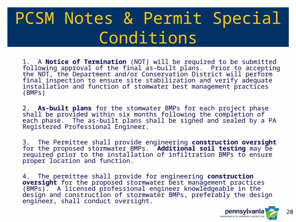
1. A Notice of Termination (NOT) will be required to be submitted following approval of the final as-built plans. Prior to accepting the NOT, the Department and/or Conservation District will perform final inspection to ensure site stabilization and verify adequate installation and function of stomwater best management practices (BMPs)
2. As-built plans for the stomwater BMPs for each project phase shall be provided within six months following the completion of each phase. The as-built plans shall be signed and sealed by a PA Registered Professional Engineer.
3. The Permittee shall provide engineering construction oversight for the proposed stormwater BMPs. Additional soil testing may be required prior to the installation of infiltration BMPs to ensure proper location and function.
4. The permittee shall provide for engineering construction oversight for the proposed stormwater best management practices (BMPs). A licensed professional engineer knowledgeable in the design and construction of stormwater BMPs, preferably the design engineer, shall conduct oversight.

21
STORMWATER BMP INFORMATION CHART 5B

22
Stormwater BMP Info Chart 5.B
• Why is this needed?– A condensing of the calculations for proposed
BMP’s– Highlights common mistakes
• Supporting calculation/documentation should be included in Stormwater Report

23
Stormwater BMP Info Chart 5.B
Measured Infiltration
RateFactor of
Safety
Design Infiltration
RateDewatering
Time*
Elevation Soils, Water
Table, Rock**
Total Drainage Area to BMP
Total Impervious Drainage
Area to BMP
Infiltration BMP
Surface Area
Total Drainage
Area Loading
Ratio
Impervious Area Loading
Ratio
Infil. Elevation
Top of Bed/
Basin***
Infil. Elevation Bottom of
Bed/ Basin***
Elevation Infiltration Test****
Elevation E & S
Sediment Basin
Bottom (if applies)
Volume to be Infiltrated or Permanently removed*****
in./hr. 2 min. in./hr. hrs. sq. ft sq. ft. sq. ft. 8:1 Max 5:1 Max cf
BMP 6.4.1 Pervious Pvmnt w. Infilt. Bed
BMP 6.4.2 Infiltration Basin
BMP 6.4.3 Subsurface Infiltration Bed
BMP 6.4.4 Infiltration Trench
BMP 6.4.5 Rain Garden/Bioretention
BMP 6.4.6 Dry Well / Seepage Pit
BMP 6.4.7 Constructed FilterBMP 6.4.8 Vegetated SwaleBMP 6.4.9 Vegetated Filter StripBMP 6.4.10 Infilt. Berm & Ret. Grading
All information to be based on the 2-year 24-hour storm only.Provide page numbers from the stormwater narrative identifying the location of the above information.* Include active infiltration time, maximum 6 hrs.** Depth to limiting zones must be >2 ft below infiltration testing elevation/proposed infiltration elevation.***If greater than 2 feet of Hydraulic head then a soil scientist justification is required.****Provide supporting field notes/documenation.*****Permanently Removed Volume includes water that is captured and not released. (reused or reduced by evapotranspiration.)
BMP Information
Stormwater BMP Information Chart 5.B 11-20-08
Proposed Infiltration BMP(s) (site specific)
Drainage InformationInfiltration Information

24
Infiltration Information
Measured Infiltration
RateFactor of
Safety
Design Infiltration
RateDewatering
Time*
Elevation Soils, Water
Table, Rock**
Total Drainage Area to BMP
in./hr. 2 min. in./hr. hrs. sq. ft sq. ft. sq. ft. 8:1 Max 5:1 Max cf
BMP 6.4.1 Pervious Pvmnt w. Infilt. Bed
BMP 6.4.2 Infiltration Basin
BMP 6.4.3 Subsurface Infiltration Bed
BMP 6.4.4 Infiltration Trench
BMP 6.4.5 Rain Garden/Bioretention
BMP 6.4.6 Dry Well / Seepage Pit
BMP 6.4.7 Constructed FilterBMP 6.4.8BMP 6.4.9
All information to be based on the 2-year 24-hour storm only.Provide page numbers from the stormwater narrative identifying the location of the above information.* Include active infiltration time, maximum 6 hrs.** Depth to limiting zones must be >2 ft below infiltration testing elevation/proposed infiltration elevation.***If greater than 2 feet of Hydraulic head then a soil scientist justification is required.****Provide supporting field notes/documenation.*****Permanently Removed Volume includes water that is captured and not released. (reused or reduced by evapotranspiration.)
Proposed Infiltration BMP(s) (site specific)
Drainage InformationInfiltration Information

25
Stormwater BMP Info Chart 5.B
Measured Infiltration
RateFactor of
Safety
Design Infiltration
RateDewatering
Time*
Elevation Soils, Water
Table, Rock**
Total Drainage Area to BMP
Total Impervious Drainage
Area to BMP
Infiltration BMP
Surface Area
Total Drainage
Area Loading
Ratio
Impervious Area Loading
Ratio
Infil. Elevation
Top of Bed/
Basin***
Infil. Elevation Bottom of
Bed/ Basin***
Elevation Infiltration Test****
Elevation E & S
Sediment Basin
Bottom (if applies)
Volume to be Infiltrated or Permanently removed*****
in./hr. 2 min. in./hr. hrs. sq. ft sq. ft. sq. ft. 8:1 Max 5:1 Max cf
BMP 6.4.1 Pervious Pvmnt w. Infilt. Bed
BMP 6.4.2 Infiltration Basin
BMP 6.4.3 Subsurface Infiltration Bed
BMP 6.4.4 Infiltration Trench
BMP 6.4.5 Rain Garden/Bioretention
BMP 6.4.6 Dry Well / Seepage Pit
BMP 6.4.7 Constructed FilterBMP 6.4.8 Vegetated SwaleBMP 6.4.9 Vegetated Filter StripBMP 6.4.10 Infilt. Berm & Ret. Grading
All information to be based on the 2-year 24-hour storm only.Provide page numbers from the stormwater narrative identifying the location of the above information.* Include active infiltration time, maximum 6 hrs.** Depth to limiting zones must be >2 ft below infiltration testing elevation/proposed infiltration elevation.***If greater than 2 feet of Hydraulic head then a soil scientist justification is required.****Provide supporting field notes/documenation.*****Permanently Removed Volume includes water that is captured and not released. (reused or reduced by evapotranspiration.)
BMP Information
Stormwater BMP Information Chart 5.B 11-20-08
Proposed Infiltration BMP(s) (site specific)
Drainage InformationInfiltration Information

26
Drainage Information
Elevation Soils, Water
Table, Rock**
Total Drainage Area to BMP
Total Impervious Drainage
Area to BMP
Infiltration BMP
Surface Area
Total Drainage
Area Loading
Ratio
Impervious Area Loading
Ratio
Infil. Elevation
Top of Bed/
Basin***
in./hr. 2 min. in./hr. hrs. sq. ft sq. ft. sq. ft. 8:1 Max 5:1 Max cf
BMP 6.4.1 Pervious Pvmnt w. Infilt. Bed
BMP 6.4.2 Infiltration Basin
BMP 6.4.3 Subsurface Infiltration Bed
BMP 6.4.4 Infiltration Trench
BMP 6.4.5 Rain Garden/Bioretention
BMP 6.4.6 Dry Well / Seepage Pit
BMP 6.4.7 Constructed FilterBMP 6.4.8 Vegetated SwaleBMP 6.4.9 Vegetated Filter StripBMP 6.4.10 Infilt. Berm & Ret. Grading
All information to be based on the 2-year 24-hour storm only.Provide page numbers from the stormwater narrative identifying the location of the above information.* Include active infiltration time, maximum 6 hrs.** Depth to limiting zones must be >2 ft below infiltration testing elevation/proposed infiltration elevation.***If greater than 2 feet of Hydraulic head then a soil scientist justification is required.****Provide supporting field notes/documenation.*****Permanently Removed Volume includes water that is captured and not released. (reused or reduced by evapotranspiration.)
BMP InformationDrainage InformationInfiltration Information

27
Stormwater BMP Info Chart 5.B
Measured Infiltration
RateFactor of
Safety
Design Infiltration
RateDewatering
Time*
Elevation Soils, Water
Table, Rock**
Total Drainage Area to BMP
Total Impervious Drainage
Area to BMP
Infiltration BMP
Surface Area
Total Drainage
Area Loading
Ratio
Impervious Area Loading
Ratio
Infil. Elevation
Top of Bed/
Basin***
Infil. Elevation Bottom of
Bed/ Basin***
Elevation Infiltration Test****
Elevation E & S
Sediment Basin
Bottom (if applies)
Volume to be Infiltrated or Permanently removed*****
in./hr. 2 min. in./hr. hrs. sq. ft sq. ft. sq. ft. 8:1 Max 5:1 Max cf
BMP 6.4.1 Pervious Pvmnt w. Infilt. Bed
BMP 6.4.2 Infiltration Basin
BMP 6.4.3 Subsurface Infiltration Bed
BMP 6.4.4 Infiltration Trench
BMP 6.4.5 Rain Garden/Bioretention
BMP 6.4.6 Dry Well / Seepage Pit
BMP 6.4.7 Constructed FilterBMP 6.4.8 Vegetated SwaleBMP 6.4.9 Vegetated Filter StripBMP 6.4.10 Infilt. Berm & Ret. Grading
All information to be based on the 2-year 24-hour storm only.Provide page numbers from the stormwater narrative identifying the location of the above information.* Include active infiltration time, maximum 6 hrs.** Depth to limiting zones must be >2 ft below infiltration testing elevation/proposed infiltration elevation.***If greater than 2 feet of Hydraulic head then a soil scientist justification is required.****Provide supporting field notes/documenation.*****Permanently Removed Volume includes water that is captured and not released. (reused or reduced by evapotranspiration.)
BMP Information
Stormwater BMP Information Chart 5.B 11-20-08
Proposed Infiltration BMP(s) (site specific)
Drainage InformationInfiltration Information

28
BMP Information
Impervious Area Loading
Ratio
Infil. Elevation
Top of Bed/
Basin***
Infil. Elevation Bottom of
Bed/ Basin***
Elevation Infiltration Test****
Elevation E & S
Sediment Basin
Bottom (if applies)
Volume to be Infiltrated or Permanently removed*****
in./hr. 2 min. in./hr. hrs. sq. ft sq. ft. sq. ft. 8:1 Max 5:1 Max cf
BMP 6.4.1 Pervious Pvmnt w. Infilt. Bed
BMP 6.4.2 Infiltration Basin
BMP 6.4.3 Subsurface Infiltration Bed
BMP 6.4.4 Infiltration Trench
BMP 6.4.5 Rain Garden/Bioretention
BMP 6.4.6 Dry Well / Seepage Pit
BMP 6.4.7 Constructed FilterBMP 6.4.8 Vegetated SwaleBMP 6.4.9 Vegetated Filter StripBMP 6.4.10 Infilt. Berm & Ret. Grading
All information to be based on the 2-year 24-hour storm only.Provide page numbers from the stormwater narrative identifying the location of the above information.* Include active infiltration time, maximum 6 hrs.** Depth to limiting zones must be >2 ft below infiltration testing elevation/proposed infiltration elevation.***If greater than 2 feet of Hydraulic head then a soil scientist justification is required.****Provide supporting field notes/documenation.*****Permanently Removed Volume includes water that is captured and not released. (reused or reduced by evapotranspiration.)
BMP InformationDrainage Information

29
Stormwater BMP Info Chart 5.B
Measured Infiltration
RateFactor of
Safety
Design Infiltration
RateDewatering
Time*
Elevation Soils, Water
Table, Rock**
Total Drainage Area to BMP
Total Impervious Drainage
Area to BMP
Infiltration BMP
Surface Area
Total Drainage
Area Loading
Ratio
Impervious Area Loading
Ratio
Infil. Elevation
Top of Bed/
Basin***
Infil. Elevation Bottom of
Bed/ Basin***
Elevation Infiltration Test****
Elevation E & S
Sediment Basin
Bottom (if applies)
Volume to be Infiltrated or Permanently removed*****
in./hr. 2 min. in./hr. hrs. sq. ft sq. ft. sq. ft. 8:1 Max 5:1 Max cf
BMP 6.4.1 Pervious Pvmnt w. Infilt. Bed
BMP 6.4.2 Infiltration Basin
BMP 6.4.3 Subsurface Infiltration Bed
BMP 6.4.4 Infiltration Trench
BMP 6.4.5 Rain Garden/Bioretention
BMP 6.4.6 Dry Well / Seepage Pit
BMP 6.4.7 Constructed FilterBMP 6.4.8 Vegetated SwaleBMP 6.4.9 Vegetated Filter StripBMP 6.4.10 Infilt. Berm & Ret. Grading
All information to be based on the 2-year 24-hour storm only.Provide page numbers from the stormwater narrative identifying the location of the above information.* Include active infiltration time, maximum 6 hrs.** Depth to limiting zones must be >2 ft below infiltration testing elevation/proposed infiltration elevation.***If greater than 2 feet of Hydraulic head then a soil scientist justification is required.****Provide supporting field notes/documenation.*****Permanently Removed Volume includes water that is captured and not released. (reused or reduced by evapotranspiration.)
BMP Information
Stormwater BMP Information Chart 5.B 11-20-08
Proposed Infiltration BMP(s) (site specific)
Drainage InformationInfiltration Information
•Foot notes reference Appendix C of the PA BMP Manual under Site conditions and constraints and Design consideration

30
2-year 24-hour storm onlySimilar to WS 4 but limited to
drainage to indiv. BMP (Post Dev)

31
Section C – E&S and PCSM
Stormwater BMP Chart 5B should match the summary table in section C.2 of the NPDES application. Both should match Stormwater Report

32
How to expedite the review
• Submit a complete application• Follow the application instructions and BMP Manual.• Provide volume control for difference in 2-year w/o
any voodoo hydrology.• Utilize Worksheets and supporting checklists. (for
each point of interest)• Request a preapplication meeting with CD and/or
DEP.• Communicate with reviewer to better understand
outstanding issues and find viable solution

33
Timeframes* for NPDES Approval:
• Varies among by region and county.• PAG-2:
– 45 to 100 days• Individual Permit:
– 3 to 6 months• Add another 60 days if a public hearing is required.• Each deficiency letter allows 60 days to provide a
complete response
* Timeframes above assume a reasonably quick turnaround by designers to comments.

34
Stormwater BMP Highlights
• Chapter 3- Principles & Control Guidance• Chapter 5- Non-structural BMPs• Chapter 6- Structural BMPs• Chapter 8- Methods & Worksheets• Appendix C – Site Evaluation & Soil testing• NOI checklist & instruction

35
FIN
• Questions?
Contact Info:Aneca Y. Crews
Stormwater Section
PA DEP - SERO
484-250-5129

36
Checklists
• Criteria and Credits for Non-Structural BMPs.– Plan requirements– Required for most
submittals requesting NS Credits.