stripper model for co2 removal from …umpir.ump.edu.my/9046/1/cd8551 @ 67.pdf · iii stripper...
TRANSCRIPT

III
STRIPPER MODEL FOR CO2 REMOVAL FROM
IRON ORE REDUCTION UNIT USING AMINE
SCRUBBING PROCESS
HOE HOI PENG
Thesis submitted in partial fulfilment of the requirements
for the award of the degree of
Bachelor of Chemical Engineering (Pure)
Faculty of Chemical & Natural Resources Engineering
UNIVERSITI MALAYSIA PAHANG
JANUARY 2014
©HOE HOI PENG (2014)

VIII
ABSTRACT
Iron and steel production is a highly energy intensive process which has been
reported to produce about 10% of worldwide CO2 from fossil fuel. Thus, it has become
a potential industry for CO2 removal process. High energy consumption of amine
scrubbing has caused the challenge for the large scale application. Even though recent
studies have been done to reduce the energy consumption, there are lacking of focus on
the optimization of stripper operating conditions. Thus, the objective of this research is
to investigate the relationships of the stripper operating parameters on the reboiler heat
duty and CO2 removal percentage in the stripper. The modeling was done by using rate-
based model in Aspen Plus with “MEA Property Insert” which described a MEA-H2O-
CO2 system thermodynamically with electrolyte-NRTL model. The column
specifications were adapted from a pilot plant in University of Texas, Austin and the
flue gas flow and compositions were adapted from Arasto et al. (2012). From the
results, it showed that the increase in stripper with higher MEA concentration had
reduced the reboiler duty up to 20 % and higher rich solvent temperature were able to
reduce the reboiler heat duty. Besides that, the increase of stripper pressure had
increased CO2 removal efficiency in the stripper yet the CO2 removal percentage was
remained constant with the increase in rich solvent temperature. Lower rich solvent
loadings with constant lean solvent loadings, molar flow rate of CO2 exiting the stripper
and mass flow rate of MEA solvent enabled the reduction in reboiler heat duty. Even
though high stripper temperature enables better performance, the stripper temperature
should be maintained below 125 °C to avoid MEA degradation. Besides that, it is
suggested to use lower lean solvent flow rate so that the output changes can be observed
easily. Based on the results, it can be concluded that the hypotheses were accepted. The
findings of this study are useful as the reference for future amine scrubbing application
on the iron ore reduction unit and to reduce the energy requirement of the process.
Key words: stripper model, iron industry, CO2 removal

IX
ABSTRAK
Pengeluaran besi dan keluli dilaporkan sebagai proses tenaga intensif yang telah
menghasilkan 10% pelepasan carbon dioksida di dunia daripada bahan api. Oleh
demikian, industri tersebut merupakan salah satu industri yang berpotensi dalam proses
penyingkiran carbon dioksida. Proses penyentalan amina memerlukan penggunaan
tenaga yang amat tinggi dan telah mendatangkan cabaran dalam aplikasi berskala besar.
Pelbagai kajian telah dijalankan untuk menggurangkan penggunaan tenaga, namun
pengoptimuman terhadap kondisi stripper masih kurang dijadikan tumpuan kajian. Atas
sebab tersebut, tujuan kajian ini dijalankan adalah untuk menyelidik hubungan antara
parameter operasi stripper terhadap haba pengulang didih dan peratusan penyinkiran
carbon dioksida dalam “stripper”. Pemodelan ini telah dijalani dengan mengunakan
model “rate-based” dalam Aspen Plus dengan “MEA Property Insert” yang
menghuraikan MEA-H2O-CO2 sistem dan elektrolik-NRTL model secare
termodinamik. Ciri-ciri kolum dalam kajian ini beroperasi berasaskan salah satu “pilot
plant” yang bertempat di Universiti Texas, Austin manakala aliran dan komposisi gas
bahan api pula berasaskan kajian Arasto et al. (2012). Hasil kajian menunjukkan
bahawa peningkatan kepekatan MEA dalam stripper telah menurunkan kadar tugas
pengulang didih sebanyak 20% dan peningkatan suhu “rich solvent” pula dapat
menurunkan kadar tugas haba pengulang didih. Selain itu, peningkatan tekanan stripper
telah meninggikan keberkesanan penyingkiran carbon dioksida dalam stripper. Namun
demikian, peratusan penyinkiran carbon dioksida tetap kekal nilainya dengan
peningkatan suhu”rich solvent”. “Rich solvent loadings” yang rendah dengan nilai tetap
untuk “lean solvent loadings”, kadar aliran molar carbon dioksida yang keluar daripada
stripper dan kadar aliran jisim MEA juga akan menurunkan kadar tugas haba pengulang
didih. Walaupun suhu stripper yang tinggi menjamin penyingkiran CO2 secara lebih
efektif tetapi suhu tersebut perlu dikekalkan di bawah 125 °C untuk mengelakkan
degradasi MEA. Penggunaan kadar aliran “lean solvent” yang lebih rendah telah
dicadangkan supaya perubahan output yang lebih jelas dapat diperhatikan. Hipotesis
kajian dikatakan serasi berasaskan hasil kajian yang dikumpul. Hasil tersebut dipercayai
dapat membantu dalam mengurangkan penggunaan tenaga aplikasi proses penyentalan
amina atas unit penghasilan bijih besi.
Kata kunci: model “stripper”, industri besi, penyingkiran CO2

X
TABLE OF CONTENTS
SUPERVISOR‟S DECLARATION ............................................................................... IV
STUDENT‟S DECLARATION ...................................................................................... V
DEDICATION ................................................................................................................. VI
ACKNOWLEDGEMENT ............................................................................................. VII
ABSTRACT ................................................................................................................. VIII
ABSTRAK ...................................................................................................................... IX
TABLE OF CONTENTS ................................................................................................. X
LIST OF FIGURES ........................................................................................................ XI
LIST OF TABLES ....................................................................................................... XIII
LIST OF ABBREVIATIONS ...................................................................................... XIV
LIST OF ABBREVIATIONS ...................................................................................... XVI
1 INTRODUCTION .................................................................................................... 1
1.1 Background ........................................................................................................ 1
1.2 Motivation and problem statement ..................................................................... 3
1.3 Objective ............................................................................................................ 5
1.4 Scope of the research ......................................................................................... 6
1.5 Organisation of this thesis .................................................................................. 7
2 LITERATURE REVIEW ......................................................................................... 8
2.1 Overview ............................................................................................................ 8
2.2 Global warming and CO2 emissions .................................................................. 8
2.3 Iron and steel production .................................................................................. 10
2.4 CO2 capture technology ................................................................................... 13
2.5 Amine scrubbing process ................................................................................. 14
2.6 Limitations of previous researches ................................................................... 16
2.7 Modeling .......................................................................................................... 18
2.8 Thermodynamic and transport properties ........................................................ 19
2.9 Summary .......................................................................................................... 21
3 METHODOLOGY ................................................................................................. 22
3.1 Overview .......................................................................................................... 22
3.2 Assumptions ..................................................................................................... 22
3.3 Electrolyte NRTL model .................................................................................. 22
3.4 Redlich-Kwong-Soave Equation of State (RK-SOAVE EOS) ........................ 26
3.5 Rate-based modeling with ASPEN RateSep .................................................... 27
3.6 Process operating conditions and column specifications ................................. 30
3.7 Mass and energy balance ................................................................................. 31
3.8 Overall regeneration heat duty ......................................................................... 32
3.9 Process operating parameters ........................................................................... 33
3.10 Simulation algorithm .................................................................................... 33
4 RESULTS AND DISCUSSION ............................................................................. 43
4.1 Overview .......................................................................................................... 43
4.2 Model Validation ............................................................................................. 43
4.3 Results and Discussion ..................................................................................... 44
5 CONCLUSION ....................................................................................................... 51
REFRENCES .................................................................................................................. 52
APPENDICES ................................................................................................................ 58

XI
LIST OF FIGURES
Figure 2-1: Annual world greenhouse gas emissions in 2005 according to sectors by
Herzog (2009) ................................................................................................................... 9
Figure 2-2: Global annual average temperature measured over land and oceans by
NCDC (2013) .................................................................................................................. 10
Figure 2-3: Direct CO2 emissions in industry by sector and by region in 2007 by IEA
(2010) .............................................................................................................................. 11
Figure 2-4: China's crude steel production and share of global production (1990–2010)
by Hasanbeigi et al. (2013) ............................................................................................. 11
Figure 2-5: Industrial CO2 emissions reductions from carbon capture and storage
compared to the baseline equivalent scenarios by sector in 2050 by IEA (2010) .......... 12
Figure 2-6: Basic principles of three CO2 capture technologies by Li (2008) ............... 13
Figure 2-7: Energy consumption mix of the steel industry of China in 2004 by Guo and
Fu (2010) ......................................................................................................................... 14
Figure 2-8: Chemical structures of the amines Used in amine scrubbing process for CO2
removal by Shao and Stangeland (2009) ........................................................................ 15
Figure 2-9: Standalone absorber and standalone stripper in amine scrubbing process
adapted from Alie et al., (2004) ...................................................................................... 16
Figure 2-10: Property method models on the physical properties of components by
Aspen Plus® Version 10.2 (2000) .................................................................................. 20
Figure 3-1: ASPEN representation of a stage-based model by Aspen Plus® (2008) ..... 28
Figure 3-2: Simulation algorithm of amine scrubbing process ....................................... 34
Figure 3-3: Property method selection ............................................................................ 35
Figure 3-4: Setup description sheet ................................................................................ 35
Figure 3-5: Standalone absorber ..................................................................................... 36
Figure 3-6: Column specifications of absorber ............................................................... 36
Figure 3-7: Packing rating of absorber ........................................................................... 37
Figure 3-8: Components list of the amine scrubbing process ......................................... 37
Figure 3-9: Chemistry of the equilibrium reactions ........................................................ 38
Figure 3-10: Kinetic reactions of the process ................................................................. 38
Figure 3-11: Flue gas stream specifications ................................................................... 40
Figure 3-12: Lean solvent stream specification .............................................................. 40
Figure 3-13: Standalone stripper ..................................................................................... 41
Figure 3-14: Column specifications of stripper .............................................................. 41
Figure 3-15: Packing rating of stripper ........................................................................... 42
Figure 4-1: Absorber temperature profile for Case 47 (standalone) ............................... 43
Figure 4-2: Stripper temperature profile for Case 47 (standalone) ................................. 44

XII
Figure 4-3: Rich solvent loading versus MEA concentration ......................................... 46
Figure 4-4: Reboiler heat duty versus stripper pressure ................................................. 46
Figure 4-5: Reboiler heat duty versus various rich solvent temperature at 180 kPa ...... 48
Figure 4-6: Specific reboiler duty versus CO2 removal by varying MEA concentration
(Szatkowski, 2009) ......................................................................................................... 49
Figure 4-7: Reboiler heat duty versus rich solvent loading with different stripper
pressures .......................................................................................................................... 49
Figure 4-8: CO2 removal percentage in stripper versus stripper pressure ...................... 50

XIII
LIST OF TABLES
Table 2-1: Comparison of Aspen HYSYS® and Aspen Plus® by Øi, (2007) ............... 18
Table 2-2: Comparison of EOS and Activity Coefficient Models by Aspen Plus® User
Guide Version 12.1 (2005) ............................................................................................. 20
Table 3-1: Constant values of equilibrium constant equations for thermodynamic model
by Freguia (2002) ............................................................................................................ 29
Table 3-2: Rate constants for equation (3.42) by Freguia (2002) ................................... 30
Table 3-3: Flue Gas flow rate and compositions (v%) by Arasto et al. (2012) .............. 30
Table 3-4: Column specifications for amine scrubbing process by Kvamsdal et al.
(2009) and Lawal et al. (2009) ........................................................................................ 31
Table 3-5: Process conditions for rate based pilot plant validation for Case 47 (Dugas,
2006) ............................................................................................................................... 39
Table 4-1: Input conditions for baseline case (Arasto et al., 2012) ................................ 45

XIV
LIST OF ABBREVIATIONS
𝑎𝑜 standard quadratic mixing term
𝑎1 additional, asymmetric term
𝛼𝑖 temperature function by Soave
𝐴𝑗 constant for equation (3.37)
𝐴∅ Debye-Huckel parameter
𝑏 constant in equation (3.19)
𝑏𝑖 constant in equation (3.26)
𝐵𝑗 constant for equation (3.37)
𝐶𝑗 constant for equation (3.37)
𝑑 solvent density
𝐷𝑗 constant for equation (3.37)
𝐷𝑠 dielectric constant of the mixed solvent
𝐷𝑤 dielectric constant for water
E Activation energy
𝑒 charge of an electron
𝑓𝑎𝑐(𝑖) stream scale factor
𝐹 𝑖 mass flow of stream i
𝑔𝑒𝑥 ∗ molar excess Gibbs free energy
𝑔𝑒𝑥 ∗,𝐿𝑅 molar excess Gibbs free energy contribution from long range forces
𝑔𝑒𝑥 ∗,𝑙𝑜𝑐𝑎𝑙 molar excess Gibbs free energy contribution from local forces
𝑔𝑃𝐷𝐻𝑒𝑥 ∗
Pitzer-Debye-Hucel contribution
𝑔𝑒𝑥 ∗,𝐵𝑜𝑟𝑛 Born expression
(𝑖) enthalpy of stream i
𝐻(𝑗) heat flow of heat stream j heat flow of heat stream j
𝐼𝑥 ionic strength on a mole fraction basis
k rate coefficient
𝑘𝐵 Boltzmann constant
kij binary parameters in equation (3.29)
𝐾𝑗 equilibrium constant for thermodynamic model
𝑙𝑖𝑗 binary parameters in equation (3.31)
𝑚𝑖 constant in equation (3.27)
𝑀𝑠 solvent molecular weight in kg/kmol
𝑁𝑜 Avogadro‟s number
NC number of components specified by Comps and Comp-Groups
NH number of combined inlet and outlet heat streams
NM number of combined inlet and outlet material streams
NSS number of sub streams specified
NW number of combined inlet and outlet work streams
𝑃𝑐𝑖 critical pressure of species i
𝑞𝑟𝑒𝑎𝑐𝑡𝑖𝑜𝑛 heat of reaction for desorption of CO2
𝑞𝑟𝑒𝑏𝑜𝑖𝑙𝑒𝑟 reboiler duty
𝑞𝑠𝑒𝑛𝑠𝑖𝑏𝑙𝑒 energy required for sensible heating of the incoming rich amine solution
to the stripper operating temperature.
𝑞𝑠𝑡𝑟𝑖𝑝𝑝𝑒𝑟 energy consumed to generate stripping vapour (steam)
R Universal gas constant
𝑟𝑗 rate of reaction

XV
𝑟𝑘 Born radius of species k
𝑠𝑖𝑔𝑛(𝑖) +1 for inlet streams, -1 for outlet streams in equation (3.43) to (3.46)
𝑠(𝑖, 𝑗) mass fraction of sub stream j in stream i
𝑇 temperature in K
𝑇0 temperature in K in equation (3.42)
𝑇𝑐𝑖 critical temperature of species i
𝑊(𝑘) work of work stream k
Vm molar volume
𝑥𝑘 liquid-phase mole fraction
𝑧(𝑖, 𝑗, 𝑘) mass fraction of component k in sub stream j of stream i
𝑧𝑘 charge on species k
Greek
α non-randomness parameter
ρ closest approach parameter
τ binary energy interaction parameter
𝜔𝑖 acentric factor

XVI
LIST OF ABBREVIATIONS
CCS Carbon capture and storage
DEA Diethanolamine
DGA Diglycolamine
DIPA Di-isopropanolamine
EOS Equation of state model
EU ETS European Union Emission Trading Scheme
GHG Greenhouse gas
GCEP Global Climate and Energy Project
GDP Gross Domestic Product
IEA International Energy Agency
IISI International Iron and Steel Institute
IPAE 2-Isopropylaminoethanol
IPCC Intergovernmental Panel on Climate Change
MDEA Methyldiethanolamine
MEA Monoethanolamine
NBS National Bureau of Statistics
NCDC National Climatic Data Center
NRTL Non-random-two-liquid
OSHA Occupational Safety and Health Administration
PENG-ROB Peng-Robbison
RK-SOAVE Redlich-Kwong-Soave equation

1
1 INTRODUCTION
1.1 Background
It has been known that global warming is one of the most serious environment issues
that pose a threat to the humankind and the living things in this world. Climate change
is negatively affecting the economy, health and communities and the scientists have
concerned that the conditions would be disastrous if no action is taken to control the
situation. One of the initial causes of climate change is the increasing of the CO2
concentration in the atmosphere which leads to the greenhouse effect. Carbon dioxide is
the primary greenhouse gas that contributes the most to climate change because of both
its abundance and long atmospheric lifetime (Simon, 2013).The greenhouse effect is
exerted on the Earth‟s surface which absorption and emission of infrared radiation by
gases in the atmosphere cause the increasing surface temperature of Earth (Kiehl &
Trenberth, 1997).
There are several sources of CO2 emission that are mainly caused by the human
activities such as the generation of electricity and heat, industry processes,
transportation, agriculture and fuel combustion since decades ago. IPCC (2005) has
reported that the using of carbon-based fossil fuel as the primary source of fuel is
expected to be continued for many years from now and the largest source of the global
CO2 emission is due to the burning of fossil fuels. The increase of energy demands due
to the fast economic development in the world has caused the problem to be more
critical. The future CO2 concentration seems to be substantially higher as the rate of
CO2 emission accelerates unless there are significant changes made. One of the methods
that had been proposed was the storage of the pure CO2 stream in a variety of carbon
sink in a long period to reduce or eliminate the accumulation of greenhouse gas in the
atmosphere (GCEP, 2005).
One of the potential CO2 removal industries is iron and steel production since the
production produces a high amount of CO2 gas from the making processes which
includes the fossil fuel power generator and the release of CO2 during the reduction
process from iron ore (Arasto et al., 2012). This statement can be further confirmed by
the report of global steel production sector which has been reported to have maintained

2
an upward trend for the last five years. The production had even reached up to 1058
million tons of crude steel in 2004 (IISI, 2005). Moreover, iron and steel industry is the
largest energy-consuming manufacturing sector in the world which is accounting for 10-
15% of total industrial energy consumption (IEA GHG, 2000). Iron and steel industry is
responsible for 10% of worldwide CO2 emission which is corresponding to 5% of
overall global greenhouse gas emission (IEA, 2008). The increasing trend is predicted
for the amount of CO2 to be produce in this sector since the demand for iron and steel
has rapidly increased in the countries that have been in a primary stage of rapid
economic growth especially in China and India (Simon, 2013).The two most common
steel making processes, Blast Furnace and Basic Oxygen Furnace-based route (BF +
BOF route) and the Electric Arc Furnace route (EAF route) have contributed for about
99% of the global crude steel production (Worldsteel, 2010) and they are the main
sources for the CO2 emission from the iron ore reduction plant. Since coke is used as
reducing agent in the production of iron and steel by using the BF + BOF route which
causes the emission of relatively high CO2 concentration, improvements should be done
in order to reduce the amount of CO2 gas emitted (Arasto et al., 2012).
There are several technologies have been developed to capture carbon dioxide from flue
gas. Movagharnejad and Akbari (2011) has stated that there are numerous techniques
that have been used for the post combustion capture for carbon dioxide from the flue
gases such as chemical absorption, physical absorption, membrane separation and
adsorption. Currently, chemical absorption is the most preferred method for the low
pressure flue gases. According to IEA (2008), amine scrubbing is the post combustion
chemical absorption technique which is the commonly used method to remove CO2
since 1930 which involves the use of various amines such as monoethanolamine
(MEA), diethanolamine (DEA), and methyldiethanolamine (MDEA). The simplest and
most used amine for CO2 removal is MEA (monoethanolamine) which is relatively
inexpensive, low molecular weight, and has a high enthalpy of solution with CO2 which
tends to drive the dissolution process at high rates (GCEP, 2005). Generally, amine
scrubbing has been recognized as one of the potential techniques to solve the climate
change problem by reducing the CO2 emission in large scale (Arasto et al., 2012). This
has brought a possibility to utilize this technology in the iron and steel production
sector. Rochelle (2009) also has suggested amine scrubbing is useful with the steel
works with 25% CO2 and modeling studies by Gielen and Moriguchi (2001) has
3
indicated that CO2 removal might be an attractive strategy for the iron and steel
production sector. However, this removal process has a high consumption of thermal
energy due to the amine regeneration in the stripper and increases the cost of the CO2
removal process.
1.2 Motivation and problem statement
The accelerating rate of the CO2 concentration has concerned the public about the
global warming which leads to serious consequences such as the climate change and the
rising of the average sea level which is expected to be critical by the year 2100 (IPCC,
2005). In addition, a further global warming of minimally 1.8 to 4°C in this century and
at the worst case of 6.4°C is expected. This can be avoided if the people around the
world decrease the greenhouse gas (GHG) emissions. Iron and steel industry has proven
to be one of the largest sources of CO2 which contribute 10% of worldwide CO2
emission and 5% of overall global greenhouse gas emission (IEA, 2008). Consequently,
the application of the CO2 removal system should be done in this industry as one of the
practical ways to reduce the global CO2 emission effectively to avoid the conditions to
be worsened.
Amine scrubbing process which involves the removal of carbon dioxide is a technically
feasible method of making effective and continuous reductions of CO2 emissions. This
can be done by reducing the CO2 concentration in the atmosphere to a controllable level
and focus on the increase of the efficiency of energy conversion and/or utilization in the
amine scrubbing plant by substituting the current fossil fuel power generators to
renewable sources of energy (Li, 2008). The main advantage of amine scrubbing is it
can be installed to the existing power plants without major modifications (Arachchige et
al., 2012). As mentioned by Alie et al. (2004), amine scrubbing process consists of an
absorber and a stripper as the main unit operations which are important for CO2
removal. Stripper is especially important in this process to regenerate the amine solvent
so that the CO2 removal percentage is kept in high values. Many researchers have done
the studies on the amine scrubbing process but the studies mainly focused on chemical
reaction mechanism, mass transfer, gas/liquid equilibrium, and other related aspects of
CO2 absorption (Aroonwilas et al., 1999; Soave & Feliu, 2002; Freguia & Rochelle,
2003). However, the most challenging issue is the large quantities of energy required to
regenerate the amine solvent within the CO2 capture process. Large amount of energy is

4
needed especially in the stripper‟s reboiler and CO2 compression which is higher than
the capital cost. This cost of implementation is too high to be applied in the large scale
industry and many researchers start to focus on the design of amine scrubbing units
which are mainly consisting of absorber, stripper and heat exchanger in order to reduce
the energy consumption and the cost of the process. By varying the stripper parameters
in this process, the performance and the cost are highly affected in the system. Thus,
stripper operating parameters have been labelled as the primary factors for the energy
reducing in the amine scrubbing system.
Recent studies have been done in many aspects in order to reduce the energy
consumption of amine scrubbing process. However, there are limitations such as
insufficient comparisons between the parameters involved in the studies especially in
the iron and steel industry. There are a lot of attentions are paid to the power plants but
less in the iron and steel industry. The studies have been done are based on the case
study in the steel mills that currently exist around the world such as in Finland (Arasto
et al., 2012). Arasto et al. (2012) had focused on only three different heat production
scenarios and the amount of CO2 can be captured based on these three scenarios and the
best amine solvent has been evaluated by comparing the CO2 removal percentage of
each solution. Goto et al. (2012) has only investigated on the types of absorbent that can
result the highest CO2 absorption rate based on the pilot plant scale experimental
method in Japan with 2-Isopropylaminoethanol (IPAE) aqueous solution. Cheng et al.
(2010) also has used the pilot plant scale experimental method to investigate the CO2
removal percentage by using more parameters such as types of solvent, the speed of the
rotation of rotating packed bed column for absorber, temperature, gas flow rate and the
liquid flow rate for solvent in the rotating packed bed.
The introduction of innovative configurations of stripper (Van Wagener & Rochelle,
2011) might increase the operating cost of the CO2 removal since the unit operations
involved would be increased even though the introduction of more complexity to the
process flow by means of splits, recycles, and multiple pressure stages can reduce the
existing driving forces to cut down on total energy loss. According to Van Wagener and
Rochelle (2011), the reduction of the driving forces and the total compressor work can
be done by introducing the more complex configurations with compressor by collecting
high-pressure CO2.

5
On the other hand, the invention of the new solvents and additives which are added into
the amine solution in order to fasten the reaction kinetics are still in research and
development progress (Cullinane & Rochelle, 2004) such as the potassium
carbonate/piperazine solvent. Even though it has been proven that this solvent can
ensure very high CO2 absorption rate without limiting the lean solvent loading in 0.40
mol CO2/mol solvent but the price is much higher compared to MEA and the stability of
the solvent is still under investigation.
There are limited studies by previous researchers focused on the effects of stripper
operating parameters on the energy consumption reduction in the CO2 removal process.
Hence, this study aimed to investigate the effects of stripper operating parameters such
as the rich solvent loading (mol CO2/mol MEA), CO2 removal percentage, MEA
concentration, reboiler heat duty, stripper operating pressure and rich solvent
temperature on the energy consumption of the CO2 removal process which is directly
affecting the operation cost. The optimization of these parameters not only can reduce
the energy consumption and investment costs but it also can ensure the secure operation
safety.
The most precise way to study the effects of the stripper parameters is via experiments.
However, there are some critical issues regarding experimental procedures since amine
scrubbing covers a large range of operating conditions from normal atmosphere with
supercritical state, and involve multi-component mixtures (Li, 2008). Besides that,
MEA solvent is also hazardous to the human body and overexposed to this amine
solution would possibly cause the irritation of the respiratory system and excretory
system (OSHA, 2013). Moreover, for research purposes, a large scale of CO2 capture
plant is very expensive to build and time consuming. Consequently, process simulation
and modeling play an important role in process optimization and in evaluation of the
various process alternatives. In this research, Aspen Plus® will be used as the
simulation tool to develop the model.
1.3 Objective
This study aims to investigate the influence of stripper operating parameters on the
overall energy consumption of CO2 removal from iron ore reduction unit by amine

6
scrubbing process which is directly affecting the cost of operation by using Aspen
Plus®.
1.4 Scope of the research
The following are the scopes of this study:
Modeling of stripper for CO2 removal for an iron ore reduction unit using amine
scrubbing process based on the case study on Ruukki Metals Ltd.‟s Raahe steel
mill which was done by Arasto et al. (2012).
Modeling analysis of stripper operating parameters on the energy consumption
of the amine scrubbing process.
First of all, the process flow diagram for amine scrubbing was modified by referring to
Harun et al. (2012) and the flue gas flow rate and composition are adapted from the
Arasto et al. (2012) based on the case study on Ruukki Metals Ltd.‟s Raahe steel mill.
The thermodynamic and transport properties are modeled by using „„MEA Property
Insert‟‟ (Abu-Zahra et al., 2006). Then, the identification of all the parameters, physical
properties, column specifications and constants is done. In this study, the stripper
operating parameters such as rich solvent loading (mol CO2/mol MEA), rich solvent
temperature and stripper operating pressure are set as the input variables while the
performance indicators are including reboiler heat duty and CO2 removal percentage in
the stripper which are proven to be important leads to a significant cost due to energy
consumption. The mass balance and energy balance are calculated based on the
formulas stated in Chapter 3. All the data are inserted into the system and the baseline
case simulation is run as the standard for further comparisons among the variables. The
baseline case is defined by using the standalone absorber and a variation of the pure
MEA solvent flow rate of 30 wt. % to determine the amount of CO2 being absorbed and
the column specifications are shown in Chapter 3 which is referred to the pilot plant
from University of Texas that is validated by Kvamsdal et al. (2009) and Lawal et al.
(2009). After the simulation is done, the analysis on the performance is done based on
the results and comparison is carried out with the previous studies.
Several hypotheses are made in this study. First, the thermal energy requirement for
reboiler decreases with increasing rich solvent loading and the increase in CO2 removal
percentage would increase the energy consumption. It is also expected that a significant

7
amount of energy can be saved by increasing the MEA concentration in the
absorber/stripper but the high MEA concentrations may cause corrosion in the
absorber/stripper and solvent degradation. Besides that, the increase of stripper pressure
is expected to cause a higher efficiency of the amine regeneration and would reduce
energy consumption.
1.5 Organisation of this thesis
The structure of the reminder of the thesis is outlined as follows:
Chapter 2 provides a description of the problems, background, and applications of
amine scrubbing process for CO2 removal in iron and steel industry. Besides that,
general descriptions of the characteristics of the technique, as well as the theories that
are related for the modeling are presented. This chapter also provides a brief discussion
of the studies available for the simulation, mentioning their applications and limitations
for energy consumption reduction analysis. A summary of the previous study on amine
scrubbing as well as in other fields such as CO2 removal in the power plant is also
presented.
Chapter 3 gives a review of the procedures and detailed property model with the theory
that are applied for the modeling of amine scrubbing process for CO2 removal. All the
correlation, formulas and equations that are applied in this modeling are stated and
explained accordingly. Justifications are stated to clarify the reasons of the usage. A
standalone absorber is used as a baseline case to obtain the parameters needed to
complete the whole process modeling and the description of a complete process flow
diagram of the amine scrubbing is supported with the figures.
Chapter 4 shows the result and it is discussed accordingly based on the data used and
the results obtained.
Chapter 5 concludes the result and discussion which had obtained from the simulation
and recommendations are given based on the result and discussion made.

8
2 LITERATURE REVIEW
2.1 Overview
In this chapter, the problems and motivations that lead to the development of CO2
removal by using amine scrubbing process are clearly discussed. Then, the explanation
is done to justify the application of this technology should be done in iron and steel
industry and a summary of the limitations based on references from past studies is
stated and discussed. Modeling is the best way to analyse the influence of stripper
conditions on energy consumption of the amine regeneration and the properties of the
modeling are explained at the end of this chapter.
2.2 Global warming and CO2 emissions
The growth in the world gross domestic product (GDP) was the main contributor to the
recent increase in CO2 emissions (Raupach et al., 2007) and it is directly affecting the
rising of global surface temperature significantly for the past decades. This condition
has become even more pronounced in recent decades. Human activities such as fossil
fuel burning, waste gas emission from the industries and deforestation are the main
sources of greenhouse gases, especially carbon dioxide which acts as a primary
greenhouse gas that contributes the most to climate change (Simon, 2013). The increase
of energy demands due to the fast economic development in the world has caused the
problem to be more critical as the rate of CO2 emission accelerates, hence, the
authorities, engineers and scientists are working hard to solve this international problem
without affecting the current investments. Figure 2.1 shows the annual world
greenhouse gas emissions in 2005 according to sectors. The CO2 emissions are
measured as a percentage of total world carbon dioxide equivalent emissions (Herzog,
2009).

9
Figure 2-1: Annual world greenhouse gas emissions in 2005 according to sectors by
Herzog (2009)
Based on Figure 2-1, the CO2 emission is highly depending on the electricity and heat
generation with the fuels which is 24.9% of overall global greenhouse gas emission.
Besides that, industry and transportation are also the important contributors to the high
concentration of CO2 in the atmosphere. Both of them have made up of 14.7% and
14.3% respectively. This has meant that industry is also one of the focus points to
stabilize the global CO2 concentration.
According to IPCC (2007), global warming has been detected in natural systems such as
sea level rise and critical increase in Earth‟s surface temperature. Besides that, hundreds
of millions of people are affected by flooding, low water supplies, increased
malnutrition and increased health issues due to the climate change. Moreover, it has
caused a huge impact to the extinction of many species and reduced diversity of
ecosystems (Schneider et al., 2007). It was proven by the researchers that warming
above 3 °C could reduce the crop yields and lead to a reduction in global food
production. Figure 2-2 shows the global annual average temperature measured over land
and oceans.

10
Figure 2-2: Global annual average temperature measured over land and oceans by
NCDC (2013)
Red bars indicate temperatures above and blue bars indicate temperatures below the
1901-2000 average temperature. The black line shows atmospheric carbon dioxide
concentration in parts per million. Based on this graph, the global average temperature
shows an increase of approximately 1.4°F since the early 20th century. The data were
collected based on the air temperature data over land and sea-surface temperatures
observed from ships, buoys and satellites. Even though the graph does not show a
continuously increasing trend for every year but it is clear that this is a long-term global
warming trend. The fluctuations in temperature for several years are due to natural
processes, such as the effects of El Ninos, La Ninas, and the eruption of large
volcanoes. According to the graph, 20 warmest years have all occurred since 1981, and
the 10 warmest have all occurred in the past 12 years (NCDC, 2013).
2.3 Iron and steel production
The industrial activities which involve the large primary material industries such as
chemicals and petrochemicals, iron and steel, cement, pulp and paper, and aluminium
have supplied most of the CO2 in the atmosphere although some of these industries have
produced less CO2 from the improvements in energy efficiency and material flow
management. However, the demand for industrial products is expected to double or
triple over the next 40 years. Thus, they would become the main CO2 emissions sources
in the future.
11
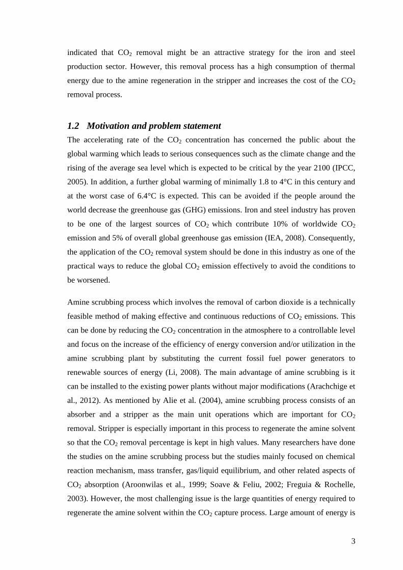
Figure 2-3: Direct CO2 emissions in industry by sector and by region in 2007 by IEA
(2010)
Based on Figure 2-3, iron and steel, cement and chemicals had accounted for almost
three-quarters of CO2 emissions in industry in 2007 and China is the world largest CO2
emission country in that particular year. According to Farla et al. (1995), iron and steel
production is a highly energy intensive process which can produce up to 20 million tons
of CO2 annually. This phenomenon is estimated to be more critical in the following
years since the demands for steel have rapidly increased in the countries that have been
in a primary stage of rapid economic growth especially in China and India (Simon,
2013). Gielen (2003) also stated that the development of iron and steel industry has
provided the largest point source of energy related CO2 emissions in the world and
makes it as one of the largest potential CO2 removal industry.
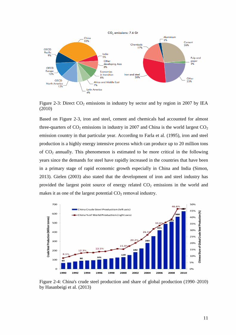
Figure 2-4: China's crude steel production and share of global production (1990–2010)
by Hasanbeigi et al. (2013)

12
Figure 2-4 has shown that the China's crude steel production has increased significantly
from the pass 10 years and it is predicted to continue the trends for the coming decades.
Starting in the 1990s, the industry development has accelerated and exceeding more
than 100 million metric tons (Mt) in 1996. After that, steel production in China has
continued to increase rapidly and it makes China to become the world's largest crude
steel producer for 14 continuous years. Furthermore, Worldsteel (2011) and NBS (2012)
have stated that the average annual growth rate of crude steel production in China was
18.5% between 2000 and 2009. In 2010, the iron and steel production in China had
consumed around 461 TWh of electricity and 14,872 PJ of fuel which represented
46.6% of the world steel production in that year. Guo and Fu (2010) has also reported
that the three main emission sources in the processes of iron and steel production which
are direct on-site burning of fossil fuels, indirect emission from electricity consumed
during the production process and direct non-energy related emissions are the CO2
emission sources and the first and second sources are the main cause of CO2 discharges.
During the reduction process of iron production, large amount of carbon dioxide gas
(CO2) is produced and causes the iron production less productive and low in quality.
Consequently, the capture and removal of the gas has become the excellent solution to
improve the quality and yield of products by eliminating the contaminants and thus,
reducing coal and coke consumptions and the emissions of CO2 to the atmosphere
(IPCC, 2005). Gielen (2003) also has reported that the capture technology will help the
iron production sector to reduce up to 4% of the global CO2 emissions. However, the
number and impact of competing strategies for the removal of CO2 in the iron and steel
production are relatively low compared to the electricity sector such as power plants.
Figure 2-5: Industrial CO2 emissions reductions from carbon capture and storage
compared to the baseline equivalent scenarios by sector in 2050 by IEA (2010)

13
Figure 2-5 has shown the emissions reductions comparison between 1.7 Gt CO2 and 2.5
Gt CO2 need to be achieved through the application of carbon capture and storage
(CCS) in industry in the BLUE low-demand and high demand scenarios respectively.
From the data, it is expected that there are important CO2 reduction opportunities for
carbon dioxide gas removal in the iron and steel (IEA, 2010) where it showed high
percentage values for both of the scenarios.
2.4 CO2 capture technology
There are three types of main approaches to separate the CO2 generated from a primary
fossil fuel such as coal, natural gas or oil, biomass, or mixtures of these fuels. These
technologies are post-combustion capture, pre-combustion capture, and oxy-fuel
combustion capture. According to IEA (2010), all of these options have resulted in a
significant energy penalty to the base plant and it is expected that the energy
requirement can be reduced through continuous researches and experimental studies.
Figure 2-6: Basic principles of three CO2 capture technologies by Li (2008)
Post-combustion capture is a process that separates CO2 from combustion
products such as nitrogen, oxygen and water. The capture can occur anywhere
along the product processing stream from the combustor to effluent exhaust
which the flue gas is produced after the combustion of the fuel.

14
Pre-combustion is a process of the separation of carbon in the form of CO2 from
a resource after the energy content of the resource is transferred to a carbon-free
energy carrier. The most common configuration involves gasification with air or
oxygen. The products undergo a water-gas shift to a high concentration stream
of CO2 and H2. The CO2 is then captured and the H2 is reacted with air.
Oxy-fuel combustion is the separation of oxygen from nitrogen in the air to
produce a nitrogen-free oxidizer stream. During this process, reaction with fuel
is occurred to produce a stream composed primarily of CO2, oxygen, and water.
The water can then be removed through phase separation.
Figure 2-7 has shown the energy consumption according to the source of the steel
industry of China in 2004 and coal is the main fossil fuel which can produce large
amount of CO2 through combustion is used to generate the heat for the process. Hence,
post-combustion capture is applicable in this industry to separate CO2 from combustion
products.
Figure 2-7: Energy consumption mix of the steel industry of China in 2004 by Guo and
Fu (2010)
2.5 Amine scrubbing process
There are several CO2 separation technologies for post-combustion CO2 capture and
chemical absorption is the most developed and preferred technique to capture CO2 from
flue gas (Mofarahi et al., 2008). This chemical absorption process is adapted from the
gas processing industry where amine-based processes have been used commercially for
the removal of acid gas impurities from process gas streams (GCEP, 2005). Amine
based CO2 capture is well known for many industries such as oil and gas industry and
food industry where CO2 is captured from flue gas and used in several products (Shao &