striper specifications - missouri department of transportation buyers web page/documents... · 1 of...
TRANSCRIPT

1 of 74
MISSOURI DEPARTMENT OF TRANSPORTATION
GENERAL SERVICES DIVISION
SPECIFICATIONS FOR
60,000 LB. GVWR
TANDEM AXLE TRUCK MOUNTED TRAFFIC LINE STRIPER
November 28, 2016
2 of 74
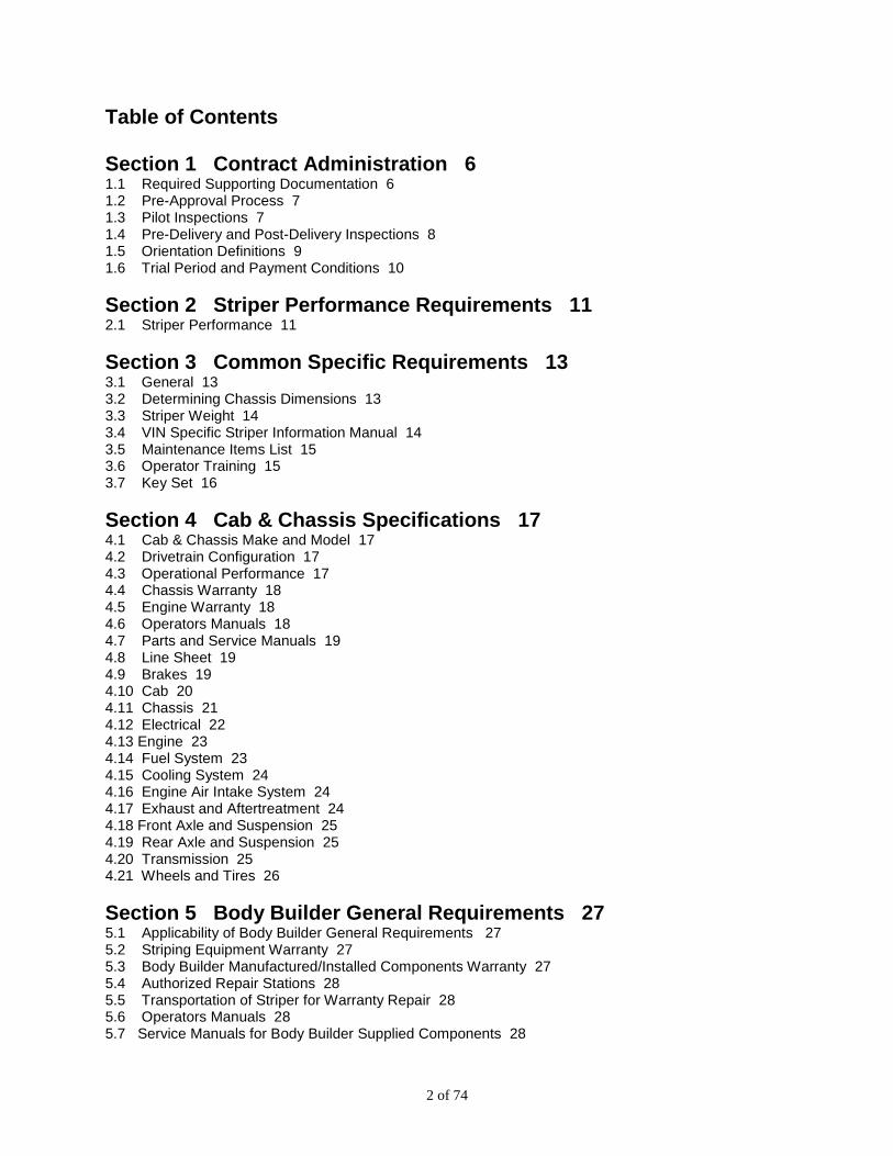
Table of Contents Section 1 Contract Administration 6 1.1 Required Supporting Documentation 6 1.2 Pre-Approval Process 7 1.3 Pilot Inspections 7 1.4 Pre-Delivery and Post-Delivery Inspections 8 1.5 Orientation Definitions 9 1.6 Trial Period and Payment Conditions 10
Section 2 Striper Performance Requirements 11 2.1 Striper Performance 11
Section 3 Common Specific Requirements 13 3.1 General 13 3.2 Determining Chassis Dimensions 13 3.3 Striper Weight 14 3.4 VIN Specific Striper Information Manual 14 3.5 Maintenance Items List 15 3.6 Operator Training 15 3.7 Key Set 16
Section 4 Cab & Chassis Specifications 17 4.1 Cab & Chassis Make and Model 17 4.2 Drivetrain Configuration 17 4.3 Operational Performance 17 4.4 Chassis Warranty 18 4.5 Engine Warranty 18 4.6 Operators Manuals 18 4.7 Parts and Service Manuals 19 4.8 Line Sheet 19 4.9 Brakes 19 4.10 Cab 20 4.11 Chassis 21 4.12 Electrical 22 4.13 Engine 23 4.14 Fuel System 23 4.15 Cooling System 24 4.16 Engine Air Intake System 24 4.17 Exhaust and Aftertreatment 24 4.18 Front Axle and Suspension 25 4.19 Rear Axle and Suspension 25 4.20 Transmission 25 4.21 Wheels and Tires 26
Section 5 Body Builder General Requirements 27 5.1 Applicability of Body Builder General Requirements 27 5.2 Striping Equipment Warranty 27 5.3 Body Builder Manufactured/Installed Components Warranty 27 5.4 Authorized Repair Stations 28 5.5 Transportation of Striper for Warranty Repair 28 5.6 Operators Manuals 28 5.7 Service Manuals for Body Builder Supplied Components 28

3 of 74
5.8 Paint and Finish 29 5.9 Body Builder Installed Threaded Fasteners 29 5.10 Body Builder Installed Electrical and Wiring 30 5.11 Body Builder Installed Air Powered Accessory Installation 31 5.12 Body Builder Installed Hydraulic Powered Accessory Installation 32 5.13 Chemical Resistance 32 5.14 Stainless Steel 32 5.15 Body Builder Installed Grease Zerks and Remote Grease Lines 32 5.16 Conspicuity Tape 33 5.17 Striper Weight Identification Tag 33
Section 6 Aluminum Platform 34 6.1 Platform General Requirements 34 6.2 Platform Specific Requirements 34
Section 7 APU, Compressed Air and Hydraulic Systems 36 7.1 Auxiliary Power Unit General Requirements 36 7.2 APU Operational Performance 36 7.3 APU Warranty 37 7.4 Engine Warranty 37 7.5 Operators Manuals 37 7.6 Engine 38 7.7 Compressed Air System 38 7.8 Hydraulic System 40
Section 8 Paint System 42 8.1 Paint System Operational Performance 42 8.2 Paint System General Requirements 42 8.3 White and Yellow Paint Tank 43 8.4 Black Paint Tank 44 8.5 Low Pressure Paint Transfer Pumps 45 8.6 Paint System Plumbing 45 8.7 Paint Heating System 49 8.8 Hydraulic High Pressure Paint Pumps 50 8.9 Paint Guns 50
Section 9 Bead System 52 9.1 Bead System Operational Performance 52 9.2 Bead Storage Tank 52 9.3 Bead Storage Tank Scale 52 9.4 Bead Storage Tank Air Supply 52 9.5 Bead System Plumbing 53 9.6 Bead Loading System 53 9.7 Bead Guns 54
Section 10 Spray Gun Carriages 55 10.1 Spray Gun Carriage General Requirements 55 10.2 Spray Gun Carriage Specific Requirements 55
Section 11 Rear Operators Cab 57 11.1 Cab Structure 57 11.2 Rear Steps 57 11.3 Doors 57
4 of 74
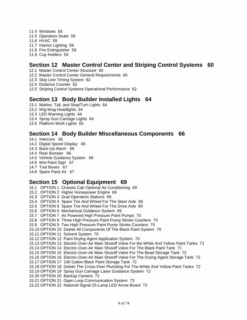
11.4 Windows 58 11.5 Operators Seats 59 11.6 HVAC 59 11.7 Interior Lighting 59 11.8 Fire Extinguisher 59 11.9 Cup Holders 59
Section 12 Master Control Center and Striping Control Systems 60 12.1 Master Control Center Structure 60 12.2 Master Control Center General Requirements 60 12.3 Skip Line Timing System 62 12.4 Distance Counter 62 12.5 Striping Control Systems Operational Performance 62
Section 13 Body Builder Installed Lights 64 13.1 Marker, Tail, and Stop/Turn Lights 64 13.2 Wig-Wag Headlights 64 13.3 LED Warning Lights 64 13.4 Spray Gun Carriage Lights 64 13.5 Platform Work Lights 65
Section 14 Body Builder Miscellaneous Components 66 14.1 Intercom 66 14.2 Digital Speed Display 66 14.3 Back-Up Alarm 66 14.4 Rear Bumper 66 14.5 Vehicle Guidance System 66 14.6 Wet Paint Sign 67 14.7 Tool Boxes 67 14.8 Spare Parts Kit 67
Section 15 Optional Equipment 69 15.1 OPTION 1 Chassis Cab Optional Air Conditioning 69 15.2 OPTION 2 Higher Horsepower Engine 69 15.3 OPTION 3 Dual Operators Stations 69 15.4 OPTION 4 Spare Tire And Wheel For The Steer Axle 69 15.5 OPTION 5 Spare Tire And Wheel For The Drive Axle 69 15.6 OPTION 6 Mechanical Guidance System 69 15.7 OPTION 7 Air Powered High Pressure Paint Pumps 70 15.8 OPTION 8 Three High Pressure Paint Pump Stroke Counters 70 15.9 OPTION 9 Two High Pressure Paint Pump Stroke Counters 70 15.10 OPTION 10 Delete All Components Of The Black Paint System 70 15.11 OPTION 11 Solvent System 70 15.12 OPTION 12 Paint Drying Agent Application System 70 15.13 OPTION 13 Electric-Over-Air Main Shutoff Valve For the White And Yellow Paint Tanks 71 15.14 OPTION 14 Electric-Over-Air Main Shutoff Valve For The Black Paint Tank 71 15.15 OPTION 15 Electric-Over-Air Main Shutoff Valve For The Bead Storage Tank 72 15.16 OPTION 16 Electric-Over-Air Main Shutoff Valve For The Drying Agent Storage Tank 72 15.17 OPTION 17 100 Gallon Black Paint Storage Tank 72 15.18 OPTION 18 Delete The Cross-Over Plumbing For The White And Yellow Paint Tanks 72 15.19 OPTION 19 Spray Gun Carriage Laser Guidance System 72 15.20 OPTION 20 Backup Camera 72 15.21 OPTION 21 Open Loop Communication System 73 15.22 OPTION 22 National Signal 25-Lamp LED Arrow Board 73

5 of 74
15.23 OPTION 23 Transport Of Striper At Time Of Delivery 73 15.24 OPTION 24 Travel Expense Per Body Builder Training Session At MoDOT Striper Location 73 15.25 OPTION 25 Per Day Training Expense For Body Builder Training Session At MoDOT Striper Location 73 15.26 OPTION 26 Travel Expense Per Technical Training Session At MoDOT Striper Location 73 15.27 OPTION 27 Per Day Training Expense For Technical Training Session At MoDOT Striper Location 74
6 of 74
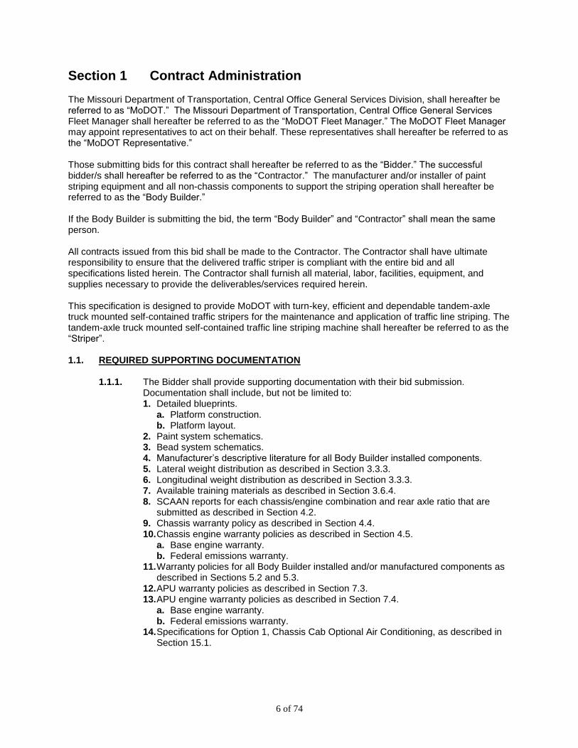
Section 1 Contract Administration The Missouri Department of Transportation, Central Office General Services Division, shall hereafter be referred to as “MoDOT.” The Missouri Department of Transportation, Central Office General Services Fleet Manager shall hereafter be referred to as the “MoDOT Fleet Manager.” The MoDOT Fleet Manager may appoint representatives to act on their behalf. These representatives shall hereafter be referred to as the “MoDOT Representative.” Those submitting bids for this contract shall hereafter be referred to as the “Bidder.” The successful bidder/s shall hereafter be referred to as the “Contractor.” The manufacturer and/or installer of paint striping equipment and all non-chassis components to support the striping operation shall hereafter be referred to as the “Body Builder.” If the Body Builder is submitting the bid, the term “Body Builder” and “Contractor” shall mean the same person. All contracts issued from this bid shall be made to the Contractor. The Contractor shall have ultimate responsibility to ensure that the delivered traffic striper is compliant with the entire bid and all specifications listed herein. The Contractor shall furnish all material, labor, facilities, equipment, and supplies necessary to provide the deliverables/services required herein. This specification is designed to provide MoDOT with turn-key, efficient and dependable tandem-axle truck mounted self-contained traffic stripers for the maintenance and application of traffic line striping. The tandem-axle truck mounted self-contained traffic line striping machine shall hereafter be referred to as the “Striper”. 1.1. REQUIRED SUPPORTING DOCUMENTATION
1.1.1. The Bidder shall provide supporting documentation with their bid submission. Documentation shall include, but not be limited to: 1. Detailed blueprints.
a. Platform construction. b. Platform layout.
2. Paint system schematics. 3. Bead system schematics. 4. Manufacturer’s descriptive literature for all Body Builder installed components. 5. Lateral weight distribution as described in Section 3.3.3. 6. Longitudinal weight distribution as described in Section 3.3.3. 7. Available training materials as described in Section 3.6.4. 8. SCAAN reports for each chassis/engine combination and rear axle ratio that are
submitted as described in Section 4.2. 9. Chassis warranty policy as described in Section 4.4. 10. Chassis engine warranty policies as described in Section 4.5.
a. Base engine warranty. b. Federal emissions warranty.
11. Warranty policies for all Body Builder installed and/or manufactured components as described in Sections 5.2 and 5.3.
12. APU warranty policies as described in Section 7.3. 13. APU engine warranty policies as described in Section 7.4.
a. Base engine warranty. b. Federal emissions warranty.
14. Specifications for Option 1, Chassis Cab Optional Air Conditioning, as described in Section 15.1.

7 of 74
1.2. PRE-APPROVAL PROCESS
1.2.1. Any notation throughout the following specification that states “pre-approved” requires the Bidder to submit a request for acceptance of the item/s for approval by the date listed in the bid documents. 1. Requests shall be submitted to the MoDOT Fleet Manager at the address listed in
the bid documents. 2. Requests may be in the form of a printed paper copy or email.
a. Bidder is responsible to ensure receipt of the request. 3. Requests shall include supporting documentation for each item submitted.
a. Items not accompanied by supporting documentation shall not be approved. 4. Items that shall require pre-approval include:
a. APU make and model as described in Section 7.1.1. 1. Air compressor make, model, and displacement. 2. Hydraulic pump make, model, and displacement.
5. Items that may require pre-approval for equivalency include: a. Electrically operated air valves other than specified in Section 5.11.5.1. b. APU engine other than specified in Section 7.6.1. c. Low pressure paint transfer pumps other than specified in Section 8.5.1.1. d. High pressure paint pumps other than specified in Section 8.8.1.1. e. Paint guns other than specified in Section 8.9.1. f. Paint guns other than specified in Section 8.9.2. g. Skip line timing system other than specified in Section 12.3.1. h. Intercom system other than specified in Section 14.1.1. i. Vehicle guidance system other than described in Section 14.5.1. j. Optional high pressure paint pumps other than specified in Section 15.7.1. k. Optional spray gun carriage guidance system other than described in Section
15.19.1. 6. The MoDOT Fleet Manager shall evaluate and issue approval of the accepted pre-
approval submissions. 7. An addendum will be issued detailing the items approved allowing for all Bidders the
opportunity to bid the same item/s. 1.2.2. MoDOT reserves the right to request additional information about any pre-approved
submittal. 1. Any/all of the following actions may be required to facilitate evaluation of pre-
approved submittals: a. Working demonstration of a component/s provided to MoDOT for up to two
working days of unimpeded evaluation. 1. Demonstration may be conducted at a MoDOT Maintenance Facility. 2. Component/s shall be operated by MoDOT personnel.
b. Submittal of a contact list including the name, address, and telephone number of other customers using the same component/s that can be contacted for feedback on the component/s.
c. Manufacturing/installation facility inspection tour. 1.3. PILOT INSPECTIONS
1.3.1. General Pilot Inspection Procedures. 1. Each Contractor that receives at least one purchase order shall be required to build
a pilot Striper. a. Contractors are not required to build a pilot Striper until they receive at least one
purchase order. 2. Pilot Striper shall build shall demonstrate the Contractor’s understanding of this
specification and their ability to produce a deliverable product as specified herein. 3. The pilot Striper shall be inspected, have issues corrected, and be approved by the
MoDOT Representative/s before the Contractor delivers the Striper.

8 of 74
4. Contractors may receive additional purchase orders in conjunction with the pilot Striper purchase order. a. Production of additionally ordered non-pilot Stripers may occur in parallel with
the production of the pilot Striper. 1. Non-pilot Stripers shall not be delivered before the pilot Striper is inspected
and approved. 2. All non-pilot Stripers delivered after the inspection and approval of the pilot
Striper shall be built to the standards set by the pilot Striper. 1.3.2. Specific Pilot Inspection Procedures.
1. The MoDOT Fleet Manager shall receive the purchase order requests and determine which issued purchase order shall be the pilot Striper.
2. Pilot Striper purchase order/s shall be issued to the Contractor/s. 3. Pilot inspections shall be at the Body Builder’s location.
a. Contractor/s shall produce the completed pilot Striper for the pilot inspection as defined by the pilot Striper purchase order.
4. Pilot inspections shall be conducted by the MoDOT Representative/s. a. Pilot inspections shall be for the entire turn-key Striper including, but not limited
to the chassis, platform, paint tanks and plumbing, bead tanks and plumbing, hydraulic system, spray gun carriage and guns, APU and all systems, rear operator’s cab, all controls, LED warning light system, all ordered options, and all M.S.R.P. options.
b. Discrepancies and/or findings of non-compliance with published specifications, and/or issues of poor quality shall be listed and communicated to the Contractor and/or Body Builder. 1. Listed discrepancies and/or issues shall be addressed by the Contractor
and/or Body Builder to the satisfaction of the MoDOT Representative/s. 2. If necessary, and at the discretion of the MoDOT Representative/s, a
subsequent inspection/s may be required to verify that all listed issues have been satisfactorily addressed.
1.4. PRE-DELIVERY AND POST-DELIVERY INSPECTIONS
1.4.1. The chassis shall receive a thorough pre-delivery inspection of the entire chassis and all installed components and options. 1. Chassis pre-delivery inspection shall be performed by the chassis vendor or the
chassis manufacturer. 2. Inspection shall include, but not be limited to:
a. The chassis manufacturer’s standard pre-delivery inspection process. b. Proper operation of all driver controls. c. Verify/correct all adjustments. d. Routing of hoses, lines, wiring, and tubing. e. Engine and transmission operation. f. Aftertreatment system operation. g. Handling and performance.
3. A copy of the completed chassis pre-delivery inspection form, which shall include the entire VIN number of the chassis, shall be signed and dated by the inspector and placed in the VIN Specific Striper Information Book.
1.4.2. The Body Builder shall perform a thorough pre-delivery inspection of each completed Striper to include all Body Builder installed components and striping equipment. 1. The pre-delivery inspection shall be customized to reflect Striper equipment
requirements, including but not limited to: a. Air compressor and compressed air system.
1. Pressure settings. 2. Leaks.
b. Hydraulic system including individual pressure settings. c. Hydraulic controls operation.

9 of 74
1. Each hydraulic circuit shall have all air bled out, be high-pressured and checked for leaks.
d. Paint tanks and plumbing. 1. Each color circuit shall be operated with water, pressurized and checked for
leaks. 2. Each color circuit shall be cleaned and flushed.
e. Bead tanks and plumbing. 1. Bead system shall be pressurized and checked for leaks.
f. All electrical components shall be tested for proper operation. g. Striping control system operation. h. LED warning lights. i. Hydraulic hose and electrical wire routing and protection. j. Overall quality of installation.
2. The results of the pre-delivery inspection shall be recorded on a pre-printed form. 3. A copy of the completed Body Builder pre-delivery inspection form, which shall
include the entire VIN of the Striper, shall be signed and dated by the inspector and placed in the VIN Specific Striper Information Book.
1.4.3. MoDOT reserves the right to perform a thorough pre-delivery inspection of each completed Striper at the final assembly point. 1. The MoDOT Representative shall notify the Contractor of such decision.
a. Applicable Striper/s shall be held at the final assembly point for inspection by the MoDOT representative/s.
2. This inspection shall include the chassis and all Body Builder installed components and striping equipment.
3. Discrepancies and/or findings of non-compliance with published specifications, and/or issues of poor quality shall be listed and shall be addressed to the satisfaction of the MoDOT Representative/s before the inspected Striper/s are delivered to the MoDOT delivery location.
1.4.4. MoDOT reserves the right to perform a thorough post-delivery inspection. 1. This inspection will include the chassis and all Body Builder installed components
and striping equipment. 2. Discrepancies and/or findings of non-compliance with published specifications,
and/or issues of poor quality shall be listed and communicated to the Contractor and/or Body Builder.
3. The Contractor and/or Body Builder shall, at their expense, address the listed items to the satisfaction of the MoDOT Representative/s before the delivered Striper is accepted for payment.
1.5. ORIENTATION DEFINITIONS
1.5.1. References to “Front”, or “Forward” shall mean the front of the Striper during normal forward travel.
1.5.2. References to “Rear” or “Rearward” shall mean the rear of the Striper during normal forward travel.
1.5.3. References to “Left” shall mean the same side of the Striper as the driver’s door. 1.5.4. References to “Right” shall mean the same side of the Striper as the passenger’s door. 1.5.5. References to “Top” or “Upper” shall mean the uppermost side or portion, the same as
the roof of the cab is at the “Top” of the cab. 1.5.6. References to “Bottom” or “Lower” shall mean the lowermost side or portion, the same
as the floor of the cab is at the “Bottom” of the cab. 1.5.7. References made in regard to a specific component shall mean once the component is
installed, the orientation definitions for the Striper shall apply to the orientation of the component. 1. For example:
a. Once installed, the “Front” of the auxiliary power unit enclosure shall be the side facing the front of the Striper.

10 of 74
b. Once installed, the “Rear” of the auxiliary power unit enclosure shall be the side facing the rear of the Striper.
c. Once installed, the “Left” side of auxiliary power unit enclosure shall be the side facing the left side of the Striper.
d. Once installed, the “Right” side of the auxiliary power unit enclosure shall be the side facing the right side of the Striper.
e. Once installed, the “Top” of the auxiliary power unit enclosure shall be the uppermost side.
f. Once installed, the “Bottom” of the auxiliary power unit enclosure shall be the lowermost side.
1.6. TRIAL PERIOD AND PAYMENT CONDITIONS
1.6.1. Payment for the completed Striper shall be on a tiered schedule to ensure correct functionality before full payment is made. 1. Upon acceptance of the Striper by MoDOT, 75% of the total purchase order price of
the Striper shall be paid to the Contractor. 2. The remaining 25% of the total purchase order price of the Striper shall be held until
after the Striper has completed a successful Trial Period in which all of the listed conditions have been met: a. The Striper has been in service for a minimum of two weeks. b. The entire Striper, including all Body Builder installed components and all cab &
chassis components have proven to function correctly for a minimum of two weeks.
c. The Striper has applied a minimum of 400 line miles of striping without hesitation or fail. 1. Any noted deficiencies or failures shall be corrected and proven effective
before final approval. 2. The two week and/or 400 line mile Trial Period clocks shall start from the
time in which the entire Striper operates without hesitation or fail. 3. Issues affecting the performance of any installed component shall cause the
corresponding clock/s to restart. 3. Upon final approval by MoDOT, the remaining 25% of the total purchase order price
of the Striper shall be paid to the Contractor. 4. Contractor shall still be responsible for the terms of the regular Striper warranty after
the Trial Period is completed.

11 of 74
Section 2 Striper Performance Requirements 2.1. STRIPER PERFORMANCE
2.1.1. The Striper shall be capable of performing, without hesitation or fail, all items listed in Section 2.1 of this specification at a duty cycle of 100% while all operating conditions occur simultaneously. 1. Operating Conditions.
a. Gross Striper weight of 60,000 LBS. b. Ambient air temperatures of 35-105 degrees Fahrenheit. c. Relative humidity of 90%. d. Striping uphill on a 6% grade. e. Ground speeds of 8 MPH and/or 12 MPH. f. Use of B20 diesel fuel.
2.1.2. The Striper drivetrain shall provide and maintain striping speeds and chassis engine RPMs of:
a. 8 MPH @ 1400-1650 engine RPM. b. 12 MPH @ 1400-1650 engine RPM.
2.1.3. Paint Application General Requirements 1. Striper shall be capable of:
a. Applying a solid pattern, a double-solid pattern, a skip pattern, or a combination of these patterns.
b. Simultaneously or separately applying centerline markings and edge line markings.
c. Air-less application of conventional latex traffic paint. d. Applying paint of the listed colors simultaneously, separately, or in any
combination: 1. White. 2. Yellow. 3. Black.
2.1.4. White Paint Application Specific Requirements. 1. The white paint and bead application systems shall, at a ground speed of 8 MPH,
simultaneously: a. Apply up to two, 6-inch solid lines consisting of:
1. 22 mils thickness conventional latex traffic paint per line. 2. 12-pounds per gallon of Type III glass beads per line.
2. The white paint and bead application systems shall, at a ground speed of 12 MPH, simultaneously: a. Apply up to three, 4-inch solid lines consisting of:
1. 15 mils thickness conventional latex traffic paint per line. 2. 10-pounds per gallon of Type P glass beads.
3. The white paint system shall not exceed 75% of the maximum GPM output of the white paint pump at any time.
4. The bead system shall not exceed 75% of the maximum output of the bead system at any time.
2.1.5. Yellow Paint Application Specific Requirements. 1. The yellow paint and bead application systems shall, at a ground speed of 8 MPH,
simultaneously: a. Apply up to two, 6-inch solid lines consisting of:
1. 22 mils thickness conventional latex traffic paint per line. 2. 12-pounds per gallon of Type III glass beads per line.
2. The Yellow paint and bead application systems shall, at a ground speed of 12 MPH, simultaneously: a. Apply up to three, 4-inch solid lines consisting of:
1. 15 mils thickness conventional latex traffic paint per line.
12 of 74
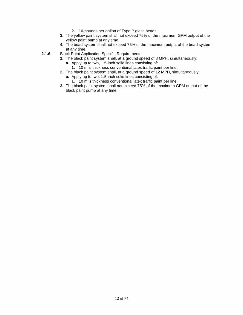
2. 10-pounds per gallon of Type P glass beads . 3. The yellow paint system shall not exceed 75% of the maximum GPM output of the
yellow paint pump at any time. 4. The bead system shall not exceed 75% of the maximum output of the bead system
at any time. 2.1.6. Black Paint Application Specific Requirements.
1. The black paint system shall, at a ground speed of 8 MPH, simultaneously: a. Apply up to two, 1.5-inch solid lines consisting of:
1. 10 mils thickness conventional latex traffic paint per line. 2. The black paint system shall, at a ground speed of 12 MPH, simultaneously:
a. Apply up to two, 1.5-inch solid lines consisting of: 1. 10 mils thickness conventional latex traffic paint per line.
3. The black paint system shall not exceed 75% of the maximum GPM output of the black paint pump at any time.
13 of 74
Section 3 Common Specific Requirements 3.1. GENERAL
3.1.1. All products provided by the Contractor shall be new, current production latest model products at the time of receipt of the purchase order. 1. Any product that is used, rebuilt, refurbished, reconditioned, remanufactured, or
otherwise not a new, current model product is not acceptable. 3.1.2. Each delivered Striper shall comply with all State of Missouri and Federal vehicle safety
requirements. 1. Each delivered striper shall be equipped with a fire extinguisher, warning triangles,
and spare fuses per FMCSA section 393.95. a. Fire extinguisher shall be installed inside the chassis cab. b. Fire extinguisher shall be 5-pound.
3.1.3. Unless otherwise specified at the time of order, each delivered Striper shall not exceed: a. 96-inches in width.
1. Excluding required safety equipment. b. 152-inches in height. c. 37-feet in length.
3.1.4. Each delivered Striper shall be complete with all standard equipment, plus any optional or special equipment to meet the minimum specifications as stated herein.
3.1.5. All items not specifically listed in this specification, but necessary for proper and efficient operation of each delivered Striper including all optional equipment, shall be supplied and included in the bid price.
3.1.6. Each delivered Striper shall be fully operational, with all hydraulic, pneumatic, and mechanical adjustments made prior to delivery.
3.1.7. Calibration of the paint and bead application systems shall be the responsibility of MoDOT.
3.1.8. Each delivered Striper shall have ALL grease fittings on the chassis and Body Builder installed components properly lubricated.
3.1.9. From the time it leaves the manufacturing facility, up to and including arrival at the MoDOT delivery location, the cab & chassis shall have the following minimum levels maintained at all times, 1. Minimum of ¼ tank of fuel. 2. Minimum of ¼ tank of DEF.
3.2. DETERMINING CHASSIS DIMENSIONS
3.2.1. Chassis dimensions. 1. This specification does not specify the listed dimensions:
a. WB b. CT/CA c. AF/EOF
2. These dimensions shall be determined by collaboration between the Contractor and/or Body Builder and chassis manufacturer. a. There shall be a minimum of 24-inches horizontal clearance between the rear of
all components of the chassis and the front of any Body Builder installed components.
b. Striper configuration shall mitigate exposure of the APU to heat from the chassis aftertreatment system.
3.2.2. Departure Angle. 1. The completed Striper shall have a departure angle of no less than 9-degrees. 2. Departure angle shall be defined as:

14 of 74
a. With the striper setting on a flat level plane, at fully loaded ride height, the angle formed between the plane the striper is resting on and a line formed by connecting: 1. The flat level plane at the point directly underneath the center of the rear
axle. 2. The lowest point of the rear bumper.
3.3. STRIPER WEIGHT
3.3.1. Each delivered Striper, when fully loaded with materials, fuel, and operators, shall comply with all legal weight limits for the State of Missouri, Section 304.180 RSMo, as they apply to non-commercial zone interstate highways.
3.3.2. Each delivered Striper, when fully loaded with materials, fuel, and operators, shall not exceed any chassis GAWR.
3.3.3. Weight Distribution Analysis. 1. Bidders shall submit a complete longitudinal and lateral certified weight distribution
analysis for each Striper bid. 2. Contractors shall submit a final weight distribution analysis for each proposed Striper
purchase, including all options and MSRP items. a. Final weight distribution analysis shall be approved by the MoDOT Fleet
Manager before a purchase order is issued. 3.4. VIN SPECIFIC STRIPER INFORMATION MANUAL
3.4.1. Each Striper shall be delivered with a VIN-number specific, printed paper manual meeting all of the following requirements. 1. Publications shall be bound into a single manual or installed in a binder when
delivered to MoDOT. a. Boxed, shrink-wrapped or otherwise unbound loose pages are not acceptable.
2. The VIN Specific Striper Information Manual shall include, but not be limited to: a. The entire VIN number of the delivered Striper on the cover of the manual. b. The 5-digit MoDOT unit number on the cover of the manual. c. A copy of the chassis pre-delivery inspection form as outlined in Section 1.4.1. d. A copy of the Body Builder pre-delivery inspection form as outlined in section
1.4.2. e. A copy of the chassis warranty policy as outlined in Section 4.4.1. f. Copies of the engine warranty policies as outlined in Section 4.5.1. g. A copy of the VIN specific chassis component line sheet as outlined in Section
4.8. h. Copies of the auxiliary power unit component warranties as outlined in Sections
7.3 and 7.4. i. A copy of the striping equipment warranty policies as outlined in Section 5.2. j. Copies of the Body Builder manufactured/installed components warranty policies
as outlined in Section 5.3. k. A list of repair stations authorized to perform warranty work on Body Builder
manufactured/installed components as outlined in Section 5.4. l. Telephone numbers for technical assistance for all cab & chassis and Body
Builder installed components. Numbers shall provide technical assistance during normal working hours, 8:00 AM to 4:00 PM Central Time.
m. A summary page listing the: 1. Make and model of all Body Builder installed components. 2. Serial number of each Body Builder installed component.
n. A maintenance items list as outlined in Section 3.5. o. Complete lubrication diagrams including fluid level checks and grease zerk
locations for the cab & chassis, and all Body Builder installed components. p. Complete, fully illustrated parts listings for all Body Builder installed components.

15 of 74
q. Schematics for each Body Builder installed electrical accessory circuit showing the complete power and ground sides, routing, wire color and gauge, pin numbers, switches, breaker or fuse location and/or number, and specific ground point locations.
r. Schematics for each Body Builder installed air powered accessory circuit showing valve location, air line color, air line size, and routing.
s. Schematics for each hydraulic accessory circuit, including flow specifications, and pressure limiter valve settings.
t. Schematics for each paint system circuit. u. Schematics for the bead system. v. A list of each hydraulic hose installed, including the diameter, overall length of
the hose including both fittings, and the type and size of each fitting. w. A manual for the LED warning light system including, but not limited to:
1. A complete wiring schematic. 2. A complete, illustrated parts list. 3. Diagnostic troubleshooting information.
3.5. MAINTENANCE ITEMS LIST
3.5.1. Each Striper shall be delivered with a comprehensive list of ALL maintenance items or items otherwise not listed necessary for the complete maintenance of the delivered Striper, including the chassis, APU, and striping unit. 1. This list shall include, but not be limited to:
a. Chassis. 1. Engine coolant. 2. Engine oil. 3. Power steering fluid. 4. Transmission fluid. 5. Front hub lubricant. 6. Drive axle lubricant. 7. Chassis grease.
b. Auxiliary Power Unit. 1. Engine coolant. 2. Engine oil. 3. Air compressor oil. 4. Hydraulic oil.
c. Part numbers of: 1. OEM chassis engine oil filter/s. 2. OEM chassis engine fuel filter/s. 3. OEM chassis engine air filter/s. 4. OEM chassis transmission filter/s. 5. OEM chassis power steering filter. 6. OEM auxiliary power unit engine oil filter/s. 7. OEM auxiliary power unit fuel filter/s. 8. OEM auxiliary power unit air filter/s. 9. OEM auxiliary power unit compressor air filter. 10. OEM auxiliary power unit compressor oil filter. 11. OEM auxiliary power unit hydraulic filter.
2. This list shall include the type, weight, grade, and identifying information such as product name and/or number.
3. This list shall be provided in the VIN specific Striper Information Manual. 3.6. OPERATOR TRAINING
3.6.1. Operator training shall be provided covering the entire delivered Striper. 1. All training specified in Section 3.6 shall be provided for each delivered Striper.

16 of 74
2. All costs associated with training are the responsibility of the Contractor. 3.6.2. Operator training shall be conducted by a qualified trainer.
1. Qualifications for trainers shall include, but are not limited to: a. A manufacturers regular trainer. b. A qualified manufacturer’s technician.
1. Trainers shall have considerable experience in the area they are training on. 3.6.3. Operator training shall be coordinated with a MoDOT representative at the Stripers
assigned location. 1. Training schedule shall include 5 consecutive days of training. 2. Training content shall be tailored to the components installed on the delivered
Striper. 3. Training content shall include hands-on training as well as verbal instruction. 4. Training schedule shall include, but not be limited to:
a. Cab & chassis safe operation, features, component identification, and preventive maintenance including: 1. Engine. 2. Transmission. 3. Fuel system. 4. Electrical system. 5. Aftertreatment system.
b. Striper setup and calibration. c. Striper safe operation, features, component identification, and preventive
maintenance including: 1. APU. 2. Hydraulic system. 3. Compressed air system. 4. Paint system plumbing and filters. 5. Bead system. 6. Skip line timer.
5. In the event the training does not meet the requirements and/or needs of MoDOT, the Contractor shall conduct the training again.
3.6.4. A list of available training materials shall be submitted with the bid. 1. Training materials may include, but not be limited to:
a. Videos. b. CDs. c. Books and /or manuals. d. Online training.
3.7. KEY SET
3.7.1. Each completed Striper shall be delivered with two complete sets of keys: 1. Ignition. 2. Door lock. 3. Tool boxes. 4. Rear operators cab.
3.7.2. Each complete set of keys shall be identified with a key tag identifying the MoDOT unit number. 1. MoDOT unit number shall be supplied to the Contractor.

17 of 74
Section 4 Cab & Chassis Specifications All specified cab & chassis equipment shall be OEM installed, either as standard equipment, a line installed option or factory authorized DSO/SE installation unless otherwise specifically stated. 4.1. CAB & CHASSIS MAKE AND MODEL
4.1.1. Acceptable cab & chassis makes are: 1. Peterbilt. 2. Mack. 3. Autocar.
a. All submitted cab & chassis shall meet all requirements listed in Section 4. 4.2. DRIVETRAIN CONFIGURATION
4.2.1. Documentation. 1. Bidder shall provide SCAAN reports for each chassis/engine combination and rear
axle ratio that are submitted. a. SCAAN reports shall include both 5-speed and 6-speed automatic transmission
configurations. 4.2.2. Final Drivetrain Configuration.
1. The final drivetrain configuration shall be approved by the MoDOT Representative at the time of order.
4.3. OPERATIONAL PERFORMANCE
4.3.1. The cab & chassis shall be capable of performing, without hesitation or fail, all items listed in Section 4.3.1 and Section 4.3.2 of this specification at a duty cycle of 100% while all operating conditions occur simultaneously. 1. Operating Conditions.
a. Gross Striper weight of 60,000 LBS. b. Ambient air temperatures of 35-105 degrees Fahrenheit. c. Relative humidity of 90%. d. Striping uphill on a 6% grade. e. Ground speeds of 8 MPH and/or 12 MPH. f. Use of B20 diesel fuel.
4.3.2. Striping Speed Performance. 1. The Striper drivetrain shall be configured to provide and maintain striping speeds
and chassis engine RPMs of: a. 8 MPH @ 1400-1650 engine RPM. b. 12 MPH @ 1400-1650 engine RPM.
2. The striper drivetrain shall incorporate a speed control system to control the ground speed of the striper at striping speeds. a. Speed control system shall maintain the actual ground speed of the fully loaded
striper to within 2.5% +/- of the selected speed while striping uphill on grades of up to 6%.
4.3.3. Road Speed Performance. 1. The maximum road speed parameter in the engine ECM shall be programmed to 65
MPH. a. The maximum road speed parameter shall be adjustable by MoDOT.
2. The Striper drivetrain shall be configured to provide road speeds and engine RPMs as listed: a. 65 MPH @ 1750-2000 engine RPM.
18 of 74
4.4. CHASSIS WARRANTY
4.4.1. The chassis manufacturer and/or its representative shall guarantee to furnish all warranty services gratis at franchised dealers. The chassis warranty coverage shall be the manufacturers standard base warranty package. 1. Warranty policy effective period shall begin:
a. At the in-service date with MoDOT. b. At the in-service mileage with MoDOT.
1. Example: If a Striper is put in service on May 1st, 2017, and has 650 miles on the odometer, the warranty policy effective time period shall begin at that date, and the warranty policy effective mileage period shall begin at 650 miles, not zero miles.
2. Contractor shall provide printed paper copies of the chassis warranty policy including: a. Covered components. b. Length of coverage.
3. Printed paper copies of the chassis warranty policy shall be included: a. In the bid submission. b. In the VIN Specific Striper Information Manual.
4.5. ENGINE WARRANTY
4.5.1. The engine manufacturer and/or its representative shall guarantee to furnish all warranty services gratis at franchised dealers. The engine warranty coverage shall be the manufacturers standard base warranty package. 1. Warranty policy effective period shall begin:
a. At the in-service date with MoDOT. b. At the in-service mileage and/or hours with MoDOT.
1. Example: If a Striper is put in service on May 1st, 2017, has 650 miles on the odometer, and 40 hours on the hourmeter, the warranty policy effective time period shall begin at that date, the warranty policy effective mileage period shall begin at 650 miles instead of zero miles, and the warranty policy effective hours period shall begin at 40 hours instead of zero hours.
2. Contractor shall provide printed paper copies of the engine warranty policy including, but not limited to: a. The engine manufacturers warranty policy including:
1. Covered components. 2. Length of coverage.
b. The Federal Emissions Warranty coverage including: 1. Covered components. 2. Length of coverage.
3. Printed paper copies of all engine warranty policies shall be included: a. In the bid submission. b. In the VIN Specific Striper Information Manual.
4.6. OPERATOR MANUALS
4.6.1. Two complete sets of printed paper operator manuals covering the complete cab & chassis shall be provided. 1. Manuals shall include, but not be limited to:
a. Cab & chassis. b. Engine. c. Transmission. d. All applicable OEM installed components.
19 of 74
4.7. PARTS AND SERVICE MANUALS
4.7.1. Two complete sets of parts and service manuals covering the complete cab & chassis shall be provided. 1. Manuals shall include, but not be limited to:
a. Cab & chassis. b. Engine. c. Transmission. d. Electrical system. e. HVAC.
2. Manuals shall include: a. Illustrated parts listings. b. Diagnostic procedures. c. Wiring schematics. d. Repair procedures.
3. Manuals shall be either: a. Printed paper copies. b. CDs. c. Online access to manufacturer web sites.
1. Online access shall be provided for the entire duration of MoDOT’s ownership of the Striper. Contractor shall be responsible for all costs associated with online access.
4.8. LINE SHEET
4.8.1. Each Striper shall be delivered with a factory line sheet listing all chassis component codes as installed by the chassis manufacturer. 1. The factory line sheet shall include the entire VIN number of the Striper. 2. The factory line sheet shall be included in the VIN Specific Striper Information
Manual. 4.9. BRAKES
4.9.1. System Type. 1. Shall be full dual air system with four-channel minimum anti-lock system, rated at or
above GAWR requirements. 4.9.2. Compressor.
1. Shall be 18 CFM or greater displacement. 4.9.3. Air Dryer.
1. Shall have a thermostatically controlled heating element. 2. Shall have a replaceable, spin-on desiccant cartridge.
a. Replacement of desiccant cartridge shall not be obstructed by any component. 4.9.4. Air tanks.
1. The ‘wet tank’ shall have an automatic moisture ejector installed. 2. All other air tanks shall have manual, spring loaded drain valves with cable lanyards
attached. a. Lanyards shall be routed and attached to a location near the outside of all Body
Builder installed striping components. 1. Lanyards shall allow for draining of air tanks without having to crawl/reach
under Striper. 2. Lanyards shall pull smoothly and without rubbing/chafing against any
components. 3. Pulley/s and/or conduit/s shall be installed when necessary.
4.9.5. Front Brakes.
20 of 74
1. Shall be self-adjusting, rated at or above GAWR. 2. Shall have full-circle dust shields.
4.9.6. Rear Brakes. 1. Shall be self-adjusting, rated at or above GAWR. 2. Drum brakes shall have long stroke brake chambers. 3. Shall have full-circle dust shields. 4. Shall have spring-brake chambers at all four drive wheel positions.
4.9.7. Striping Equipment Compatibility. 1. Contractor and/or Body Builder shall collaborate with the chassis manufacturer to
provide air tanks and an air dryer meeting the listed specifications that do not interfere with the installation of striping equipment.
4.10. CAB
4.10.1. Design. 1. Shall be low-entry, cab-forward. 2. Design shall be suitable to provide adequate headroom with the specified air-ride
seats and other equipment installed inside the cab. 4.10.2. Cab Tilt.
1. Cab shall be equipped with a hydraulic cab tilting jack and hydraulic rams. a. Cab tilt system shall include mechanical safety supports to hold the cab in the
tilted position. 4.10.3. Color.
1. Cab shall be Highway Yellow or School Bus Yellow in color. 4.10.4. Interior Features and Trim.
1. Interior trim and insulation package shall include a full headliner and back-of-cab trim panels. a. Interior trim and insulation package shall be the highest sound deadening and
temperature protection level available. 2. Shall include interior sun visors for both driver and passenger. 3. Shall have an overhead console suitable for installing a two-way radio. 4. Floor covering shall be a heavy-duty rubber or vinyl floor mat with sound deadening
backing covering entire floor. a. Floor mat shall be black in color.
5. Passenger door window shall be power raise and lower. a. Driver door window may be manual or power raise and lower.
6. Door Armrests. a. Driver’s and passenger’s door shall be equipped with integral arm rests.
1. Outboard adjustable armrests on the driver and passenger seats may be provided in lieu of integral door armrests.
4.10.5. Cab Entry. 1. Cab entry requirements shall apply for the driver’s side and passenger’s side of the
cab. 2. Cab Steps.
a. All external steps shall be self-cleaning and have a serrated, cleated, or similar design to prevent slipping off step.
3. Grab Handles. a. Grab handles shall be configured to provide continuous three points of contact
while entering or exiting the cab. Acceptable locations for grab handles include, but are not limited to: 1. Mounted to the interior of the door. 2. Mounted to the A-Pillar. 3. Mounted externally to the B-Pillar. 4. Mounted internally to the B-Pillar.
4.10.6. Mirrors. 1. Shall be west-coast breakaway type, left and right.

21 of 74
2. Shall both be power adjustable. a. Power adjust shall be electric, controlled by switches.
3. Shall both be approximately 6-inches by approximately 16-inches in size.
4.10.7. Convex Mirrors. 1. Shall be mounted below primary west coast mirrors, left and right. 2. Shall both be approximately 8-inches round or approximately 6-inches x 6-inches
square. 4.10.8. Heater, Air Conditioner, and Defroster.
1. A/C shall be the standard unit with in-dash evaporator and condenser in front of the radiator.
2. Shall have a replaceable fresh air filter element. 4.10.9. Driver and Passenger Seats.
1. Shall both be vinyl or Fabriform covered, high-back, with air suspension. 2. Driver and passenger seats shall have full range of travel of the fore and aft seat
adjustment. a. No Body Builder installed components shall be mounted behind either seat that
inhibits full range of travel. 4.10.10. Seat Belts.
1. Shall be 3-point design, and tethered to allow free suspension movement. 2. Shall be either red or orange in color.
4.10.11. Steering. 1. Shall have a factory tilt column. 2. Shall have the smallest diameter steering wheel available for the specified front axle.
4.10.12. Window Tint. 1. All windows shall be tinted.
4.10.13. Horns. 1. Shall have an electric city horn. 2. Shall have dual air horns mounted to the top of the cab.
a. Both air horns shall have snow covers. 4.10.14. Windshield Wipers.
1. Shall be two-speed electric, with intermittent operation. 4.10.15. Front Grille.
1. Shall have a factory installed bug and stone screen. 4.11. CHASSIS
4.11.1. Color. 1. Chassis shall be black. 2. No ferrous metal, whether visible or not, shall be left bare or otherwise un-finished
anywhere on the chassis. 4.11.2. Frame.
1. Rail strength shall be 110,000 PSI minimum. 2. Rail RBM shall be 2,000,000 in/lbs minimum. 3. Double-rail or laminated frame rails shall have corrosion protection applied between
the rails. 4.11.3. OEM Tow Hooks.
1. Chassis shall be ordered with: a. Two front tow hooks.
4.11.4. Power Steering. 1. Shall be integral hydraulic gear. 2. Hydraulic ram system is not acceptable.
4.11.5. Chassis dimensions. 1. This specification does not specify the listed dimensions:
a. WB b. CT/CA

22 of 74
c. AF/EOF 2. These dimensions shall be determined by collaboration between the Contractor
and/or Body Builder and chassis manufacturer. a. There shall be a minimum of 24-inches horizontal clearance between the rear of
all components of the chassis and the front of any Body Builder installed components.
4.12. ELECTRICAL
4.12.1. Alternator. 1. Shall be 200-ampere minimum. 2. Shall have the capacity to handle all chassis and Body Builder installed components.
4.12.2. Batteries. 1. Chassis shall have three maintenance free, 12 volt batteries. 2. The three batteries shall have a minimum total combined CCA of 1950. 3. All battery cables shall be uninterrupted with no splices.
4.12.3. Battery Box. 1. Shall be mounted on the left hand side of the chassis. 2. Contractor and/or Body Builder shall collaborate with the chassis manufacturer to
provide a battery box meeting the listed specifications that does not interfere with the installation of striping equipment installed at the time of purchase.
4.12.4. Battery Disconnect. 1. Chassis shall be equipped with a battery disconnect switch.
a. Disconnect switch shall be factory installed by the chassis manufacturer. 4.12.5. Power Outlet.
1. A minimum of two 12-volt accessory power outlets shall be provided inside the cab. 2. A USB port shall be provided inside the cab.
4.12.6. Instrumentation. 1. Shall include an analog gauge for:
a. Speedometer. b. Tachometer. c. Engine coolant temperature. d. Engine oil pressure. e. Brake system air pressure. f. Automatic transmission temperature. g. Fuel.
2. Shall have a visual indicator for: a. Low electrical system voltage. b. DEF tank level.
3. Shall have an audible buzzer/beeper and warning lamp for: a. Low engine oil pressure. b. High engine coolant temperature. c. Low engine coolant level. d. Low brake system air pressure.
4. Shall have an OEM electronic hourmeter. a. Hourmeter shall provide true engine running hours-of-operation.
4.12.7. Ignition Switch. 1. Automotive type key switch with accessory position.
4.12.8. Windshield Wiper System. 1. Shall be electric, with intermittent operation. 2. Shall have an electric washer pump.
4.12.9. Radio. 1. Shall have an AM/FM stereo radio with dual speakers.
4.12.10. Courtesy Lights. 1. OEM courtesy lights shall be LED if available. 2. OEM courtesy lights shall fully illuminate:

23 of 74
a. Cab interior. b. Driver’s floorboard. c. Passenger’s floorboard. d. All drivers’ side steps. e. All passengers’ side steps.
3. Step illumination from amber marker lights in lieu of illumination from courtesy lights is acceptable.
4.12.11. Turn Signal Switch. 1. Turn signal switch shall be self-canceling.
4.12.12. Marker and Turn Lights. 1. Cab marker lights shall be LED. 2. Cab turn signal lights shall be LED.
4.13. ENGINE
4.13.1. Type. 1. Engine shall be a Cummins ISL 9, Paccar PX-9, or Mack MP8. 2. Ratings:
a. Engine shall have a minimum gross torque of 1,150 pound-feet. b. Engine shall have a minimum gross horsepower of 345.
3. Engine shall be capable of operating on B20 diesel fuel. 4.13.2. Automatic Shut-Down System.
1. Engine shall have an automatic shut-down system consisting of an audible buzzer/beeper, a warning lamp, and automatic engine shutdown for the following conditions: a. Low engine oil pressure. b. High engine coolant temperature. c. Low engine coolant level.
4.13.3. Drain Plug. 1. Engine oil pan shall have a magnetic drain plug.
4.13.4. Idle Shut Down Timer. 1. Engine shall be equipped with a programmable electronic idle shut down timer.
a. Timer shall be set to shut the engine off after 10 minutes of idle with the parking brake on.
b. Timer shall be adjustable by MoDOT. 4.13.5. Cruise Control.
1. Chassis shall be equipped with cruise control. 4.13.6. Electronic Auxiliary Throttle.
1. Engine shall have an electronic auxiliary throttle capable of controlling engine RPM independently of the accelerator pedal. a. Electronic auxiliary throttle shall be controlled by switch/es located either in the
steering wheel or the dash. b. Electronic auxiliary throttle shall be capable of setting and maintaining engine
speed infinitely from idle to 2000RPM. 4.13.7. Governor.
1. Engine governor shall be programmed as a variable speed governor. 4.13.8. Engine Brake.
1. A compression type engine brake shall be provided. a. Exhaust brakes are not acceptable. b. Compression brake shall be operator selectable.
4.14. FUEL SYSTEM
4.14.1. Fuel Capacity. 1. Total usable fuel capacity shall be 100 gallon minimum.
4.14.2. Fuel Tank.

24 of 74
1. Fuel tank shall be: a. A single tank. b. Mounted on the left side of the cab & chassis c. Non-polished aluminum. d. Equipped with a drain port with removable plug.
2. Fuel tank shall not make contact with: a. Any battery cables. b. Any hydraulic hose. c. Any high-current electrical circuit.
3. Contractor and/or Body Builder shall collaborate with the chassis manufacturer to provide a fuel tank meeting the listed specifications that does not interfere with the installation of striping equipment.
4.14.3. Fuel Maintenance System. 1. Fuel-water separator shall:
a. Be equipped with a thermostatic fuel-temperature controlled electric heater. b. Be equipped with a replaceable fuel filter element. c. Be located between the fuel tank and fuel primer pump.
4.14.4. Fuel Tank Heater. 1. If the fuel system on the provided engine does not return fuel to the fuel tank, a
thermostatically controlled in-tank heater shall be provided. 4.15. COOLING SYSTEM
4.15.1. Capacity. 1. The entire cooling system shall be the highest capacity available for the
chassis/engine combination provided. 4.15.2. Fan Clutch
1. Fan clutch shall be a 2-speed type. 4.15.3. Radiator.
1. Radiator shall have an accessible drain petcock. a. If a quick-coupler style drain valve is used, the necessary mating coupler shall be
provided with each delivered Striper. 4.15.4. Coolant.
1. Engine shall have extended life coolant meeting the engine manufacturers’ recommendation.
2. Engine coolant shall test to -34 degrees Fahrenheit. 4.15.5. Block Heater.
1. Engine shall be equipped with a 120-volt, 1000-watt minimum block heater. 2. Block heater electrical receptacle shall:
a. Be mounted near the drivers’ door. b. Have a hinged protective cover. c. Be accessible from the ground without reaching under the cab.
4.16. ENGINE AIR INTAKE SYSTEM
4.16.1. Restriction Indicator. 1. An engine air intake restriction indicator shall be provided.
4.17. EXHAUST AND AFTERTREATMENT
4.17.1. Exhaust Stack. 1. Exhaust stack shall be vertical. 2. Exhaust stack shall have a sweep elbow to direct exhaust and heat above and away
from the cab. 3. Exhaust stack shall be shielded the full height of the cab.
4.17.2. Flex Tubing.

25 of 74
1. If flex tubing is used, both the clamps and tubing shall be stainless steel. 4.17.3. Striping Equipment Compatibility.
1. Contractor and/or Body Builder shall collaborate with the chassis manufacturer to provide an exhaust/aftertreatment system meeting the listed specifications that does not interfere with the installation of striping equipment. a. There shall be a minimum of 24-inches clearance between all components of the
exhaust and aftertreatment system, and the front of any Body Builder installed components.
4.17.4. DEF Tank. 1. DEF tank shall be of sufficient capacity to run out a minimum of two full tanks of
diesel fuel with the engine operating under a continuous heavy load before the DEF tank needs to be refilled.
4.18. FRONT AXLE AND SUSPENSION
4.18.1. 20,000 lb. Minimum Front GAWR. 1. All front axle components and front suspension components shall be rated to
provide a minimum front GAWR of 20,000 lbs. 4.18.2. Front Suspension Springs.
1. Front suspension springs shall be parabolic or tapered leaf. a. Multi-leaf, flat-spring packs are not acceptable.
4.18.3. Front Suspension Shock Absorbers. 1. Front axle suspension shall be equipped with shock absorbers.
4.18.4. Front Axle Mud Flaps. 1. Chassis shall be equipped with mud flaps for both front axle tires.
4.19. REAR AXLE AND SUSPENSION
4.19.1. 40,000 lb. Minimum Rear GAWR. 1. All rear axle components and rear suspension components shall be rated to provide
a minimum rear GAWR of 40,000 lbs. 4.19.2. Rear Axle.
1. Shall be a tandem axle with lockable power divider. 2. All drain plugs shall be magnetic.
4.19.3. Rear Suspension. a. Shall be a four-bag air suspension.
1. Suspension shall include dual leveling valves configured for side-to-side leveling.
b. Shock absorbers shall be provided. 4.19.4. Rear Fenders.
1. Full-length fenders shall be provided to cover the tires of the forward and rear axle. a. Fenders shall be of poly or aluminum.
1. Poly fenders shall be a minimum of 11-gauge material. 2. Aluminum fenders shall be a minimum of 15-gauge material.
b. Fenders shall be easily removable for servicing of Striper components. c. Fenders shall be equipped with anti-sail mud flaps at the front and rear.
4.20. TRANSMISSION
4.20.1. Allison Automatic Transmission. 1. Striper shall be equipped with a medium duty Allison automatic transmission.
a. Shall be a Rugged Duty Series transmission. b. Shall have a dash-mounted push-button shifter with mode button. c. Shall have Allison approved synthetic transmission fluid. d. Shall have a magnetic drain plug. e. Shall utilize a heavy-duty external transmission cooler.

26 of 74
f. Transmission programming shall include converter lock-up in first gear. 4.21. WHEELS AND TIRES
4.21.1. Front Wheels. 1. Front wheels shall be:
a. Heaviest service available. b. 12.25-inch. c. Hub-piloted. d. 10-bolt, 11.25” pattern. e. White powder coat finish or aluminum.
4.21.2. Front Tires. 1. Shall be tubeless, 425/65R22.5. 2. Shall be 20 ply rating, load range “L”. 3. Shall have steer axle tread design. 4. Shall not be speed restricted below 65 MPH.
4.21.3. Dual Rear Wheels. 1. Rear wheels shall be:
a. Heaviest service available. b. 8.25-inch steel. c. Hub-piloted. d. 10-bolt, 11.25” pattern. e. White powder coat finish.
4.21.4. Dual Rear Tires. 1. Shall be tubeless, 11R22.5. 2. Shall be 16 ply rating, load range “H”. 3. Shall have traction tread design. 4. Shall not be speed restricted less than 65 MPH.
4.21.5. Wheel Guards. 1. Nylon wheel guards for hub-piloted wheels shall be installed:
a. Between the front wheels and hubs. b. Between the rear wheels and hubs. c. Between the dual wheels.
27 of 74
Section 5 Body Builder General Requirements 5.1. APPLICABILITY OF BODY BUILDER GENERAL REQUIREMENTS
5.1.1. All requirements listed in Section 4 shall apply to ALL Body Builder installed components/items including, but not limited to: 1. All Body Builder installed components/items listed as standard items. 2. All Body Builder installed components/items listed as optional items. 3. All Body Builder installed components/items that may be purchased additionally as
M.S.R.P. items. 5.2. STRIPING EQUIPMENT WARRANTY
5.2.1. The striping equipment manufacturer and/or the Body Builder and/or its representative shall guarantee to furnish all warranty services, including parts, shipping costs, and labor, gratis at authorized repair stations. The striping equipment warranty shall be the manufacturer’s standard base warranty, or 12 months, whichever is longest. 1. At the sole discretion of MoDOT, reimbursement for warranty labor provision may,
for each warrantable repair considered individually, be waived and those warranty repairs made in-house to the expedite the repair process.
2. Warranty policy effective period shall begin: a. After completion of the Trial Period and upon final approval of the Striper as
described in Section 1.7. 3. Body Builder shall provide printed paper copies of the striping equipment warranty
policies for the equipment installed on each delivered Striper. 4. Printed paper copies of the striping equipment warranty policies shall include:
a. Covered components. b. Length of coverage.
5. Printed paper copies of the striping equipment warranty policy shall be included: a. In the bid submission. b. In the VIN Specific Striper Information Manual.
5.3. BODY BUILDER MANUFACTURED/INSTALLED COMPONENTS WARRANTY
5.3.1. The Body Builder and/or its representative shall guarantee to furnish all warranty services, including parts, shipping costs, and labor, gratis at authorized repair stations. The Body Builder manufactured/installed components warranty shall be the manufacturer’s standard base warranty, or 12 months, whichever is longest. 1. At the sole discretion of MoDOT, reimbursement for warranty labor provision may,
for each warrantable repair considered individually, be waived and those warranty repairs made in-house to the expedite repair process
2. Warranty policy effective period shall begin: a. After completion of the Trial Period and upon final approval of the Striper as
described in Section 1.7. 3. Body Builder shall provide printed paper copies of the Body Builder
manufactured/installed components warranty policies for the components installed on each delivered Striper.
4. Printed paper copies of the Body Builder manufactured/installed components warranty policies shall include: a. Covered components. b. Length of coverage.
5. Printed paper copies of the Body Builder manufactured/installed components warranty policies shall be included: a. In the bid submission. b. In the VIN Specific Striper Information Manual.
28 of 74
5.4. AUTHORIZED REPAIR STATIONS
5.4.1. The Body Builder shall provide a list of any authorized repair stations that may perform warranty repairs on all Body Builder manufactured/installed components on the Striper. 1. The list of authorized repair stations shall be included in the VIN Specific Striper
Information Manual. 5.4.2. These stations shall handle all associated billing directly with the Body Builder.
5.5. TRANSPORTATION OF STRIPER FOR WARRANTY REPAIR
5.5.1. Transportation of the Striper to and from the Body Builder and/or component manufacturer’s location for warranty repairs of Body Builder installed components shall not accumulate mileage on the Striper chassis odometer or hours on the chassis engine hourmeter. 1. Striper transportation methods shall include, but not be limited to:
a. Hauling Striper on a low-boy trailer. b. Towing Striper.
2. All costs associated with transport of the Striper shall be the responsibility of the Contractor.
3. Pickup and delivery of Striper shall be coordinated with a MoDOT Representative at the Stripers assigned location. a. Contractor shall give a minimum of 24 hours advance notice before pickup and
delivery of a Striper. b. Pickup and delivery of a Striper shall only be received between the hours of 8:00
a.m. to 3:00 p.m., Monday through Friday. c. Deliveries shall not be made on observed holidays as identified in the attached
terms and conditions. 4. The Contractor shall be financially responsible for all damage to the Striper received
from transit/shipping. a. MoDOT shall have five business days after receipt of Striper to inspect the
Striper for damage received during transport. 1. Damage shall be listed and communicated to the Contractor. 2. The Contractor shall address the listed items to the satisfaction of the
MoDOT Representative/s. 5.6. OPERATOR MANUALS
5.6.1. Two complete sets of printed paper operator manuals for all Body Builder manufactured/installed components, striping equipment, and striping control system shall be provided with each delivered Striper.
5.7. SERVICE MANUALS FOR BODY BUILDER SUPPLIED COMPONENTS
5.7.1. Service manuals for all Body Builder supplied components shall be made available. 1. Service manuals shall include diagnostic, repair, adjustment, and calibration
information for, but not be limited to: a. The APU. b. The entire hydraulic system. c. The entire pressurized air system. d. The entire electrical system. e. Paint pumps. f. Paint plumbing. g. Striping control system.
5.7.2. Service manuals may be: 1. Printed paper manuals. 2. Word documents.

29 of 74
3. PDF documents. 4. Online.
5.8. PAINT AND FINISH
5.8.1. All equipment and components, except those constructed of stainless steel or aluminum, shall be thoroughly cleaned, prepped, primed, and completely finished with a high quality corrosion resistant paint or powder coat. 1. Finish shall be smooth, shiny, and free of runs, overspray, and/or other defects. 2. Whether visible or not, no metal shall be left bare or otherwise un-finished anywhere
on the chassis, or any OEM and/or Body Builder installed components, except for the listed exceptions: a. Stainless steel may be bare. b. Aluminum may be bare.
3. Body Builder manufactured components installed on and including the platform shall be Highway Yellow or School Bus Yellow. These items include, but are not limited to: a. Platform. b. Rear operator’s cab. c. Paint tanks. d. APU enclosure.
1. Highway yellow or School Bus Yellow paint applied by the Body Builder shall match the color of the chassis cab.
4. Frame mounted components shall be black. 5.8.2. Body accessories that are required to be welded on, i.e., ladders, etc., are to be
installed by the Body Builder prior to paint prep. 5.8.3. The Body Builder shall touch-up any chassis factory applied paint damaged during
component installation. 1. Touch-up process and finish shall be of quality equal to the original chassis factory
applied paint. 5.9. BODY BUILDER INSTALLED THREADED FASTENERS
5.9.1. All threaded fastener components (screws/bolts, washers/lock washers, nuts) with a
diameter designation less than SAE ¼-inch shall: 1. Be a minimum grade 2 composition. 2. Have a minimum of two bolt threads extending through all nuts.
5.9.2. All threaded fastener components (bolts, washers, nuts) with a diameter designation equal to or greater than SAE ¼-inch but less than SAE ½-inch shall: 1. Be minimum grade 5 composition. 2. Be secured with self-locking nuts, either poly-lock or all metal.
a. Lock washers are not acceptable, except when a bolt is installed in a fixed, non-rotating threaded bore.
3. Have a minimum of two bolt threads extending through all nuts. 4. Have grade identifier marks.
5.9.3. All threaded fastener components (bolts, washers, nuts) with a diameter designation of SAE ½-inch shall: 1. Be minimum grade 8 composition. 2. Be secured with all metal self-locking nuts.
a. Lock washers are not acceptable, except when a bolt is installed in a fixed, non-rotating threaded bore.
3. Have a minimum of two bolt threads extending through all nuts. 4. Have grade identifier marks.
5.9.4. All threaded fastener components (bolts, washers, nuts) with a diameter designation equal to or greater than SAE 5/8-inch shall: 1. Be minimum grade 8 composition.
30 of 74
2. Be flange head bolts. 3. Be secured with flange head, all metal lock nuts.
a. Lock washers are not acceptable, except when a bolt is installed in a fixed, non-rotating threaded bore.
4. Have grade identifier marks. 5.10. BODY BUILDER INSTALLED ELECTRICAL AND WIRING
5.10.1. All electrical systems installed by the Body Builder shall be: 1. 12-volts. 2. Supplied from the auxiliary power unit’s electrical system. 3. Connected to the battery disconnect switch for the auxiliary power unit. 4. Have circuit protection located at or near the battery disconnect switch for the
auxiliary power unit. 5.10.2. All Body Builder installed wiring, harnesses, wiring looms, cables, and/or otherwise
unlisted electrical conductor or assembly of conductors shall be: 1. Routed in a manner to minimize rub points.
a. Critical rub points shall be wrapped for protection. 2. Routed or shielded to protect wiring from heat sources. 3. Enclosed in a protective wiring loom or conduit. 4. Of adequate gauge to handle the anticipated loads of all electrical components. 5. Uninterrupted with no splices. 6. Color-coded or clearly numbered with permanent markings. 7. Supported, stress-relieved, and secured.
a. All wiring, harnesses, wiring looms, cables, and/or otherwise unlisted electrical conductor or assembly of conductors shall: 1. Bear no part of its weight on any terminals/connectors. 2. Be supported and secured no more than 8-inches from the
terminals/connectors at the end/s of the aforementioned conductors/assemblies of conductors.
3. Be of sufficient length to allow for full travel of the actuator that controls the position of any movable component.
b. Flexible looms/conduits and wiring harnesses shall be supported and secured at intervals of no more than 10-inches.
5.10.3. The edges of all holes through which wiring, harnesses, wiring looms, cables, and/or otherwise unlisted electrical conductor or assembly of conductors must pass shall be protected with a grommet.
5.10.4. Wiring harnesses routed through an exterior wall of either the chassis cab or the rear operator cab shall pass through weather-proof strain relief/s in the wall of the cab. 1. Strain relief shall be the primary support for the wiring harnesses and shall, without
the aid of a sealant, hold the wiring harnesses in place. 2. Wiring harnesses shall be routed so that the height of the harness/s outside the cab
decreases as it/they travel away from the strain relief/s. a. Any water following the harnesses/s shall run away from the strain relief/s.
3. Wiring harnesses shall have sufficient slack to allow full travel up and full travel down of the chassis cab while being tilted with the cab jack without pulling on the harnesses.
5.10.5. Universal wire terminal ends (spade, ring, etc.) shall be either: 1. High grade, heavy duty terminals that are crimped, soldered to the wires with rosin-
core solder and protected with heat shrink tubing. 2. High grade, heavy duty insulated crimp terminals with built-on heat shrink.
a. Scotch-Loc fasteners are not acceptable for any connection. 5.10.6. All electrical connections outside of the chassis cab or rear operator’s cab shall be one
of the listed types: 1. Sealed, serviceable connectors. 2. Inside an ISO IP68/NEMA 6 rated enclosure.

31 of 74
a. Wiring harnesses routed through an exterior wall of the enclosure shall pass through weather-proof strain relief/s in the wall of the enclosure. 1. Strain relief shall be the primary support for the wiring harnesses and shall,
without the aid of a sealant, hold the wiring harnesses in place. 2. Wiring harnesses shall be routed so that the height of the harness/s outside
the enclosure decreases as it/they travel away from the strain relief/s. 3. Any water following the harnesses/s shall run away from the strain relief/s.
b. Connections shall be made utilizing an insulated terminal strip with threaded studs or screws.
5.10.7. All electrical components shall have sealed, serviceable connectors to allow for easy component replacement without cutting/splicing of any wire. Electrical components shall include, but not be limited to: 1. Valve coils. 2. Sensors. 3. Switches. 4. Motors.
5.10.8. All electronic circuitry shall have appropriate transient voltage spike protection. 5.11. BODY BUILDER INSTALLED AIR POWERED ACCESSORY INSTALLATION
5.11.1. Air supply for all Body Builder installed air powered accessories shall originate from the auxiliary power unit air compressor.
5.11.2. All Body Builder installed air lines shall be: 1. Routed in a manner to minimize rub points and kinks.
a. Critical rub points shall be wrapped for protection. 2. Routed or shielded to protect them from heat sources. 3. Colored, identifying individual circuits, with each circuit being a different color.
5.11.3. Air lines routed through an exterior wall of either the chassis cab or the rear operator cab shall pass through bulkhead unions in the wall of the cab.
a. The bulkhead unions shall pass through matching backup plates located on the inside and outside of the cab wall. 1. Both backup plates shall be constructed from stainless steel.
b. The outside backup plate shall be coated with a polyurethane or silicone sealer before being secured to the outside wall of the cab.
c. All bulkhead locations shall have the function for that bulkhead labeled. Labeling methods shall be one of the following: 1. Stamped or etched into the outside backup plate. 2. High quality decal on the wall of the cab next to the bulkhead backup plate.
d. A diagram of the bulkhead function locations shall be included in the VIN Specific Striper Information Manual.
5.11.4. Manually operated air valves shall be ¼-turn ball valves, and color-coded. 5.11.5. Electrically Operated Air Valves.
1. Electrically operated air valves shall be Humphrey M420 mounted to a Humphrey SB-2 manifold, or pre-approved equivalent. a. Valves shall be individual direct-acting valve assemblies fastened to a manifold.
1. Valve coils shall be individually replaceable without removing the valve itself. 2. Manifold shall allow for one valve to be replaced without having to remove
adjacent valves or any plumbing. b. Valve coils shall be:
1. Rated for continuous duty. 2. Have sealed DIN connectors.
c. Valves shall: 1. Have manual overrides.
2. Electrically operated air valves mounted outside the rear operator’s cab shall be protected by weather resistant covers. a. Weather resistant covers shall:

32 of 74
1. Be made from metal. 2. Protect valve assemblies from rain, road spray, and pressure washing. 3. Be removable with simple hand tools.
5.12. BODY BUILDER INSTALLED HYDRAULIC POWERED ACCESSORY INSTALLATION
5.12.1. All hydraulic fittings shall be steel, hydraulic grade fittings rated for at least 3000 PSI. 1. Galvanized or black-iron fittings are not acceptable.
5.12.2. All hydraulic pressure ports, return ports, and work ports shall be ORB. 5.12.3. All hydraulic hoses shall be rated for at least 3000 PSI working pressure.
1. The hydraulic pump suction hose is exempt from this requirement. 5.12.4. Unless otherwise specified, all hydraulic hose ends shall be:
1. JIC 37 degree flare. 2. Female. 3. Swivel.
5.12.5. Hydraulic hoses shall be: 1. Routed in a manner to minimize rub points and bends.
a. Critical rub points shall be wrapped for protection. 2. Routed or shielded to protect them from heat sources. 3. Adequately supported and securely fastened.
a. Hydraulic hoses shall not be secured to any factory installed chassis wiring, cables, hoses, tubes, or lines.
b. Hydraulic hoses shall not be secured in the same bundle with any electrical wiring.
c. Hydraulic hoses shall be bundled together and routed by themselves. 5.12.6. Teflon tape shall not be used anywhere in the hydraulic system. 5.12.7. Hydraulic Circuit Oil Velocity Specifications.
1. All components of the hydraulic pump suction circuit shall be sized to produce a maximum hydraulic oil velocity of 4 FPS with the hydraulic pump turning at the operating speed of the APU engine and operating at full stroke.
2. All components of all hydraulic pressure circuits shall be sized to produce a maximum oil velocity of 25 FPS.
3. All components of all hydraulic return circuits shall be sized to produce a maximum oil velocity of 15 FPS.
5.13. CHEMICAL RESISTANCE
5.13.1. Materials used for assembly of the striping unit which include, but are not limited to: wiring, looms/conduit, hoses, insulation, etc. shall be resistant to and not degraded by exposure to, but not limited to: paints, chemical solvents, steam cleaning, hot water pressure washing.
5.14. STAINLESS STEEL
5.14.1. All metal components that come in contact with paint shall be stainless steel or tungsten carbide. 1. Stainless steel shall be a minimum grade of 304. 2. Stainless steel shall be welded using stainless steel wire.
5.15. BODY BUILDER INSTALLED GREASE ZERKS AND REMOTE GREASE LINES
5.15.1. All grease zerks shall be threaded. 1. Drive-in zerks are not acceptable. 2. All threaded holes for grease zerks shall be of sufficient depth to prevent the zerk
from bottoming out when tightened. 5.15.2. All grease zerks shall be easily accessible.
33 of 74
1. Grease zerks that are not easily accessible shall be remotely located to a conveniently located grease zerk bank . a. All hoses and lines for remote grease lines shall be rated for a minimum of 3000
PSI working pressure. 5.15.3. All fittings used on grease zerks and remote grease lines shall be steel, hydraulic grade
fittings. 1. Galvanized, black-iron, or brass fittings are not acceptable.
5.16. CONSPICUITY TAPE
5.16.1. The Body Builder shall install DOT-C2 11-inch red/7-inch white prismatic retro-reflective conspicuity tape to the following areas: 1. Continuously along the entire length of each side of the platform, either on the
platform itself or any portion of components mounted to the platform. a. Tape mounting locations may include, but not be limited to:
1. Rub rails. 2. Hand rails. 3. Paint tanks.
2. Continuously along the entire length of the lower side of each rear operator’s cab side wall.
3. Continuously along the left and right vertical edge of the rear operator’s cab rear wall, from top to bottom.
4. Continuously across the entire width of the rear bumper. 5. Continuously along the entire height of the vertical portion of each bubble window
protection bar. 5.17. STRIPER WEIGHT IDENTIFICATION TAG
5.17.1. The Body Builder shall install a permanent metal tag listing the weights of the delivered Striper. 1. Each delivered Striper shall have a tag installed.
a. Tag shall be installed in a location inside the cab. b. Tag shall be readily readable by the driver from a seated position in the driver’s
seat with the driver’s door closed. 2. The Body Builder shall stamp or etch the information on the tag.
5.17.2. The items listed for all Stripers shall include: 1. MoDOT unit number. 2. The actual scaled empty weight of the Striper as delivered, full of fuel. 3. The legal weight limit of the Striper for interstate highways per Missouri Bridge Law. 4. The legal weight limit of the Striper for all other highways per Missouri Bridge Law.
a. Weights listed for Section 5.17.2.3 and Section 5.17.2.4 shall be for highways outside of designated commercial zones.

34 of 74
Section 6 Aluminum Platform 6.1. PLATFORM GENERAL REQUIREMENTS
6.1.1. A platform of adequate size and strength to accommodate all relevant equipment shall be installed on the chassis. 1. All routine maintenance items shall be easily accessed without the need to un-bolt
plates or remove components. 2. Platform length shall be adequate to provide sufficient walk space around all
necessary equipment, pumps, and storage tanks. a. Walk spaces shall be a minimum of 20-inches wide. b. Walk spaces shall allow free movement of operators around the equipment from
the front end of the platform to the rear end of the platform, and from the left side of the platform to the right side of the platform without leaving the platform.
6.2. PLATFORM SPECIFIC REQUIREMENTS
6.2.1. Platform Construction. 1. The platform shall be divided into two completely separate sections.
a. The paint tank shall be mounted on the front platform section. b. The bead tank shall be mounted on the rear platform section.
1. The gap between the front and rear platform sections shall be less than 1-inch.
2. Unless otherwise specified, the entire structure of both platforms, including the supporting structures, decks, and railings shall be constructed from aluminum. a. The platforms shall be designed to support the loaded weight of all mounted
components and not fail due to fatigue or stresses induced from striping operations for the life of the Striper. 1. The size of the long sills shall be adequate to support the loaded weight of all
mounted components. b. The long sills shall be supported by steel risers to allow for plumbing underneath
the platform. Risers shall be 7-inch minimum to 8-inch maximum height. c. The size and spacing of the cross members shall be adequate to support the
loaded weight of all mounted components. Cross members shall be gusseted to the long sills
6.2.2. Platform Decks. 1. The platform decks shall have a rub rail around the perimeter. 2. The floor shall be 3/16-inch diamond tread plate.
a. Floor plate shall be welded to the cross members. b. Floor plate may be omitted beneath paint tanks.
1. There shall be less than a 3/8-inch gap between the tank walls and the edge of the floor plate.
2. All tanks shall be fully supported by cross members underneath the tanks. 6.2.3. Steel Platform Ladders.
1. Three steel ladders shall be installed to the platform. a. Two ladders on the right side of the platform.
1. One ladder near the front of the platform. 2. One ladder near the rear of the platform.
b. One ladder on the left side of the platform. c. Ladder placement shall correspond to the walk spaces and equipment
placement. 2. Ladder Design.
a. Ladders shall be fold-down. b. Ladders shall be flush vertically and horizontally with the platform railing when in
the stowed position.
35 of 74
c. Ladders shall be held in the stowed position by finger-pull latches or safety chain with spring loaded hooks.
d. Ladders shall not protrude horizontally past the rub rail when in the stowed position.
3. Ladder Construction. a. The top surface of the lowest rung of each ladder shall not be higher than 18-
inches from the ground. b. The remaining rungs shall have:
1. No more than 12-inches from the top surface of one rung to the top surface of the next.
2. No more than 18-inches from the top surface of the top rung to the top of the platform deck.
c. All rungs shall be made from Grip Strut or similar material. 1. All rungs shall be self-cleaning and have a serrated, cleated, or similar
design to prevent slipping off rung. d. Ladders shall be a minimum of 20-inches wide.
4. Grab Handles. a. Grab handles shall be provided for use with each ladder.
1. Grab handles shall be provided on each side of the ladder. 2. Configuration of the ladder and grab handles shall provide for three points of
contact during at all times while ascending or descending the ladder. 6.2.4. Platform Railing.
1. Safety railing shall be installed around the perimeter of the platform. a. Railing shall be welded to the platform. b. Railing shall be made in sections to allow a small bolt-on section to be removed
for necessary service procedures, such as removing high-pressure paint pumps for routine service.
c. Platform shall be a minimum of 42-inches high, measured from the platform floor to the top of the railing.
d. Railing shall have openings for the stowed platform ladders. 1. Railing shall be continuous in profile with the ladders in the stowed position.

36 of 74
Section 7 Auxiliary Power Unit, Compressed Air and Hydraulic Systems
7.1. AUXILIARY POWER UNIT (APU) GENERAL REQUIREMENTS
7.1.1. The APU make and model shall be pre-approved. 1. Pre-approval shall be for:
a. APU make and model. b. Air compressor make, model, and displacement. c. Hydraulic pump make, model, and displacement.
7.1.2. The APU shall be mounted behind the chassis cab. 1. The APU shall be mounted directly to the chassis frame, independent of the
platform. a. APU’s that are mounted on the platform or otherwise incorporated with the
platform are not acceptable. 2. The APU shall include a diesel engine, air compressor, and hydraulic pump. 3. The APU components shall be housed in a sound-deadening enclosure.
a. Enclosure shall have removable doors for component servicing. b. Radiator and/or coolers shall have protective grilles.
4. Operator service points shall be clearly identified and utilized from ground level or from the platform.
7.1.3. Each delivered Striper shall have the entire hydraulic system and function controls adjusted, and tested as follows: 1. Hydraulic system pressures shall be set.
a. Maximum system pressure shall be set at 2000 PSI. 2. All hydraulic function pressure circuits shall be dead-headed and checked for leaks. 3. With all hydraulic function circuits operating the suction and return circuits, hydraulic
filter, and reservoir shall be checked for leaks. 4. Individual hydraulic function controls shall be adjusted to provide an efficient yet safe
operating speed for all functions. 7.2. APU OPERATIONAL PERFORMANCE
7.2.1. The air compressor shall, when turning at the operating speed of the APU engine, have a displacement that is capable of providing a flow of at least 35% more CFM than the total CFM required by all Striper air powered functions operating simultaneously at full capacity.
7.2.2. The hydraulic pump shall, when turning at the operating speed of the APU engine and operating at full stroke, have a displacement that is capable of providing a flow of at least 15% more GPM than the total GPM required by all Striper hydraulic functions operating simultaneously at full capacity.
7.2.3. The APU and all its components, including the air compressor and hydraulic pump, shall be capable of performing, without hesitation or fail, all items listed in Section 7.2 of this specification at a duty cycle of 100% under the listed simultaneous conditions: 1. Ambient air temperatures of 35-105 degrees Fahrenheit. 2. Humidity levels up to 90%. 3. Pavement grades of 0-6%. 4. Use of B20 diesel fuel. 5. Air compressor operating at 100% capacity at 100 PSI operating pressure. 6. Hydraulic pump operating at 100% capacity at 1900 PSI operating pressure.

37 of 74
7.3. APU WARRANTY
7.3.1. The APU manufacturer and/or its representative shall guarantee to furnish all warranty services gratis at franchised dealers. The APU warranty coverage shall be the manufacturers standard base warranty package. 1. Warranty policy effective period shall begin:
a. At the in-service date with MoDOT. b. At the in-service engine hours with MoDOT.
1. Example: If a Striper is put in service on May 1st, 2017, and the APU engine has 8.5 hours on the hourmeter, the warranty policy effective time period shall begin at that date, and the warranty policy effective engine hours period shall begin at 8.5 hours, not zero hours.
2. Body Builder shall provide printed paper copies of the APU warranty policy including, but not limited to: a. The APU manufacturer’s warranty policy including:
1. Covered components. 2. Length of coverage.
b. The air compressor and compressed air components warranty coverage including: 1. Covered components. 2. Length of coverage.
3. Printed paper copies of all APU warranty policies shall be included: a. In the bid submission. b. In the VIN Specific Striper Information Manual.
7.4. ENGINE WARRANTY
7.4.1. The engine manufacturer and/or its representative shall guarantee to furnish all warranty services gratis at franchised dealers. The engine warranty coverage shall be the manufacturers standard base warranty package. 1. Warranty policy effective period shall begin:
a. At the in-service date with MoDOT. b. At the in-service engine hours with MoDOT.
1. Example: If a Striper is put in service on May 1st, 2017, and the APU engine has 8.5 hours on the hourmeter, the warranty policy effective time period shall begin at that date, and the warranty policy effective engine hours period shall begin at 8.5 hours, not zero hours.
2. Body Builder shall provide printed paper copies of the engine warranty policy including, but not limited to: a. The engine manufacturers warranty policy including:
1. Covered components. 2. Length of coverage.
b. The Federal Emissions Warranty coverage including: 1. Covered components. 2. Length of coverage.
3. Printed paper copies of all engine warranty policies shall be included: a. In the bid submission. b. In the VIN Specific Striper Information Manual.
7.5. OPERATOR MANUALS
A complete set of printed paper operator manuals for the APU engine, air compressor, and hydraulic system shall be provided with each delivered Striper.

38 of 74
7.6. ENGINE
7.6.1. Engine shall be a John Deere 4045D rated at a minimum of 74 horsepower @ 2400 RPM, or pre-approved equivalent. 1. Fuel System.
a. Engine shall be B20 capable. b. APU engine shall draw fuel from the chassis fuel tank.
1. An auxiliary electric lift pump shall be provided. 2. Auxiliary electric lift pump shall be located near the chassis fuel tank.
c. If applicable, low fuel safety switches shall be disabled. 2. Exhaust.
a. Exhaust stack/outlet shall be vertical. 1. Exhaust gasses shall be directed away from any heat sensitive components. 2. Exhaust stack/outlet shall not allow rain to enter the exhaust system.
3. Control Panel. 1. A control panel shall be mounted on the master control center in the rear
operator’s cab. 2. Control panel shall be accessible from both seated positions.
b. Control panel shall include, but not be limited to: 1. Tachometer. 2. Oil pressure gauge. 3. Coolant temperature gauge. 4. Voltmeter or charge indicator light. 5. Ignition/starter switch. 6. Compressor manual unloader valve.
4. Engine Warning and Shutdown System. a. Warning system shall include an audible and visual warning for conditions
including, but not limited to: 1. High engine coolant temperature. 2. Low engine oil pressure. 3. High air compressor temperature.
b. Shutdown system shall shut the engine off for conditions including, but not limited to: 1. High engine coolant temperature. 2. Low engine oil pressure. 3. High air compressor temperature.
c. Shutdown system shall have an emergency override. 5. Alternator.
a. Alternator shall have a minimum 120 ampere rating. 7.7. COMPRESSED AIR SYSTEM
7.7.1. Air Compressor. 1. Air compressor shall be direct driven off the APU engine flywheel. 2. Air compressor shall, when turning at the operating speed of the APU engine, have
a displacement that is capable of providing a flow of at least 35% more CFM than the total CFM required by all Striper air powered functions operating simultaneously at full capacity.
3. Air compressor shall: a. Be a screw type. b. Have an automatic and a manual unloader.
1. APU shall be equipped with an interlock to prevent the APU engine from cranking in the event the compressor fails to unload.
7.7.2. Air Compressor Oil Cooler. 1. A radiator-style oil cooler shall be provided for the air compressor oil.
a. Cooler shall be mounted above the platform.

39 of 74
b. Cooler shall: 1. Be located away from heat generating sources. 2. Have a hydraulic drive fan driven by oil flow through the cooler with a shroud
to move air across the cooler core. 3. Have an adjustable fan speed. 4. Have a capacity sufficient to provide a maximum air compressor oil temp of
160-degrees Fahrenheit or less when operating at full compressed air system capacity in ambient temperatures up to 105 degrees Fahrenheit and relative humidity levels of 90%.
5. Have protective grilles/covers/enclosures. 7.7.3. Compressed Air Cooler.
1. A radiator-style cooler shall be provided for the compressed air from the APU. a. Cooler shall be mounted above the platform. b. Cooler shall:
1. Be located away from heat generating sources. 2. Have a hydraulic drive fan driven by oil flow through the air compressor oil
cooler with a shroud to move air across the cooler core. 3. Have an adjustable fan speed. 4. Have a capacity sufficient to provide a maximum compressed air temp of
140-degrees Fahrenheit or less when operating at full compressed air system capacity in ambient temperatures up to 105 degrees Fahrenheit and relative humidity levels of 90%.
5. Have protective grilles/covers/enclosures. 7.7.4. Air Dryer/Extractor.
1. A La-Man 140 dryer/extractor shall be provided. a. Dryer/extractor shall:
1. Be located under the platform outboard of the chassis frame, and near the APU.
2. Receive air from the air cooler. 3. Be accessible for routine service without removing any components.
7.7.5. Air Receiver/Storage Tank. 1. An air receiver tank shall be provided. Receiver tank shall:
a. Be located under the platform outboard of the chassis frame, near the dryer/extractor.
b. Have a minimum capacity of 12-gallons. c. Have a safety valve. d. Have a drain plug. e. Have an automatic moisture ejector. f. Receive air from the dryer/extractor.
7.7.6. Air Lubricator. 1. Air supply for Body Builder installed air powered accessories shall pass through a
lubricator before being routed to the listed components. a. Lubricator shall be accessible for routine service without removing any
components. 2. Components receiving lubricated air shall include, but not be limited to:
a. Paint gun air solenoid valves. b. Bead gun air solenoid valves.
3. Components not receiving lubricated air shall include, but not be limited to: a. Bead supply tank b. Pavement debris air nozzles
7.7.7. Pavement Debris Air Nozzles. 1. Debris removal nozzles shall be provided on each spray gun carriage.
a. Exact configuration of air nozzles is outlined in Section 10.2.5 and Section 10.2.6.
2. Air nozzles shall: a. Be machined from aluminum.
40 of 74
b. Be a multi-channel design. c. Be mounted in front of the paint guns designated in Section 10.2.5 and Section
10.2.6. d. Be of adequate design to remove debris from pavement and rumble strip valleys. e. Have their own ¼ turn shut off valve located at each air nozzle.
7.8. HYDRAULIC SYSTEM
7.8.1. Hydraulic Pump. 1. The hydraulic pump shall be an axial piston, variable displacement type. 2. Hydraulic pump shall be driven by the APU engine. 3. Hydraulic pump shall, when turning at the operating speed of the APU engine and
operating at full stroke, have a displacement that is capable of providing a flow of at least 15% more GPM than the total GPM required by all Striper hydraulic functions operating simultaneously at full capacity.
4. Hydraulic pump shall: a. Be rated to withstand 3700 PSI continuous. b. Have a standard SAE mounting flange. c. Have a compensator valve.
1. Compensator valve shall have an adjustment for maximum system pressure. d. Have split-flange side ports. e. Have a pressure test port to measure discharge port pressure at the pump by
installing a 3/8” male Aeroquip FD45-1002-6-6 quick coupler. f. Have the pump case drain port positioned as high as possible and routed back to
the reservoir without passing through the hydraulic return oil filter. 7.8.2. Hydraulic Oil Reservoir.
1. Reservoir shall have an operating level capacity of at least three times the GPM requirement of all hydraulic functions simultaneously operating at full capacity. a. Example: if the GPM requirement of all hydraulic functions simultaneously
operating at capacity is 7 GPM, the operating level capacity of the hydraulic oil reservoir shall be at least 21 gallons.
2. Hydraulic Oil Reservoir Filler Neck and Breather Cap. a. Filler neck, breather cap, and screen shall all be constructed of metal. b. Filler neck assembly shall be bolted to the top of the hydraulic oil reservoir and
sealed with a gasket. c. Breather cap shall be tethered to the filler neck by means of a light gauge chain.
1. When installed, the breather cap shall prevent water from entering the reservoir.
3. Hydraulic oil reservoir shall: a. Have a full baffle to prevent sloshing and promote cooling. b. Have a drain port with a magnetic plug. c. Have an easily visible oil level sight gauge.
1. Sight gauge housing shall be all aluminum. 2. Sight gauge shall include a temperature gauge.
d. Have a suction port with a suction strainer and ¼-turn ball valve. 1. Suction screen shall be 100-mesh. 2. Suction screen shall have a built-in bypass set at 3 to 5 PSI.
7.8.3. Hydraulic Filter. 1. A hydraulic filter shall be provided in the return circuit. Hydraulic return filter shall:
a. Be a spin-on type. b. Have a 6-micron rating. c. Be located near the hydraulic reservoir.
1. Filter shall be located above the operating oil level in the hydraulic reservoir. 2. Access to filter shall provide adequate space for removing the filter with a
drain pan underneath to catch any oil. d. Have a restriction indicator to indicate filter condition.

41 of 74
7.8.4. Hydraulic Oil Cooler.
1. A hydraulic oil cooler assembly shall be provided and mounted above the platform. 2. Hydraulic oil cooler assembly shall:
a. Be located away from heat generating sources. b. Have a fan and shroud to move air across the cooler.
1. Fan shall be hydraulic driven by oil flow through the cooler assembly. 2. Speed of the fan shall be adjustable.
c. Have a capacity sufficient to provide a maximum hydraulic oil temp of 160-degrees or less when operating at full hydraulic system load in ambient temperatures up to 105 degrees Fahrenheit and relative humidity levels of 90%.
d. Have protective grilles/covers/enclosures. 7.8.5. Hydraulic Function Control Valves.
1. All hydraulic function control valves shall: a. Be closed center. b. Be parallel inlet. c. Have pressure compensated flow control. d. Have adjustable flow controls.
7.8.6. Hydraulic High-Pressure Paint Pump Control System. 1. For each high pressure paint pump, the hydraulic control system shall:
a. Consist of an electric-over-hydraulic control valve. b. Allow for pressure adjustment from the control panel in the rear operator’s cab. c. Have a manual override.
7.8.7. Spray Gun Carriage Hydraulic Steering System. 1. The spray gun carriage steering system shall provide smooth operation of both
carriages without jerking, over-steering, or creeping. a. The steering system for the left carriage and right carriage shall be capable of
operating independently, or simultaneously. 1. The operation of one carriage steering cylinder shall not affect the operation
of the opposite carriage steering cylinder in any manner. 2. The spray gun carriage steering system shall be controlled by closed-center, orbital
steering motors in the rear operators cab. a. All hydraulic hoses for the carriage steering system that are in the interior of the
rear operator’s cab shall be shielded or otherwise isolated to protect operators from hot oil spray in the event of a steering hose failure.
b. Orbital steering motors shall be operated by a steering wheel. 1. The steering wheel shall tilt and telescope.
c. The steering motor/wheel assembly shall be adjustable vertically and horizontally. 1. Adjustments shall have locks to securely hold the adjusted position. 2. It is acceptable for the steering motor/wheel assembly to mount to and pivot
from the master control center. 3. The spray gun carriage steering system shall contain system check-valves to trap oil
in the carriage steering system in the event of loss of hydraulic flow from the APU hydraulic pump. a. In this event, these check valves shall allow the orbital steering motors to
manually retract the spray gun carriages. 7.8.8. Hydraulic Paint Tank Agitator Control System.
1. The paint tank agitator controls shall: a. Turn all agitators on or off at the same time. b. Have the switch located on the control panel in the rear operator’s cab.
2. For each paint tank hydraulic driven agitator, the hydraulic control system shall: a. Have an adjustable speed control.

42 of 74
Section 8 Paint System
8.1. PAINT SYSTEM OPERATIONAL PERFORMANCE
8.1.1. The paint application system shall be capable of performing, without hesitation or fail, all items listed in Section 8.1 of this specification at a duty cycle of 100%.
8.1.2. Paint Application General Requirements 1. Paint system shall be capable of:
a. Applying a solid pattern, a skip pattern, or a combination of these patterns. b. Simultaneously or separately applying centerline markings and edge line
markings . c. Air-less application of conventional latex traffic paint. d. Applying paint of the listed colors simultaneously, separately, or in any
combination: 1. White. 2. Yellow. 3. Black.
8.1.3. White Paint Application Specific Requirements. 1. The white paint system shall, at a ground speed of 8 MPH, simultaneously:
a. Apply up to two, 6-inch solid lines consisting of: 1. 22 mils thickness conventional latex traffic paint per line
2. The white paint system shall, at a ground speed of 12 MPH, simultaneously: a. Apply up to three, 4-inch solid lines consisting of:
1. 15 mils thickness conventional latex traffic paint per line. 3. The white paint system shall not exceed 75% of the maximum GPM output of the
white paint pump at any time. 8.1.4. Yellow Paint Application Specific Requirements.
1. The yellow paint system shall, at a ground speed of 8 MPH, simultaneously: a. Apply up to two, 6-inch solid lines consisting of:
1. 22 mils thickness conventional latex traffic paint per line. 2. The Yellow paint system shall, at a ground speed of 12 MPH, simultaneously:
a. Apply up to three, 4-inch solid lines consisting of: 1. 15 mils thickness conventional latex traffic paint per line.
3. The yellow paint system shall not exceed 75% of the maximum GPM output of the yellow paint pump at any time.
8.1.5. Black Paint Application Specific Requirements. 1. The black paint system shall, at a ground speed of 8 MPH, simultaneously:
a. Apply up to two, 1.5-inch solid lines consisting of: 1. 10 mils thickness conventional latex traffic paint per line.
2. The black paint system shall, at a ground speed of 12 MPH, simultaneously: a. Apply up to two, 1.5-inch solid lines consisting of:
1. 10 mils thickness conventional latex traffic paint per line. 3. The black paint system shall not exceed 75% of the maximum GPM output of the
black paint pump at any time. 8.2. PAINT SYSTEM GENERAL REQUIREMENTS
8.2.1. All metal components in contact with paint shall be constructed of a minimum of 304 stainless steel or tungsten carbide. Metal components in contact with paint shall include, but not be limited to: 1. Paint tanks. 2. Paint plumbing, fittings and valves. 3. Paint pumps. 4. Paint guns and nozzles. 5. Paint screens, paint strainers, and paint filters.

43 of 74
8.2.2. The entire three-color paint system shall be sealed, and of a design that does not require shut-down or start-up flushing.
8.2.3. The paint tanks shall be installed on the platform in a manner that compliments proper weight distribution for the completed Striper.
8.3. WHITE AND YELLOW PAINT TANK
8.3.1. A two-compartment paint tank shall be provided. 1. Unless otherwise specified at the time of order, the total capacity of the two-
compartments shall be 800 gallons. 2. The two-compartment paint tank shall:
a. Be rectangle in shape. b. Be bolted to the platform. c. Be unpressurized. d. Have each compartment extend from the left wall of the tank to the right wall of
the tank. 1. Paint load shall be equalized side to side at any paint level.
e. Each compartment shall be baffled to prevent sloshing. 1. Baffles shall be removable with simple hand tools to facilitate cleaning.
8.3.2. Each compartment, when full of paint, shall have: 1. Unless otherwise specified at the time of order, a capacity of 400 gallons. 2. A minimum of 4-inches air space above the paint.
8.3.3. Paint Tank Construction. 1. Tank sides shall be constructed of a minimum of 10-gauge stainless steel.
a. Tank shall have external bracing and gussets. 2. Tank bottom shall be constructed of a minimum of 10-gauge stainless steel.
a. Tank bottom shall: 1. Contain a 2-inch NPT discharge bung for each compartment. 2. Be sloped to the discharge bung for each compartment.
3. Each compartment shall have a discharge screen inside the compartment, centered over the discharge bung. a. Discharge screen shall:
1. Be made entirely ½” expanded metal. 2. Be 10-inches maximum in height. 3. Have a minimum surface area of 700 square inches. 4. The screen shall be securely held in place with a stainless steel rod welded
to the bottom of the compartment, extending up through the top of the screen and secured with a cotter pin.
4. Tank top shall have removable cover plates. a. All removable cover plates shall:
1. Constructed of a minimum of10-gauge stainless steel. 2. Be secured by ½-inch stainless bolts in the top flange of the tank, stainless
nuts and stainless washers. 3. Have 9/16-inch holes for the bolts. 4. Be sealed to the tank flange by a silicone seal.
b. Agitator Mounting. 1. Each compartment shall have mounting access for a hydraulic paint agitator. 2. Agitator mounting shall have an internal brace supporting the mount.
c. Compartment Access/Inspection Ports. 1. Each compartment shall have a removable lid, for access to the
compartment. 2. Lids shall be a minimum of 10-gauge stainless steel. 3. Port opening shall be a minimum of 78 square inches, contain a minimum of
a 1-inch riser, have a hinged lid, sealing gasket, and over-center bail to secure the lid closed.

44 of 74
d. Each compartment shall have an access port for a gauge stick to check paint tank level. Access port shall consist of: 1. A 1 ¼” NPT riser, 1 ½-inches in height. 2. A 1 ¼” NPT cap with a handle suitable for hand removal and installation of
the cap. e. Each compartment shall have an environmental vent.
1. Environmental vent shall prevent evaporation of paint components. 2. Environmental vent shall automatically protect the tank from excessive
vacuum levels and excessive pressure levels for each compartment without action from the Striper operators.
3. Environmental vent shall be mounted on a riser assembly consisting of 2-inch NPT fittings, a 6-inch riser, and two 90-degree elbows with a 6-inch offset between them.
8.3.4. Paint Tank Agitators. 1. The white paint compartment and the yellow paint compartment shall each be
equipped with a hydraulic driven paint agitator. a. Agitator assembly shall:
1. Be mounted to the top of the tank structure. 2. Have all metal parts in contact with paint constructed from stainless steel. 3. Have a Teflon or acetal bushing in the bottom of the tank. 4. Be driven by gerotor type hydraulic motors.
8.4. BLACK PAINT TANK
8.4.1. A single compartment paint tank shall be provided. 1. Unless otherwise specified at the time of order, the total capacity of the tank shall be
50 gallons. 2. The paint tank shall:
a. Be rectangle in shape. b. Be bolted to the platform. c. Be unpressurized.
8.4.2. The tank, when full of paint, shall have: 1. Unless otherwise specified at the time of order, a capacity of 50 gallons. 2. A minimum of 4-inches air space above the paint.
8.4.3. Paint Tank Construction. 1. Tank sides shall be constructed of a minimum of 10-gauge stainless steel.
a. If the supplied tank has flat sides the tank shall have external bracing and gussets.
2. Tank bottom shall be constructed of a minimum of 10-gauge stainless steel. a. Tank bottom shall:
1. Contain a 2-inch NPT discharge bung. 2. Be sloped to the discharge bung.
3. Tank shall have a discharge screen inside the tank, centered over the discharge bung. a. Discharge screen shall be:
1. Be made entirely ½” expanded metal. 2. Be 10-inches maximum in height. 3. Have a minimum surface area of 400 square inches. 4. The screen shall be securely held in place with a stainless steel rod welded
to the bottom of the tank, extending up through the top of the screen and secured with a cotter pin.
4. Tank top shall have a removable cover plate. a. Removable cover plate shall:
1. Be constructed of a minimum of 10-gauge stainless steel. 2. Be secured by ½-inch stainless bolts in the top flange of the tank, stainless
nuts and stainless washers.

45 of 74
3. Have 9/16-inch holes for the bolts. 4. Be sealed to the tank flange by a silicone seal. 5. Have mounting access for a hydraulic paint agitator. Agitator mounting shall
have an internal brace supporting the mount. 6. A compartment access/inspection port. Port opening shall be a minimum of
78 square inches, contain a minimum of a 1-inch riser, have a hinged lid, sealing gasket, and over-center bail to secure the lid closed. Lid shall be a minimum of 10-gauge stainless steel.
b. Tank shall have an access port for a gauge stick to check paint tank level. Access port shall consist of: 1. A 1 ¼-inch NPT riser, 1 ½-inches in height. 2. A 1 ¼-inch NPT cap with a handle suitable for hand removal and installation
of the cap. c. Tank shall have an environmental vent.
1. Environmental vent shall prevent evaporation of paint components. 2. Environmental vent shall automatically protect the tank from excessive
vacuum levels and excessive pressure levels of the tank without action from the Striper operators.
3. Environmental vent shall be mounted on a riser assembly consisting of 2-inch NPT fittings, a 6-inch riser, and two 90-degree elbows with a 6-inch offset between them.
8.4.4. Paint Tank Agitator. 1. The white paint compartment and the yellow paint compartment shall be equipped
with a hydraulic driven paint agitator. a. Agitator assembly shall:
1. Be mounted to the top of the tank structure. 2. Have all metal parts in contact with paint constructed from stainless steel. 3. Have a Teflon or acetal bushing in the bottom of the tank. 4. Be driven by a gerotor type hydraulic motor.
8.5. LOW PRESSURE PAINT TRANSFER PUMPS
8.5.1. White, Yellow, and Black Paint Transfer Diaphragm Pumps. 1. Three ARO 2-inch, model PD20A-FSP-STT, or pre-approved equivalent, shall be
provided. a. One pump shall be for white paint, one pump shall be for yellow paint, and one
pump shall be for black paint. b. Pumps shall be mounted underneath the platform on the right side of Striper,
outboard of the chassis frame. c. Pumps shall have:
1. A minimum capacity of 135 GPM. 2. Be capable of pumping water-based traffic paint. 3. Bolted housings. 4. Stainless steel bodies. 5. All metal parts in contact with paint made from stainless steel or tungsten
carbide. 6. Teflon diaphragms and check balls. 7. Non-stalling air design. 8. A muffler on the air exhaust port. 9. 2-inch cam-lock couplers connecting the pumps to the low pressure
plumbing. 8.6. PAINT SYSTEM PLUMBING
8.6.1. White, Yellow, and Black Paint System Low Pressure Plumbing General Requirements
1. All paint plumbing shall be configured to reduce pressure-drops and clogs.

46 of 74
2. All paint valves shall be full-flow ¼-turn ball valves with Teflon seats. a. All valves shall have the same on-off handle positions. b. All valves shall be color coded for identification. c. Function of each valve shall be identified with permanent markings.
3. All reductions in line/pipe size shall be done incrementally and have a minimum 6-inch nipple installed between size changes.
4. All paint plumbing, except those sections required for shock isolation or carriage movement shall be hard plumbed with rigid metal piping. a. All connections shall be threaded.
1. Welded joints are not acceptable. b. Piping shall be adequately supported and not under stress from misalignment or
improper support. c. Flexible piping shall be a braided stainless steel design.
5. Tees shall be provided to aid in cleaning out paint plumbing. a. Tees may be substituted for elbows and used as a clean-out.
1. Use of tees shall be logical and functional. 2. Elbows shall be installed in locations where a tee would not be functional as
a clean-out. b. Open end of tee shall have a removable plug.
1. Plugs shall have a raised square or hex head for use with a pipe wrench or socket.
2. Female hex or square in the end of the plug is not acceptable. 8.6.2. White and Yellow Paint System Low Pressure Plumbing Specific Requirements.
1. All low pressure plumbing shall be 2-inch NPT. 2. The discharge bung of the white and yellow paint tank shall each have a 2-inch NPT
main shutoff valve. a. Main shutoff valve shall be:
1. A ¼-turn ball valve. 2. Manually operated. 3. Valve shall be operable from outside the platform envelope by means of an
extension on the valve handle. b. Main shutoff valves shall be used for filling the white and yellow paint tanks, and
supplying the white and yellow paint systems while striping. 3. The low pressure plumbing shall:
a. Allow for each compartment of the white/yellow tank to be used separately, or combined together.
b. Be equipped with two, 2-inch NPT male cam-lock couplers near each transfer pump, two for the white paint transfer pump and two for the yellow paint transfer pump. 1. Each male cam-lock coupler shall be equipped with a mating cam-lock cap
that is tethered to the male cam-lock coupler by a light gauge chain. 2. Each cam-lock cap shall have spring pins installed in the locking levers to
prevent accidental detachment of the cap. c. Be equipped with valving that allows:
1. The white transfer pump to draw paint from an external source through the suction cam-lock coupler and fill the white paint tank.
2. The white transfer pump to be bypassed and the white Striper paint tank to be filled through the suction cam-lock coupler from an external source via an external pump.
3. The white transfer pump to be isolated from the Striper paint system and used to draw paint from an external source through the suction cam-lock coupler and deliver paint to an external destination through the discharge cam-lock coupler.
4. The white transfer pump to draw paint from the white Striper paint tank and supply the white high-pressure paint pump for striping operations. Flow of white paint shall be, in order, from the white paint tank, through the tank main
47 of 74
shutoff valve, through the white paint transfer pump, through the white paint strainer, through the white paint heat exchanger, to the white paint high-pressure pump.
5. The white transfer pump to draw paint from the white Striper paint tank and supply the yellow high-pressure paint pump for striping operations. Flow of white paint shall be, in order, from the white paint tank, through the tank main shutoff valve, through the white paint transfer pump, through the white paint strainer, through the yellow paint heat exchanger, to the yellow paint high-pressure pump.
6. The Striper yellow transfer pump to draw paint from an external source through the suction cam-lock coupler and fill the yellow Striper paint tank.
7. The Striper yellow transfer pump to be bypassed and the yellow Striper paint tank to be filled through the suction cam-lock coupler from an external source via an external pump.
8. The Striper yellow transfer pump to be isolated from the Striper paint system and used to draw paint from an external source through the suction cam-lock coupler and deliver paint to an external destination through the discharge cam-lock coupler.
9. The yellow transfer pump to draw paint from the yellow Striper paint tank and supply the yellow high-pressure paint pump for striping operations. Flow of white paint shall be, in order, from the white paint tank, through the tank main shutoff valve, through the transfer pump, through the strainer, through the heat exchanger, and supplied to the high-pressure paint pump.
10. The yellow transfer pump to draw paint from the yellow Striper paint tank and supply the white high-pressure paint pump for striping operations. Flow of yellow paint shall be, in order, from the yellow paint tank, through the tank main shutoff valve, through the yellow paint transfer pump, through the yellow paint strainer, through the white paint heat exchanger, to the white paint high-pressure pump.
d. Be equipped with two canister style strainers, one on the outlet of each low pressure paint transfer pump. 1. Strainers shall be readily accessible for cleaning without moving or removing
any components from the Striper. Strainers shall have adequate area beneath them to place a bucket or pan to catch paint in the canister when it is opened.
2. Valving shall be provided to isolate the strainer for cleaning. 3. Strainer shall have a removable screen, cylindrical in design, with a minimum
filtration area of 100-square inches. 4. Removable screens shall be 16-gauge stainless steel with 1/8-inch diameter
perforations on approximately 3/16-inch centers, or 33 holes per square inch. 5. Removable screens made from wire are not acceptable.
e. Be equipped with a garden hose fitting at the inlet of each high pressure paint pump. 1. Fittings shall be female swivel. 2. Fittings shall have ¼ turn ball valves to isolate them from the low pressure
plumbing. 4. Low Pressure Paint Transfer Hoses
a. Two paint transfer hoses shall be provided. b. Paint transfer hoses shall be:
1. 15-feet in length. 2. 2-inch inside diameter. 3. Equipped with a 2-inch female cam-lock coupler on each end. A mating cam-
lock plug that is tethered to each male cam-lock coupler by a light gauge chain shall also be provided.
8.6.3. Black Paint System Low Pressure Plumbing Specific Requirements 1. All low pressure plumbing shall be 2-inch NPT.

48 of 74
2. The discharge bung of the black paint tank shall have a 2-inch NPT main shutoff valve. a. Main shutoff valve shall be:
1. A ¼-turn ball valve. 2. Manually operated. 3. Valve shall be operable from outside the platform envelope by means of an
extension on the valve handle. b. Main shutoff valve shall be used for filling the black paint tank, and supplying the
black paint system while striping. 3. The low pressure plumbing shall:
a. Be equipped with two, 2-inch NPT male cam-lock couplers near the black paint transfer pump. 1. Each male cam-lock coupler shall be equipped with a mating cam-lock cap
that is tethered to the male cam-lock coupler by a light gauge chain. 2. Each cam-lock cap shall have spring pins installed in the locking levers to
prevent accidental detachment of the cap. b. Be equipped with valving that allows:
1. The black transfer pump to draw paint from an external source through the suction cam-lock coupler and fill the black paint tank.
2. The black transfer pump to be bypassed and the black Striper paint tank to be filled through the suction cam-lock coupler from an external source via an external pump.
3. The black high-pressure paint pump to draw paint from the black Striper paint tank for striping operations. Flow of black paint shall be, in order, from the black paint tank, through the tank main shutoff valve, through the black paint transfer pump, through the black paint strainer, to the black paint high-pressure pump.
c. Be equipped with a canister style strainer on the outlet of the low pressure paint transfer pump. 1. Strainer advertised capacity shall exceed the advertised capacity of the
transfer pump. 2. Strainer shall be readily accessible for cleaning without moving or removing
any components from the Striper. Strainers shall have adequate area beneath them to place a bucket or pan to catch paint in the canister when it is opened.
3. Valving shall be provided to isolate the strainer for cleaning. 4. Strainer shall have a removable screen, cylindrical in design, with a minimum
filtration area of 100-square inches. 5. Removable screens shall be 16-gauge stainless steel with 1/8-inch diameter
perforations on approximately 3/16-inch centers, or 33 holes per square inch. 6. Removable screens made from wire are not acceptable.
d. Be equipped with a garden hose fitting at the inlet of the black high pressure paint pump. 1. Fittings shall be female swivel. 2. Fittings shall have ¼ turn ball valves to isolate them from the low pressure
plumbing. 8.6.4. White, Yellow, and Black Paint System High Pressure Plumbing Specific Requirements
1. All plumbing connected to the outlet of the high-pressure paint pumps shall be flexible hoses. Hoses shall: a. Be a braided steel design. b. Be rated for a working pressure in excess of 3000 PSI. c. Have swivel functionality at each end.
1. Connections that require the length of the hose to be rotated to remove/install the hose are not acceptable.
2. Swivel may be on the hose end itself, or a separate swivel fitting threaded into the component.

49 of 74
3. All swivel connections shall be rigid when tightened. 4. Live swivel connections are not acceptable.
d. Be continuous, one piece construction. 1. Connecting or splicing two shorter hoses together to make one longer hose
is not acceptable. e. Be enclosed in a pressure sock or similarly covered to prevent injury in the event
of a hose failure. 2. Three high-pressure canister style paint filters shall be provided, one for white paint,
one for yellow paint, and one for black paint. a. Filters shall be located as close as possible to the outlet of the high-pressure
paint pumps. b. Each filter shall:
1. Have a minimum working pressure rating of 5000 PSI. 2. Have a minimum filtration area of 18-square inches. 3. Have a reusable, 40-mesh stainless steel screen. 4. Have ½-inch minimum NPT inlet and outlet ports. 5. Be readily accessible for cleaning without moving or removing any
components from the Striper. 6. Have adequate area beneath it to place a bucket or pan to catch paint in the
canister when it is opened. 3. Three ASME certified stainless steel surge chambers shall be provided, one for
white paint, one for yellow paint, and one for black paint. a. Surge chambers shall be located at the high-pressure pump outlets. b. Surge chambers shall be approximately 24-inches in height and 3-inches in
diameter. 4. A paint distribution manifold shall be provided for each color.
a. Manifolds shall be located above the platform near the high pressure paint pumps.
b. Manifolds shall : 1. Be clearly labeled by color with durable, permanent markings. Markings shall
be printed or otherwise manufactured markings. Markings shall not be diminished or otherwise affected by common cleaning solutions.
2. Receive paint flow from the high-pressure paint filters. 3. Provide paint flow individually to each respective color paint gun through
individual high pressure paint hoses. 4. Have ¼-turn manual ball valves at the manifold outlet for each individual
paint gun hose, allowing each respective color paint gun to be shut off individually. Valves shall be accessible to the Striper operators by exiting the rear operator’s cab through the platform access door.
8.7. PAINT HEATING SYSTEM
8.7.1. Paint Heating System General Requirements. 1. A scavenger type paint heating system shall be provided.
a. Heating system shall utilize heat exchangers to transfer heat from the APU cooling system to the traffic paint.
b. Operation of the heating system shall be thermostatically controlled. 8.7.2. Paint Heating System Specific Requirements.
1. The cooling system of the APU shall be completely isolated from the traffic paint. a. The paint heating system shall consist of three heat exchangers:
1. Glycol to glycol primary heat exchanger. 2. Glycol to yellow paint secondary heat exchanger. 3. Glycol to white paint secondary heat exchanger.
b. Heat exchangers shall be connected to the low pressure plumbing with 2-inch cam-lock couplers.
50 of 74
c. The APU cooling system glycol shall circulate through the primary heat exchanger.
d. Glycol from both secondary heat exchangers shall receive heat from the APU cooling system glycol in the primary heat exchanger. 1. Glycol in the secondary heat exchangers shall circulate through the primary
heat exchangers by means of external pumps. e. Glycol in the secondary heat exchangers shall transfer heat respectively to the
white and yellow traffic paint. 1. A temperature sensor shall be provided for monitoring the temperature of the
white and yellow paint. 2. A digital display on the control panel of the master control center shall
indicate the temperature of the white and yellow traffic paint. 8.8. HYDRAULIC HIGH PRESSURE PAINT PUMPS
8.8.1. White, Yellow, and Black High Pressure Paint Pumps. 1. Three ARO 650940-C6D-B, or pre-approved equivalent, shall be provided.
a. High pressure paint pumps shall be identical for all three colors. b. High-pressure pumps shall:
1. Be bolted to the platform floor sheet. 2. Have necessary bracing underneath the platform floor sheet. 3. Have two cam-lock couplers that allow for removal of paint supply and
discharge plumbing to facilitate removal of the high-pressure pump for service. Each cam-lock coupler shall have spring pins installed in the locking levers to prevent accidental detachment of the coupler.
4. Have fittings on the hydraulic supply and return plumbing to facilitate removal of the high-pressure pump for service.
c. Pumps shall have: 1. A minimum capacity of 12.9 GPM @ 1600 PSI. 2. Stainless steel bodies. 3. All metal parts in contact with paint made from stainless steel or tungsten
carbide. 4. Teflon seals. 5. Bolted housings.
8.9. PAINT GUNS
8.9.1. White and Yellow Paint Guns. 1. Graco 238-377 paint guns, or pre-approved equivalent, shall be provided.
a. Exact number of white and yellow paint guns is outlined in Section 10.2.5 and Section 10.2.6.
2. Paint guns shall: a. Be designed for traffic line striping operation.
1. Have all metal parts in contact with paint made from stainless steel or tungsten carbide.
b. Be air-actuated. c. Be airless atomizing. d. Have the capacity to produce a solid paint line that is:
1. Up to 8-inch in width. 2. Up to 30 mil paint thickness. 3. Applied at a ground speed of 12 MPH.
e. Be equipped with 163-465 spray tips. 8.9.2. Black Paint Guns.
1. Graco 238-377 paint guns, or pre-approved equivalent, shall be provided. a. Exact number of black paint guns is outlined in Section 10.2.5 and Section
10.2.6.
51 of 74
2. Paint guns shall: a. Be designed for traffic line striping operation.
1. Have all metal parts in contact with paint made from stainless steel or tungsten carbide.
b. Be air-actuated. c. Be airless atomizing. d. Have the capacity to produce a solid paint line that is:
1. Up to 8-inch in width. 2. Up to 30 mil paint thickness. 3. Applied at a ground speed of 12 MPH.
e. Be equipped with 163-335 spray tips.

52 of 74
Section 9 Bead System
9.1. BEAD SYSTEM OPERATIONAL PERFORMANCE
9.1.1. The bead system shall be capable of performing, without hesitation or fail, all items listed in Section 9.1 of this specification at a duty cycle of 100%.
9.1.2. Bead Application General Requirements. 1. Beads shall be conveyed to the bead guns under pressure.
9.1.3. Bead Application Specific Requirements. 1. The bead shall, at a ground speed of 12 MPH, simultaneously:
a. Apply beads to up to four, 8-inch solid lines consisting of: 1. 15 mils thickness conventional latex traffic paint per line. 2. 10-pounds per gallon of Type P glass beads.
2. The bead system shall, at a ground speed of 8 MPH, simultaneously: a. Apply beads to up to four, 8-inch solid lines consisting of:
1. 22 mils thickness conventional latex traffic paint per line. 2. 12-pounds per gallon of Type III glass beads per line.
3. The bead system shall not exceed 75% of the maximum LBS per minute output of any portion of the bead system at any time.
9.2. BEAD STORAGE TANK
9.2.1. An ASME certified pressure vessel of all steel construction shall be provided. 1. The bead tank shall:
a. Unless otherwise specified at the time of order, have a capacity of 5000-pounds of glass beads.
b. Be bolted to the platform. 2. Bead tank shall be equipped with:
a. A 100 PSI gauge. b. A 110 PSI relief valve. c. An air-release valve. d. A bead level sight gauge.
1. Sight gauge shall be visible from the rear operators cab. 2. Sight gauge shall indicate bead levels of 1/4, 1/2, and 3/4 full.
e. A hinged lid in the top of the tank. 1. Lid shall be 14-inch minimum diameter. 2. Lid shall have no plumbing attached to it.
f. A 3-inch NPT discharge bung in the bottom of the tank. g. A removable strainer/screen in the fill port.
9.3. BEAD STORAGE TANK SCALE
9.3.1. An electronic on-board bead tank scale shall be provided. 1. Electronic scale shall:
a. Utilize load cells to mount the bead tank to the platform. b. Have the display mounted in or to the master control center in the rear operators
cab. 1. Display shall be accessible by both operators from the seated position. 2. Display shall be digital.
9.4. BEAD STORAGE TANK AIR SUPPLY
9.4.1. The air supply for the bead storage tank shall be: 1. Routed through a radiator style cooler.
a. Cooler shall have a fan and shroud to force air over the cooler core.
53 of 74
2. Routed through a moisture separator with a coalescing filter. a. Separator shall have an automatic moisture ejector.
3. Regulated. a. Control for the bead tank pressure shall be located on the control panel of the
master control center. 9.5. BEAD SYSTEM PLUMBING
9.5.1. Bead System Plumbing General Requirements. 1. The discharge bung of the bead tank shall have a 3-inch NPT main shutoff valve.
a. Main shutoff valve shall be: 1. A ¼-turn ball valve. 2. Manually operated. 3. Valve shall be operable from outside the platform envelope by means of an
extension on the valve handle. 2. All bead system piping shall be steel. 3. Bead system hoses shall be:
a. Abrasion and kink resistant clear hose. b. Strong enough to maintain their round cross-section without collapsing.
4. Bead system plumbing shall be configured to maximize bead flow. a. 90-degree fittings are not acceptable. b. If a 90-degree is required, one of the listed methods shall be used:
1. Two 45-degree elbows. 2. A smooth radius elbow. 3. Flexible hose.
c. Flexible hoses shall be adequately supported with no sags or otherwise unnecessary low points.
5. Piping shall be adequately supported and not under stress from misalignment or improper support.
9.5.2. Bead System Plumbing Specific Requirements. 1. Bead system plumbing from the bead tank main shutoff valve to the bead delivery
manifold shall be 3-inch NPT. 2. Bead system plumbing from the bead delivery manifold to the bead guns shall be
abrasion and kink resistant clear hose. 3. Bead Delivery Manifold.
a. A bead delivery manifold shall be provided at the outlet of the bead storage tank. 1. Manifold shall be designed to provide equal flow to all bead guns.
9.6. BEAD LOADING SYSTEM
9.6.1. Vacuum Bead Loading System. 1. A vacuum bead loading system shall be provided.
a. Vacuum bead loading system shall: 1. Operate with no moving parts. 2. Have a jet pump with a minimum capacity of 300-pounds of glass beads per
minute. 3. Have a muffler installed on the exhaust of the jet pump. Exhaust shall be
routed through the platform on the left side. 4. Include a 12-foot, 2-inch ID fill hose with female cam-lock couplers on each
end. Hose shall be made from non-conductive or rubber material. 5. Include a 36-inch in length, 2-inch OD X 1.875 ID steel tube with a cam-lock
coupler on one end for attaching to the fill hose. 6. Facilitate loading the Striper bead tank from bulk bead containers from the
right side of the Striper.

54 of 74
9.7. BEAD GUNS
9.7.1. Potters VisiGun bead guns shall be provided. 1. Exact number of bead guns is outlined in Section 10.2.5 and Section 10.2.6. 2. Bead guns shall:
a. Be designed for traffic line striping operation. b. Be air-actuated. c. Have the capacity to dispense 35 LBS of glass beads per minute with a supply
tank pressure of 40 to 60 PSI. d. Be equipped with 6-inch shrouds.

55 of 74
Section 10 Spray Gun Carriages
10.1. SPRAY GUN CARRIAGE GENERAL REQUIREMENTS
10.1.1. Spray Gun Carriage General Requirements. 1. Spray gun carriages shall be provided for the left and right side of the Striper
a. Carriages shall be positioned behind the rear axle of the Striper chassis. b. Carriages shall support the weight of all specified equipment without bending or
sagging. c. Carriages shall, when fully retracted, have the entire structure and all
components within the width envelope of the Striper platform. d. All guns on both carriages shall operate equally well and without hesitation or fail
at all overall centerline to edgeline widths of 7-feet apart to 18-feet apart. e. Bead and paint guns shall be secured to the carriages by threaded fasteners.
1. All guns shall be adjustable side-to-side to allow for alignment. f. All bearings and/or pivot points on the carriage linkage and carriage slide shall be
fitted with industrial heavy-duty roller bearings and grease zerks. 2. Spray gun carriages shall be manufactured and installed in a manner that facilitates
removal/replacement/repair. a. All carriage components shall be bolted to the truck chassis. b. All air lines and electrical harnesses that connect to components on the carriages
shall utilize a bulkhead connector in or near the floor of the rear operator’s cab. 10.2. SPRAY GUN CARRIAGE SPECIFIC REQUIREMENTS
10.2.1. Carriage Slide Mechanism. 1. Carriages shall be supported by slide mechanisms, one on the left and one on the
right. a. Each carriage slide mechanism shall have 2 telescoping slides.
1. Telescoping slides shall have nylon wear strips and not require routine lubrication of the slide mechanism.
2. The carriage slide mechanism shall be positioned by double-acting hydraulic cylinders.
3. Carriage slide mechanism travel limits shall position: a. The outer gun of the left carriage:
1. 6-inches inboard of the left edge of the Striper platform. 2. 5-feet to the left of the inboard position.
b. The outer gun of the right carriage: 1. 6-inches inboard of the right edge of the Striper platform. 2. 5-feet to the right of the inboard position.
10.2.2. Carriage Lift System. 1. Carriages shall be attached to the slide mechanism with a parallel lift linkage
system. a. Carriages shall remain level throughout the entire range of height. b. Carriage lift system shall utilize down-pressure to hold the gauge wheels in
contact with the road surface. 1. Linkage shall have sufficient travel to allow the truck chassis to move
vertically while the carriage gauge wheels stay in contact with the road surface.
2. Carriages shall be lifted off the pavement surface by a pneumatic lift system. a. Each carriage shall raise and lower independently of the opposite carriage.
1. Each carriage shall have a control switch on the control panel in the rear operator’s cab.
2. Operation of one carriage shall not affect the operation of the opposite carriage.

56 of 74
3. The speed of the carriage as it raises and lowers shall be operator adjustable.
b. A mechanical transport lock shall be provided. 1. Lock shall not need a control switch to operate. 2. Lock shall be self-engaging when the carriage is fully raised and moved to
the inboard position. 3. Lock shall not require the use of arms or levers with pivot points.
10.2.3. Dual Carriage Gauge Wheels. 1. Each carriage shall have two gauge wheels.
a. All gauge wheel assemblies shall: 1. Have caster mounts. 2. Be a minimum of 5.00 X 13 pneumatic aircraft tires. 3. Have greasable bearings.
2. Configuration of the dual gauge wheels shall: a. Have the position of each inboard gauge wheel fixed. b. Have the position of each outboard gauge wheel adjustable by means of an
operator controlled electromechanical linear actuator. 1. Switch for the actuators shall be located on the control panel of the master
control center. 2. Actuators shall have a minimum travel of 18-inches. 3. With the actuator fully retracted, the outside edge of each outboard gauge
wheel shall be inboard of the outside spray gun pattern by a minimum of 4-inches.
4. With the actuator fully extended, the inside edge of each outboard gauge wheel shall be outboard of the outside spray gun pattern by a minimum of 4-inches.
10.2.4. Paint Gun Elevators. 1. An electromechanical linear elevator shall be provided for each installed paint gun.
a. Elevator range of travel shall be 4 to 6-inches. b. Each elevator shall be individually controlled by a switch in the rear operator’s
cab. 10.2.5. Left Carriage Gun Arrangement.
Air Nozzle
6” Yellow 4” Gap 6” Yellow
Bead Bead
6” White 6” White
Bead Bead
1” Black 6” White 1” Black
Bead
10.2.6. Right Carriage Gun Arrangement.
Air Nozzle
6” White 6” White
Bead Bead
1” Black 6” white 1” Black
Bead

57 of 74
Section 11 Rear Operators Cab
11.1. CAB STRUCTURE
11.1.1. The rear operator’s cab shall be separate from the platform and independently mounted to the chassis frame. 1. Rear operator’s cabs that are mounted on the platform or otherwise incorporated
with the platform are not acceptable. 2. The floor of the operator’s cab shall be the same height as the platform floor.
a. The gap between the platform floor and the front of the rear operator’s cab shall be less than 1-inch.
11.1.2. The rear operators cab shall be equipped with an integral heavy-duty roll-over protection structure. 1. ROPS shall meet SAE J1040. 2. Bracing shall not interfere with the operator at any point during striping operations. 3. Cross bracing shall be no higher than armrest height. 4. Cross bracing shall not cross side windows.
11.1.3. Rear Operators Cab Dimensions. 1. The rear operators cab shall be:
a. Approximately 96-inches in width. b. Approximately 60-inches front to rear. c. Minimum inside height of 72-inches.
11.1.4. Construction Specific Requirements. 1. Rear operators cab shall be:
a. Fully enclosed. b. Fully insulated for noise suppression and temperature control. c. Constructed from 14-gauge steel or 10-gauge aluminum. d. All welded construction. e. Have an industrial grade, insulated rubber floor mat. f. Adequately braced beneath the operator’s seats.
11.2. REAR STEPS
11.2.1. Steps shall be provided to access the rear operator’s cab from ground level. 1. Steps shall be in the center of the Striper and aligned with the rear access door of
the rear operator’s cab. 2. All steps shall be made from Grip Strut or similar material.
a. All rungs shall be self-cleaning and have a serrated, cleated, or similar design to prevent slipping off step.
3. The steps shall have: 1. No more than 18-inches from the ground to the top surface of the bottom
step. 2. No more than 12-inches from the top surface of one step to the top surface of
the next. 4. Hand rails shall be provided on each side of the steps.
a. The hand rails shall meet the requirements of OSHA 1926.1052(c) (6). b. The hand rails shall provide for three points of contact at all times while using the
rear steps. 11.3. DOORS
11.3.1. The rear operators cab shall be equipped with two doors. 1. Rear Access Door
a. The rear access door shall: 1. Have a minimum opening width of 21-inches.

58 of 74
2. Be in the center of the rear cab wall. 3. Have weather-stripping to fully seal door opening when door is closed. 4. Have two windows, one in the top half and one in the bottom half. 5. Be equipped with a key lock, keyed the same as the platform access door. 6. Swing out when opened.
2. Platform Access Door. a. The platform access door shall:
1. Have a minimum opening width of 21-inches. 2. Be located in the right side of the front cab wall. 3. Have weather-stripping to fully seal door opening when door is closed. 4. Have two windows, one in the top half and one in the bottom half. 5. Be equipped with a key lock, keyed the same as the rear access door. 6. Swing out when opened.
11.4. WINDOWS
11.4.1. Window General Requirements. 1. All windows shall be safety glass. 2. All windows shall be the darkest tint available from the Body Builder. 3. All sliding pocket windows shall lock in the open and closed positions.
11.4.2. Window Specific Minimum Requirements. 1. Two rear sliding pocket windows shall be provided, one behind each operator’s seat.
Rear windows shall: a. Slide down to open. b. Be approximately half the height of the rear cab wall, and located in the top half
of the rear cab wall. 2. Two operator window assemblies shall be provided in the side cab walls, one beside
each operator’s position, to allow viewing of the spray gun carriages during striping operations. Each operator window assembly shall include a Plexiglas bubble window. a. Plexiglas bubble windows shall:
1. Be made from clear Plexiglas. 2. Slide up to open. 3. Be large enough to cover the pocket window opening. 4. Include an armrest assembly and/or padding integral to the side cab wall.
3. Two side windows shall be provided. a. Side window shall:
1. Be the full height of the side cab wall. 4. One front sliding pocket window shall be provided.
a. Front sliding pocket window shall: 1. Be located in the front cab wall.
11.4.3. Bubble Window Protection Bars. 1. Two telescoping steel protection bars shall be provided, one on each rear cab
corner. a. Protection bars shall:
1. Be incorporated with the support structure of the rear operators cab. 2. Be easily replaced. 3. Be supported at the top and bottom by telescoping arms. 4. Have locks to hold the protection bars in the operating and transport
positions. 5. Protect the bubble window and operator in a side-swipe event during striping
operations.
59 of 74
11.5. OPERATORS SEATS
11.5.1. Two operator’s seats shall be provided, one on each side of the rear operators cab. 1. Operator’s seats shall:
a. Be securely mounted to the cab floor, close to the side walls. b. Have all steel frame construction. c. Have air-ride suspension. d. Have fore and aft adjustments. e. Be high back type, with full-depth foam cushions and heavy-duty vinyl coverings. f. Have inboard padded armrests. g. Include seat belts in accordance with SAE and FMVSS standards.
11.6. HVAC
11.6.1. The rear operator’s cab shall be equipped with two separate and complete heating and cooling units. 1. Each HVAC unit shall:
a. Be installed in the roof of the cab over the operator’s seats. b. Have a heating capacity of 45,000 BTU minimum. c. Have a cooling capacity of 25,000 BTU minimum. d. Have its own dedicated refrigerant system with its own dedicated refrigerant
compressor. 1. Refrigerant compressors shall be mounted to the APU engine. 2. Use of one refrigerant compressor to supply both cooling units is not
acceptable. e. Have its own dedicated controls located on the underneath side of the unit,
accessible from the inside of the operators cab. 11.7. INTERIOR LIGHTING
11.7.1. Two interior dome lights shall be provided, one above each operator’s station. 1. Each dome light shall:
a. Be controlled by an operator controlled switch. b. Emit white light. c. Emit red light.
11.8. FIRE EXTINGUISHER
11.8.1. A 10-pound fire extinguisher and bracket shall be provided. 1. Extinguisher shall meet the requirements of FMCSA 393.95 2. Extinguisher bracket shall be mounted outside of the rear operator’s cab at the rear
of the Striper. 3. Extinguisher shall be accessible from ground level.
11.9. CUP HOLDERS
11.9.1. Cup holders shall be provided for each operator in the rear operator’s cab. 1. Cup holders shall:
a. Consist of a dual cup holder assembly for each operator. b. Allow each operator easy access to the cup holders from the seated position
during striping operations. c. Not hinder the operators ability to:
1. Maneuver in or out of the operators seats. 2. Move around inside the rear operators cab. 3. Enter or exit either of the rear operators cab doors. 4. Operate any of the striping controls.

60 of 74
Section 12 Master Control Center and Striping Control Systems
12.1. MASTER CONTROL CENTER STRUCTURE
12.1.1. A master control center structure shall be provided inside the rear operator’s cab. 1. Control center structure shall consist of finished sheet metal covering an internal
steel framework. a. The control center structure shall be bolted to the rear operator’s cab floor with
fixed mounting plates. b. The rear face of the control center structure shall be hinged for access to internal
components. c. The rear face of the control center structure shall be on an incline and readily
visible and accessible from both operator’s seats. d. All control center structure panels shall be painted flat black.
12.2. MASTER CONTROL CENTER GENERAL REQUIREMENTS
12.2.1. A master control center shall be provided inside the rear operator’s cab. 1. Master control center shall contain all necessary components to regulate, control,
and properly operate all installed striping and glass bead application equipment. 2. The rear face of the control center rear panel shall serve as, and hereafter be
referred to as, the “control panel”. a. The control panel shall contain operator controls necessary for operation and
regulation of the installed striping and glass bead application equipment. These controls shall include, but not be limited to: 1. Master control switch. 2. Paint pressure regulators. 3. Paint pressures gauges. 4. Switches. 5. Valves. 6. Indicators. 7. Displays.
b. The control panel shall contain the complete APU control panel. c. All controls installed on the control panel shall be designed for a panel-mount
application. 1. The only portion of the control allowable on the operator’s side of the control
panel is the handle, knob, or lever that the operator uses to adjust the control.
d. Control panel lights for the control center shall be provided. 1. Control panel lights shall be controlled by a single operator controlled switch
and emit red light. e. All displays shall have internal backlighting and be legible in low-light conditions. f. All controls shall be within reasonable reach of each operator’s station. g. All controls shall be labeled. h. All controls shall be clearly labeled with durable, permanent markings.
1. Markings shall be printed or otherwise manufactured markings. 2. Markings shall not be diminished or otherwise affected by common cleaning
solutions. i. Paint controls shall be in the order of:
1. Yellow on the left side. 2. Black in the center. 3. White on the right side.
3. An AM/FM radio shall be provided in the master control center.

61 of 74
a. Speakers shall be mounted in the upper left front corner and upper right front corner of the operator’s cab.
12.2.2. Each operator station shall have its own remote control panel/s. 1. The left remote control panel/s shall operate the components of the left spray
carriage. 2. The right remote control panel/s shall operate the components of the right spray
carriage. 3. Each remote control panel/s shall be adjustable vertically and horizontally.
a. Adjustments shall have locks to securely hold the adjusted position. 4. It is acceptable to incorporate the remote control panel/s mount with the spray gun
carriage steering motor/wheel assembly mount. a. Vertical and horizontal adjustments of the remote control panel/s shall be
independent of the steering motor/wheel assembly vertical and horizontal adjustments.
5. Harnesses for each remote control panel/s shall: a. Be long enough to allow for full range of adjustments. b. Have a serviceable disconnect plug at the remote control panel and at the master
control center. 6. Each remote control panel/s shall be equipped with, but not be limited to the listed
switches. a. A two-position toggle switch for raising and lowering the corresponding spray gun
carriage. b. For each installed paint gun, the corresponding remote control panel shall have a
three-position toggle switch. 1. Switch down- Skip. 2. Switch center- Off. 3. Switch up- Solid line.
c. For the installed bead guns, the corresponding remote control panel shall have a three-position master toggle switch. 1. Switch down- On. 2. Switch center- Off. 3. Switch momentary up- Automatic.
d. For each installed paint gun, the corresponding remote control panel shall have a three-position switch for the paint gun elevator. 1. Switch momentary down- Elevator down. 2. Switch center- Elevator hold. 3. Switch momentary up- Elevator up.
e. For the skip line timer cycle adjustment, the corresponding remote control panel shall have a three-position toggle switch. 1. Switch momentary down- Retard cycle timing. 2. Switch center- Neutral. 3. Switch momentary up- Advance cycle timing.
f. For the skip line timer mode, the corresponding remote control panel shall have a three-position toggle switch. 1. Switch down- Timer off. 2. Switch center- Ready. 3. Switch momentary up- Start cycle.
g. For the installed debris nozzles, the corresponding remote operator panel shall have a three-position toggle switch. 1. Switch momentary down- On. 2. Switch center- Off. 3. Switch up- Automatic.
7. All switches shall be clearly labeled with durable, permanent markings. a. Markings shall be printed or otherwise manufactured markings. b. Markings shall not be diminished or otherwise affected by common cleaning
solutions.

62 of 74
12.3. SKIP LINE TIMING SYSTEM
12.3.1. A Skip Line SC-12 timing system, or pre-approved equivalent, shall be provided for the installed striping and bead application equipment. Timing system shall: 1. Have no moving parts except the encoder.
a. Connections to the encoder shall be electrical. b. Mechanical encoder connections are not acceptable.
2. Have a digital display with simple controls and inputs. 3. Utilize the speed signal from the chassis transmission VSS or an independent pulse
generator installed on the chassis driveline. a. Independent pulse generators shall not require lubricants.
12.4. DISTANCE COUNTER
12.4.1. An electronic distance counter shall be provided. Distance counter shall: 1. Have a six-digit digital display. 2. Measure in feet the distance of line applied by each spray gun. 3. Be installed in the master control center control panel.
a. It is acceptable for the distance counter to be incorporated with the skip line timer system.
12.5. STRIPING CONTROL SYSTEMS OPERATIONAL PERFORMANCE
12.5.1. The requirements of Section 12.5 shall pertain to all controls that operate the installed paint spray guns and installed bead guns.
12.5.2. The striping control systems shall be capable of performing, without hesitation or fail, all items listed in Section 12.5 of this specification at a duty cycle of 100%.
12.5.3. Striping Control Systems General Requirements. 1. The striping control systems components shall be capable of providing a duty cycle
of 100% under the listed simultaneous conditions: a. Ambient air temperatures of 35-140 degrees Fahrenheit. b. Humidity levels up to 90%. c. Pavement grades of 0-6%. d. Ground speeds of 8 and 12 MPH.
2. All paint guns and all bead guns shall be electrically controlled by means of toggle switches and normally closed solenoid valves.
3. No paint guns or bead guns shall function unless the corresponding spray gun carriage is in the down position. An override switch shall be provided to allow manual operation of the paint guns with the paint gun carriages in the raised position.
12.5.4. Striping Control Systems Specific Requirements. 1. Bead guns shall turn on automatically when the corresponding paint guns are turned
on. a. Bead gun shutoff shall be delayed to completely cover the paint line.
2. The skip line timer shall be capable of: a. Applying a skip line for each spray gun carriage, with the pattern for both
carriages synchronized together, or operating independently. b. Be adjustable to provide any combination of skip and paint in lengths up to 99.9-
feet in increments of .10-feet. c. Having cycle advance and cycle retard adjustments in increments of .20-feet per
actuation of the respective switch. d. On command, resetting to ready or start cycle modes. e. Starting the cycle with the paint portion of the cycle, or the skip portion of the
cycle.

63 of 74
f. Keeping a constant cycle for two line and three line striping when a skip line switches from one paint gun to the other as the paint gun switch travels through the neutral position.
g. On the left spray gun carriage, automatic center paint gun cutoff when the two outside paint guns are applying a double solid for dual no-passing zones in a 3-line system. For a 2-line system the left and center paint guns will operate.
h. Receiving and making operator controlled adjustments while the Striper is stationary or moving.
12.5.5. Left Operator Remote Control Panel Specific Requirements. 1. Through the use of the switches on the left remote control panel, the operator shall
be able to: a. Raise and lower the left spray gun carriage. b. Independently raise and lower each paint gun on the left spray gun carriage. c. Apply the following patterns with the left spray gun carriage:
1. Skip line. 2. Solid line. 3. Double solid line. 4. Skip-solid line.
12.5.6. Right Operator Remote Control Panel Specific Requirements. 1. Through the use of the switches on the right remote control panel, the operator shall
be able to: a. Raise and lower the right spray gun carriage. b. Independently raise and lower each paint gun on the right spray gun carriage. c. Apply the following patterns with the right spray gun carriage:
1. Skip line. 2. Solid line. 3. Double solid line. 4. Skip-solid line.

64 of 74
Section 13 Body Builder Installed Lights
13.1. MARKER, TAIL, AND STOP/TURN LIGHTS
13.1.1. Lighting shall meet all Federal and State regulations. 1. All lights shall be mounted in shockproof rubber grommets. 2. All lights shall be LED. 3. All lights shall be connected to the main wiring harness with molded connectors. 4. All lights shall be readily available and non-proprietary.
13.1.2. Stop/turn lights shall be a recessed 3-inch x 5-inch rectangular stop/turn taillight. 1. Representative make and model is a Maxxima M42213R.
13.1.3. Back-up lights shall be a recessed 3-inch X 5-inch rectangular back-up light. 1. Representative make and model is a Maxxima M42213.
13.2. WIG-WAG HEADLIGHTS
13.2.1. Cab & chassis front headlights shall incorporate wig-wag operation. 1. Wig-wag headlight operation shall be controlled by a switch in the chassis cab.
13.3. LED WARNING LIGHTS
13.3.1. An LED warning light system shall be provided. 1. LED warning light system shall meet the standards found in the MoDOT Fleet
Lighting standards found in the MoDOT Engineering Policy Guideline Section 616.27 a. http://epg.modot.org/index.php?title=616.27_Fleet_Lighting
1. Striper shall meet the requirements for “High” exposure as listed in the “Recommended Minimum Lighting Levels Table in Section 616.27.1.5
b. Two lightheads on the front corners of the Striper. c. Two lightheads on the rear corners of the Striper.
1. Combination of these lightheads shall provide full 360-degrees visibility. 2. Lights shall not be obscured by components of the Striper.
d. Be controlled by a switch in the chassis cab. 13.4. SPRAY GUN CARRIAGE LIGHTS
13.4.1. Carriage Work Lights. 1. Three work lights shall be provided for each spray gun carriage.
a. Lights shall be: 1. LED. 2. 1000 lumens minimum output each. 3. Adjustable.
b. Lights shall be mounted: 1. Two underneath each side of the rear operator’s cab. 2. One underneath of each side of the platform ahead of the forward drive axle
to illuminate the pavement ahead of the spray gun carriage. c. Lights shall be controlled by switches on the control panel of the master control
center. 13.4.2. LED Warning Lights.
1. Each spray gun carriage shall be equipped with LED warning lights. 2. LED warning light system shall meet the standards found in the MoDOT Fleet
Lighting standards found in the MoDOT Engineering Policy Guideline Section 616.27 a. http://epg.modot.org/index.php?title=616.27_Fleet_Lighting
65 of 74
1. Striper shall meet the requirements for “High” exposure as listed in the “Recommended Minimum Lighting Levels Table in Section 616.27.1.5
b. LED warning lights shall: 1. Emit white light. 2. With the spray gun carriages extended, emit light visible to traffic
approaching from the front, side, and rear of each spray gun carriage. 3. Be permanently mounted at the outside end of each carriage. 4. Not distract the left spray gun carriage operator or the right spray gun
carriage operator. c. Lights shall be controlled by switches on the control panel of the master control
center. 13.5. PLATFORM WORK LIGHTS
13.5.1. Lights shall be provided to illuminate the platform and the ground along each side of the platform for nighttime loading or service operations. A minimum of seven lights shall be provided. 1. Lights shall be:
a. LED b. 1000 lumens minimum output each. c. Mounted in a high location that provides ample lighting without being a hindrance
to normal loading or service operations. d. Controlled by switches on the control panel of the master control center.
2. Lights shall be mounted: a. Three illuminating the platform. b. Two illuminating the ground on the left side of the platform. c. Two illuminating the ground on the right side of the platform.
66 of 74
Section 14 Body Builder Installed/Provided Miscellaneous Components
14.1. INTERCOM
14.1.1. A David Clark series 3800 intercom system with four David Clark headsets, or pre-approved equivalent, shall be provided. 1. Desired headsets shall be specified at time of order. 2. The intercom system shall:
a. Be of modular design. b. Consist of weather-tight components. c. Interface with MoDOT installed mobile radios. d. Utilize shielded cables with MS connectors.
3. The intercom master station and any necessary mobile radio interface modules shall be installed in the chassis cab. a. Modules shall be readily accessible by the Striper driver. b. Modules shall not be mounted behind the driver’s or passenger’s seats.
4. The Striper driver’s station and each operator station in the rear operator’s cab shall have: a. Overhead jacks for the headsets. b. A foot pedal for push to talk over the mobile radio.
1. Stripers ordered with dual driver stations shall have a headset jack and foot pedal for both driver stations.
14.2. DIGITAL SPEED DISPLAY
14.2.1. A digital ground speed display shall be provided in the chassis cab. 1. Digital ground speed display shall:
a. Have the skip line timing system as its source. b. Have a resolution of 1/10
th MPH.
14.3. BACK-UP ALARM
14.3.1. A back-up alarm shall be installed at the rear of the Striper. 1. Back-up alarm shall be installed in a protected area near the rear bumper. 2. Back-up alarm harness shall incorporate a sealed, serviceable connector within 8-
inches of the alarm assembly. 3. Back-up alarm output shall exceed 105 decibels, or exceed the APU ambient
operational noise level by 15 decibels, whichever is greater. a. APU ambient operational noise level shall be measured with the APU engine at
operating speed (compressor loaded), standing behind the completed Striper. 14.4. REAR BUMPER
14.4.1. A rear bumper shall be provided. 1. Bumper shall:
a. Be bolted to the chassis frame rails. b. Be a minimum of 4-inch steel channel. c. Meet all applicable FMVSS.
14.5. VEHICLE GUIDANCE SYSTEM
14.5.1. A Laser Line GL3000 series guidance laser, or pre-approved equivalent, shall be provided. 1. Guidance laser shall:

67 of 74
a. Be a 532nm Class IIIA green laser. b. Be mounted to the roof of the chassis cab. c. Be remote controlled from inside the chassis cab. d. Place the laser beam on the center and edge line within 8-feet of the chassis
front bumper. 14.6. WET PAINT SIGN
14.6.1. The Striper shall have a mounting bracket and tilting mechanism to accommodate a 36-inch by 72-inch “Wet Paint” sign. 1. The mounting bracket shall be mounted to the chassis frame directly behind the
chassis cab. 2. MoDOT shall supply the “Wet Paint” sign.
a. Sign shall be .125-inch thick aluminum. 3. Mounting bracket shall provide a sign height of:
a. No more than 162-inches when raised to fully vertical. b. No more than 152-inches when lowered to fully horizontal.
4. Sign tilting mechanism shall be powered by an electric linear actuator. a. Control switch for the linear actuator shall be located in the chassis cab. b. Sign shall fold rearward when lowered from the vertical position.
5. Chassis vertical exhaust stack shall not interfere with the operation or visibility of the sign.
14.7. TOOL BOXES
14.7.1. Two aluminum tool boxes shall be provided. 1. Tool boxes shall:
a. Be approximately 36-inch X 24-inch X 24-inch. b. Be constructed from .100-inch treadbrite aluminum. c. Have a continuous aluminum hinge. d. Have stainless steel, lockable slam latches. e. Have a drip rail above the door opening. f. Have automotive style weather seals.
14.7.2. Tool boxes shall be mounted vertically. 1. Each tool box shall have three removable shelves.
a. Shelves shall be adjustable vertically. 14.7.3. Tool box mounting locations.
1. Tool box mounting locations are: a. On the right side, behind the rear operator’s cab, above the spray gun carriage.
1. Door shall open on the right side of the Striper. b. On the left side, behind the rear operator’s cab, above the spray gun carriage.
1. Door shall open to the left side of the Striper. 14.8. SPARE PARTS KIT
14.8.1. Spare Parts Kit Requirements. 1. The listed spare parts shall be provided in the quantities listed:
a. One low pressure pump. b. One high pressure paint pump and drive motor. c. One spare tip for each spray gun. d. 10 solenoid valves. e. Two complete paint guns. f. Two complete bead guns. g. One extra screen for all paint filters.
2. All parts provided shall be identical to the components originally installed on the Striper.

68 of 74
3. All spare parts shall carry the same warranty as the originally installed components.
69 of 74
Section 15 Optional Equipment
15.1. OPTION 1 Chassis Cab Optional Air Conditioning
15.1.1. Provide an optional A/C system for the chassis cab. 1. Specifications for the optional A/C system shall be submitted for each chassis bid.
Specifications shall include: a. System cooling BTU’s. b. Number and location of evaporators. c. Location of condenser.
2. Pricing and optional A/C system specifications shall be submitted for each chassis bid.
15.2. OPTION 2 Higher Horsepower Engine
15.2.1. Provide an engine for the cab & chassis with minimum ratings of: 1. Ratings:
a. Engine shall have a minimum gross horsepower of 370. b. Engine shall have a minimum gross torque of 1250 pound-feet.
2. Higher horsepower engine shall meet all other requirements of Section 4.13. 3. Pricing shall be for each chassis bid.
15.3. OPTION 3 Dual Operator Stations
15.3.1. Provide right hand operator station in addition to the standard left hand operator’s station. 1. All controls necessary for safe operation of the Striper shall be provided. 2. Pricing shall be for each chassis bid.
15.4. OPTION 4 Spare Tire And Wheel For The Steer Axle
15.4.1. Provide a spare tire and wheel, mounted and inflated, for the wheel and tire configuration supplied on the chassis steer axle.
15.5. OPTION 5 Spare Tire And Wheel For The Drive Axle
15.5.1. Provide a spare tire and wheel, mounted and inflated, for the wheel and tire configuration supplied on the chassis drive axle.
15.6. OPTION 6 Mechanical Guidance System
15.6.1. Provide a mechanical “stinger” style guide arm to the front of the chassis. 1. Guide arm shall:
a. Have a guide wheel to support the arm in the deployed position. b. Fold and store along the chassis front bumper for transport.
1. Arm shall be within the width of the front bumper when in the transport position.
c. Have an LED work light mounted near the end of the guide arm. LED work light shall: 1. Have a control switch located in the chassis cab. 2. Have an adjustable mount. 3. Shine down in a manner that does not blind oncoming traffic. 4. Illuminate the pavement and markings at the front of the guide arm, and
eliminate any shadows caused by the chassis cab headlights.

70 of 74
15.7. OPTION 7 Air Powered High Pressure Paint Pumps
15.7.1. Provide three air powered high pressure paint pumps in lieu of the standard hydraulic high pressure paint pumps. 1. Pumps shall be ARO 66941-C63, or pre-approved equivalent. 2. Pumps shall meet all performance requirements listed in the Striper specifications. 3. Pumps shall meet all other requirements of Section 8.8.
15.8. OPTION 8 Three High Pressure Paint Pump Stroke Counters
15.8.1. Provide stroke counters on all three installed high pressure paint pumps. 15.9. OPTION 9 Two High Pressure Paint Pump Stroke Counters
15.9.1. Provide stroke counters for the white and yellow high pressure paint pumps. 15.10. OPTION 10 Delete All Components Of The Black Paint System
15.10.1. Delete all components of the black paint system. 15.11. OPTION 11 Solvent System
15.11.1. Provide a solvent system for cleaning of striping components. 1. Supply Tank
a. Steel supply tank shall be an A.S.M.E. certified pressure vessel with a 60 gallon capacity.
b. Supply tank shall be pressurized from the APU compressed air system. c. Supply tank shall be tested for 110 PSI working pressure, have an air release
valve, a 0-160 PSI gauge, and a 110 PSI relief valve. 2. Hose Reel
a. A spring-retracting hose reel shall be installed. 1. Hose reel shall be equipped with 50-feet of hose.
15.12. OPTION 12 Paint Drying Agent Application System
15.12.1. Provide a complete paint drying agent application system. 1. Drying Agent Storage Tank
a. An ASME certified pressure vessel of all steel construction shall be provided. b. The drying agent tank shall:
1. Unless otherwise specified at the time of order, have a capacity of 500-pounds of glass beads.
2. Be bolted to the platform. c. Bead tank shall be equipped with:
1. A 100 PSI gauge. 2. A 110 PSI relief valve. 3. An air-release valve. 4. A bead level sight gauge visible from the rear operator’s cab. Gauge shall
indicate bead levels of 1/4, 1/2, and 3/4 full. 5. A hinged lid in the top of the tank. Lid shall be 14-inch minimum diameter. Lid
shall have no plumbing attached to it. 6. A removable strainer/screen in the fill port.
2. Storage Tank Air Supply a. The air supply for the bead storage tank shall be:
1. Routed through a radiator style cooler. Cooler shall have a fan and shroud to force air over the cooler core.

71 of 74
2. Routed through a moisture separator with a coalescing filter. Separator shall have an automatic moisture ejector.
3. Regulated. Control for the drying agent tank pressure shall be located on the control panel of the master control center.
3. Drying Agent System Plumbing General Requirements a. The discharge bung of the bead tank shall have a main shutoff valve.
1. Main shutoff valve shall be a manually operated ¼-turn ball valve. Valve shall be operable from outside the platform envelope by means of an extension on the valve handle.
b. All drying agent system piping shall be steel. c. Drying agent system hoses shall be:
1. Abrasion and kink resistant clear hose. 2. Strong enough to maintain their round cross-section without collapsing.
d. Drying agent system plumbing shall be configured to maximize bead flow. 1. 90-degree fittings are not acceptable. If a 90-degree is required, two 45-
degree elbows, a smooth radius elbow, or a flexible hose shall be used. Flexible hoses shall be adequately supported with no sags or otherwise unnecessary low points.
e. Piping shall be adequately supported and not under stress from misalignment or improper support.
4. Drying Agent System Plumbing Specific Requirements. a. A drying agent delivery manifold shall be provided at the outlet of the storage
tank. 1. Manifold shall be designed to provide equal flow to all drying agent guns.
b. Bead system plumbing from the bead delivery manifold to the drying agent guns shall be abrasion and kink resistant clear hose.
5. Vacuum Drying Agent Loading System. a. Vacuum drying agent loading system shall:
1. Operate with no moving parts. 2. Have a jet pump with a minimum capacity of 300-pounds of drying agent per
minute. 3. Have a muffler installed on the exhaust of the jet pump. Exhaust shall be
routed through the platform on the left side. 4. Include a 12-foot, 2-inch ID fill hose with female cam-lock couplers on each
end. Hose shall be made from non-conductive or rubber material. 5. Include a 36-inch in length, 2-inch OD X 1.875 ID steel tube with a cam-lock
coupler on one end for attaching to the fill hose. 6. Facilitate loading the Striper drying agent storage tank from bulk containers
from the right side of the Striper. 6. Six Epic Solutions drying agent guns shall be provided.
15.13. OPTION 13 Electric-Over-Air Main Shutoff Valves For The White And Yellow Paint Tanks
15.13.1. Provide electric-over-air main shut off valves for the white and yellow paint tanks. 1. Main shutoff valves shall be:
a. A ¼-turn ball valve. b. Air actuated. c. Controlled by an electric switch in the operators cab. d. Equipped with a manual override that is accessible without reaching under the
platform. 15.14. OPTION 14 Electric-Over-Air Main Shutoff Valve For The Black Paint Tank
15.14.1. Provide an electric-over-air main shut off valve for the black paint tank. 1. Main shutoff valve shall be:
a. A ¼-turn ball valve.
72 of 74
b. Air actuated. c. Controlled by an electric switch in the operators cab. d. Equipped with a manual override that is accessible without reaching under the
platform. 15.15. OPTION 15 Electric-Over-Air Main Shutoff Valve For The Bead Storage Tank
15.15.1. Provide an electric-over-air main shut off valves for the bead storage tank. 1. Main shutoff valves shall be:
a. A ¼-turn ball valve. b. Air actuated. c. Controlled by an electric switch in the operators cab. d. Equipped with a manual override that is accessible without reaching under the
platform. 15.16. OPTION 16 Electric-Over-Air Main Shutoff Valve For The Drying Agent Storage Tank
15.16.1. Provide an electric-over-air main shut off valves for the drying agent storage tank. 1. Main shutoff valves shall be:
a. A ¼-turn ball valve. b. Air actuated. c. Controlled by an electric switch in the operators cab. d. Equipped with a manual override that is accessible without reaching under the
platform. 15.17. OPTION 17 100 Gallon Black Paint Storage Tank
15.17.1. Provide a 100 gallon black paint storage tank in lieu of the specified 50 gallon tank. 1. 100 gallon black paint storage tank shall meet all other requirements of Section 8.4.
15.18. OPTION 18 Delete The Cross-Over Plumbing For the White And Yellow Paint Tanks
15.18.1. Delete all components of the white and yellow low pressure paint plumbing that connect the white and yellow paint tanks/systems together.
15.19. OPTION 19 Spray Gun Carriage Laser Guidance System
15.19.1. Provide a Laser Line GL3000PM series guidance laser, or pre-approved equivalent, for each spray gun carriage. 1. Guidance laser shall:
a. Be a 532nm Class IIIA green laser. b. Be mounted to the left and right spray gun carriage. c. Be remote controlled from inside the rear operator’s cab.
15.20. OPTION 20 Backup Camera
15.20.1. Provide a backup camera. 1. Driver display shall be mounted in the chassis cab near the front of the engine
cover. a. Display shall be easily visible from the driver’s seated position. b. Display shall not obstruct the drivers view out the front windshield.
2. Rear camera shall be mounted in a protected location that affords the driver a view directly behind the Striper. a. Rear camera mount shall be easily adjustable.

73 of 74
15.21. OPTION 21 Open Loop Communication System
15.21.1. Provide a vehicle communications system in lieu of the David Clark system specified in Section 14.1. 1. System shall allow the driver and striping operators to communicate without
headsets or microphones. 2. System shall consist of wall mounted intercom units equipped with integrated
volume control, talk/listen switch, cast aluminum housing with powder coat finish, and a 25-watt speaker.
3. System shall have intercom units located: a. In the chassis cab. b. For each operator in the rear operator’s cab. c. Outside the rear operators cab near the rear stairs.
15.22. OPTION 22 National Signal 25-Lamp LED Arrow Board
15.22.1. Provide a National Signal 25-lamp LED arrow Board. 1. Arrow board shall be installed at the rear of the Striper
a. Arrow board shall not exceed overall Striper length requirement. b. Arrow board shall not exceed the overall Striper height requirement. c. Arrow board shall not hinder entering and exiting the rear operators cab via the
rear steps. d. The controller for the arrow board shall be located on the master control center in
the rear operator’s cab. 15.23. OPTION 23 Transport Of Striper At Time Of Delivery
15.23.1. Transport the Striper to the MoDOT receiving location in lieu of driving. 1. Striper shall be hauled or towed to the MoDOT Receiving location.
a. Delivery of the Striper shall not accumulate miles or hours on the Striper chassis. 15.24. OPTION 24 Travel Expense Per Body Builder Training Session At MoDOT Striper Location
15.24.1. Travel expense only, including travel to and from MoDOT Striper location, lodging, and meals, for one training session.
15.25. OPTION 25 Per Day Training Expense for Body Builder Training Session At MoDOT Striper
Location
15.25.1. Per day expense for Body Builder provided training (less travel). Training materials and all other items included. 1. Training session shall be coordinated with a MoDOT Representative at the MoDOT
Striper location. 15.26. OPTION 26 Travel Expense Per Technical Training Session At MoDOT Striper Location
15.26.1. Travel expense only, including travel to and from MoDOT Striper location, lodging, and meals, for one training session. 1. Pricing shall be submitted for each chassis submitted.

74 of 74
15.27. OPTION 27 Per Day Training Expense for Technical Training Session At MoDOT Striper Location
15.27.1. Per day expense for technical training (less travel). Training materials and all other
items included. 1. Training session shall be coordinated with a MoDOT Representative at the MoDOT
Striper location. 2. Training shall include, but not be limited to:
a. Engine b. Transmission c. Chassis Electrical d. Aftertreatment System e. Hydraulics
3. Pricing shall be submitted for each chassis submitted.