strikodynarad electric resistance melting and holding
TRANSCRIPT

StrikoDynarad
ELECTRIC RESISTANCE
MELTING AND HOLDING FURNACE
INSTRUCTION MANUAL

[
L
{
l
STRIKODYNARAD ELECTRIC RESISTANCE FURNACE
Stri koDynarad
ELECTRIC RESISTANCE
MELTING AND HOLDING FURNACE
JNSTRllC'TION MANUAL
./ Model Number EC-1500
Serial Number 123t l 1. '1 \:-l _ -.£\Q.z� t>� :__ Electrical Schematic D� -.-
Date To Ship February 2000
StrikoDynarad ..-575eeet �Leandro · mi.a 94577
(6-l , 000 Fa� (51 0 " �
I
-2-
l
l
l
INSTRUCTION MANUAL
INSTRUCTION MANUAL
StrikoDynarad MS SERIES Version 1.5
TABLE OF CONTENTS Section Page No. Installation _)
II Routine Melting and Holding Operations 10 III Furnace Maintenance 16 IV Troubleshooting 20 V Replacement Parts List 26 VI Index 28 VII Appendix Back
-3-

l
' L
L
STRIKODYNARAD ELECTRIC RESISTANCE FURNACE
INSTALLATION A. Inspecting Shipment I . Check for damage - Check all parts of the shipment for damage which may have occurred in transit. Carefully check the carton containing the crucible for obvious signs of damage such as fork lift holes. etc. 2. Report any Damage - Immediately report any damage to the freight carrier. Visible signs of damage to cartons or crates should be noted on the bill of lading and acknowledged by the freight canier's driver or other representative. 8. Removal of Packing Materials
C.
I. Move all containers and crates to a clear area near the installation site. 2. Open all crates and cartons and again inspect for any hidden freight damage which may have been previously missed. Immediately report any damage found to the freight carrier. 3. Unpacking furnace a) Remove protective plastic sheeting and any crating materials from furnace. b) Carefolly lift furnace cover up at least 6 inches so that internal cover legs won't interfere with furnace refractory or wiring terminals. Set cover on clear space on floor. allowing the legs or cover rim to support the cover and protect the refractory materials underneath. c) Remove internal packing - Carefully remove all internal bracing which protects the heating elements during shipment. Using a clean brush or compressed air. brush or blow away any residual styrofoarn or packing materials which may have adhered to the elements. Carefully inspect the heating elements for any damage which may have occurred in transit and report any damage to freight carrier. Store all packing materials for later use if furnace is moved to a different location. d) Open all other crates and cartons carefully and prepare for installation. Locating and Mounting Furnace and Controls 1. Place furnace - Set furnace in desired position on flat floor or platform using fork truck lifting from fork channels welded into the furnace base. Note that the furnace is supported by four plate steel pads welded to each end of the fork channels. Furnace may also be set into pit using chains or other lifting means. Be sure to allow at least 2" clearance around perimeter of furnace to permit the furnace to nm cool. Also allow room for adequately sized runout pan within pit area. Floor plate or heavy expanded metal may be used for pit cover after installation.
-4-
r l
l
l
[
INSTRUCTION MANUAL
,, Leveling - Use a spirit level placed on a straight edge on top of the furnace body (with the cover removed) to be sure furnace is level. Add shim stock under pads to level as required. Tilting furnace frames must be solidly anchored to floor or platform. It is not necessary to bolt a stationary furnace to the floor. 3. Control Panel - Mount control panel on wall or other support structure nearby furnace for operator's convenience. However, do not locate too close to furnace crucible opening to avoid possibl�-damage from heat radiation when furnace cover is off. 4. Runout pan - The furnace should be provided with a runout pan of adequate capacity to contain the entire contents of a full crucible. The pan should be approximately 5" high and positioned so that the edge of the pan is behind the outlet of the furnace runout port. This will permit the collection of small amounts of metal "dribble" which might otherwise build up between the runout port and the runout pan. D. Wiring and Checking - Refer to the electrical schematic and interconnection wiring diagram in the Appendix at the back of this manual. I . Main Switch - Install a circuit breaker or disconnect switch in the vicinitv (usually within 25 feet) and within sight of the furnace in conformance with focal electrical codes. Refer to the serial number plate on the lower left side of the Control Panel to determine the correct operating voltage and maximum current. Please check with the factory if there are any questions regarding the furnace power requirements. Run a conduit with properly sized wires from this breaker or switch directly to the Control Panel and connect incoming electric leads behind the protective barrier at the top of the panel as shown on the schematic diagram. Be sure to replace this safety barrier before turning power on! 2. [nterconnect Control Panel and Furnace - Again referring to the electrical schematic diagram, run conduit and leads from the Control Panel to the furnace pull box at the rear of the furnace. Interconnect all identically numbered terminals in Control Panel and furnace pull box. Be sure leads are properly sized to handle currents shown on the electrical schematic. 3. Ground the furnace - Be sure to run a heavy gage ground wire from any s�1itable point on the furnace frame to a solid plant ground, such as a cold water pipe. 4. Connect thermocouple leads - Run a separate conduit for the low level thermocouple lead wires (provided by StrikoDynarad) from the Control Panel to the small thermocouple junction box next to the pull box on the furnace. Allow sufficient lead length to directly reach both temperature instruments inside the Control Panel from their respective thermocouples at the furnace without connection to any intermediate terminal strips or spliced connections.
-5-

[
L
l
STRIKODYNARAD ELECTRIC RESISTANCE FURNACE
Be sure the angle type crucible bath thermocouple is connected to the bath pyrometer instrument mounted in the Control Panel door. Then connect the furnace side wall mounted element temperature thermocouple to the Element Temperature Limiter. also mounted in the Control Panel door. Be sure thermocouple lead wires follo\V correct polarity as shown on schematic diagram (red is negative and magnetic). 5. Special lead wires provided - StrikoDynarad has provided the thermocouple lead wire for both thermocouple pyrometers. The user will provide all conduits and all other interconnection wiring. 6. Check wiring - Again referring to the schematic diagram. use a low voltage "buzz tester" or ohmmeter to be sure all interconnections have been completed correctly . Also he sure that all connections are tightened securely. 7. Ddav Power Test - Do not turn on power until furnace is safe to operate. If ,1 StrikoDynarad installation supervisor will he assisting with the furnace startup. do not turn power on until he arrives and performs a second wiring check prior to the initial power test. If a StrikoDynarad supervisor will not be assisting. wait until the furnace is closed up and all exposed wiring is covered and protected and otherwise completely safe for the initial power test which follows in Section I.
E. Accessories (Optional)
F.
I . Pneumatically Operated Cover - Connect a 3/8" compressed air line to the small regulator prepiped to the inlet side of the manual operating valve mounted on the side of the furnace. Apply a minimum of 40 PSIG air pressure and open and close the cover using the manual valve. Adjust the speed as required using the exhaust port flow controls on the manual valve and the pressure regulator. Installing Crucible I . Check double glazing - Be sure crucible has been double glazed with oxidation retarding low temperature glaze by checking distinguishing crucible markings and/or supplier shipping documents to verify. Single glazed crucibles will have a shorter operating life so this is an important check. ' Check crucible dimensions before installing the crucible in the furnace to c Ii 111 inate the risk of having to remove it if the dimensions are not correct. a) Inside diameter - Crucible ID should correspond with the ID of the furnace cover opemng. b) Cruf i ble height I) "EC" Series furnaces - With furnace cover removed, lay a straightedge across top of furnace frame and measure height from underside of straightedge (top of furnace frame) to top of permanent crucible pedestal in furnace refractory base. This dimension should be 2" greater than height of crucible.
-6-

l
l
l
L
STRIKODYNARAD ELECTRIC RESISTANCE FURNACE
.:1. Check cover refractory for any missing pieces and replace where necessary. Be sure the furnace cover has an uninterrupted 2" thick layer of high temperattire refractory blanket (StrikoDynarad Part No. 520-0035) to tightly seal it against top of crucible. -l-. Set cover in position taking care to keep refractory blanket undisturbed. If any n t· the refractory blanketing or gasketing is accidentally nudged out of position. reposition as required and reset the cover. Replace hold-down lugs on cover and tighten down gradually in rotation to compress refractory blanket uniformly. 5. Trim excess blanket from around inside top of crucible and inspect for gaps. Reset the cover again. if necessary. to insure a tight fit around the top of crucible to prevent internal metal leakage. 11. Installing Bath Thermocouple I . VERY IMPORT ANT: Only isostatically pressed silicon carbide thermocouple protection tubes with internal steel support tube (StrikoDynarad Part No. 530-0100 for 18" length or Part No. 530-0105 for 24" length) should be used \Vith aluminum. brass. or zinc to properly ground the metal bath and provide the longest operating life. 2. Position the thermocouple protection tube approx. l " away from the side of the crucible and place the horizontal pipe section of the thermocouple assembly into the support clamp cradle. Place the U-bolt clamp over the thermocouple pipe and into the holes on either side of the cradle and thread the nuts onto the U-bolt.
VERY IMPORTANT: Use a suitable wrench to tighten the nuts so that the thermocouple support clamp is very tight to insure that the metal bath is electrically well grounded. Also tighten the 90 degree elbow union on the thermocouple assembly to obtain the same result. 3. Polarity - Observe correct polarity when connecting TIC lead wires to junction block. Red is negative(-) and magnetic; yellow is positive(+) and non-magnetic.
I. Initial Electrical Check I. With the furnace cover in position. close and screw shut the furnace pull box lid and check to be sure all high voltage connections are closed and protected in preparation for electrical checking. 2. Set the bath pyrometer at the desired operating setpoint temperature. Then set the heating element limit setpoint temperature not to exceed 2000°F. If provided. turn the optional "Seven Day Timer" switch "Off' and the optional "Power Level" switch to the lowest position. 3. Close the main disconnect or circuit breaker. The alarm horn should give a short chirp and the green "Main Switch On" lamp should light. The bath pyrometer and element temperature limiter should be on. The three ammeters should show current flow. though not necessarily all exactly equaL depending on furnace model. -8-

l
l
l
l
l
[
INSTRUCTION MANUAL
Refer to the electrical schematic diagram to determine if the furnace is wired in a '\vye" or "delta" configura- tion. In most cases. 480 volt fornaces are wye connected and 240 and 208 volt furnaces are delta connected. a) " Wye" connection - The highest ammeter reading (with the optional Power Level Selector in the highest position) should approximately equal the current shown on the serial number plate ( on the lower left side of the Control Panel). vvith allowance given for utility supply voltage variations. h) "Delta" connection - The highest ammeter reading should approximately equal the current shown on the serial number plate (on the lower left side o f the Control Panel) divided by 1 .73 (the square root of three). with allowance given ror utility supply voltage variations. 4. Power Level Switch (optional) - Slowly turn the "Power Level" switch to the full right. maximum power position. As the switch is rotated through each position. the current shown on the ammeters should increase in all three phases. 5 . Ground fault interrupter (GFI) check - Loosen the keeper nut on the sensitivity adjustment on the front of the GFI relay inside the control panel. Using a small blade screwdriver. turn the sensitivity adjustment counterclockwise until it reaches the detented "Test Position." The GFI should immediately trip causing the alarm horn to sound and the "Ground Fault" lamp on the front panel to light. The sensitivity adjustment should then he rotated clockwise. just out of the detented "Test Position". but otherwise at the maximum counterclockwise position which won't cause a test trip. Tighten the lock nut to permanently retain this highest sensitivity adjustment. Reset the white circuit breaker on the GFI relay to silence the horn and reset the alarm circuit. 1 r the G FI does not operate per the above. shut off all power to the furnace and check that the two shielded leads are connected to the correct corresponding terminals on both the GFI relay and sensor with the proper polarity (refer to the schematic diagram). 6. Concluding tests - After completing all tests. turn off the main power switch. Furnace is now ready for regular melting operations.
- 9 -
l
l
l
STRIKODYNARAD ELECTRIC RESISTANCE FURNACE
II ROUTINE MELTING AND HOLDING OPERATIONS 1\. Setting Instruments I . Element temperature limit - As stated in the previous section. the element temperature limit should be set no higher than 2000°F. This represents a comfortable. conservative limit for the element wire (which has a melting point of 2750°F) consistent with long operating life. Higher operating temperatures will result in shorter element life which may not be cost effective even though higher melting rates will be attained. ' Setting bath pyrometer - Through experience gained from many furnace installations. StrikoDynarad can recommend the following starting settings for the J -mode metal bath pyrometer which differ depending on whether the furnace is to he used for continuous or batch melting. Settings for holding use only follow in Section G below. Rder to the temperature controller instruction manual in the Appendix at the rear of this manual for instructions on how to make these adjustments. a) Continuous wet bath melting - In this melting mode solid charge material is continuously fed back into the furnace at the same rate that it is drawn out. Recommended starting settings are: Reset: 0.5 repeats per minute: Rate: 2.0 minutes: Proportional Band: 4: Cycle Rate: 60. Do not disturb any other tuning parameters. h) Batch melting - In this mode. a larger quantity of charge material is placed in the furnace and brought up to tapping temperature. poured. and another hatch is then charged. Recommended starting settings are : Reset: 0 repeats per minute: Rate: 0 minutes: Proportional Band : 10: Cycle Rate: 60. Again. do not disturb any other tuning parameters. J. Setting Seven Day Timer (Optional)- The timer is provided with on and off trippers so that it can be set to turn on and off daily or over weekends. as desired. Refer to the instructions on the inside of the timer door for setting on and off times. The timer motor will operate continuously (regardless of whether the "Seven Day Timer" switch on the front panel is off or on) as long as the main switch is closed and will require resetting if the main power is turned off The "Seven Day Timer" coin switch on the front of the control panel must be turned on to enable the timer to operate. When this switch is turned on the yellow "Seven Day Timer On" lamp will be lighted. B. WARNING! ! Please take note of the warning sign on the furnace which reads. "EXPLOSION HAZARD - DO NOT PUT WET OR MOISTURE BEARING CHARGE MATERIALS OR TOOLS INTO THIS FURNACE AS EXPLOSION CAUSING DEATH. SERIOUS INJURY AND/OR PROPERTY DAMAGE MAY RESULT. DO NOT REMOVE THIS SIGN." This is a very serious warning which applies to all furnaces containing molten metals. Be sure that all charge material is completely dry and free of ice crystals. snow, absorbed moisture. etc. before charging into fornace. All charge material should be stored in a protected. dry area before use.
- 1 0 -

l
L
l
l
INSTRUCTION MANUAL
Preheat ingots. scrap. and other charge material on top of the furnace before melting and inspect each individual piece of charge material for signs of moisture before placing in crucible. Lower ingots in slowly. If "sputtering" from moisture should start pull the ingot back out of the bath and let it dry out or set it aside until dry. Ingots should be lowered in slowly and carefully to insure against crucible damage as well. If "bubbling" should start following the submersion of any charge material in the crucible. all personnel should quickly move away from the furnace until it is clear that there is no danger of "popping." "sputtering." or explosions from moisture on the material. C . F i rst melt I . Remove the manual crucible cover or open the optional pneumatic crucible cover and place sufficient charge material to develop a heel into the crucible. Always be careful not to wedge in any material which could expand faster than the crucible causing cracks to develop. 2. Close the main power switch or breaker to turn the furnace on and confirm that pm,vcr is flowing to the heating elements by observing the ammeters . .1 . Observe element temperature shown on the temperature limit pyrometer and look for a rise in element temperature. 4. Watch for steam - With the crucible cover still open. watch for any steam which may come out of the top of the furnace or through the refractory blanket material around the top of the crucible. If steam is seen, shut off the power and wait for it to disappear (20 to 30 minutes) and turn the power back on again. Repeat this as necessary until the furnace reaches the melting point and a molten heel starts to develop in the crucible. Then add more charge material to fill up the crucible and set the crucible cover in place ( or close the optional pneumatically operated cover). The amount of steam generated. if any. will depend on how much moisture ,vas absorbed by the lining prior to furnace startup. If the furnace has been out of service for any length of time. the operator should watch for steam when it is again restarted. D. Continuous Melting I. Maximizing the melt rate - To maximize melting rate and temperature control accuracy. charge material should be charged back into the furnace at the same rate it is taken out. in increments as small as possible. preferably no more than one or two ingots at a time. The 3-mode fully time proportioning temperature controller will "anticipate" the addition of solid charge material and heat will be conducted through the crucible in time to melt each charge.
- 1 1-

[
l
l
L
l
STRIKODYNARAD ELECTRIC RESISTANCE FURNACE
' I k)\,\,; to keep temperature constant - If the charge is not added. the heat \'Vhich mrnld have melted the charge will raise the temperature of the bath. But if charge material is added at the same rate molten metal is taken out. the furnace will come to equilibrium at that melting rate and the metal temperature will remain constant indefinitely. making it possible to continuously operate the furnace at a heavy melting output level. .1. Element temperature limit - If the temperature of the heating elements reaches the preset temperature limit. power to the elements will automatically be switched off and the white "Element Temp Limit" lamp on the control panel will be lighted. This is a normal limiting function and power will be switched back on as soon as the element temperature drops below the setpoint. E. Batch Melting I . Description of batch melting: Metal is added in bulk quantities. melted. and brought to the �esired tapping temperature. It may then be treated and ladled out and the process repeated. 2. For maximum throughput the batch should be kept as small as possible and the crucible heel maintained as large as possible. This minimizes temperature drop and can prevent the heel from freezing which will promote faster melting. , Furnace utilization - Increase furnace "utilization" to increase the average melting rate. Furnace utilization is defined as the time a furnace is actually 711elting metal during a given production period divided by the total time in that production period and is usually expressed as a percentage. The more time the furnace is doing something other than melting. the lower the utilization. If it is desirable to melt as much metal as possible. the time used to hold. recharge. and treat the metal must be minimized so that the furnace can melt more metal during the available time period. 4. Element temperature limit - If the temperature of the heating elements reaches the preset temperature limit. power to the elements will automatically be switched oil and the white "Element Temp Limit" lamp on the control panel will be lighted. This is a normal limiting function and power will be switched back on as soon as the clement temperature drops below the setpoint. .'i . Close the cover ! - The crucible cover should be replaced as soon as a charge is placed in the crucible to stop convective and radiation heat losses and improve e fficiency. Several types of optional StrikoDynarad pneumatically operated crucible covers have been designed to make it convenient for the operator to close the cover. particularly when frequent access to the furnace is required. 6. Controlling temperature overshoot a) Why does temperature overshoot? - The large heat of fusion of aluminum has always made it a problem to batch melt. Forty percent of the heat energy required to melt aluminum is absorbed during the heat of fusion phase at the end of the melting cycle. During this phase. while 40% of the total energy is absorbed. the metal temperature does not rise one degree!
- 12-

l
l
L
l.
l
F.
INSTRUCTION MANUAL
Temperature control instruments are designed to react to temperature changes and in the case of aluminum. when the Bath Temperature Controller calls for more power. it doesn't "see" much increase because it is "masked" by the heat of fusion. The controller thus continues calling for power. increasing the heating element temperature. Finally. when the metal is melted. the furnace has become hotter than necessary because the controller has been " fooled" and the excess heat raises the temperature of the bath above the desired setpoint. h ) How· to control overshoot during batch melting l ) Keep the batch as small as possible and the heel as large as possible. Then the impact of the heat of fusion will be smaller as a percentage of the total energy contained in the entire bath. 2) Increase the proportional band setting on the Bath Temperature Controller. This will cause the controller to begin cutting back on the heat input sooner as the metal bath temperature rises. How- ever. this means that the fi.1rnace's average melting rate will be reduced because when power is reduced. melt rate is reduced. If this is not a problem. increasing the proportional band is a good solution . . , ) Add a predetermined amount of ingot to the furnace after the Bath Temperature Controller's indicated temperature has passed the setpoint. When this happens. the controller will stop all power input to the furnace and the extra ingot added at the end of the melt cycle will absorb the extra energy. keeping the temperature at the setpoint. The exact amount of ingot to absorb this energy will depend on the batch size. the molten metal heel and the desired temperature but it can be easily determined experimentally during several melting cycles. When the right number of ingot is determined. sufficient space must be left in the crucible for them so the crucible isn't over-filled. This method has the added advantage of maximizing average melting output because the furnace stays at full power longer and is brought to a " quick stop" by the ingot addition. However. it is essential that the ingot be added after the setpoint is passed. Otherwise, the controller will just call for more power and the advantage of the ingot addition will be lost. Power Level Control ( Optional) I . Reduce demand charges - This control can be effectively used to limit the input power and resulting utility demand charges whenever the furnace can be operated below its maximum power input level. When full power is required. the Power Level Control is turned to the highest setting. But if the melt rate for a given job is less than the maximum melt rate of the furnace. the Power Level Control may be used to reduce the input power to a level just above what is needed. In this way. power demand charges can be minimized.
- 13-

l
l
STRIKODYNARAD ELECTRIC RESISTANCE FURNACE
' Multiple furnace installations - This control is particularly helpful for multiple 1·urnace installations where some furnaces are needed to melt at lower rates than nthers. The correct power setting is chosen for each furnace and excess power demand is readily and positively curtailed. 3. Lov,: level for holding - The lowest power level should be chosen when the l'urnace is to be used for holding purposes only. The power available will be more than enough to maintain holding temperature but the power demand will be just a fraction of the full power available so that utility demand charges will be minimized. C i . 1-Iolding Use Only I . Production holding - When the furnace is to be used for holding purposes only. no special preparations are required. The Bath Temperature Controller on the front of the control panel is simply set for the desired holding temperature and the l 'urnace will maintain that temperature indefinitely.
1 Bath Temperature Controller Tuning Constants - If the furnace will not be used !'or melting. StrikoDynarad recommends a different set of tuning constants for holding use only as follows: Reset: 0.05 repeats per minute: Rate: 0 minutes: Proportional Band: 2: Cycle Rate: 60. � Id I ing at night or other off shift periods a) Reduce holding temperature - The bath temperature pyrometer should be set at the lowest practical holding temperature for the metal alloy used but not below 1200°F. For example. the usual overnight hold-ing temperature for most aluminum alloys is 1 200°F. Keep the metal molten. The metal should not be allowed to solidify whenever refractory crucibles such as silicon carbide are employed to avoid risk of cracking when the metal is remelted. The temperature must not be allowed to drop below 1200°r in silicon carbide crucibles to prevent low temperature oxidation which can drastically shorten crucible life. b) Fill the crucible - Keep the crucible full during off shift periods. This will extend crucible life by reducing oxidation and resulting cracking around the top. It will also insure the furnace will be ready for production with a full pot of metal. c ) Close the cover ! - The crucible cover should be placed in position over the crucible so that heat losses are minimized during off shift periods. H. Don't Overfill Crucible - Do not permit the metal level in the crucible to exceed the top of the pot. Molten metal can soak through and eventually penetrate the refractory fiber gasket at the top of the crucible and run down into the heating chamber. If the metal penetration is heavy enough. heating elements might be damaged.
- 1 4 -

l
l
l
l
L
l
I. l Jsing Fluxes in Electric Resistance Furnaces INSTRUCTION MANUAL
I . Introduction - Because of the nature and purpose of reactive chemical fluxes. their use in electric resistance furnaces can potentially cause severe problems ,:vith furnace internal electrical components. 13y understanding how adverse reactions can take place. the electric resistance li.m1ace user can weil!h the benefits of using reactive fluxes af2:ainst risk of damaQe :rnd can minimize th; risk if their use is ess'ential. He can also consider using nonreactive fluxes which pose no danger to electric furnace components. 2 . Definition - Reactive fluxes are defined as solid. liquid or gaseous chemical agents which. when brought into contact with molten metal. cause chemical reactions to take place either spontaneously by themselves or in conjunction ,:vith metallic components of the metal bath. Non-reactive f luxes function strictly in a physical or mechanical manner and do not take part in chemical reactions. ]. l .lsc of' Fluxes - Reactive and non-reactive fluxes are used for many purposes : for example. to cleanse molten metal of suspended oxides or dissolved gas. to separate liquid metal from dross on the metal surface. or to carry out silicon modification or grain refinement. 4. Examples of reactive fluxes include exothermic surface dross treatment "cover" fluxes which typical l y contain halide salt mixtures such as potassium and sodium chlorides. crvolite or sodium fluoride; submersible volatile halides in the form o f tablets or "d�)ughnuts" which generate halide gases; chlorine. fluorine. and f-reon gases used for hydrogen degassing; compounds of titanium. boron. and zirconium used for grain refining; metallic sodium or sodium containing salts used for silicon modification or grain refinement. 5 . l:xamples of non-reactive fluxes include nitrogen. argon, and helium gases used principally for hydrogen degassing and the removal of entrained aluminum oxide or dross. (). Chemical Reactions - The risk of problems with reactive fluxes is simply understood. lf tluxes or any flux derivative (such as chlorine or fluorine) are an effective chemical agent in fluxing the molten metal in the furnace, they can be equally effective in chemically f1uxing ( corrosively attacking) furnace components ( and other nearby objects) which they contact. All electrically conductive components including heating elements. lead wires. cables. bus bars and metal framework together with sheet metal roofs. steel building girders. etc. are especially susc;ptible to chemical attack from reactive fluxes. In electric fornaces. these include commonly used resistance materials such as nickel-chromium alloys. iron-chrome-aluminum alloys. and silicon carbide. Anything which will conduct electricity contains metallic components and is subject to attack from reactive chemical fluxes.
- 1 5 -

I l
l
L
l
l
STRIKODYNARAD ELECTRIC RESISTANCE FURNACE
7. I low these reactions take place - In electric resistance crucible furnaces. the crucible acts as an effective barrier between the metal and the heating elements. A refractory seal is employed betvveen the top of the crucible and the underside of the rurnace cover to prevent metal splashing from causing internal damage to the l't1rnaee. However. this seal must accommodate crucible expansion without stressing the crucible and is generally made of a material such as ceramic fiber refractory which is resilient at higher temperatures. These materials effectively prevent damage from metal splashing but cannot be made gas tight. Thus. if a cover is placed over the crucible while reactive fluxes are present. any gases generated cannot rise freely hut can pass through the crucible seal and enter the interior of the fornace and do serious damage. 8 . I -low to minimize risk of damage a) Eliminate the use of reactive fluxes - This is the simplest solution. Much of today's foundry practice has evolved from the use of foel fired furnaces and the metallurgical problems they generate. By eliminating water vapor which is a product of combustion in fuel fired furnaces, electric resistance furnaces eliminate the largest source of dross and dissolved gas. Thus. it may be possible that reactive fluxes are not even necessary but may be just a carryover fhHn previous fuel fired furnace practice. h ) l lse onlv non-reactive fluxes - Drv. inert non-reactive !.WSes such as nitrogen. argon. and helium can act as" effective degassers a�d suspended dross removers in electric resistance furnaces where the presence of water vapor has been dramatically reduced. The driest non-reactive gases are the most effective and come from a liquified gas source. c) Use reactive fluxes with great care - If reactive fluxes are absolutely necessary. the gaseous types are the best to use in an electric resistance furnace. The furnace cover must always be kept off so the gases can rise freely. Nitrogen/chlorine, nitrogen/Freon or nitrogen/SF6 mixtures can be used with good results if they are not allowed to be trapped inside the furnace where they can do damage. StrikoDynaracl's ChemClean aluminum degassing system automatically blends nitrogen or argon with SF 6 or Freon 12 for safer. more effective al uminum degassing. ChemClean's single-knob flow control design simplifies operation by eliminating troublesome dual flow controls. ChemC!ean maintains a constant mixing ratio for improved consistency. It is safer than risky chlorine or chemical tablets and is smokeless with low toxic gas emissions and won't harm furnace equipment. ChemC!ean is used by many a luminum foundries and die casting plants around the world. StrikoDynarnd will gladly furnish complete information about its ChemClean system upon request. The next best choice are the submersible tablet or "doughnut" ring degassers which can be used effectively. particularly the type which leaves no reactive residual. As with the gaseous types. the furnace cover must be kept off during the treatment.
- 1 6 -

l
l
L
[
INSTRUCTION MANUAL
Solid powdered or granular "cover" fluxes should be used only with extreme care. They present the highest risk because flux material left behind on the molten metaL the crucible or thermocouple protection tube can continue to react when the crucible cover is closed causing extensive damage. If they must be used. the furnace operator should apply them only when the crucible seal is intact and the furnace cover is off. The minimum "dosage" should be used and. following treatment. all traces of granular or I iquid ( melted) flux must be carefully removed, with the operator paying particular attention to less accessible areas such as behind the thermocouple protection tube. Also. the operator should wait until all gas generating reactions are complete before removing the residue and replacing the cover to insure that no further adverse reactions can take place.
<). J\.sk First - Always contact StrikoDynarad before attempting to use reactive chemical fluxes in a StrikoDynarad furnace. Obtain the commercial name and number of the flux in question and. if possible. find out from the supplier if corrosive gases are generated and what compounds are included. A few moments taken to check could prevent possible 1m1jor damage from an adverse reaction. J . Furnace Shutdown - The shutdown procedure is very simple. Metal is ladled or poured out of the crucible until very little is left at the bottom and then the furnace is shut off. It can later he restarted following the instructions above. The optional Seven Day Timer may then be employed to restart the furnace (see instructions in paragraph A (3). page 1 0).
I<.. Pmver Failures - If furnace power should be interrupted. the furnace will automatically restart itself upon restoration of power without requiring a manual reset. Since the furnace is highly insulated. it can sustain a power failure of several hours duration with the crucible cover in place. l f a power failure of long duration is anticipated. the furnace should be emptied and shut down in an orderly manner. The user may wish to consider equipping the furnace with a central station alarm if power failures can be expected and the furnace is idled during off shift periods. This wi II help prevent crucible and thermocouple damage which can occur if metal is allowed to solidify in a non-metallic crucible.
- 1 7 -

l
STRIKODYNARAD ELECTRIC RESISTANCE FURNACE
I I I Fl iRNACE MAINTENANCE J\. Crucibles I . Scraping a ) Why crucibles should be scraped - The crucible should be scraped on a regular basis to prevent the buildup of oxides on the side walls. Oxide buildups will reduce heat flow through the crucible and reduced heat flow v,:i !I cause a reduction in melting rate and an excessive increase in the temperature or the outside surface of the crucible. Abnormal temperature differences between the inside and outside surfaces will result in higher internal stresses which will contribute to shorter operating life. b ) How to scrape a crucible - Make up a "half moon" shaped piece o f metal such that its outside curvature matches the inside curvature of the crucible. Weld it to a piece of solid rod with a handle at the opposite end. With the crucible full of molten metaL carefully scrape the inside surfr1ce o f the crucible up and down. all around the full perimeter to loosen and free any oxides attached to the side wall. Then skim the oxides off the top surface. Bubbling dry nitrogen through the bath with a suitable lance will aid in bringing loose oxides to the surface. c ) Repeat as needed - Crucibles should be scraped on a regular basis. usually once a week. More frequent scrapings may be required if oxide buildup is more rapid due to increased oxides in the charge material. 2. Crucible inspection - Non-metallic (e.g. silicon carbide) crucibles should be inspected on a regular basis. usually daily. to watch for the development of cracks or other signs of wear. Crucible cracks quite commonly develop around the top and may increase in length and begin to approach the metal line. The furnace runout pan should also be checked for evidence of metal dripping which might indicate that the crucible will need to be changed. Once suspicious cracks or dripping are detected. the crucible should be changed as soon as possible to prevent the occurrence of larger spills. ., .l . Crucible Replacement a) Remove old crucible - The crucible should be ladled out and the furnace power shut off and the main switch locked off as a safety measure. The holddown lugs on the furnace cover can then be loosened and released and the cover lifted off. If the crucible is to be permanently retired. heavy duty C-c!amps can be firmly attached in three or four places around the top of the crucible. Chains l ooped through the clamps can be used to remove the crucible. taking care not to attach clamps too close to cracks which could result in pieces of the crucible splitting away.
- 1 8 -

l
L
l
l
l
INSTRUCTION MANUAL
b) Install new crucible - A new refractory paper crucible separation disk ( see Parts List) should be set in place on the crucible pedestal and the new crucible installed following the instructions in Section I (Installation). Paragraph F. page 6. c) Replace runout membrane - If the foil runout membrane in the furnace runout port was damaged. it should be replaced with a single thickness of ordinary aluminum foil. 1 3 . Thermocouples
C.
I. Type K. Elements - Both furnace thermocouple assemblies use heavy gage Type K.. Chromel/Alumel thermocouple elements. Both thermocouple pyrometers me calibrated to accept millivolt outputs from Type K thermocouples so other types ,-vill not provide correct readings and should not be substituted. 7 Metal Bath Thermocouple Replacement - Disconnect the thermocouple lead wires at the junction block inside the thermocouple head at the end of the horizontal pipe. Then remove the U-bolt clamp from the horizontal thermocouple pipe and n.:rnovc the thermocouple assembly. Replace it with a spare thermocouple bath assembly (StrikoDynarad Part No. 140-000 I for 18" assembly. Part No. 140-00 I 0 for 24" assembly) taking care to follow the instructions in Section I (Installation). paragraph H. page 8.
CAUTION: Be sure to use only isostatically pressed silicon carbide protection tubes for melting and holding aluminum. brass, or zinc. Tighten the Uholt clamp and the 90 degree elbow union to be sure the thermocouple provides an adequate ground for the metal bath. :,. StrikoDynarad recommends that the element temperature limit thermocouple ( StrikoDynarad Part No. 380-00 I 5) be replaced annually to reduce the possibility or a failure which could affect production operations. The Inconel protection tube wi 11 rarely need replacement. 4. Polarity - Observe correct polarity when connecting T/C lead wires to junction block. Red is negative (-) and magnetic: yellow is positive (+) and non-magnetic. Heating Elements l . Description - StrikoDynarad electric heating elements are constructed from high temperature iron-chrome-aluminum alloys which have a very high melting point ( 2750°f). StrikoDynarad recommends they be operated at a conservative maximum temperature of 2000°F (which is well below the maximum operating temperature of 2500°F recommended by the alloy suppliers) to insure long life and trouble free operation. StrikoDynarad elements are supported from individual free standing ceramic panels and the elements are separately wired and fused so they will operate independently.
- 1 9 -
l
l
l
l
(
STRIKODYNARAD ELECTRIC RESISTANCE FURNACE
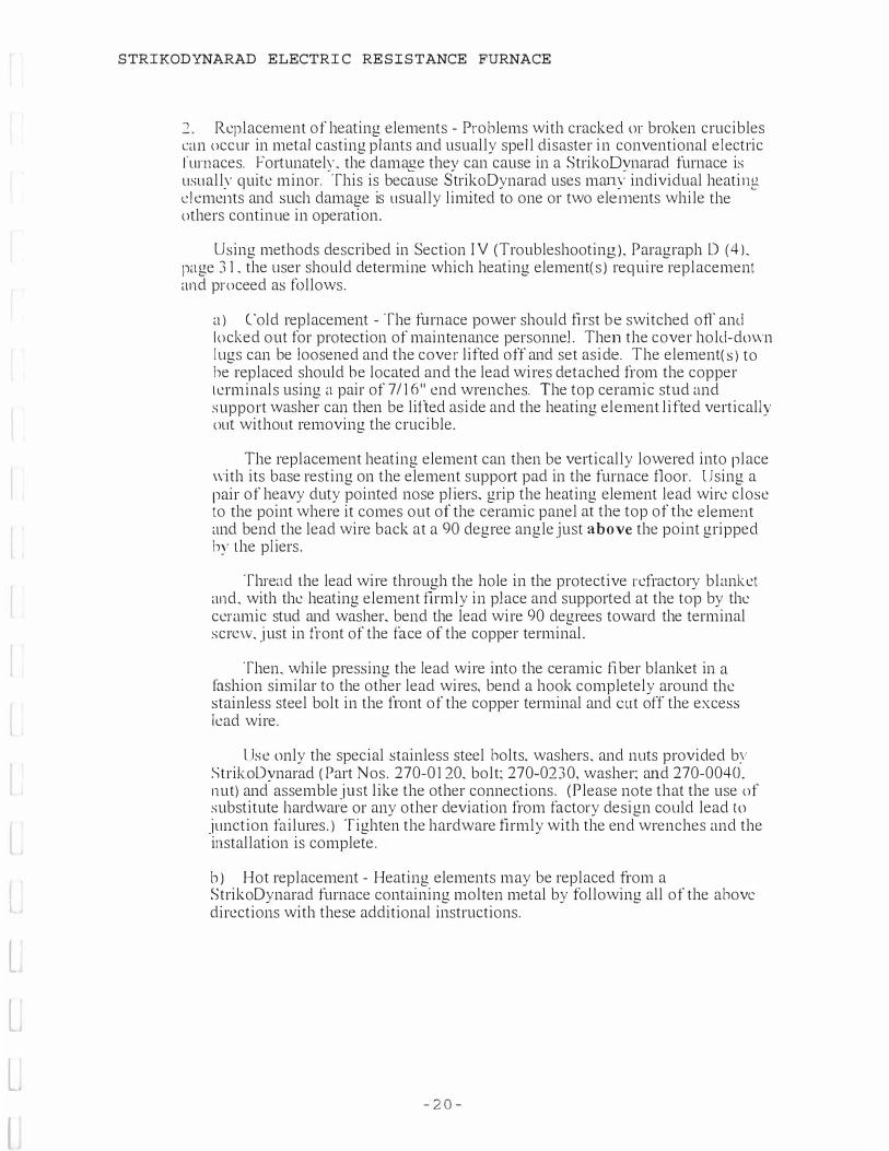
' Replacement of heating elements - Problems with cracked or broken crucibles can occur in metal casting plants and usually spell disaster in conventional electric !'urnaces. Fortunatelv. the damage thev can cause in a StrikoDvnarad furnace is usuallv quite minor. ·This is because StrikoDynarad uses mam; individual heatirn2. clemei1ts and such damage is usually limited to one or two elei11ents while the others continue in operation. Using methods described in Section IV (Troubleshooting). Paragraph D ( 4 ). page 3 1. the user should determine which heating element(s) require replacement and proceed as follows. a ) Cold replacement - The furnace power should first be switched off and locked out for protection of maintenance personnel. Then the cover hold-down I ugs can be loosened and the cover lifted off and set aside. The element( s ) to he replaced should he located and the lead wires detached from the copper terminals using a pair of 7 / 16" end wrenches. The top ceramic stud and support washer can then be lifted aside and the heating element lifted vertically out without removing the crucible. The replacement heating element can then be vertically lowered into place with its base resting on the element support pad in the furnace floor. Using a pair of heavy duty pointed nose pliers. grip the heating element lead wire close to the point where it comes out of the ceramic panel at the top of the element and bend the lead wire back at a 90 degree angle just above the point gripped hy the pliers. Thread the lead wire through the hole in the protective refractory blanket and. with the heating element firmly in place and supported at the top by the ceramic stud and washer. bend the lead wire 90 degrees toward the terminal screvv. just in front of the face of the copper terminal. Then. while pressing the lead wire into the ceramic fiber blanket in a fashion similar to the other lead wires, bend a hook completely around the stainless steel bolt in the fi:ont of the copper terminal and cut off the excess lead wire. l Jse only the special stainless steel bolts. washers. and nuts provided by Strik.oDvnarad (Part Nos. 270-0120. bolt: 270-0230, washer: and 270-0040. nut) and-assemble just like the other connections. (Please note that the use of substitute hardware or any other deviation from factory design could lead to junction failures. ) Tighten the hardware firmly with the end wrenches and the installation is complete. b) Hot replacement - Heating elements may be replaced from a StrikoDynarad furnace containing molten metal by following all of the above directions with these additional instructions.
- 2 0 -

l
l
L.
L
l
INS TRUCTION MANUAL
Equip personnel with high temperature gloves and protective insulating clothing. When the furnace cover is removed. place the crucible cover or a suitable piece of ceramic fiber board or blanket over the crucible and lay a two foot wide. five foot long strip of high temperature ceramic fiber blanket ( StrikoDynarad Part No. 520-0010) over the gap between the heating elements and the crucible to eliminate glare and heat radiation from this area. Additional strips may be used to cover this gap all around the furnace to minimize the overall tempera- ture loss during the element change. Using high temperature gloves and the tools described above. the element(s) can be quickly replaced. One element should be replaced in about one-half hour. D. Tightening Electrical Connections All conductors of electric current such as cables. connectors. terminals. etc. generate a small amount of heat which. in turn. causes these conductors to expand and conttact. This expansion and contraction can cause electrical junctions and connections to loosen. In addition. vibration during shipment can also loosen electrical connections. Loose electrical connections are highly undesirable because they increase the resistance to current flow. generating hot spots at loose _joints which can damage or destroy the connectors and any components to which they are connected such as contactors. fuse blocks. terminal blocks. etc. To avoid electrical hot spots. StrikoDynarad recommends the user regularly turn off and lock out all electrical power and tighten all electrical connections at the power source. inside the control panel. and in the fornace junction box. This should be done immediately after the furnace is put in service (to catch any loose junctions caused by shipping vibration) and thereafter on a quarterly basis. A "tug test" consisting of pulling firmly on the attached wire or cable to check for looseness should be performed after tightening each junction. Regularly t ightening electrical connections is a sound maintenance practice for all electrical equipment including electric furnaces which will pay dividends in time and money saved. IV TROUBLESHOOTING A Control Panel Electrical Safety 1 . DANGER - HIGH VOLTAGE! - Turn power off before opening the Control Panel door. The fused disconnect switch or circuit breaker which supplies power to the Control Panel should always be opened and locked out before opening the ( \mtrol Panel door and particularly before performing any maintenance work inside the panel. ' Do not rely on the door switch - While the Control Panel is equipped vvith a safety door switch which opens all high voltage contactors and shuts off all low rnltage ( 120 V AC) control power. it is still possible to sustain dangerous and potentially lethal electrical shock if personnel should touch any terminals behind the protective barrier. or if the barrier should be removed and not replaced. or if any components such as contactors should become defective and remain closed when they are turned off and expected to be open. Don't rely on the door switch ! Shut off and lock out incoming power before opening the Control Panel door.
- 2 1-

l
l
L
L
STRIKODYNARAD ELECTRIC RESISTANCE FURNACE
I � . Thermocouples 1 . Metal Bath Thermocouple a) Thermocouple failure - If the bath thermocouple protection tube is worn out or damaged. molten metal can enter the tube and damage the thermocouple element. This usually results in an open circuit condition which drives the bath pyrometer temperature indicator to the maximum or full upscale position causing the pyrometer to turn off power to the furnace. However_ if any metal leakage through the protection tube is slow and gradual. the thermocouple element may not immediately go into an open circuit condition but instead. may degrade slowly and provide an incorrect millivolt output (usually a low output). The bath pyrometer will then give an incorrect reading which can be checked with a separate (perhaps a portable) temperature sensing instrument. ,\ bath thermocouple short circuit condition. usually caused by a loose connection somewhere in the thermocouple or lead wire circuit will result in the pyrometer driving to the low end of the scale which will call for power to the furnace. This can result in overheating of the bath with the highest temperature ultimately determined by the setting of the Element Temperature Limiter. Thus. care must be taken to avoid short circuits in thermocouples or lead wires. b) Replacement - A defective thermocouple should be replaced. Refer to Section III (Furnace Maintenance). Paragraph B (2). page 22. for thermocouple replacement instructions. Element temperature limit thermocouple a) Thermocouple failure - The element temperature limit thermocouple is not subject to constant submersion in molten metal so this is not a normal cause of failure. However. the element will slowly deteriorate as a result of time and temperature and will eventually fail. usually by an open circuit. b) Result of failure - An open circuit thermocouple failure will result in the clement temperature limit pyrometer indicator being driven fully upscale vvhich will turn off power to the furnace. This could result in a freezeup of the metal bath if the furnace is not supervised. c) Replacement - A defective thermocouple should be replaced. Refer to Section III (Furnace Maintenance). Paragraph B (3 & 4), page 23. for thermocouple replacement instructions.
- 2 2 -

l
l
INSTRUCTION MANUAL
C • . 1\larms I . Ground Fault Alarm a) Description of operation - The Ground Fault Interrupter (GFI) senses current flow into and out of the furnace. If inflowing current above the C iFI's set sensitivity adjustment finds a path to ground instead of returning through the normal supply cables. the GFI will detect the fault to ground and instantly shut off power to the furnace. sound the alarm and light the "Ground Fault" lamp. However. the GFI is designed to ignore very low level leakage currents. which are normal. to avoid nuisance tripping. b ) Possible causes - Any ground fault above the GFI's low level minimum sensitivity (which is adjustable. but factory set at the most sensitive setting l which occurs anywhere in the furnace power circuits beyond the GFI sensor (located inside the furnace pull box) can trip the GFI. For example. metal leakage from the crucible of sufficient quantity to complete a path from the metal bath to a heating element should cause the ( ; FI lo trip. Thus the isostatically pressed silicon carbide bath thermocouple protection tube must always be tightly clamped in its U-bolt clamp with its l)() degree union similarly tight to adequately ground the metal bath so that the C ; Fl can operate properly. Similarly. any other such path to ground caused by any metallic object contacting any current carrying cable or component in the furnace should trip the GFI. c) Reset - Open the Control Panel door and locate the ground fault relay inside the panel. Switch the white circuit breaker lever upward to the reset position. If the fault is clear. this will silence the alarm. d ) Find the cause - lf the GFI successfully resets. the furnace should be closely inspected for the cause of the original trip. For example. the rune.mt port should be inspected for evidence of dripping metal which might have resulted in a GFI trip. If the GFI will not reset. the fault has not been cleared and the furnace must be shut off and checked for the cause of the ground fault. Use the following procedure : I ) Be sure the ground fault relay sensitivity adjustment has not been left in the "test" position which would cause continuous tripping. Refer to page I 0. paragraph 5 for directions on how to check this. 2) Open the main disconnect and check inside the control panel and the li.mmce terminal box to be sure that the neutral terminal has not been connected to ground. If it has, remove this ground connection.
- 2 3 -

l
t
l
l
(
STRIKODYNARAD ELECTRIC RESISTANCE FURNACE
3 ) With all povver off remove all of the heating element fuses and disconnect the neutral lead going to the furnace at the _junction terminal inside the control panel. Then close the door and restore power and see if the ground fault relay trips. If it does. the ground fault relay or sensor is causing the problem. 4 ) If the ground fault doesn't trip. the fault is somewhere "downstream" of the heating element fuses. To find it. connect one lead of an ohmmeter to LJ:round and touch the other lead to each of the lower fuse terminals vvhere the wires going to the heating elements in the furnace are connected. Also touch this ohmmeter lead wire to the neutral lead going to the furnace which you _just removed. 1 r you find resistance ranging from a dead short to several thousand ohms between any of these wires and ground you have found the ground fault. Trace it out and locate the exact point of the fault which could be in the wiring going to the furnace or somewhere inside the furnace. perhaps caused by a recent metal spill. When the fault is cleared. you're back in business. NOTE: A new furnace which has been operated less than two or three weeks or an older furnace which has been placed back into service a fter several months of inoperation may contain moisture which can register resistance readings. usually in excess of ten thousand ohms. which is normally insufficient to trip the ground fault. Resistance readings caused by moisture also tend to give "erratic" readings which seem to constantly change. These readings will increase up to the megohm and higher range. effectively disappearing. after the furnace dries out fully. Should GFI tripping continue without obvious cause. the user should contact StrikoDynarad's Service Department for assistance. 2. lligh temperature limit - The element temperature limit pyrometer is equipped ,vith a second high temperature alarm setpoint which actuates approximately I 25°f;1bove the normal adjustable high limit setpoint (which should not be set above :2000°F). If actuated. this high temperature alarm will open the power contactor. sound the alarm. and light the red "Element Over Temp" lamp. Should this alarm be tripped. the user should shut off power to the furnace and permit it to cool down below the normal high limit setpoint and then investigate the cause of the alarm and correct the problem.
D. Heating elements 1. Using ammeters to monitor the heating elements a) Introduction - This StrikoDynarad furnace is equipped with ammeters ,v-hich continuously indicate current flow to the heating elements. These ammeters provide helpful information about the condition and performance of the heating elements. - 2 4 -

l
l
l
L
(
INSTRUCTION MANUAL
b) Independent readings - Each ammeter independently reads the current in .i ust one phase regardless of furnace voltage or whether the furnace is wired in a "delta" or "wye" configuration. c) Element grouping - A group of elements is wired across each phase. the exact number depending on the size of the furnace. I n some furnace models the number of elements in each group may vary. but never by more than one dcment. Thus. all meters will read close to each other but may not read exactly the same. d) Separately fused - Each heating element is separately wired and individually fused. Heating element fuse blocks are located inside the Control Panel. The Control Panel should never be opened without shutting off all power to the furnace. e) Determine elements per group - The user should refer to the electrical schematic diagram for his particular StrikoDynarad furnace model and determine the number of heating elements connected in each phase group. Then he can divide the number of elements in each group into the ammeter reading for that group to determine the current flowing through each individual hcatin!! element. This information will be useful for check.in� elements following instructions in Paragraph 3 below. �
' Normal current variations a) Voltage fluctuations - Most electric utilities are obligated to maintain their customers' voltage to no better than plus or minus five percent of the nominal supply voltage. Since the current flow to the heating elements is proportional lo the supply voltage, ammeter readings can vary by this amount as well. The supply voltage normally follows grid wide as well as local demand patterns. It will drop during periods of heavy use and rise during off-peak periods. h) New elements - When StrikoDynarad heating elements are brought to fu ll operating temperature for the first time. aluminum in the resistance alloy oxidizes at the surface. forming a protective coating of aluminum oxide. This effectively stops further oxidation and gives StrikoDynarad heating elements a decided advantage over other types, such as nickel/chrome elements. which form no protective coating and continuously oxidize until they are no longer useful. When StrikoDynarad elements form this protective oxide coating. the dectric resistance rises slightly causing the current to drop slightly. Then the resistance remains relatively constant throughout the operating life of the element. c) Temperature changes - As with most resistance heating alloys. the clements will draw slightly more current when the furnace is cold than when it has reached operating temperature. This is normal.
- 2 5 -

l
(
STRIKODYNARAD ELECTRIC RESISTANCE FURNACE
3 . 1\bnorn1al an1111eter readings a) Element out of circuit - If the current reading of any ammeter should drop hy an amount equal to the current required for a single heating element. then one element is out of the circuit for that group. A current change of this type can be distinguished from a normal voltage fluctuation by noting that the change is larger than most normal fluctuations and appears in just one meter while voltage fluctuations usually affect all three phases at once. b) Causes - An individual heating element can drop out of the circuit because of an open fuse. an open wire or junction. or an open heating element. ..J.. Checking individual element circuits. The follO\ving procedure may he used to troubleshoot heating element circuits. a) Shut off all power to the furnace. Lock out the breaker or disconnect to be safe. However. it will not be necessary to empty the furnace since the checking procedure can be completed quickly. b) Open the Control Panel and remove all fuses from the element fuse blocks. (It will not be necessary to remove the two fuses which protect the step-down transformer which provides low voltage instrument power.) c) Use a continuitv checker or ohmmeter to check the fuses. Ir any are open. obtain replacement; of the same size and rating. d) Re fer to the electrical schematic and determine whether the furnace is '\.vye" or "delta" connected. Most 480 volt furnaces are wye connected and the return leads of all heating elements are connected to "neutral". Most 240 and 208 volt furnaces are delta connected and the return leads of the heating elements are connected to the incoming three phase power legs designated "A". "13". and "C". Referring to the connection lugs on the main contactor and the heatirn2: dernent retm;1 terminals to the lefl:�of the element fuse blocks. the left lu!.! �ff terminal is leg ":\". the center lug or terminal is leg "B". and the right lug or terminal is leg "C". e) Checking "wye" connected furnaces - Connect one probe of an ohmmeter to the furnace neutral terminal. This will be the red colored stand-off insulator terminal to the left of heating element fuse blocks. Then. with the fuses still out of the fuse blocks. measure the e lectrical resistance of each heatin!.! element by contacting the other ohmmeter probe in turn to each of the lower fi3se block terminals.
- 2, 6 -

{
l
l
l
INSTRUCTION MANUAL
All elements should read approximately the same resistance (this resistance will depend on the furnace operating voltage). If any circuits are open (the ohmmeter reads infinity) or read much lower than the others ( including a direct short). note the element number for later checking. Ir all elements read approximately the same resistance. and a fuse was previously found to be open. the problem is the fuse. Replace it and place the 1·urnace back in operation. I') Checking "delta" connected furnaces - Note that each fuse is labeled with a number followed by two phase leg designation letters separated with a slash mark. For example. a fuse might be labeled. "3 CIA." To check each element first connect one probe of an ohmmeter to the appropriate furnace return terminal lug (to the left of the heating clement ti.1sc blocks) corresponding with the second letter on the fuse label. (Remember. the left lug is "A". center lug is "B". and right lug is "C".) Then connect the other ohmmeter probe to the lower terminal of that fose holder and read the clement resistance. Similarly. determine the resistance of each of the other heating elements. carcfolly following the above procedure. Just like the "wye" connected rurnace. all elements should read approximately the same resistance (this resistance will depend on the furnace voltage). If any circuits are open (the ohmmeter reads infinity) or read much lower than the others (including a direct short). note the e lement number. If all elements read approximately the same resistance. and a fuse was previously found to be open. the problem is the fuse. Replace it and place the fi.1rnace back in operation. :'i. I r any of the heating element resistance readings show an open circuit (the ohmmeter reads infinity). or if they are much lower or even a direct short the i"urnace must be opened and the element(s) checked. However. it is not necessary to do so immediately. If the user would prefer to check the element(s) later, all fuses may be replaced except those which protect the clement circuits in question and the furnace may be placed back in operation. The clement(s) can then be checked at the convenience of the user. 6. Element numbering system - Looking down at the furnace in plan view·. the he,1tirn1: elements arc numbered in consecutive clockwise order starting with the clement closest to the element protection thermocouple. These numbers correspond \\·ith the numbers shown on the individual element fose holders. 7. Replacement of heating elements - roll ow the instructions in Section III ( Furnace Maintenance). Paragraph C (2).
- 2 7 -

l
l
l
L
L
STRIKODYNARAD ELECTRIC RESISTANCE FURNACE
E. Temperature Control Instruments I . Fine Tuning - The bath thermocouple pyrometer may require "fine tuning" acl_justment(s) of the Reset Rate. Proportional Band. or Load Line settings to improve temperature control performance in a particular instal- lation. The element temperature limit pyrometer requires no internal adjustment. ' Refer to manuals - Please refer to the individual operating and servicing manuals for "fine tuning" or other information concerning the pyrometer instruments which are found in the Appendix at the back of this manual.
- 28-

L
l
l
,,
STRIKODYNARAD ELECTRIC RESISTANCE FURNACE
V REPLACEMENT PARTS LIST - MODEL EC- 1500 Following is a partial list of replacement parts for your StrikoDynarad furnace. Please contact the factory for any parts which are not found on this list. DESCRIPTION PART NO. THERMOCOUPLES & ACCESSORIES � Bath thermocouple assembly. complete 24" Bath thermocouple protection tube 24" . .eBath thermocouple element 24" hot side High Limit TIC Element Assy. 12" REFRACTORIES & CERAMIC COMPONENTS Blanket 1/2" thick ceramic fiber Blanket I" thick ceramic fiber Blanket 2" thick ceramic fiber Patching cement for floor. castable. 75-lb bag Ceramic studs 2 1/2" Ceramic pink washer
140-0012 520-0030 520-001 0 520-0035 50 1-0010 530-0020 530-00 1 0
HEATING ELEMENTS \ i-.t Type E. 28". 277 volt ) � \� - �O \ ,....,. �� 1 � ' MISC. FURNACE COMPONENTS I-lat Ring Element Terminal Assy. EC-Series 103-0025 1-l igh Temp Stand-off Assy. 103-01 00RP Pedestal Size Seperation disk-one size. customer cut to pedestal size 530-013 8RP Wire Harness Heating Element Restraint Replacement Assy. (Heater Hanger) 320-2110 INSTRUMENTS. REL\ YS & MISC. Bath Controller. Honeywell UDC 3000 High-Limit controller. Honeywell UDC 2000 Relay. Contactor Control Fuses ATM 30
350- 1 1 1 5 350- 1 150 320- 1 120 360-5230

l
l
l
l
l
STRIKODYNARAD ELECTRIC RESISTANCE FURNACE
VI INDEX Alarms 2 1 -22 Ammeters. reading 29.3 1 Argon degassing 16- 1 8 Batch melting. pyrometer settinQs 1 1 Batch 1;1clting. maximizing utilization 13- 14 Bath pyrometer. setting I I Charge material. drying 12 Chlorine. use of 18 Connections. tightening 25 Continuous melting. maximizing melt rate l 0 pyrometer settings I I C�ontrol PaneL n1ounting 3 wmncr 4-5 safctvc 26 Cover: furnace. proper seal in!! 6-7 ( ·over. 1-1neumatic 7 Crucible cover 1 3 Crucible cracks I 7 dimensions 5 double glazing 5 filling at night 13 gasket 8. 15 inspection 17 installing 6 overfilling 1 7 replacement 6. 7 scraping 16 sling 6 Crucible separation disk 7. 22 Current fluctuations 30 Delta connection current readings 8 Demand control 15 Drying charge material 12 Electric resistance. heatin!! elements 29-33 Electric'al connections. t id1tcnin!2. 25 l�l�ctrical ::Viring check 6 Explosion hazard 12 First melt I 0- 1 I
- 3 0 -
Fluctuations. voltage 30 current 3 0 Fluxes 17-20 definition 1 7 non-reactive 17. 19 reactive 17-20 tablet 17. 1 9 Fork channels. furnace 4 Freon degassing 17. 19 Furnace cover. proper sealing 7-8 Fuse. open 3 1. 33 fuses 29-33 Granular fluxes I 9 Ground fault interrupter 1 0. 27-28 Ground. furnace 5 Heating elements 23-24 checking 3 1 designation 32-33 groupmg 30 new. current readinQs 30 numbering 33 over temperature alarm 25 oxide coating 24 proper lifting 4 replacement. cold replacement. hot rubber padding temperature change. effect 30 temperature limit. 22 2 1 ,., _)
settinQ 8. 1 0- 1 3 . 25-26 Holding: off shift l 6 production 16- 1 7 Main switch. installing 5 Melt rate. maximizing l 0 Metal leakage. thermo-couple 22 Moisture danger I 0 Nitrogen degassing 16-18 Overshoot, temperature 15 Oxidation. heating elements 24 Packing. styrofoam 3 Padding. elements. rubber 3 Phase designation 25-26

l
l
l
l
VI INDEX (continued) Pit installation 4 Pneumatic cover () Power failure 20 Po\\er level switch 9. 1 5 Protection tube. bath thermocouple 8. 22-23 Protective coating. heatinf2: clements 30-3 1 Pyrometer settings 9. 1 1 . 33 element temperature limit setting ()_ 1 3. 1 4. 28 Runout membrane 22 Runout pan 4 Salt fluxes 1 7-20 Seven day timer 1 1 . 20 Shutdown 20 Steam. startup 1 2 Tablet degassers 1 7. 1 9 Temperature control 1 3- 1 6. 33 Temperature overshoot 1 5 Testing. electrical 5. ')- 1 0. 3 1 -33 Thermocouple installing. bath 8 conduit 5 connections 5-6 failure 26-27 lead wires 5-6 metal leak.acre 26 open circuit�ondition 27 polarity 5 . 9 . 23 short circuit condition 26-27 replacement 8. 22-23 speci f'ying: 8. 22-23 Thermocouple. bath. { I-bolt clamp 8. 22 Tie:htenini! connections 25 Ti�1er. se;en day 1 1 - 1 2. 20 Utilization. furnace I 4 VoltaLl.e fluctuations 30 Wve ;onnection. current r�ading:s 9
- 3 1 -

r-·
\
HIGH -TEMP
CERAMIC
STAND-OFF
WIRE __J
HARNESS
RUN -OUT PORT
NOTICE
ln• doc.- is tr-eel ,oieiy fo, the pu,poN "' aang the tr-lion cl bu-- l>atCMWWl CORP. - - � - - be r.tumed on �- ,.. drowir>9a, inlormotion ond doto inck"""i ol � - � cont......S t>er-aon c:n the .,.--ty of O'l'KAIVD CORP. -ffiOy � be � ,,, coi>ied in - « in � nor oppr-opriGted to uM{s) in Otty --, � to the -• ct D..-..0 CIJflf'. including d;.do-...-. t.o out...i. po,tin, directly o, indirktly, nor con it be - f« the .......,oc:t..-. "' .,,,, ......-,t � ,cribe(I �t the �ic ,.;tt-, con...t ct IMWW> CORP.
DYNARAD TEl...£PHONE: (510) 638-2000
FAX: (510) 639--4�
FURNACE COVER
INSULATION
CRUCIBLE
I N S U L A T I O N D E T A I L S E C F U R N A C E S
FURNACE COVER
PLATE
--2" GASKET
INSULATION
H EATING ELEMENT
GRADED FURNACE INSULATION
( 1 : 10 )
A0132 FILE: A0132A-l.D\JG

[
[
l
l
l
VI I NDEX (continued) Pit installation 4 Pneumatic cover 6 Power failure 20 Pmvcr level switch 9. 1 5 Protection tube. bath thermocouple 8. 22-23 Protective coating. heating elements 30-3 1 Pyrometer settings 9. 1 1 . 33 element temperature l imit. setting <)_ 1 3. 1 4. 28 Runout membrane '' Runout pan 4 Salt !luxes 1 7-20 Seven dav timer 1 I . 20 Shutc.fow�1 20 Steam. startup 1 2 Tablet degassers 1 7. 1 9 Temperature control 1 3- 1 6. 33 Temperature overshoot 1 5 Testing. electrical 5 . 9- 1 0. 3 1 -33 Thermocouple installing. bath 8 conduit 5 connections 5-6 failure 26-27 lead wires 5-6 metal leakage 26 open circuit condition 27 polarity 5. 9. 23 short circuit condition 26-27 replacement 8. 22-23 specifying 8. 22-23 Thermocouple. bath. l J -bolt clamp 8. 22 Ti !!htcnin!! connections 25 Ti�1er. se;en day 1 1 - 1 2. 20 Utilization. furnace 1 4 Voltage fluctuations 30 Wve connection. current r�adings 9
- 3 1 -

,--- ,---
r�:==::i i : : !
i : L� SUPf'ORT MO.( <RE,.,
2
-
t,,,,,J n t �
·-�� �¼ \_ 1£AT(lt L(AD <1t£F.l
·\/IRE LUG ON '--{ 11 \IJRING HARl<SS <R(F.)
EDIT EDIT EDITIEDIT REV I ZONE DESCRIPTlON BY I Do>,T(
TOLERANCES: UNLESS OTHE:R'MSE SPEClflED
�·f mY l:a --.a "'
Olhl(t(S)()NS � 1K INO£S
NOTlC£ ................... ...., .... .. ..,,... �:.��---=--.,_... _ .....-L · ---- ---- -............................ ..-.-.
.. 'lfA STRIKO -::: . .• DYNARAD
TEl...E?tiONE (510) 638-2000
FAX (5 I 0) 639-�5&4-
ELECTRICAL STAND-OFF
........ �-�UR'. ... --- - ----- -- - ---- ------ - .. - ., -.. "' - ., " - --DHT """' 1-20-98 OR»l'ING NO. REV. = � r::.=->cn:..·:.::.::=- - 1 _ .. _ _ _____ � ... """' AO 68 . .. ... .. .. ......._.. _ .., .........
:.0"":_- - - - • =.,: """-' 4 / 7 A0168A-l.D\JG SHcrr l or
A
l

ELECTRIC STANDOl"F ASSEMDL Y & IIARDW ARE
FOR CONNECTING TI IE STANDOFF TO TIIE HEATING ELEM ENT
r - ---l--( SIPPOIII N«il.C (R[r.>
____ fl_ ____ �---·tl·-·-·-·-·-�-- �'-©
'•--\ I I
\_ 1-l[l\l[lt L[AD (R(r.>
VfRt LUG Cl'f VIRl'fti HMNCU (RE.r .J
The sla11Joff assemb.ly is used as a connection between the wire harness and the healing cl�ment.
The Part Number is 103-0J00RI' and may be purchased as an assembly 011ly. II consists o[
Q) Stainless steel screw, ¼ x 2¼", 1 8-8 stainless steel. (Z) Female cup bushing, ceramic standoff 0) Shoulder bushing, ceramic standoff ® Duss bar, copper clip assembly (J) Hex. nut, 1 0-32, 1 8-8 stainless steel <ID Flat washer, # I O 1 8-8 stainless steel ® Lock washer # I O stainless steel
��)J 0
\..........
11,e l,ard"'are assembly used to connect the heating element to the stan<lon: is made up of the remaining drawing numbers on the diagram below.
The Part Number 1.70-0J27. lt is supplied as part oflhe replacement heating element, but may be purchased separately as an assembly. It consists of:
� Hex bolt, ¼-20 x I " 4 1 0 or 430 stainless steel. (G) Hex nut, ¼-20 304 stainless steel. (9) Flat washer ¼ x. 1 1 / l 6 304 stainless steel 1 1 . Flat washer ¼ x 7/8 304 stainless steel

r- r-_, __
------- 02 -------;
BATH THERMOCOUPLE
ELECTRICAL PULL BOX
POWER CON TROLS
!OYNARAO! 1 r.::::::ir::=.::,r:;:;:-:::, ���
� 83 � 36" El
0 1 F---30" �
1 2"
IQ.._
I ..1. I
DIMENSION TABLE MODEL D, D2 P, P2
EC- 600 1 87T 46" 1 2" 1 2"
EC-700 21 ' 51" 1 2" 1 2" EC-950 27" 56' 1 8" 1 2" EC- 1 1 00 31" 63" 1 8 .. 1 2" EC-1 500 34" 53- 1 8' 1 2" EC-2400 37½ " 72" 1 8" 1 2"
NOTE: RUN-OUT PORT MAY BE LOCATED IN ANY OF THREE POSITIONS RELATIVE TO ELECTRICAL PULL BOX.. CONFIGURATION "A" SHOWN. PLEASE SPECIFY.
I O'YNARA0 I
42" [□ TYPE "A"
� P2 �
FORK LI FT ACCESS
CRUCIBLE MAKE g. MODEL: __ _ _ _ _ _ _ __________________ _
SUPPLY VCLTAGE: _ _ _______ VOL TS, __ _ _ _ _ _ _ HERT Z ,
v: TH O O R O 'w'I)HDUT NEUTRAL
START -UP SERVICE REQUIRED'? YES O NO 0 SHIP VIA '?
ELEMENT PROTECTION THERMOCOUPLE
EMERGENCY R U N - OU T PORT
-•STRIKO -.: DYNARAD
,� ..,,,..,_, StrTn,, S... L...--0. CA ,.,77 T- c:11� r ... C,llll�---
Thte docMfflenl ia trOl'l""'ltled _.., fo, the � ol oldl,,g lhe ,,..,_,Ian of to,..,_ bel- STRIKOO'l1'NIAD ond lh• rcip..-it en- mu■l be ral\1.med Ql"t requel. AM drowlgs. wtlormollan ... d clato Mtud� .. dal<!n• ... d can-I• ..,,.loi,,ed ,__ are Ille -ty ol STRIKO OYIIAlll,Q Oftd moy not N f"tlllll'OdUcad r,t CIIO.ed irl .,..ol• or lfl pearl nor �ted lo uN(1) i,, .,., _, detnm .. toi lo lh• .,,_ta ol STRIKO OYMAAAO lndudlflg died.,.,,_ lo outalclll pcwll-. dlNc.Uy r, 1"d�U-,. "°' COi' ll tM uNd far lhe rnant.tfact.ure al any -,.,ipm-,t ._,.ibed withaul lh• IDeeiflc •ill., c:an_,t of ST'RIKO OYNAAAO • .
EC SERIES ELECTRIC RESISTANCE
WELTING FURNACES
-coos1 If· Flt.£: cooa,r-1.owc
SHEET 1 OF 1

l
L
L·
L
l
StrikoDynarad
ALUMINUM AND WATER VAPOR
The origin of aluminum oxide and hydrogen gas is often misunderstood. Too often burner or
fuel fired furnace manufacturers would have us believe that their "advanced technology" has
solved the problems of dross and hydrogen gas contamination.
Although we agree that properly designed and operated fuel fired equipment can keep
contamination to a minimum, it also must be noted that certain laws of physics cannot be
altered or designed around. The following technical data is to inform you of the problems
inherent in fuel fired furnaces due to the by-products of combustion. More complete data is
available upon request.
With this information in mind, it is easy to understand the distinct advantages of electric
melting and the way in which it helps to insure reduced melting costs and a cleaner, purer melt.
Please refer to enclosed exerts from the Aluminum Casting Alloys Handbook and Casting
Kaiser Aluminum.
F:\sales\sales aids\al and water vapor

CAS'flNG l(Al�Elt ALUMINU1'1
l'ii; anJ Iugot l'roJuct Dal•
C1111i11g l'rnctlce■ and C.l1aroclcri■tle1 of nloltcn Aluminum
nnsr EDITION
KAIStn ALVlllHVll A CIIOIICAL IALU, IHC.
IHl1 North Mlchl1•n Annul Chlciigo 11, llllnolJ

1 .
Tho mere µnrncuce o{ tllseolvctl a11.s i n l h e mollcn mcln l t.loes 1 1ol 11ecess11rily menn lhnl hnrm{ul poro11lly w l l l appcnr 1 1 1 l l i o cn1 l i 1 111, Unt.l cr cu1 1d i liu1111 or rup l tl 1111 l i t l l l lcnllon, ,wch 1111 IH fou1 1 LI 1 1 1 1 1 1ir1 1 1 1 1 1 101 1l 1 1 1 1 1 1d 1·1 1: tl i 1 1 1:, I lw i l i:1:11,h·,·d �:11111•11 11111.v 1 1 1 • t l i:qwnwd i 1 1 1 1 1 1 1 :h II l i 1rnl.v d l v ldt:d 11l.11I.P 1.1 1 1 1 I. 1.111 •.v c11 1 1 1 1ol 1111 11i1Hu1°vu1l v il(1t11 l l y 11 1 1 t l i 1 1 w l t it: lt l lwy 1 10 1 1ol nlfccl 11 1 lv1!rHuly lhu 11rc1111 u ro-lluhl 1 1c1111 of the cnsl ing . Their presence, ltow11nw. rnny hnvc l'omo oITccl on lower ing lhc 1 1 1echu11 ic1 1 I prnperl i1!11 of l.111• 1·:1111i111r. parlic11l11rly d11l'.l i l l l.y 1 1 1ul lrnp:1cl 11lrc11ic lh . The :rnfc/\l prncl.ir.n i" to hnvo, a11 nearly n:1 po11Riulc, n gos-free mcln l Lefore cnsl lng.
T�1e -�e�ontl_ J_��lalne the mechanism by�<:.!!__g_nscs -�-t_� a_�sorl.,1:_d . .9_� rctJuclng gase1 f are dlssolvecl In mollen n luml 11 u m._'l'ltc oxygen In oxidi zing gases forms oxide compounds which J>_!Cc�pi lnlo out a11t.l e l lher flont In the melt ·or rise lo the 11urfncc, t..lcpent.llng 011
lhelr-aiJ'edficgriwlty relative to the melt. 'l'o repent, unless n reuucl1 1g gas ls"ln-conlRct with the molten metal, none of tho irns wl lr1o<lls-110lvct1:·wntor vnpor mu11l ho con11hiorctl In the cntcgory orrc<luclng ·gases· sl nee 71ls-decomposed lnlo hydrogen Rn<l oxygen wli en l l comcR 1,iCoconliicfwilh mollen l\tumlnum,
AllhouK'h a n umuer ol reducing gases may uc present i n the furnace almosphere, dcpentllnr on lhe na ture o! l h c fue l nn t l co11 1uusl ion contlillons, hydrogen is the gas mosl rcatJily nbsorl.,ctJ. I l Curlher nµpcnrs that the grenlesl amount ol gos absorption occurs when l 1 1 e hyt..lrogc11 Is In the Cree or nascent ala� (hydrogen protlucet.1 uy some l'eacllon in the v ic in i ty ol the molten n luml num) .
EFFECT O F M O I STI.__J R E
When waler vapor 111 decomposed li te hydroge11 that fo pro<lucctl Is In iiie nnscent or active stale. It follows lhal\vatcr, wnler vopor or nny form o{ moisture nre very likely causes o{ gns nusorpl1011 nnu j)oros"fty Ill cns tin!l','I, I t I s lherel�re Impera tive lokeep lo n i i i lniniurli the amount ol moisture comlnr Info coilTicCwiU,-i11·01 l'en-n lu 11 1 i iiuil1. ,fiioThe·rs·o-urce on11drogen Is luel llsc1f.7Cr1111_y_ co1i lain-J i yd i·oiielll\·s one o{ i ts components or may be composctJ o{ hyt.lrocnrLons wh ich i n l h c process o ! cornl.,usllon are converted Into wn ler vnpor.
l l is commonly M1:1umed lhat In crucll.,le or open pot 111 e l l i 11 g 110
�!.!_ger exlRtR from g1111 nl.,sorptlon becnuRo lhr. tlnmo does not come l��conl�ct with tho molten ·metal. This nssump_�!�!.!_!�_fR l.�:�ses_ con d ifTuso very rendily lhrouirh a refrnclory crucible, nncJ I t hns Riso £,'cc1i11i:11v·ciltl111t. 11:t:-ICt!lll hydro run CIIII pcnulrnlc li10\Villliicir11 c1111l •�neTflng pol. It shou ti e note thnt most Cu els cmifnTil7iy(li·oge1i �.IJ!xdr_<?_cnrbons, 11nd lh11t 11everal gallons of water in the form olvnpor nrc produced therefrom durlna- tho melt ing ol n hent of n lumlnum.
J\ 11 11lhcr 11011rcc of wnler vapor Is the n lr. I n open-pol me l t ing this i!! on i 1 1 1µorln1 1 l fnclor, s i nce the molten inclnl is n lwnys in cu11l11cl w i lh lhe 1:urrounr l lnu 11 l.rno.�rhr.ro. f:nri,l l llon!I n( hlid1 humlt.l i ly , l l r crcfurc, mny vcr.v wull cu11 l.ri l i 1 1 lt ! l11 1111 h1cru1111l! In poro:t i ly . ThlR 11111y 11ccou11t fur lhc fncl lhnl ll1 t l i11fncl11ry cnl\tlllgK nre produced one day nntl on the fol luwi1 1g dny l'cJecls are high, although there is no u ppare11l change in fuuntlry prucllcu.

CASTI N G A LLOYS
H A N D B O O K
F E D E R A T E D M E T A L S D I V I S I O N AMER ICAN SM ELTING A N D Rl!:FININO COMPANY
1ao ■AOAOWAY, Nll!:W YOnK "· NltW YOAK
COl"V,.IOHf " " ,101nA T I O MITAi.i OIVIIION, ,.,,u:,.,aAH eMII.TINCJ ANP nU'ININO coMrANV
our tltt•f II WAtt ti IHtv•• fHt attv11ac, "' tlft , . , ,. .... " ntut• "•""'"'' a1•1•, •"•llf• ,,. tmt uu,eaiun• •• uo ,...,, wc,wrv111 . auA ,u M r r t '"' lll! 1 t ,11. rt ro 1 1
OltAIHftl rttnW I M C lflU ,,, •111,- IHlf"• .. tllOJlf
I

Fi� :t-Seciioll or • Cut Part Showin.; roroaitr f'ou,blr Ca...-ed 'by Caa £....,lulion.
Dunn; Soticil!ic:alioa
Gas Porosity Thembl.c:n of controlling� in s lumioom
� C2Stin is e:it@v §ple on}y one g:u. bydr-ogc:n. u involved. ·ci.d the principal � of this ,:..S U moisture-• C
solubility of hydrogen in solid :uuminum is :um0$t nil. When the alloy melts, sohibility of tlie hydrogen incre::uc:s somcwh:lt :i.nd cootinucs to ino-e2se r.a.pidly with 2n inc:rc:i.sc in te:mpe:-:i.h.m!.. 'When a g--_s-cont:i.ming rnelt soudi5c:s too slowly, the dCO"C25-bg so1u'::lility of the hydrogen ousc:s it to prccipibte to form pi.::ihole::s, Fig. !, ;i.nd mic:-opcrosity. When the o:t.ide sl:in on :LU ::Llumin= melt is broken, the melt readily rea� with moistu..-e to form ;i.luminum oxide ::Lnd :i.tomic: or �cent hydrogen which :s a!J-=dy :i.c"..lve chcmiolly ::i.nd which is re:idily :md r.ipidly di::solved by the 2luminum melt.
Sou.recs o f Hy dro;;cn :rnd Mctuocls o f Avoidin� G:i.s Absorption
The !o-:.ndrpi:i.n should be :iw:ire of the sources of gas 2nd t�e l':lcthoc.s of ::i.voicing g:i.s :ibsorption. No dei;::i.�ing procedure m.-iy be rcq,ui:-ed in :ubscqucnt opcr.itions if g-::i.s :ibsorption is minimb:d :ind if i;::i.s porosi:-y is not :1 m:ijor bctor in determining :iccept.:i.blc c:u'..ing qu::i.li:-y. In die csting. the npid r.ite of cool-
7 0
bg reduces g:i.s porosit_:-'. However, g25 porosity xruty be � import=t factor in other � of ostings. The best v.';J.y to minim.� ur-.soundncs:s resulting from r;:i.s evolution is to combine the ,'"Uioc.s me:ins of -.voiding g:is 2-bsorption with sui::able subsequc:::it deg�g procedures desc:1oed in a �ter .sec!:ion.
Tile sourc=s of the � will provide the found.ryxr.:i.n 'With a l::ey to t.�e ,�ous me:u:JS whereby the a.bsorption of this gas c::i.n be m;nj::n:�ed It is difficult to rate the rel:itive impcrtance of these d.i.ff erc:nt sources of � becaase the conditions will vary cons:ide:rably from &y to 6y in the foundry. The following is a. desc::-iption of th� sources of moisture and hydrogeD and the methods of mi.ni..r:ni:in g hydrogen absorption from them.
Products of Coml:,ustion
cont:tin'
accom-"
in
Atmospheric Moisture
Mo�ture occurs n=itur:i.lly in tlie :i tmos-phere :ind ,-:tries from ::i fr:iction of :i gr:i.in per C\.lbic foot of ::iir in dry clim=itcs to 12 or 13 gr:iins per cubic foot in hot humid wc:ithcr. It is :i common CX?C---icnce th::it the problems of g:u unsoundne::s in .luminum c:utings incrc.-ise with the �bsolute humidity. This source of g:u is p:u-tiC\.ll:irly import�nt during the tr:msfc:r of aluminum rnclt.s or during :i.ny other mct::il h:mdling oper:ition in which the oxide lilm is broken :ind the mdt is permitted to cont:ict the �trnosphcrc. In :i given geo�phical loc1ity. tlie only means of avoid-
71
- ___, - _.

A StrikoWestofen Company

STANDARD
FEATURES
REPEAT ORDERS FROM DYNARAD USERS PROVE AGAIN AND AGAIN
DYNARAD® FURNACES
ARE THE MOST RELIABLE
MELTERS AVAILABLE TODAY!
LONG LIFE HEATING ELEMENTS
Dynarad® continuous duty, high temperature rated heating elements, with tens of thousands in service, are unsurpassed in operating life and reliability since first introduced in 1983. The durability and performance of Dynarad heating elements has never been equaled, an enviable record that enables Dynarad to back its elements with the industry's best warranty.
DAMAGE RESISTANT
PARALLEL ELEMENT WIRING
All heating elements in Dynarad furnaces are independently parallel wired and fused instead of series-connected like old style heating element arrays. With series wiring, if one element burns out, all elements in the series string immediately stop working. But if a Dynarad parallel wired element sustains damage, all others remain in operation! This common sense design gives Dynarad furnaces the highest up-time reliability in the industry.
"THERMOS BOTTLE"
MULTI-LAYERED LINING
Dynarad furnaces use a computer optimized, multi-layered lining
system designed with Dynarad's own custom software to cut heat losses like a thermos bottle. Old-fashioned monolithic refractories are eliminated to boost furnace efficiency and save energy dollars.
HEAVY DUTY CONSTRUCTION
Dynarad furnaces are built to handle the severe conditions often found in foundries and die casting plants. Features like extra heavy,
warp-proof plate steel furnace covers (3/4" for larger furnaces, ½" for smaller), heavy welded steel base and sidewall construction, and a rugged steel "hat" ring to protect the top of the crucible are standard on all Dynarad furnaces.
EASY INTERNAL ACCESS
The crucible and self-supporting, vertically installed heating elements are easily accessible by removing only the furnace cover. Side panel access is not required so Dynarad furnaces can be positioned close to casting equipment or other furnaces or pit mounted without sacrificing internal accessibility.
I
I
I
I
I
I
I
I
I
I
I
I
I
I
I
I
I

I
I
I
I
I
I
I
I
I
I
I
I
I
I
I
I
MS SERIES STATIONARY FURNACES
MODEL MELT RATE* CAPACITY WIDTH HEIGHT MS-175 175 lbs/hr 325 Ibs 43" 41 " MS-260 260 lbs/hr 550 Ibs 46" 41 " MS-260W 260 lbs/hr 625 Ibs 46" 41" MS-400 400 lbs/hr 700 Ibs 53" 45" MS-400W 400 lbs/hr 1 ,000 lbs 53" 45" MS-500 500 lbs/hr 1 ,200 lbs 60" 45" MS-500W 500 lbs/hr 1 ,700 lbs 60" 45" MS-600 600 lbs/hr 2,600 lbs 67" 45" MS-700 700 lbs/hr 2,600 lbs 72" 53" MS-1000 1 ,000 lbs/hr 4,200 lbs 72" 70"
*Rates are based on continuously melting aluminum at full power in a clean, hot crucible at 1300°F with cover closed.
MT SERIES TILTING FURNACES
MODEL MELT RATE* CAPACITY WIDTH DEPTH HEIGHT MT-260 260 lbs/hr 500 Ibs 64" 63" 44" MT-260W 260 lbs/hr 575 Ibs 64" 63" 44" MT-400 400 lbs/hr 650 Ibs 71" 70" 48" MT-400W 400 lbs/hr 950 Ibs 71 " 70" 48" MT-500 500 lbs/hr 1 , 150 lbs 78" 77" 48" MT-500W 500 lbs/hr 1 ,700 lbs 78" 77" 48" MT-600 600 lbs/hr 2,200 lbs 87" 85" 48"
*Rates are based on continuously melting aluminum at fulltf/wer in a clean, hot crucible at 1300°F with cover closed. Batch me ting rates may be less depending on charge makeup and percent utilization.
Dynarad's rugged MT Series tilting furnaces feature heavily reinforced furnace frames for distortion free tilting to prevent crucible shifting and cracking. Double acting hydraulic cylinders with safety valves prevent uncontrolled return if hydraulic lines are damaged. Unique "on-demand" hydraulic power package starts and stops automatically, eliminating endless running and oil overheating.
DYNARAD® MODEL MS-600 WITH SPLIT PNEUMATIC BUTTERFLY CRUCIBLE COVER
MODEL MT-600 TILTING FURNACES PROVIDE CLEAN, HIGH QUALITY ALUMINUM FOR PRODUCING PREMIUM QUALITY PISTONS

IVIDE
�s
EC SERIES STATIONARY FURNACES
STANDARD HEIGHT MELTING FURNACES
MODEL EC-600 EC-700 EC-950 EC-1100 EC-1500 EC-2400
MELT RATE• 250 lbs/hr 325 lbs/hr 380 lbs/hr 450 lbs/hr 475 lbs/hr 540 lbs/hr
CAPACITY 600 Ibs 700 Ibs 950Ibs
1 , 100 lbs 1 ,500 lbs 2,400 lbs
WIDTH 46" 51" 56" 63" 63" 72"
HEIGHT 42" 42" 42" 42" 42" 42"
*Rates are based on continuously melting aluminum at full power in a clean, hot crucible at 1300°F with cover closed.
PNEUMATIC DISHED HEAD CRUCIBLE COVER CAN BE CLOSED ON PROTRUDING CHARGE MATERIAL IN THIS MODEL EC-2400
MODEL EC-500LB EC-575LB EC-750LB EC-825LB EC-11 50LB EC-2000LB
LOWBOY™ LOW PROFILE
MELTING FURNACES
MELT RATE* 200 lbs/hr 250 lbs/hr 300 lbs/hr 350 lbs/hr 360 lbs/hr 400 lbs/hr
CAPACITY 500 Ibs 575 Ibs 750 Ibs 825 Ibs
1 , 1 50 Ibs 2,000 lbs
WIDTH 46" 51" 56" 63" 63" 72"
HEIGHT 36" 36" 36" 36" 36" 36"
*Rates are based on continuously melting aluminum at full power in a clean, hot crucible at 1300"F with cover closed.
IT'S EASIER TO DIP OUT WITH LARGER LADLES FROM THIS MODEL EC-750LB LOWBOY MELTER
STRETCH™
EXTRA CAPACITY
MELTING FURNACES
MODEL MELT RATE* CAPACITY WIDTH EC-750S 250 lbs/hr 750 Ibs 46" EC-900S 325 lbs/hr 900 lbs 51" EC-1 250S 380 lbs/hr 1 ,250 lbs 56" EC-1475S 450 lbs/hr 1 ,475 lbs 63" EC-2000S 475 lbs/hr 2,000 lbs 63" EC-3000S 540 lbs/hr 3,000 lbs 72''
HEIGHT 48" 48" 48" 48" 48" 48"
*Rates are based on continuously melting aluminum at full power in a clean, hot crucible at 1300°F with cover closed.
POUR MORE CASTINGS FROM THE SAME FLOOR SPACE WITH THIS EC-750S STRETCH EXTRA CAPACITY MELTING FURNACE

. . .. . - ·· ·· •• · ••· · -···-····--· ·-· - -··-··- -· · · - ·· - ··-··-·· - · ·- - -- - -- - - · - ---- - -- - - -- --- -· -· ---·- --··· - ·· · · · -· ··· --- -- -- -- · - -· ·· · ·- ·· · · - - ·· - -- --- - - -- · · -- - --- ---- -· ·------ · ·· ···
To Cut Metal Losses
LET'S FACE FACTS ABOUT FUEL FIRED MELTING - DOLLARS & CENTS FACTS!
FACT
FACT
FACT
FACT
FACT
GOOD NEWS!
All gas and oil flames produce water vapor - no matter how well tuned your burners may be!
Water vapor and aluminum don't mix - in fact, they react explosively!
Water vapor and molten aluminum will react in all fuel fired furnaces to produce dross ( aluminum oxide) and free gaseous hydrogen. Both are harmful to metal quality and cause casting defects!
Dross formation in fuel fired furnaces is substantial - it's a major expense which hurts your profitability!
The melting equipment you select will have a significant impact on your metal quality -choose it carefully!
Aluminum casting producers report a 75% to 80% reduction in metal losses with Dynarad electric resistance melting. When the daily savings are multiplied by annual production and today's aluminum prices, the yearly savings are significant!
ToAssure Maximum Up-Time . . .
�
- - -
MS/EC SERIES CONTROL PANEL WITH
POWER LEVEL SELECTOR
RELIABLE POWER CONTROL
Because Dynarad's unique heating element design requires no transformers or complex solid state SCR power supplies, Dynarad's power control panel is compact yet rugged and reliable. It is easily installed and serviced by any plant electrician. The tight, dust-free integrity of the NEMA 12 enclosure is maintained since no fans or vents are needed to cool power control components.
POWER LEVEL SELECTOR
The optional Power Level Selector is a true load shedding demand control system which positively limits KW demand to the power level chosen. More than a simple solid state current limiter, the Power Level Selector reduces utility demand charges, regardless of the type of demand meter used by the utility, and extends heating element life. The Power Level Selector instantly converts a melter to a superheater to a highly efficient holder and back again.

Available as portables and custom designs . . .
MS & EC SERIES PORTABLE FURNACES
Dynarad will set up any furnace for portable use to quickly accommodate alloy changes or maintain production when fixed furnaces break down. Portable "packages" include lifting channels for fork trucks, or eyebolts, chains and spreader bars for crane lifting. Control panel is attached and prewired to furnace. Heavy duty electrical cable with a welder type plug and mating receptacle are provided.
DYNARAD® MODEL EC-2400 SET UP FOR PORTABLE USE WITH A FORK TRUCK
ACCESSORIES
■ CRUCIBLE COVERS - Dynarad offers a large selection of crucible covers including pneumatically operated dished head covers, pneumatic split Butterfly covers, pneumatic hinged covers, split manual covers and various custom designs.
■ ALTERNATE POWER SUPPLIES - Dynarad's exclusive Piggyback™ power supply combines the best in 100% solid state control with the time proven durability of a rugged contactor backup system to virtually eliminate power supply downtime. In addition, all furnaces are available _with reduced power ratings for holding and/or superheating applications.
■ PROGRAMMABLE TIMERS can be provided for reducing the temperature setpoint at night, reducing on-peak demand during the day, or for simply starting the furnace in the early morning.
■ WHEELS. AND QUICK DISCONNECTS easily retract furnaces from casting machines or molding lines.
CUSTOM DYNARAD FURNACE CONFIGURED TO MATCH UNIQUE "FOOTPRINT" FOR LEADING ELECTRIC MOTOR MANUFACTURER
CUSTOM DESIGN FURNACES
Dynarad specializes in the design and construction of custom furnaces with unusual shapes and configurations to accommodate limir;;,J floor space, unique floor plan "footprints", special casting machine requirements, etc. The picture above shows just one of many possibiJities. If you have special melting or holding furnace needs, let us hear from you.
• STRIKO --DYNARAD
A StrikoWestofen Company
StrikoWestofen GmbH PO Box 59 09 0-65049 Wiesbaden Tel.: +49(0)6134 / 207-6 Telefax: +49(0)6134 / 207-877 e-mail: [email protected]
StrikoDynarad 575 Whitney Street San Leandro, CA 94577 , USA Tel.: +1 (510)638 2000 Telefax: +1(510)639 4564 e-mail: [email protected]

I 17 1-25 RELAY
19
20
21
22
23
� 24 TO PL&-1 <E(
25 W I
� � TO PL&-2 <<
0.. ;: 0 0)
26 c? ul < > z w
TOPLS-3 << ► --' 0
27 TOPLS-4 << L
NOTE: THIS DRAWING IS CONFIDENTIAL
This document Is transmitted solety for the purpose or aiding lhe trans.action of business be,_n RAYTEQ LLC end 1he n,cipient and must be �d upon request. Al drawfngs. lnforrnetk>n, llsts of materia., and data lncludng all designs and concepts contained hereon ere lhe sole propeny of RAYTEQ LLC and may not be reproduced or copied In whole or In part nor appropriated to use(s) in any way detrimental lo
REV
4 11
DATE
I I I
I
I � Q. ��
T1 T2 T3
MASTER TOROID BOARD IN DYNARAD CONTROL PANEL
r 15 :=J 24VOC IN
r 16
r 19 "
:=J svOC IN r 20
or 21 1-21
or 22 RETROFIT BOARD
or 23
or 24
r 1 r 2 r 3 r 4 T S T 6 r 7
l l l l 1 1
� � � � � � � -< 0
-< 0
-< 0
-< 0
-< 0
-< 0
-< 0
C) C) C) C) C) () () 0 0 0 0 0 0 0 !i z z !:j �
z z -< -< -< -< ... � � � > � C) () () -< -< 6 -< 6 -< -<
0 0 0 0 0 ;o ;o ;o ;o ;o ;o ;o � "' <.> ... u, "' ....
.C) 8 () () () () () Q Q Q Q Q Q ,- ,- ,- ,- ,- ,- ,-
I � � � � � � ] ALL CONTACTORS LOCATED IN DYNARAD CONTROL PANEL
DESCRIPTION
@ -8
Q.
I T4
r 17 COM C
r 18
I
DEFAULT TOLERANCES
.x = ± .1
LCU
BOARD
� > I -< z o o 0 Z ,e d � r "' 0
� � � £r � I\) � �
0 ;o (/)
�
0
□ .... :,1 0
� ti! � � " " 0 -< � � � c ,- «;) 1l I !, ul m -,- z
I
<<
<<
<<
....._....._ ,-::..,
1-23 RELAY A
'-../ B 1-24 RELAY A
'-../ B 1-25 RELAY A
'-J·a
I RELAY COIL CIRCUIT
OVERTEMP SENSE RELAY 1-17
GFI SENSE RELAY 1-18
TEMP LIMIT SENSE RELAY 1-19
Drawn By Matt Smith I I 4-1 1-201 1 .. Material
N/AFinlsh
N/A I -��.!..!.�9
Date
Title
�:� �uis:���c
dn!c�: I I I
3RD ANGLE PROJECTION
.xx = ± .06 .xxx = ± .005 ANGLES = ± 30' IN-CABINET RETROFIT FOR EC-1500
indfrectly, nor can it be used for the manufacture Scale I Unless zy !Part Number I Rev I of any equipment described herein wilhoot the 1 -1 N t d 32 DQQQQQ1 1 A SHEET 1 OF 4 sped1lc wTlnen consent of RAYTEQ LLC. • o e

01
02
03
04
05
06
07
08
09
1 0
1 1
1 2
1 3
14
1 5
1 6
1 7
A B C
CON 1
1 1 5 8
I •
DYNARAD CONTROL PANEL
MAIN SAFETY CONTACTOR
AMMETER CT, CH t
A B
CON 2
C
1 1 4 1 8
A B
9
CON 3
2
DYNAf

1/0 BOARD
CURRENT SENSING FURNACE ���:?NALS T14, DIRECTOR BOARD
.......,,...-.--,..-,--,.-1 T15, T16, T17 (FOB)
LIGHT BOARD
FURNACE DIRECTOR BOARD
OUT
LIGHT BOARD (LB)
CURRENT SENSING BOARD 1 (CSB1 )
TERMINALS T1 1 , T12, T13
IN
@] @] @] @] @] @] @] @] 1 2 3 4 5 6 7 8
RETRO OUTPUT BOARD
ELEMENT CONT ACTORS

r .. ,·-r ;.:· .. ..._ �- ··•. . � · ·--�
-- �-··
�� . ' � &/�
� .. I '.,
@
\tit
��(o'-4 a, �z 0\'00
- � .'F
l
CONTACTOR STEPPING SEQUENCE ·-
STEP 1 (CON 1 ) 1 /A, J 5/8, 8/C (CON2) 1 1 /A, 4/8, 1 8/C 1.
STEP 2 (CON3) 9/A, 2/B, ·1 6/C STEP 3 (CON4) 1 9/A, 1 2/8, 5/C STEP 4 (CONS) 7/A, 2 1 /8, 1 4/c··
·',i:•
STEP 5 (CON6) 1 7/A, 1 0/8, 3/C
NOTE: THI$ DRAWING 1$ CON�IOENTIAL. This document Is transmitted solety for the
STEP 6. (CON7) 1 3/A, 6/8, 20C
REV I DATE DESCRIPTION ()U'))0Se of aidng Iha transaction of busineM
@ -Elbetween RAYTEQ LLC and the raclplanl and mus! be returned upon request. AJI drawings, Q lnf0nnallon, lists of materiab and d3ta lncWng all designs end coocepts contelned hereon a� the sole prQpefty ot RA YTEO LLC end may not be reproduced 0< copied In whole 0< In pen nor 3RD ANGLE :'"'r,,: .. '° ';,,SO(%::'� -lL�tri=: PROJECTION <lsdos...-e to outside parties, directly or
DEFAULT Drawn By Matt Smith
Date 4-1 1-201 1 RAVTEQ'
TOLERANCES Material N/A Finish NIA ....... ... .... ......... . .x = :1: .1
.xx = :1: .06
. XXX = :1: .005 I Title ANGLES = :1: 30' IN-CABINET RETROFIT FOR EC-1 500
lndlrccdy, n0<can ltbeused torlhemanufacnue Scale Unless 3/2 Part Number
I Rev
I . vii of �r\Y equlpmenl described herein - lhe 1 · 1 Noted 0000001 1 A SHEET 4 OF 4 ,, / � wntu,n consent of RAYTEQ U.C. • ,i ) J a:- ,./ ' .
•. ) !y_'.
.,±��� ·' \o' � j