stress, strain and fos3
DESCRIPTION
Stress strain and factor of safetyTRANSCRIPT
Calculating stress and strain
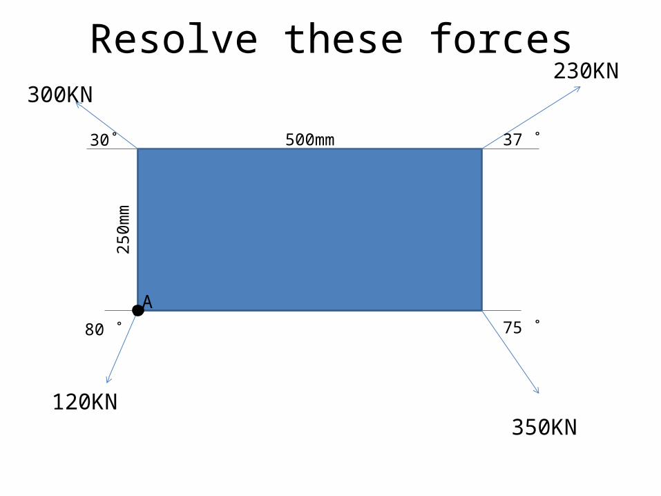
Resolve these forces
30˚ 37 ˚
80 ˚ 75 ˚
300KN230KN
350KN120KN
500mm25
0mm
A

Outcomes - Objectives
• Explain what tensile, compressive and shear forces are
• Explain direct and indirect stress and strain• Modulus of elasticity and how it is calculated.• What is a Factor of safety and it’s use.• Solve engineering problems relating to stress,
strain and modulus.
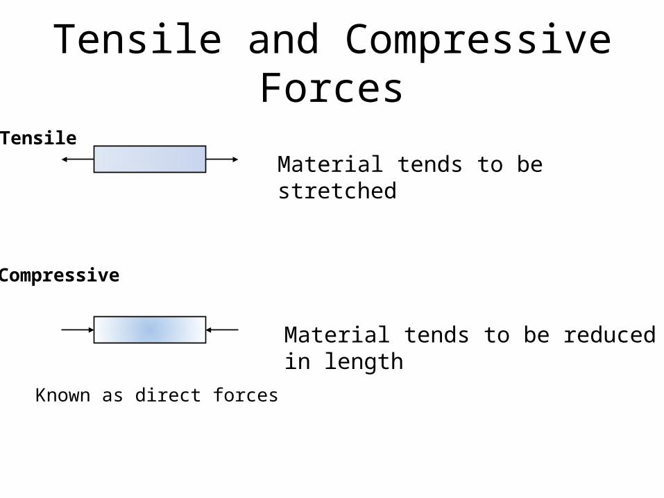
Tensile and Compressive Forces
TensileMaterial tends to be stretched
Compressive
Material tends to be reduced in length
Known as direct forces

Definitions for Direct ForcesStress (σ - Sigma) is the ratio of an applied force F to the area A over which it acts:
Strain (ε - Epsilon) is the relative change in the dimensions or shape of a body as the result of an applied stress:
kN/mm2, N/mm2,
𝑆𝑡𝑟𝑒𝑠𝑠 :𝜎=𝐹𝐴
𝑆𝑡𝑟𝑎𝑖𝑛 :𝜀= 𝛿𝑙𝑙
Ratio – no units; Dimensionless
L
DL
A
AF

L
dL
A
AF
First find area of wire:
𝜎=𝐹𝐴=
12004.909=244𝑁 /𝑚𝑚2
𝜀=𝛿 𝑙𝑙 =
0.32000=0.000150
Or - 150 x 10-6
Q1. A metal wire 2 m long and 2.5 mm in diameter is attached to the ceiling and a 1200 N weight is attached to the end the wire extends 0.3mm. Determine the Stress and the strain in the wire.
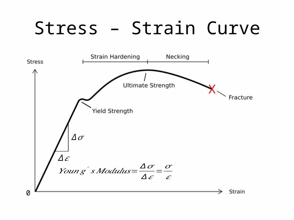
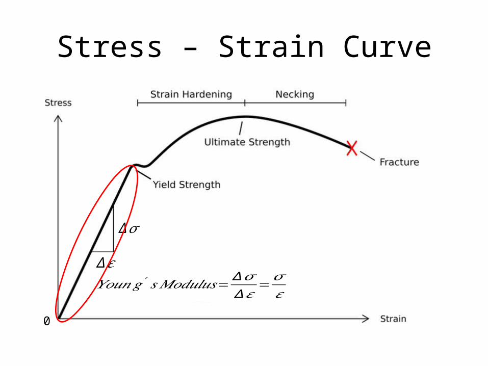
Stress – Strain Curve
𝑌𝑜𝑢𝑛𝑔′ 𝑠𝑀𝑜𝑑𝑢𝑙𝑢𝑠=∆ 𝜎∆𝜀 =𝜎𝜀
∆𝜎
∆ 𝜀
0
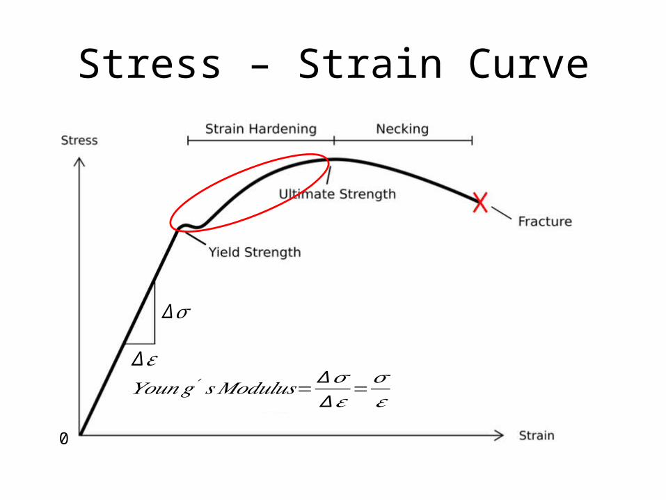
Stress – Strain Curve
𝑌𝑜𝑢𝑛𝑔′ 𝑠𝑀𝑜𝑑𝑢𝑙𝑢𝑠=∆ 𝜎∆𝜀 =𝜎𝜀
∆𝜎
∆ 𝜀
0

Young’s Modulus
𝑆𝑡𝑟𝑒𝑠𝑠 :𝜎=𝐹𝐴
𝑆𝑡𝑟𝑎𝑖𝑛 : 𝜀= 𝛿𝑙𝑙
= 𝑌𝑜𝑢𝑛𝑔′ 𝑠𝑀𝑜𝑑𝑢𝑙𝑢𝑠 :𝐸=𝜎𝜀
GN/m2
AKA: Modulus of elasticity, Tensile Modulus, Modulus
Remember:GN/m2 and kN/mm2 are the same size unit

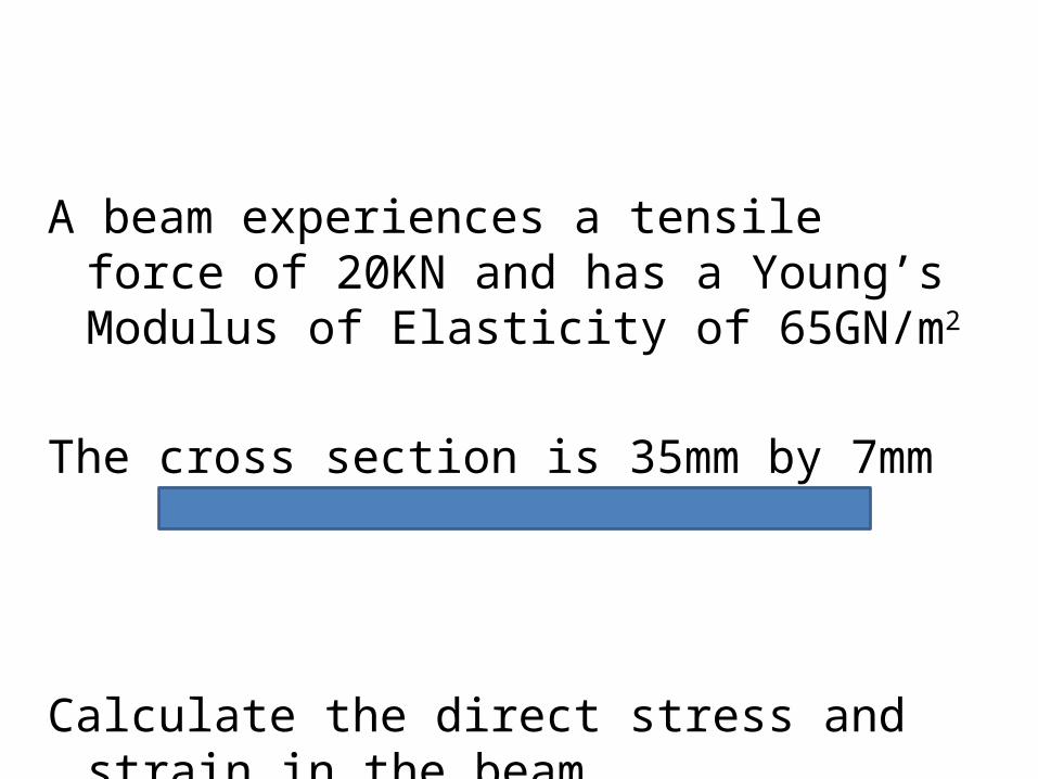
A beam experiences a tensile force of 20KN andhas a Young’s Modulus of Elasticity of 65GN/m2
The cross section is 35mm by 7mm
Calculate the direct stress and strain in the beam.

Stress – Strain Curve
𝑌𝑜𝑢𝑛𝑔′ 𝑠𝑀𝑜𝑑𝑢𝑙𝑢𝑠=∆ 𝜎∆𝜀 =𝜎𝜀
∆𝜎
∆ 𝜀
0

The Elastic LimitThe elastic limit is the maximum stress a body can experience without becoming permanently deformed.
WW
2 m
If the stress exceeds the elastic limit, the final length will be longer than the original 2 m – it begins to deform.
OkayBeyond limit
F
W
2 m
FStressA
Stress – Strain Curve
𝑌𝑜𝑢𝑛𝑔′ 𝑠𝑀𝑜𝑑𝑢𝑙𝑢𝑠=∆ 𝜎∆𝜀 =𝜎𝜀
∆𝜎
∆ 𝜀
0
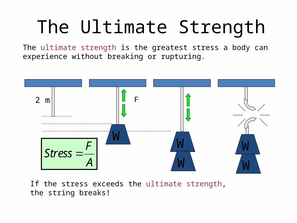
The Ultimate StrengthThe ultimate strength is the greatest stress a body can experience without breaking or rupturing.
If the stress exceeds the ultimate strength, the string breaks!
F
W WW
2 m
FStressA
WW

Stress – Strain Curve
𝑌𝑜𝑢𝑛𝑔′ 𝑠𝑀𝑜𝑑𝑢𝑙𝑢𝑠=∆ 𝜎∆𝜀 =𝜎𝜀
∆𝜎
∆ 𝜀
0
Ultimate Strength
A beam experiences a tensile force of 20KN and has a Young’s Modulus of Elasticity of 65GN/m2
The cross section is 35mm by 7mm
Calculate the direct stress and strain in the beam.


Tensile and Compressive Forces
TensileMaterial tends to be stretched
Compressive
Material tends to be reduced in length
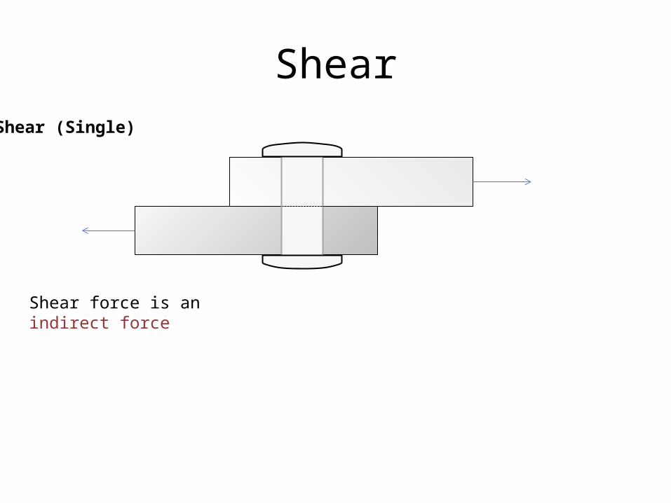
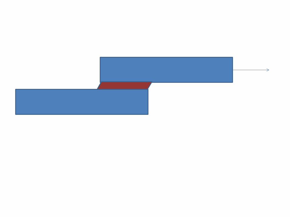
ShearShear (Single)
Shear force is an indirect force

Modulus of Ridgidity
h𝑆 𝑒𝑎𝑟 𝑆𝑡𝑟𝑒𝑠𝑠 :𝜏=𝐹𝐴
h𝑆 𝑒𝑎𝑟 𝑆𝑡𝑟𝑎𝑖𝑛 :γ= 𝑑𝑙
= h𝑆 𝑒𝑎𝑟 𝑀𝑜𝑑𝑢𝑙𝑢𝑠:𝐺=𝜏𝛾
GN/m2 AKA: Modulus of rigidity
Remember:GN/m2 and kN/mm2 are the same size unit

A
FFɣl
d
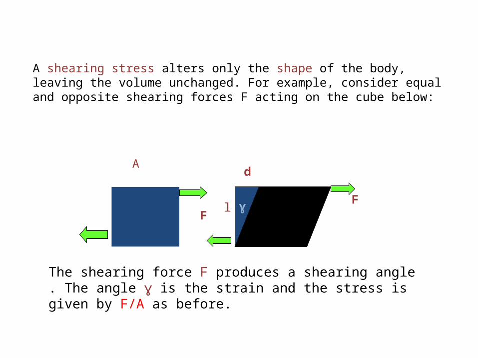
A shearing stress alters only the shape of the body, leaving the volume unchanged. For example, consider equal and opposite shearing forces F acting on the cube below:
The shearing force F produces a shearing angle . The angle ɣ is the strain and the stress is given by F/A as before.

ShearShear (Single)
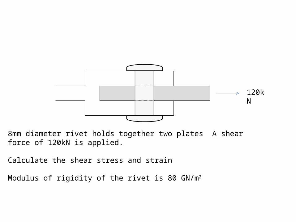
8mm diameter rivet holds together two plates A shear force of 120kN is applied.
Calculate the shear stress and strain
Modulus of rigidity of the rivet is 80 GN/m2
120 kN

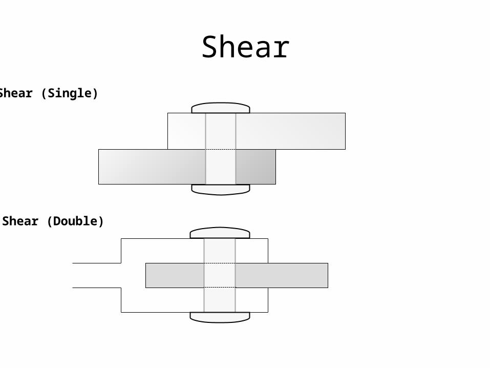
ShearShear (Single)
Shear (Double)
120kN
8mm diameter rivet holds together two plates A shear force of 120kN is applied.
Calculate the shear stress and strain
Modulus of rigidity of the rivet is 80 GN/m2

Angled Joints• Two beams are joined together at an angle of 45degrees by a
bolt of diameter of 20mm• A force of 120KN is applied in tension.
• Calculate the direct and shear stress in the bolt.
120kN
45o
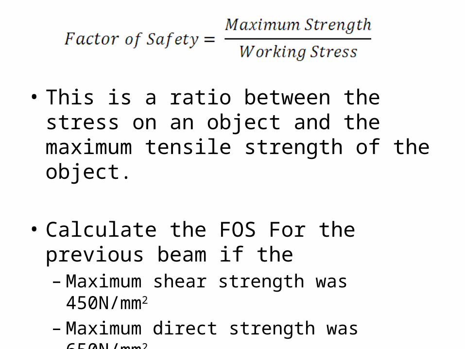
• This is a ratio between the stress on an object and the maximum tensile strength of the object.
• Calculate the FOS For the previous beam if the – Maximum shear strength was 450N/mm2 – Maximum direct strength was 650N/mm2
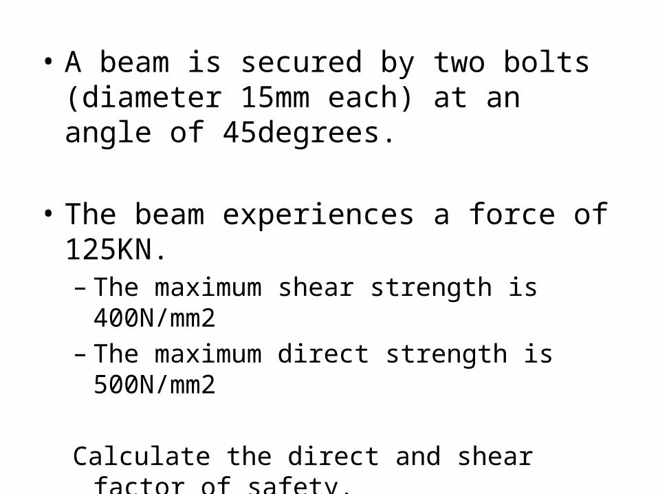
• A beam is secured by two bolts (diameter 15mm each) at an angle of 45degrees.
• The beam experiences a force of 125KN.– The maximum shear strength is 400N/mm2– The maximum direct strength is 500N/mm2
Calculate the direct and shear factor of safety.
Linear Expansion
Objective: Use the coefficient of linear expansion to calculate Force.

Coefficient of Linear Expansion
• This equation used in the first unit to find the expansion caused by an increase in temperature.
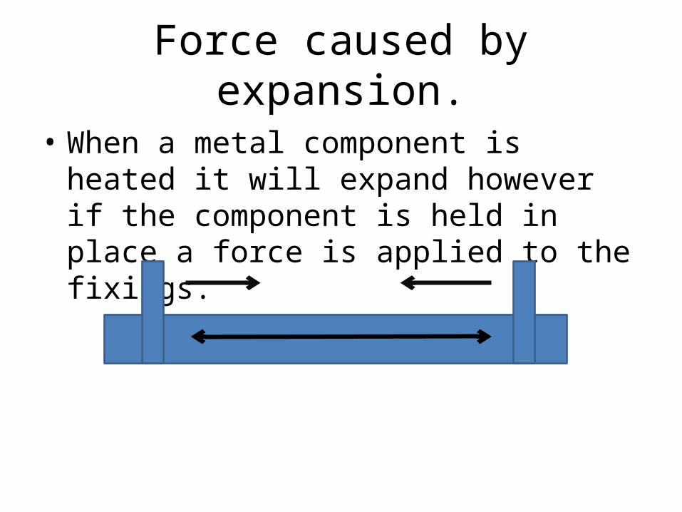
Force caused by expansion.
• When a metal component is heated it will expand however if the component is held in place a force is applied to the fixings.