stress state analysis on a rock anchor rc …163.com,2) [email protected],3) [email protected]...
TRANSCRIPT
Stress state analysis on a rock anchor RC foundation of wind driven
generator
*Shi Yan1), Bi-Cheng Song2), Wei Sun3), Han Yan4) and Qi-Le Yu5)
1), 2), 3), 5) School of Civil Engineering, Shenyang Jianzhu University, Shenyang Liaoning
110168, China 4) Liaoning Electric Power Survey & Design Institute, Shenyang Liaoning 110179, China
1) [email protected],2) [email protected],3) [email protected]
ABSTRACT
The stress state of a rock anchor reinforced concrete (RC) foundation of a wind driven generator located in the new constructed wind power station in Guodian Tieling Development Zone of China is numerically analyzed in this paper by using the large general-purpose finite element analysis (FEA) software ABAQUS, to discuss the mechanical characteristics of the rock anchor RC foundation, and validate the safety of normal use of the rock anchor foundation, and compare the developed rock anchor foundation with the traditional gravity one. The results show that the new-type RC foundation has greater advantage than the traditional one and it can completely replace the traditional gravity foundation in the condition of rock soil environment in the future.
1. INTRODUCTION
Wind energy is a kind of green energy resource which has potential development in the future. Wind energy is usually produced by a wind driven generator supported by a high tower. The tower is usually fixed on the huge reinforced concrete foundation to resist the wind induced horizontal shear force and overturning moment. To avoid happening of overturning, the RC foundation is usually designed to be huge and massive, resulting in the waste of concrete and reinforcement as well as the uneconomical occupation of land. ------------------------------------- 1) Professor 2)
Graduate Student
2202

Traditional RC foundations for wind driven generators are primarily divided into gravity foundations and pile ones. The above-mentioned two kinds of foundations have several shortcomings: (1) the forms of these foundations are too unitary to be adapted to different geological conditions; (2) independent expansion foundation has a good function of resisting vertical compressive force but weak capacity of resisting overturning moment because the separation for the concrete from soil at the foundation’s edge would play a controlling role; (3) for a high-power wind driven generator, the cantilevered length of the plate foundation is so great that the economy is poor and the form is unreasonable; (4) the volume of the excavation is great, especially for the foundation in rock soil environment, the excavation difficulty is great. Therefore, a new kind of RC foundation form needs to be developed.
The rock anchor RC foundation of the wind driven generator was developed and used at the first time in Guodian Tieling Development Zone of China. The proposed foundation can dramatically reduce the size of the foundation and improve the anti-overturning ability. However, the developed RC foundation is so new that the mechanical properties, especially the stress state, are less researched and reported. A three-dimensional model of the rock anchor RC foundation is established and numerically performed in this paper by using the large general purpose finite element analysis software ABAQUS. The force performance of the new-type rock anchor RC foundation of the wind driven generator is analyzed in this paper to focus on the stress state evaluation at the ultimate load conditions, considering the transfer mode of wind load and the nonlinear contact between the steel stub and the concrete foundation, and the bottom surface and the ground soil.
Domestic and foreign scholars researched and have a lot of fruits in the field. Fulton and Malcolm (Fulton and Malcolm 2007) researched the application of the support structure of foundation; Jonkman and Butterfield (Jonkman and Butterfield 2007) explored the theoretical and experimental about the single pile foundation, and proposed the basic design method about the single pile foundation; Reesel et al (Reesel et al 2008) described in detail the design method of RC foundations for wind driven generators, and used modern numerical methods to compare with traditional design methods; In China, Lu (Lu 1997) used the finite element method to deeply study the wind driven generator tower structure; Qin (Qin 2006) and Wu (Wu 2013) used the finite element method to simulate the foundation stress station, studied the foundation force mechanism, and used Ansys software to simulate the technical problems of the reinforced concrete structures; Gu (Gu 2009) used Ansys to preliminarily discuss about the load and the design of the wind driven generators; Zhang (Zhang 2001) and Wu (Wu 2011) discussed the mechanical characteristics of RC foundations for wind driven generators in the practical engineering. 2. PROJECT DESCRIPTION
2203
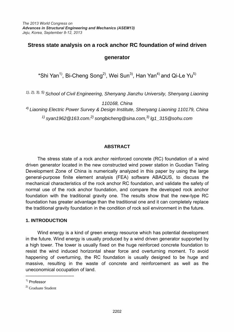
Guodian Tieling Development Zone is located in Tieling City of Liaoning Province in China where the wind energy resource is suitable for development. The number of 33 wind driven generators, which the power generating capacity of the newly installed generator is 1.5MW and the total capacity is 49.5MW that have installed in the newly constructed wind farm. One of the 33 generators is typically chosen as a computational object to take the numerical analysis. The chosen wind driven generator in this project is the UP82/1500 type IIIA that is made by Guodian United Power Technology Company, with the hub height of 65m and impeller diameter of 82.76m. Each of the generators is mainly located on the top of the low mountain hills, as shown in Fig. 1.
Fig. 1 The construction site of the RC foundation
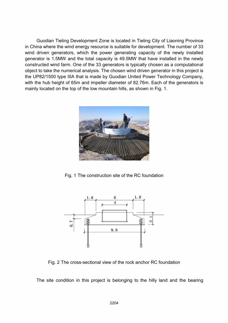
Fig. 2 The cross-sectional view of the rock anchor RC foundation The site condition in this project is belonging to the hilly land and the bearing
2204
stratum at the bottom of the wind driven RC foundation is moderately weathered granite.This foundation is mainly composed of the RC spread foundation and 28 steel anchorswith expanding head at the bottom end. The diameter of the foundation is 9.6m and the specification of the anchor bar is M60. The length of the anchor bar into the weathered granite is 4m and the length of the upper part of the steel bar anchored into the bearing RC platform is 800mm. The drilled holes during the construction for this expanding head anchor are filled by C30 cement mortar or C30 fine aggregate concrete, as shown in Fig.2.
3. PRINCIPLE OF FEA AND MODEL SETUP
3.1The principle of calculation According to China Design Code, the single anchor pile will conform to the
requirements of the following equation (2007)
0 0( )f e sT h D h (1)
In which, f is the coefficient of additional partial coefficients of foundation; is the design value of single anchor bar pulling force, kN; is the ultimate shear strength of rock, kPa; is the effective anchorage depth, for the straight anchor , and the bearing platform takes the length of the bottom bearing platform to the bottom of the anchor, m; is the bottom diameter of single anchor pile, m.
The multi-piles made up a group of anchor piles should comply with the requirements of the mentioned above Eq. (1) when pile spacing is more than 4 times the pile diameter in weathered rock or pile spacing is more than 6-8 times the pile diameter in the moderately weathered to strongly weathered rock or pile spacing is more than one third of the effective anchorage depth of anchor piles, when the pile spacing does not comply with the above conditions, besides comply with the requirements of the above formula but also comply with the requirements of the following Eq. (2).
0 0( )f e s fT h a h Q (2)
In which, is the circumscribed diameter of group anchor piles. For the anchor group with square arrangement,
ircumscribed diameter of group anchor piles. For the anchor group . For the anchor group pile with circular
arrangement, can take the diameter of the stub axis plus pile diameter, m.
3.2 Software DescriptionThe static performance of the developed foundation of the wind driven generator
of the newly constructed wind power station in Guodian Tieling Development Zone in China is numerically analyzed in this paper by using the large general-purpose finite
2205
element analysis software ABAQUS, to discuss the stress state of the rock anchor RC foundation. ABAQUS is the powerful FEA software with representative and increasingly widespread application of civil engineering structural analysis in China. During the foundation engineering design of the building structure, it has become the first choice of FEA software for ABAQUS has three following prominent features: (1) ABAQUS has a powerful nonlinear solution function and it applies Newton-Raphson algorithm for solving nonlinear problems; (2) ABAQUS provides a wealth of soil constitutive model, for example, (a) the concrete dispersion crack model, (b) the concrete brittleness cracking model, and (c) the concrete damage plasticity model; (3) The ABAQUS provides a well contact simulation. All of the mentioned superior performances make ABAQUS suitable for the numerical simulation of the rock anchor RC foundation of the wind driven generator.
3.3 Finite Element Model
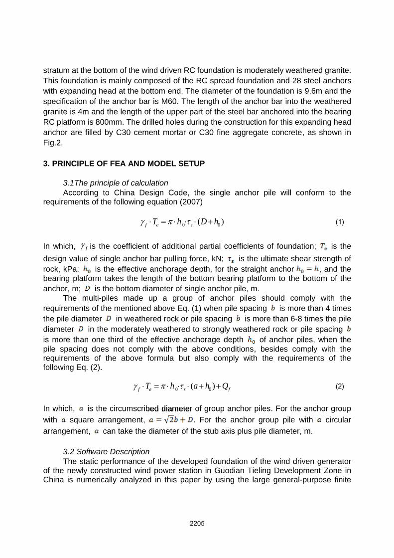
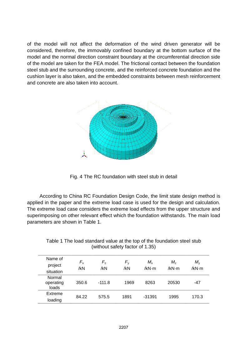
The FEA model for the rock anchor RC foundation of the wind driven generator is shown in Fig. 3, and the part of the RC foundation is shown in detail in Fig. 4. Considering the role of the ground in the calculation process, three times of the depth of the foundation diameter both in the depth direction and in the radial direction is taken to establish the FEA model.
Fig. 3 The FEA model of rock anchor RC foundation with soil The space Cartesian coordinate system is used for the calculation, and the top
center point of the foundation is taken as the origin of the coordinate. The constitutive relation of the material has a significant impact on the FEA results, and the concrete damage plasticity model, whose constitutive model is provided by ABAQUS, is selected according to the stress mechanism of the rock anchor RC foundation of the wind driven generator. According to Saint-Venant principle, the role, which the ground at the bottom
2206
of the model will not affect the deformation of the wind driven generator will be considered, therefore, the immovably confined boundary at the bottom surface of the model and the normal direction constraint boundary at the circumferential direction side of the model are taken for the FEA model. The frictional contact between the foundation steel stub and the surrounding concrete, and the reinforced concrete foundation and the cushion layer is also taken, and the embedded constraints between mesh reinforcement and concrete are also taken into account.
Fig. 4 The RC foundation with steel stub in detail
According to China RC Foundation Design Code, the limit state design method is applied in the paper and the extreme load case is used for the design and calculation.The extreme load case considers the extreme load effects from the upper structure and superimposing on other relevant effect which the foundation withstands. The main load parameters are shown in Table 1.
Table 1 The load standard value at the top of the foundation steel stub(without safety factor of 1.35)
Name of project
situation
Fx
/kNFz
/kNFy
/kNMx
/kN·mMz
/kN·mMy
/kN·m
Normal operating
loads350.6 -111.8 1969 8263 20530 -47
Extreme loading
84.22 575.5 1891 -31391 1995 170.3
2207
4. THE RESULT ANALYSIS
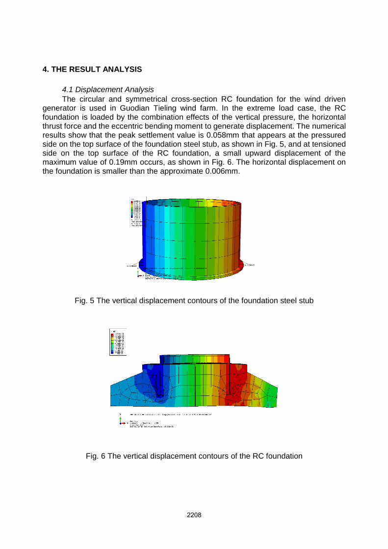
4.1 Displacement Analysis The circular and symmetrical cross-section RC foundation for the wind driven
generator is used in Guodian Tieling wind farm. In the extreme load case, the RC foundation is loaded by the combination effects of the vertical pressure, the horizontal thrust force and the eccentric bending moment to generate displacement. The numerical results show that the peak settlement value is 0.058mm that appears at the pressured side on the top surface of the foundation steel stub, as shown in Fig. 5, and at tensionedside on the top surface of the RC foundation, a small upward displacement of the maximum value of 0.19mm occurs, as shown in Fig. 6. The horizontal displacement on the foundation is smaller than the approximate 0.006mm.
Fig. 5 The vertical displacement contours of the foundation steel stub
Fig. 6 The vertical displacement contours of the RC foundation
2208

4.2 Stress Distribution Analysis In order to reflect the yield damage of the RC foundation, the calculated stress
results are given by the Von Mises yield criterion
(3)
In which, 、 are the principal stresses in the Eq. (3), respectively.
Fig. 7 The stress nephogram of the foundation and the bottom surface of the rock
The stress nephogram of the foundation and the bottom surface of the rock mass are shown in Fig. 7. It can be seen from the Figure that the largest stress for the foundation concrete occurs at the bottom of the foundation stub with the maximum stress value of 505.7kPa, which is less than the bearing capacity of foundation 1.2fa of 720kPa (the foundation bearing capacity is 600kPa).The maximum compressive stress of the foundation steel stub is 110MPa, which occurs at the top of the foundation stub in the compression zone. The maximum tensile stress of 74.57MPa occurs on top of the foundation steel stub in the tension zone, as shown in Fig. 8. The emergence of tension and compression stress generates due to the stress concentration caused by the bending moment, and they are all less than the ultimate bearing capacity of the foundation stub which means the RC foundation is safe in the ultimate limit state. Themaximum compressive stress of the reinforcement, which occurs in the vicinity at the compression side of the foundation stub, is 7.067MPa. Tensile stress is generated in the tension zone range of the RC foundation and the value is 194kPa, which means the rock anchors play a role.
2209
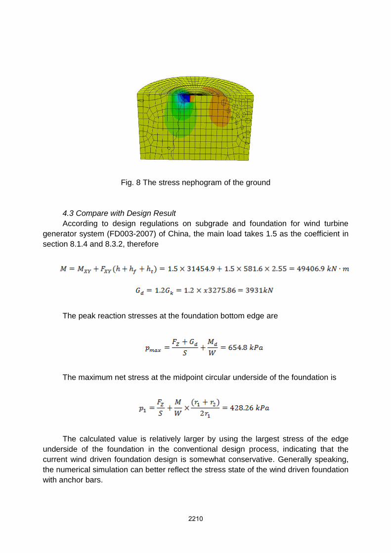
Fig. 8 The stress nephogram of the ground
4.3 Compare with Design Result According to design regulations on subgrade and foundation for wind turbine
generator system (FD003-2007) of China, the main load takes 1.5 as the coefficient in section 8.1.4 and 8.3.2, therefore
The peak reaction stresses at the foundation bottom edge are
The maximum net stress at the midpoint circular underside of the foundation is
The calculated value is relatively larger by using the largest stress of the edge underside of the foundation in the conventional design process, indicating that the current wind driven foundation design is somewhat conservative. Generally speaking, the numerical simulation can better reflect the stress state of the wind driven foundation with anchor bars.
2210

5. DISPLACEMENT COMPARE WITH NON-ANCHOR FOUNDATION
To compare the stress state of the developed foundation with that without rock anchor bars, a new wind driven RC foundation model is rebuilt by using ABAQUS. The dimension and material properties are the same with the above developed one, and the same load (ultimate load) is applied on the two kinds of foundations, to compare the results of the stress and displacement and observe the difference between two kinds of foundations and the superiority of the anchor foundation. The stress-strain curve for the underside of the foundation along the diameter direction is shown in Fig. 9, and the displacement curve via diameter for the underside of the foundation is shown in Fig. 10.
Fig. 9 Comparison of stress-strain curves at the underside of foundations From the Fig. 9 and Fig. 10, we can see that the displacement for the non-anchor
wind driven foundation has been far greater than that of the rock anchor wind driven foundation under the same load. The foundation would have been overturning in such a large displacement if the dimension of the foundation is not great enough or the foundation has no the rock anchor bars. According to the stress-diameter curve, we can also see the underside of the non-anchor foundation’s stress is essentially zero, which means that the foundation might indeed have been departing from the ground. Through the comparison, we can see the rock anchor foundation’s superiority to resist overturning is obvious. To achieve the same bearing capacity, the non-anchor foundation needs more concrete than rock anchor foundation, and this means the rock anchor foundation can save concrete.
2211
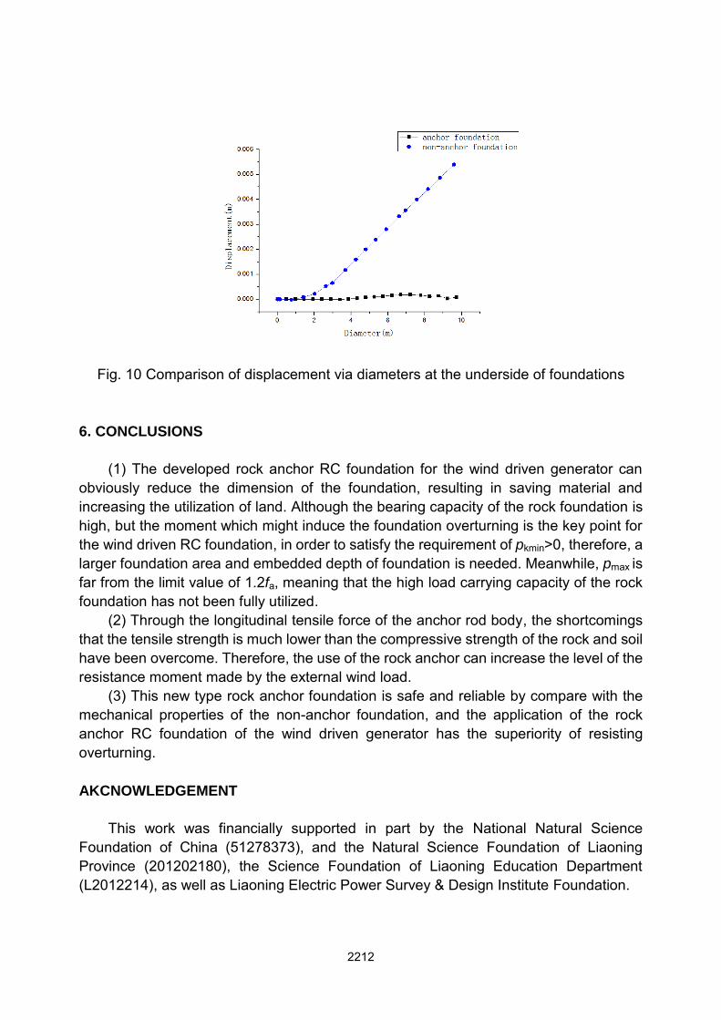
Fig. 10 Comparison of displacement via diameters at the underside of foundations
6. CONCLUSIONS
(1) The developed rock anchor RC foundation for the wind driven generator can obviously reduce the dimension of the foundation, resulting in saving material and increasing the utilization of land. Although the bearing capacity of the rock foundation is high, but the moment which might induce the foundation overturning is the key point for the wind driven RC foundation, in order to satisfy the requirement of pkmin>0, therefore, a larger foundation area and embedded depth of foundation is needed. Meanwhile, pmax is far from the limit value of 1.2fa, meaning that the high load carrying capacity of the rock foundation has not been fully utilized.
(2) Through the longitudinal tensile force of the anchor rod body, the shortcomings that the tensile strength is much lower than the compressive strength of the rock and soil have been overcome. Therefore, the use of the rock anchor can increase the level of the resistance moment made by the external wind load.
(3) This new type rock anchor foundation is safe and reliable by compare with the mechanical properties of the non-anchor foundation, and the application of the rock anchor RC foundation of the wind driven generator has the superiority of resisting overturning. AKCNOWLEDGEMENT
This work was financially supported in part by the National Natural Science
Foundation of China (51278373), and the Natural Science Foundation of Liaoning Province (201202180), the Science Foundation of Liaoning Education Department (L2012214), as well as Liaoning Electric Power Survey & Design Institute Foundation.
2212
REFERENCES
Fulton, G.R. and Malcolm, D.J. (2007), “Semi-submersible platform and anchor foundation systems for wind turbine support: August 30, 2004 –May 31, 2005”, Proceedings of Concept Marine Associates Inc. Long Beach, California.
Gu, F.B. and Cui, X.W. (2009), “Discussion on the concrete structure forms of wind turbine tower,” Journal of Xinjiang Agricultural University, 3(32), 82-85. (In Chinese)
Jonkman, J. and Butterfield, S. (2007), “Offshore code comparison collaboration within IEA wind annex XXIII: phase II results regarding monopile foundation modeling”, Proceedings of IEA European Offshore Wind Conference, Berlin.
Lou, W.J. and Sun, B.N. (2000), “Wind-structure-coupling effects and buffeting responses,” Engineering Mechanics, 10(5), 21-22. (In Chinese)
Lu, P., Xue, S.T. (1997), “The finite element analysis on static and dynamic characteristic of the conical tube tower structure for the wind turbine,” ACTA Energiae Solaris Sinica, 18(4), 359-364.
Qin, J. (2006), “Finite element analysis for bearing of the concrete rigidity foundation,” Sichuan Architecture, 26(4), 63-65. (In Chinese)
Reesel, L.C. and Wang, S.T. (2008), “Design of foundations for a wind turbine employing modern principles”, Proceedings of Research to Practice in Geotechnical
Engineering Congress 2008, New Orleans. Technical Standard for Wind Power Station (FD 003-2007). (2007), “Design regulations
on subgrade and foundation for wind turbine generator system,” Hydropower and Water Resources Planning and Engineering Institute. (In Chinese)
Wu, K. and Ma, M.Y. (2013), “Mechanism model test of interaction between bucket foundation and soil subjected to torsional resistance,” Journal of Jiangsu University, 34(1), 86-90. (In Chinese)
Wu, S. and Yang, H. (2011), “The three-dimensional finite element analysis of the foundation for wind turbo-generator units of Liziqing wind farm,” Yunnan Water Power,
27(2), 1-3. (In Chinese) Xue, S.T. and Li, A.Y. (2008), “Dynamic response analysis of a high rise building
subjected to across-wind load considering soil-structure interaction,” Journal of Vibration and Shock, 27(10), 152-155. (In Chinese)
Zhang, D. (2001), “Finite element analysis on Huitengxile wind-driven generator foundation,” Journal of Yellow River Conservancy Technical Institute, 23(1), 30-33. (In Chinese)
2213