stress intensification & flexibility in pipe stress · pdf filecreates a high...
TRANSCRIPT
International Journal of Modern Engineering Research (IJMER)
www.ijmer.com Vol. 4, Issue. 3, May-June. 2013 pp-3390-3397 ISSN: 2249-6645
www.ijmer.com 1 | Page
Gaurav Bhende
1, Girish Tembhare
2
1(Departmen of Mechanical Engineering,VJTI,Mumbai,India
Email: [email protected])
2 (Department of Mechanical Engineering, VJTI, Mumbai, India
Email: [email protected])
ABSTRACT : A typical piping system consists of combination of pipes and various fitting components like bends, Tees,
O’lets etc. The plant piping systems are subjected to various types of loading due to Weight, Pressure, Temperature, wind,
water hammer etc. causing possible failure modes, based on type of loading, as plastic, rupture, fatigue, creep etc. In
addition, pipe exhibits different geometric characteristics at fittings which have notable effect on the flexibility of the piping
system. This in turn has influence on stress concentration at fittings and the loads produced due to it. This paper attempts to
explain basic concepts of flexibility, stress intensification factors and their equations provided in ASME B31 codes. Authors
have few observations on B31 SIF equations and hence attempted to compare the results of B31 SIF results against Finite
Element Analysis providing the results at the end.
Keywords: Flexibility characteristics, Flexibility factor, Stress intensification factor.
I. INTRODUCTION
In a typical piping system two pipes can be connected to each other directly as pipe to pipe joint or by means of various
fittings viz. bends, Tee’s, O’lets etc. Simple beam theories which can be applied to straight pipe may not be able to reflect
true behavior of the piping fittings due to varying cross sections, thickness, curvatures etc. Hence it is essential to consider
additional stresses at the fittings by introducing Stress Intensification Factor (SIF). This paper manly discusses about the
stress intensity calculations followed in Process Piping Plants referring to code ASME B31.3 [1] based on Markl’s [2] great
work in this domain.
II. FLEXIBILITY CHARACTERISTICS, FLEXIBILITY FACTOR & STRESS INTENSIFICATION FACTOR
To elaborate the concept of Stress Intensification factor (SIF), an example of bend has been considered.
Abbreviations: h =Flexibility characteristics
T =Nominal wall thickness of header pipe or bend, in
R1 =Bend radius, in
r2 =Mean radius of matching pipe, in
Sb =Bending stress, PSI
M =Bending moment, lb-in
Z =Section modulus of pipe, in3
i =Stress intensification factor
N =Number of load cycles
2.1 Flexibility Characteristics, h
It is a geometric characteristics based on the nominal wall thickness and mean radius of the fitting. ASME B31.3 defines
it as a unit less number calculated based on type of fitting.
Example: for a bend
h = T R1 / r22
(1)
Flexibility characteristics is used to calculate Flexibility factor and SIF. It is in inverse proportion to Flexibility factor
and SIFs.
2.2 Flexibility factor, k [3]
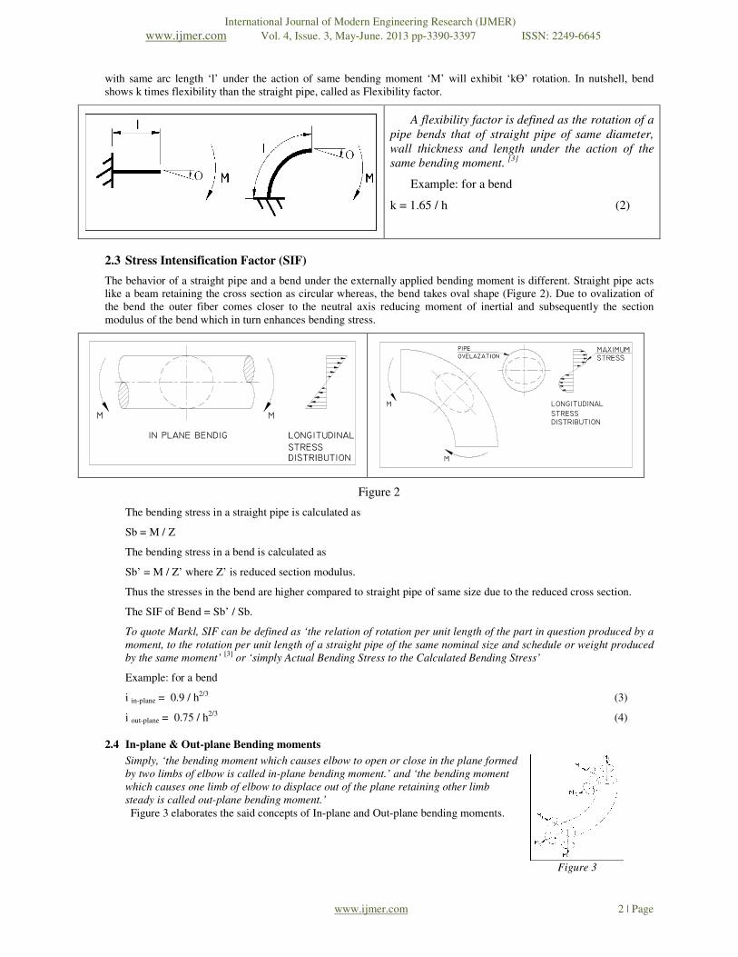
The most common fitting used in Piping system is ‘Bend’ due to its inherent flexibility characteristic which results due
to its ability to ovalize under the action of bending moment. Consider a straight pipe (refer Figure 1) with length ‘l’
which will produce rotation ‘Ө’ under the action of bending moment ‘M’. A bend having same diameter and thickness
Stress Intensification & Flexibility in Pipe Stress
Analysis
International Journal of Modern Engineering Research (IJMER)
www.ijmer.com Vol. 4, Issue. 3, May-June. 2013 pp-3390-3397 ISSN: 2249-6645
www.ijmer.com 2 | Page
with same arc length ‘l’ under the action of same bending moment ‘M’ will exhibit ‘kӨ’ rotation. In nutshell, bend
shows k times flexibility than the straight pipe, called as Flexibility factor.
A flexibility factor is defined as the rotation of a
pipe bends that of straight pipe of same diameter,
wall thickness and length under the action of the
same bending moment. [3]
Example: for a bend
k = 1.65 / h (2)
2.3 Stress Intensification Factor (SIF)
The behavior of a straight pipe and a bend under the externally applied bending moment is different. Straight pipe acts
like a beam retaining the cross section as circular whereas, the bend takes oval shape (Figure 2). Due to ovalization of
the bend the outer fiber comes closer to the neutral axis reducing moment of inertial and subsequently the section
modulus of the bend which in turn enhances bending stress.
LONGITUDINAL
STRESS
DISTRIBUTION
Figure 2
The bending stress in a straight pipe is calculated as
Sb = M / Z
The bending stress in a bend is calculated as
Sb’ = M / Z’ where Z’ is reduced section modulus.
Thus the stresses in the bend are higher compared to straight pipe of same size due to the reduced cross section.
The SIF of Bend = Sb’ / Sb.
To quote Markl, SIF can be defined as ‘the relation of rotation per unit length of the part in question produced by a
moment, to the rotation per unit length of a straight pipe of the same nominal size and schedule or weight produced
by the same moment’ [3]
or ‘simply Actual Bending Stress to the Calculated Bending Stress’
Example: for a bend
i in-plane = 0.9 / h2/3 (3)
i out-plane = 0.75 / h2/3
(4)
2.4 In-plane & Out-plane Bending moments
Simply, ‘the bending moment which causes elbow to open or close in the plane formed
by two limbs of elbow is called in-plane bending moment.’ and ‘the bending moment
which causes one limb of elbow to displace out of the plane retaining other limb
steady is called out-plane bending moment.’
Figure 3 elaborates the said concepts of In-plane and Out-plane bending moments.
Figure 3
International Journal of Modern Engineering Research (IJMER)
www.ijmer.com Vol. 4, Issue. 3, May-June. 2013 pp-3390-3397 ISSN: 2249-6645
www.ijmer.com 3 | Page
III. EXPERIMENTAL EVALUATION & THEOROTICAL CALCULATIONS OF SIF [4]
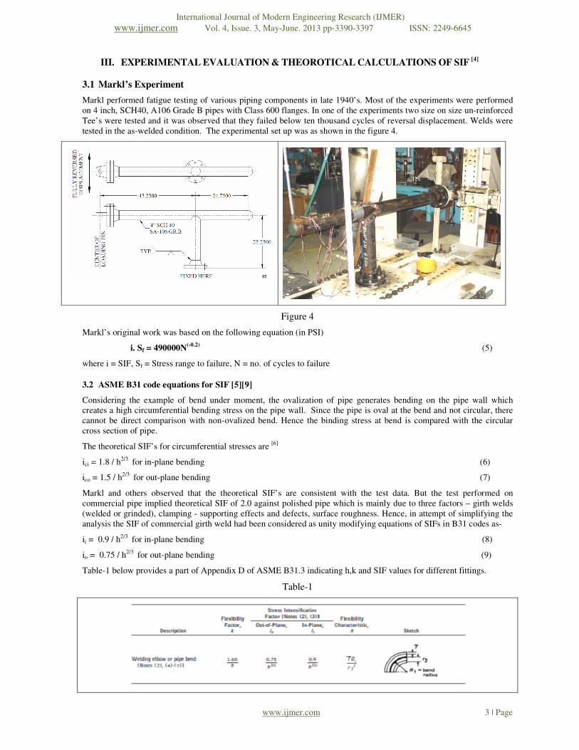
3.1 Markl’s Experiment
Markl performed fatigue testing of various piping components in late 1940’s. Most of the experiments were performed
on 4 inch, SCH40, A106 Grade B pipes with Class 600 flanges. In one of the experiments two size on size un-reinforced
Tee’s were tested and it was observed that they failed below ten thousand cycles of reversal displacement. Welds were
tested in the as-welded condition. The experimental set up was as shown in the figure 4.
Figure 4
Markl’s original work was based on the following equation (in PSI)
i. Sf = 490000N(-0.2)
(5)
where i = SIF, Sf = Stress range to failure, N = no. of cycles to failure
3.2 ASME B31 code equations for SIF [5][9]
Considering the example of bend under moment, the ovalization of pipe generates bending on the pipe wall which
creates a high circumferential bending stress on the pipe wall. Since the pipe is oval at the bend and not circular, there
cannot be direct comparison with non-ovalized bend. Hence the binding stress at bend is compared with the circular
cross section of pipe.
The theoretical SIF’s for circumferential stresses are [6]
ici = 1.8 / h2/3
for in-plane bending (6)
ico = 1.5 / h2/3 for out-plane bending (7)
Markl and others observed that the theoretical SIF’s are consistent with the test data. But the test performed on
commercial pipe implied theoretical SIF of 2.0 against polished pipe which is mainly due to three factors – girth welds
(welded or grinded), clamping - supporting effects and defects, surface roughness. Hence, in attempt of simplifying the
analysis the SIF of commercial girth weld had been considered as unity modifying equations of SIFs in B31 codes as-
ii = 0.9 / h2/3 for in-plane bending (8)
io = 0.75 / h2/3
for out-plane bending (9)
Table-1 below provides a part of Appendix D of ASME B31.3 indicating h,k and SIF values for different fittings.
Table-1

International Journal of Modern Engineering Research (IJMER)
www.ijmer.com Vol. 4, Issue. 3, May-June. 2013 pp-3390-3397 ISSN: 2249-6645
www.ijmer.com 4 | Page
3.3 SIF calculation example
Based on different types of fittings ASME B31 code provides empirical formulae to calculate h, k and SIFs. Consider an
Unreinforced fabricated Tee junction having following data-
Header outside diameter: Dh = 12.75”
Header nominal thickness: T = 0.375”
Branch outside diameter: Db = 10.625”
Branch nominal thickness: t = 0.365”
Mean radius of header: r2 = 6.1875” Figure 5
Flexibility characteristics: h = T / r2 = 0.375 / 6.1875 = 0.06
Flexibility factor: k = 1 (as per ASME B31, Appendix D)
Out-plane SIF: io = 0.9 / h2/3
= 0.9 / 0.062/3
= 0.9 / 0.154 = 5.83 (10)
In-plane SIF: ii = 0.75* io+1/4 = 0.75 * 5.83 + 0.25
= 4.62 (11)
The above results have compared with CAESAR II® [7]
output and found consistent.
IV. VALIDATING B31 SIF EQUATIONS AGAINST FEA ANALYSIS
Besides other observations on B31 SIF equation, authors have
concentrated on one important observation that the SIF value of any
fitting or elbow is irrespective of the branch properties i.e. branch
diameter and branch thickness. Authors selected the unreinforced
fabricated tee junction, similar to one of the Markl’s experiment as
shown in Figure 4 to find out effect of various header and branch
properties on SIF. Number of FEA models were analyzed changing
one variable at a time out of four variables affecting SIF viz. Header
outside diameter, header thickness, branch outside diameter and
branch thickness
Table-2: Experiment summary
Factors EXP-1 EXP-2 EXP-3 EXP-4
Header diameter C C C V
Header thickness C C V C
Branch diameter C V C C
Branch thickness V C C C
V = varying parameter, C = parameter kept constant

International Journal of Modern Engineering Research (IJMER)
www.ijmer.com Vol. 4, Issue. 3, May-June. 2013 pp-3390-3397 ISSN: 2249-6645
www.ijmer.com 5 | Page
4.1 FEA Model
ANSYS[8]
software used to simulate experiment set up shown in Fig. 6. To achieve the surface geometry at the junction,
a 2D element ‘shell 63’ with real constant as pipe thickness has been used. The boundary conditions are as shown in Figure
4. A force applied at flange end and the stresses were checked at the Unreinforced Tee junction. These stresses were
compared against pipe with circular cross section to get SIF.
Figure 6
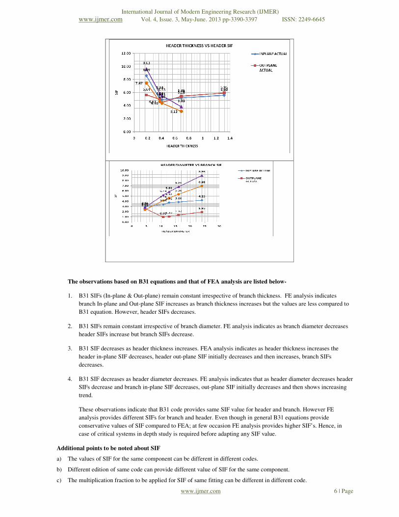
4.2 Results based on ASME B31 equations
The results based on B31 equations were obtained using CAESAR II analysis and that based on FEA analysis were
obtained using ANSYS. Both the results have been graphically plotted in Fig.7 below.
International Journal of Modern Engineering Research (IJMER)
www.ijmer.com Vol. 4, Issue. 3, May-June. 2013 pp-3390-3397 ISSN: 2249-6645
www.ijmer.com 6 | Page
The observations based on B31 equations and that of FEA analysis are listed below-
1. B31 SIFs (In-plane & Out-plane) remain constant irrespective of branch thickness. FE analysis indicates
branch In-plane and Out-plane SIF increases as branch thickness increases but the values are less compared to
B31 equation. However, header SIFs decreases.
2. B31 SIFs remain constant irrespective of branch diameter. FE analysis indicates as branch diameter decreases
header SIFs increase but branch SIFs decrease.
3. B31 SIF decreases as header thickness increases. FEA analysis indicates as header thickness increases the
header in-plane SIF decreases, header out-plane SIF initially decreases and then increases, branch SIFs
decreases.
4. B31 SIF decreases as header diameter decreases. FE analysis indicates that as header diameter decreases header
SIFs decrease and branch in-plane SIF decreases, out-plane SIF initially decreases and then shows increasing
trend.
These observations indicate that B31 code provides same SIF value for header and branch. However FE
analysis provides different SIFs for branch and header. Even though in general B31 equations provide
conservative values of SIF compared to FEA; at few occasion FE analysis provides higher SIF’s. Hence, in
case of critical systems in depth study is required before adapting any SIF value.
Additional points to be noted about SIF
a) The values of SIF for the same component can be different in different codes.
b) Different edition of same code can provide different value of SIF for the same component.
c) The multiplication fraction to be applied for SIF of same fitting can be different in different code.
International Journal of Modern Engineering Research (IJMER)
www.ijmer.com Vol. 4, Issue. 3, May-June. 2013 pp-3390-3397 ISSN: 2249-6645
www.ijmer.com 7 | Page
REFERENCES
[1] American Society of Mechanical Engineers, ASME B31.3 code for Pressure Piping. Edition 2010.
[2] Markl A.R.C. and George, H.H., 1950,”Fatigue Tests on Flanged assemblies,” transactions of the ASME, 72(1), pp. 77-
87.
[3] Diehl, David., “The Bend Flexibility Factor”, COADE Mechanical Engineering News, October 2002.
[4] Hinnant, Chris., Paulin, Tony.,Paulin Research Group, “Experimental Evaluation of the Markl Fatigue Methods and
ASME Piping Stress Intensification Factors”, 2008 ASME PVP Conference, Chicago, IL, July 28, 2008
[5] Peng, L.C., Peng, T., Peng Engineering, Houston, Texas, USA, “Pipe Stress Engineering”, ASME.
[6] M.W. Kellogs Company, 1956, “Design of Piping Systems, revised 2nd
ed., John Wiley & Sons, New York.
[7] Intergraph CAESAR II® is a comprehensive and standard program for Pipe Stress Analysis used worldwide .
[8] ANSYS version 14, world recognized FEA based software.
[9] Bhattacharya, Anindya., Long, Daniel., “A Finite Element based Investigation of Stress Intensification and Flexibility
Factors for Pipe Bends within and outside the Limitations of ASME B31 Piping Codes.”
Acknowledgement: Authors acknowledge the contribution of Shekhar Shivaji Maragudri and Jay Rajendra Tank
towards FEA modeling.