stress analysis ’ of concrete pipe · pdf fileunited states department of the interior...
TRANSCRIPT

ENGINEERING MONOGRAPHS No. 6
United States Department of the Interror BUREAU OF RECLAMATION
STRESS ANALYSIS ’ of CONCRETE PIPE
by H. C. OLANDER
Denver, C@orado
October 1950

United States Department of the Interior
Bureau of Reclamation
Engineering Monographs
No. 6
STRESS ANALYSIS of CONCRETE PIPE
by H. C. Olander, Engineer Canals Division
Branch of Design and Construction
Denver Federal Center Denver, Colorado

ENGINEERING MONOGRAPHS are published in limited editions for the technical staff of the Bureau of Reclamation and interested technical circles in government and private agencies. Their purpose is to record developments, inno- vations, and progress in the engineering and scientific techniques and practices that are em- ployed in the planning, design, construction, and operation of Reclamation structures and equip- ment. Copies may be obtained from the Bureau of Reclamation, Denver Federal Center, Denver, Colorado, and Washington, D. C.

INTRODk’ION
Stress analysis of concrete pipe is in part based on the assumed distribution of earth pressures. Most commonly it has been assumed that the vertical earth load is uniformly distributed over the horizon- tal width of the pipe and that the lateral load is exerted so that the force diagram is trapezoidal in shape, applied on both sides, and extending the full height of the pipe. Further, it has been assumed that the reaction due to these loads is uniform- ly distributed over the full width of that portion of the bottom of the pipe in con- tact with the supporting &ace. That these assumptions are rather arbitrary has long been recognized and efforts have been made to develop assumptions that would agree more closely with tests and with the gen- eral fund of knowledge about soil mechanics.
In 1930, the late Dr. Anson Marston, director of the Iowa Engineering Experi- ment Station at Iowa State College, advanced the theory that earth pressures on a rigid conduit and the reactions to those pressures would be exerted in such a manner that the force diagram representing the pressures would have characteristic bulb-like shapes above and below the outline of the pipe. Dr. Marston’s theory was confirmed and ex- tended by an investigation carried out at the Iowa Engineering Experiment Station and reported by IvL G. Spangler of the Sta- tion staff.
While the design of the concrete pipe for the first section of the Salt Lake Aque- duct was being developed in 1938, W. A. Larsen and H. W. Birkeland, Bureau of Rec- lamation engineers under the direction of C. P. Vetter, who was in charge of the de- sign, developed an analysis based on the assumption of bulb-like distribution of earth loads and soil reactions. This assumption closely approximates actual conditions as disclosed by tests. Since 1938, a number of other pipe lines have been designed, and the original analysis has been expanded so that various widths of bedding of the pipe may be analyzed.
In the original analysis the least work method by summation was used, but in sub- sequent studies a mathematical solution using integral equations was developed and is described in this monograph
STRESS ANALYSIS OF CONCRETE PIPE
General Under ordinary conditions a pipe placed
under a fill is subjected to loads due to earth
pressure around the pipe, the dead load of the pipe itself, and the internal hydrostatic pressure. For convenience of design the hydrostatic pressure is divided into two parts: (a) that part producing a uniform internal pressure, of which the head H is measured from the hydraulic gradient to the top of the inside of the pipe; and (b) the remaining part of the pressure of which the head is measured from the top to the bottom of the inside of the pipe.
The uniform internal pressure, part (a), produces only uniform tension around the pipe and is equal to 62.4 Hro, where r. is the inside radius of the pipe in feet, and H is the head in feet measured as stated above.
The remaining part of the hydrostatic pressure produces bending, direct, and shear stresses in the pipe. This part is designated as water load and will be dis- cussed in combination with earth load and dead load,
Earth Load, Dead Load, and Water Load
The assumptions for the distribution of earth pressures are based on results obtained from tests as summarized in Bul- letin 112 of the Iowa Engineering Experi- ment Station. Figure 1 is developed from data in this bulletin and shows the distri- bution of earth pressures around a rigid pipe placed on compacted bacuill, repre- senting the ordinary condition of a pipe placed under fill or in a wide trench The
FIGURE 1 - Earth pceeuree arod a rigid pipe plac& o? cwcted back- fill exhibit characterietlc bulb-ehaped patterm of dietributlan.

.
reaction resisting external loads is as- sumed to be distributed over the bottom of the pipe, limited by a definite central angle and varying as gome function of the angle 9, see Figure 4. The limits of the central angle will depend on the beddin of the pipe, see Figure 2. Generally a 90 8 angle is used, but the analysis of the pipe has been prepared here for central angles
FxGmE2d3zeeeeaalyi3leofrigia~pe requiree that these basic dlmeneiox~~~ be m.
of 450, 900, 1200, and 180°. In the anal- ysis, loads snd pressure distribution around the pipe are assumed to be symmetrical about the vertical centerline.
Nomenclature
pt=unit external pressure from earth. It is a function of angle 9 and the total downward force is equal to the weight of earth on the pipe.
Pb = unit external pressure on the bot- tom of the pipe. It is a func- tion of angle 9 and equals the reaction of the earth on the pipe, from earth load, water load, and dead load.
Pi = unit internal water pressure from part (b) of hydrostatic pres- sure mentioned previously.
= 62.4ro(l-cos 9)
h = height of earth fill above pipe in feet. See Figure 2.
r = radiusi;ffzee;terline of pipe shell
ro = radius of inside of pipe in feet.
we = unit weight of effective earth cov- er in pounds per cubic foot.
A = total y;i$t,o; earth on pipe e
W = total weight of water in pip2 per foot of pipe = 62.4n r. .
t = thickness of pipe shell in feet.
D = total Le;i&t $pipe = 2nr15Ot n
IvI& P& VA = moment, thrust, and shear respectively on sec- tion at angle 9 when pipe is assumed to be cut at top. See Figure 3b.
-9 PO9 v* = final moment, thrust, and shear on section at angle 9.
Pipe Analysis
The stress analysis is made by the least work method, taking advantage of certain known facts about the final deflected shape of the pipe ring, resulting from the sym- metrical loads assumed. Due to the as- sumed loads the pipe must deflect sym- metrically about the vertical centerline, snd the two points on this centerline, top and bottom, will neither rotate nor deflect hori- zontall . cut in K
The pipe then is assumed to be alf and each half considered as a
curved cantilever beam free at the top and fixed at the bottom. With the pipe cut in this manner, earth, water, and dead loads will cause the top to deflect. Thrust Ho and Moment MO, see Figure 3, are then calculated to restore the free end to its final position so that its horizontal deflec- tion and rotation are zero. Shear V. at the top is zero.
a. b.
FIGURE 3 - Moment, ehear, and thrut are determined seeuutlng that the pipe lecutatthetiYpdlsfreeto&flect. At a, the forcee are seeumed on the vertical centerline; and at b, at any angle 0 to that centerldne.

in detail, for earth load, water load, and dead load The solutions for other assumed bearing areas are similar and only those equations which are different will be given as they appear.
FIGmE 4 -with a central augle of n/2, earth preeeuree and reactlone eiblblt the characterietlc bulb sbapee.
1. Analysis for Reaction over Central Angle n/z.
A Earth Load. See Figure 4.
assume Pt to vary as cos P,co$e
$3, or Pt =
3 then 2jozn Pocod9cos9rd9 = A
from which PO = A 1.697r
assume pb to vary as cos29, or Pb = P,cos28
/
n then 2 3 P,,cos29co&rd6 = A
-n 4
p =L, A =-cos20 n .943r ‘b .943r
(1)
(2)
The forces on the cut section at 9, are as follows:
From Pt, where 0 P 9s 9 II
M; = l.OBlAr(cos~9 - CO?&)
P:, = LO~~A(COS~I - c0se)
VA = l.O61A(sin9 - tsin$3)
3 Where zn Z 9Sn
Mt, = 0.75OAr(O. 667 sin 9
- 0.748 COS e)
Pi =+e- i.i22c0se)
Vi = $ (1.122 sin 9 + cos e)
FromPb, where $,,5 9sn
MJ+ (0.707 cos 28 + sin 8 + cos e)
PJ =*(0.707 cos 28 + sin 8
+ cos e)
(3)
(4)
(5)
(6)
(7)
(8)
( 9)
(10)
V& = $1.414 sin 28 + sin 9 - cos e) (11)
From Pt + Pb, where in, 9Sn
q = -1.061Ar (+OS 28 + cos e) (12)
Pi =+(2.122 cos 8 + 0.707 cos 28)(13)
v& = 52~22 sin 8 + 1.414 sin 28) (14)
From MO, where 0 5 9%
M&, = MO (15)
FromHo, where 05 9&
Mk = -Her (1 - cos 0) (16)
PA = ~COS 8 (17)
V& = -Rosin 8 (18)

The rotations b f
of the top (Q = 0) of the cut section are as ollows:
From Pt and Pb,, -
- cos 0) rd0
cos 28 + cos e)
N fg14 A$ EI
From MO,
From %,
Horizontal deflections b h are as fol- lows:
- cos e)rde + /
‘8 cos 28 + cos e)r(i
s Y - cos e)rde
t dglaAr3
From MO,
Ah=* From Ho,
Ah = !k
/ EI k (l-cos e)2rde z ” “”
El 0
Since the rotation and the horizontal deflection at the top are zero, the follow- ing equations can be written:
EIA+= 1.414 Ar2 + nrMo - m- 2 Ho 50 (IQ)
EK!p -2.013 Ar3 - mr2e
+&r3H = 0 2 0
from which
(20)
% = + .382A and M. = - .068Ar
The final equations then for earth loads on section 8 are:
M, = Ar (i.oa cos i 8 - .678 cos 8
- l 450) (21)
%I = A (1.061 cos g 8 - .678 cos @) (22)
V e = A (. 678 sin 8 - .707 sin g e) (23) 3 Note: v,=ldMe
r de
M, = Ar (-. 354 CO8 28 - ,678 cos 8 - .450) (24
P, = A (0.354 cos 28 - .678 cos e) (25)
V, = A (.707 sin 28 + 478 sin @) (83)
Forces indicated ore positivr
FIGURE 5 - Streesee wlthln the pipe 6hel.l era la accordaace vlth there a~- awptau3. Fudtlve dinctiai or rarcct3 18 irdicdcd.
B. Water Load. See Figure 6.
Pi = -62.4ro (l-cos e) -g (I-cos e)
For simplification let r. = r, then
pi = z.?$I-cos e) (27)
F, =-L cos 28 . Q43r (28)
4

The forces on the cut section at 9 are as follows:
Frcm Pi, where 0s 9 s R
MA= -Wr (1-cos 8 - n
8 sin 9)
pA = -W (I-cos 0 - n 4 sin 0)
(29)
(30)
VA = + (+ sin 0 - ; cos e) (31)
The forces from Pb are the same as given under earth loads with W substituted for A. See Equations 9, 10, and 11.
The rotations A+at the top are as fol- lows:
From Pi,
A+=% /
n(l-cos 9 -isine) rd9 0
_ -Wr2 2EI
From pb ,
,,2 + cos e) rd 8 =DEI
I”romPi+Pb,
470 Wr2 %= -’ EI
The horizontal deflections Ah at the top are:
From Pi,
Ah = s I
“(l-cos 9
c1
- i sin e) r (1-cos 9) rd 9 = +
From pb,
‘h =F& /
3n(.707 cos 28 + sine
T
+ cos e) r (l-cos e) rd 8 = --06iIwr 3
From Pt + p0,
Ah = +.815 Wr3 EI
Then by the same reasoning as for Equa- tions 19 and 20, we write:
EIA+ = -.470Wr2 + n rM, -nr H 2 o=o
Et h = +. 815Wr3 - I r2Mo
+ %r3Ho = 0 2
from which
(32)
(331
H, = -. 22OW and MO = -.07OWr
The final equations for water loads are:
Where 0 d 9 d gn
Me = Wr (.099 cos 8 + .159 9 sin 8
- .169) (34)
P, = w t.099 cos 8 + ,159 8 sin 8
- .319) (35)
ve = w (.osi sin 0 + .159 8 cos e) (36)
5
Where $I g Q sn
rur, = Wr (. 1598 sin 8 - ,500 sin 8
- .401 cos 8 - .354 cos 28 - .169) (37)
%a =W(.1590sin8-.500sine
- ,401 COS 8 - .354 COS 28 - .3lQ) (38)
V e =w (.561 sin 8 + .I598 cot3 8
-.5ooc0se+.7017sin2e) (39)
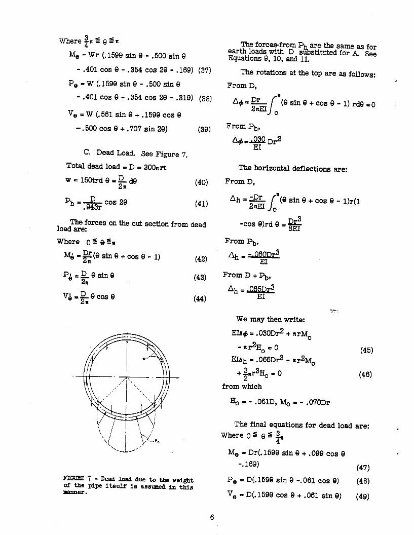
C. D.ead Load. See Figure 7.
Total dead load = D = 3OO,,rt
W=15otrd8 =k de (40)
%=Dcos 28 .943r (41)
The forces on the cut section from dead load are:
Where 0 g @&
q = $Z(e sin 8 + cos 8 - n
1)
PI 3 @sine e 2n
v~=~ec0se
(42)
(43)
(44
FIGURE 7 -Dead loadduetotheweight of the pipe iteelf in aeeumed in thif3 nvmner.
6
The forces-from earth loads with D s ?ib
are the same as for
Equations 9, 10, and 11. stilted for A See
The rotations at the top are as follows: 1
From D,
A+=Dr /
n(h3inQ+c0se-1)rdeso t 2nEI 0
From Pb,
A+ -e Dr2
The horizontal deflections are:
From D,
Ah== J
“(e sin 8 + cos 8 - l)r(l 2nEI o
Qs -cos 8)rd 8 = 6EI
From %,
Ah I time
From D + pb,
Ah =, 065r)r3 EI
3?: We may then write:
EIA+ = .030Dr2 + nrMO
2 -nr Ho=0 (45) abh = .065Dr3 - nr2Mo
+ 3nr3Ho = 0 2 (46)
from which
Hp- .061D, lb&~ = - .070Dr
The final equations for dead load are: Where 0 I s 3 Q
7 Me = Dr(. 1598 sin 8 + .OQQ cos 8 1
-. 169) (47)
Pe = D(. 1598 sin 8 -.061 cos e) (48)
%I = D(J598 cos 8 + .061 sin 8) (49)

Where an 2 0 = n
Me = Dr(. 1599 sin 0 - .500 sin 0
- 401 cos 8 -.354 cos 28 -. 169) 60)
P 8 = D(. 1590 sin Q - .561 cos 9
0.500 sin 8 -.354 cos 29) (51) ve = D(.i%e COS 8 -. 500 cos 8 + .561
sin 8 + .707 sin 20) (52) The formulas for Me and V, NOTE: are the same as for water load with D substituted for W. This holds also for bear- ingareasotherthantandin following derivations for dead load this fact will be used,
2. Analysis for Reaction over Central Angle:.
A. Earth Load.
Pt = A cos $9 (53)
1.568r
~=Acos49 .493r 64
Where OS eSgn
M; z .947 A~(COS $61 - cos e) Where znse s *
(55)
ML, r‘- .947 M+ ~08 48 - cos e) (56)
P;=$ M(,andV;=+$$forticondi-
tions of loading except for dead load where PQ f 4 M& See Equation 43. Hereafter the equations for P& and MQ will not be given.
EIA+= 1.623 Ar2 + lrMo
- nr2Ho=0 (57) EIAh = -2.335 As3 - II r2Mo
++r3q -0 (58)
H, = .453A, MO = -.064 Ar
Where OsQs1n 8
M, = ht.947 cos $8 -.494 cos 8 9.517) (59)
P, = A(. $47 COS $8 -.a COS e) (60)
v, = A(.494 sin 8 -. 541 sin 4 e) 0311
Where Ins @ sn 8
Me = or t-.135 cos 4 8 - .494 cos 8
- ,517) (62)
P, = A(-.135 cos 4 8 - .494 cos e) (63)
Ve = A(.541 sin 4 9 + .494 sin Q) (W
B. Water Load.
pb = w cos 48 .493r (65)
Where
s from Pb = -Wr(.135 cos 48
+ ,500 sin 8 + ,207 cos e)
EIA+ - .493 Wr2 + nrMO
- nr2h = 0
u36)
(67)
EIAh = + .860 Wr3 - nr2Mo
3 3 +p- Ho=0
Ho= -.234W, q = -.078Wr
Where 0 = 8 =$I
Ivr, = Wr(-.162 + .084 cos 9
+ .159 8 sin e)
(68)
(69)
P, = W(-.318 + .084 cos 9
+ .159 8 sin Q) (70)
b = W(.O75 sin 8 + .159 8 cos e) (71)
Where Gns 9 dn
M 8 = Wr( -. 162 - .500 sfn 8
+ .159 8 sin 8 - .123 cos 8
- .135 cos 48) (72)
Pe = W(o.318 - .500 sin 9 + .159 8 sin 8
- .123 cos 8 - .135 cos 4e) (73)
7
.
b = W(-,500 cos 0 + .159 8 cos 8
+ ,282 sin 8 + ,541 sin 48)
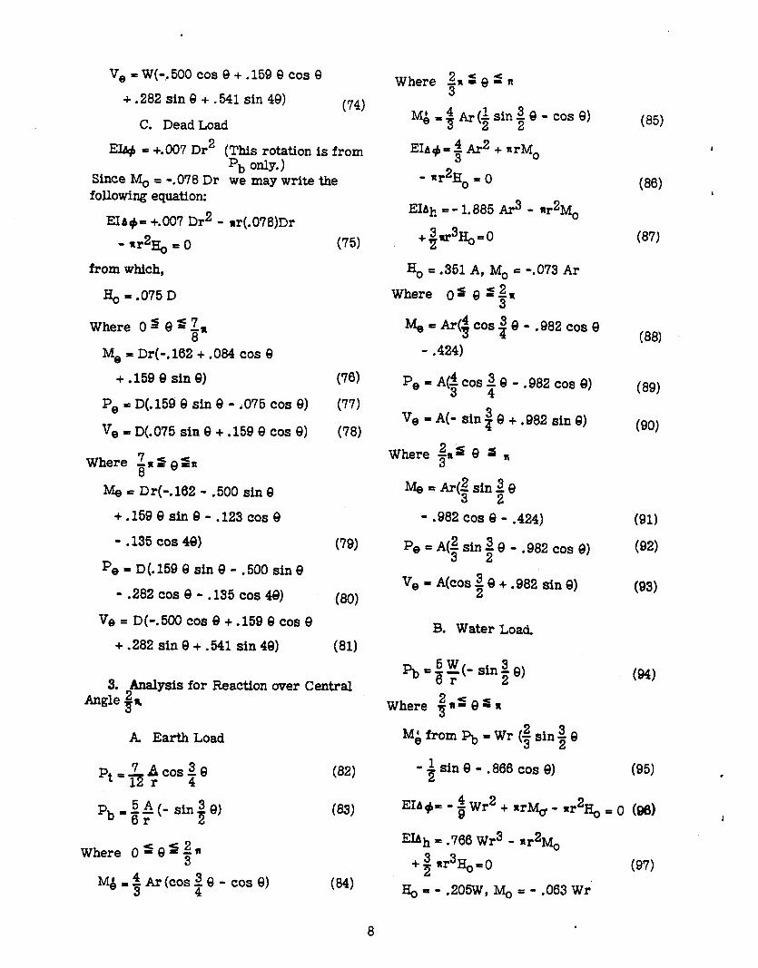
C. Dead Load (74)
EU+ = +.007 Dr2 (This rotation is from
Since MO I -. ‘b only*)
078 Dr we may write the following equation:
EIA+= +.007 Dr2 - ar(.078)Dr
- *r2G = 0
from which,
G = .075 D
Where 0 s 0 2 1, 8
Me = Dr(-. 182 + ,084 cos 8
+.159QsinQ)
Pea = D(.159 8 sin 8 - .075 cos Q)
ve = D(.075 Sin 8 + .159 8 COS e)
Where 2~2 Q&I 8
Nle = Dr(-. 162 - ,500 sin 8
+ .159 8 Sin 8 - .I23 COS 8
- .135 cos 40)
pe = D.(. 159 8 sin 8 - .500 sin 8
- .282 cos 8 - .135 cos 48)
Ve = D(-.500 cos 8 + .159 8 cos 8 +.282sin9+.541sin49)
(75)
(76)
(77)
(78)
(79)
030)
(81)
3. Analysis for Reaction over Central Angle #R
A Earth Load
Pt’&~cosp
‘b’gr 5 * (- sin i e)
(2 Where O=Q=gn
MJ+ Ar (COS $8 - cos e)
Where in f Q s n
IvI&,,$Ar(+sin~e-case)
EIA+=~A~~ +nrM 3 0
- nr2H 0=O EIAh =- 1.885 Ar3 - lr2Mo
+pq)=o
Ho = . 351 A, MO = -.O73 Ar
Where 03 8 -‘$N
~=Ar(~cos3e-.982cose 7 - .424)
P,=A($cos;e-.982cose)
Ve = A(- sin i 8 + .982 sin e)
Where zR4 8 s a 3
M0 = Ar(f sin 5 8 2
- .982 cos 8 - .424)
P,pA(isiniQ-.982cosQ)
ve = Akos $8 + .982 sin e)
B. Water Load.
pb +$(- singe)
Where ins Q=n
M;fromPb=Wr (gsin%Q
- + sin 8 - .866 cos e)
(8%
036)
(8’0
038)
(89)
(90)
(91)
(92)
(93)
w
(95)
EIA+ - $ Wr2 + mr% - nr2Ho = 0 (98)
EIAh = .706 Wr3 - ‘r2Mo
+ $j rr3Ho=0 (97)
Ho=- .205W, MO = - .063 Wr’
8 .

Where 0s 9 s$n
Me = Wr(-.177 + .114 cos 9
+.1598 sine)
*e = W(-.318 + .114 cos 9
(98)
! + .159 9 sin9 (99)
ve = W(.159 9 cos 9 + .046 sin e) (100)
Where 3” -RS eSn
Me = Wr(- .177 - .752 cos 9
+.159esine-.500sine
+ 667 sini e)
Pe = W(- .318 - .752 cos 9
+ .159 0 sin8 - 500 sin e
+ .667 sin! 9)
% = W(.912 sin 9 + .159 8 cos 9
-.500c0s8+~0+)
C. Dead Load.
(101)
(102)
(103)
EI+= & Dr2 + nr(- .063 Dr) -rr H 2 o A0
I&,==‘-.046 D (1W
Vhere 0s 8 d2 3”
Me = Dr(- .177 + ,114 cos 9
+ .I59 8 sin e)
P, = D(. 159 8 sin 8 - .046 cos e)
ve = D(. 159 9 cos 9 + .046 sin 9)
There 2,s@s,, 3
Me = Dr(- .177 - .752 cos 8 +.1599&9-.500sin9
+ ,667 sin; 9)
(105)
(106)
(107)
(108)
9
P e = D(. 159 8 sin 8 - .500 sin 8
+.667 sini - ,912 cos 9) (109)
F3 = D(.912 sin 9 + .159 8 c0s 8
- .500 c0s e+c0s!e) (110)
4. Analysis for Reaction over Central Angle n.
A. EarthLoad
pt+Os 8
*b -2A eAr cos 8
Where 0 s 9 s 3
Mk = + 8 sin 8
(111)
(112)
(113)
Where ;SeS,
MA = A.r(sin e - f sin 8
- p cos 63) (114)
EI+= 4 2 ;;h + Nemo - *r2Ho = 0 (115)
EIbh = -1.773 Ar3 - n r2Mo
+ $r3H 2 ,=o (W
h = .318A, M. = - .087 Ar
Where 0s 9 d;
M, = Ar (.318 8 sin 8 + .318 cos 8
- .405) (117)
P, = A (.318 9 Sin 9 + .318 CO6 9) (118)
v, = .318 A 9 COS 9 (119)
NOTE: Me and P, are symmetrical about the horizontal azis. The values of V, between U andn are numerically equa12but op- posite in sign&m those where 0s 9 =- 2’

+.600
+A00
l .e& Y
0
-300
-A00
M=XKr P=YK V=i!K
For dead load K=D=xxmt For corth load K=A= total weight of earth on pipe For water load K=W=62.4RQ
-“--Stresses indicated ore +
COEFFICIENTS FOR M,, Pe AND V, FOR ;EARING AREA WITH CENTRAL ANGLE= g
10

B. Wecer Load.
pb~2Jbose (120)
Where ;=9=,
M;fromF,=!$ #sine-9sin9
- cos 63)
EIA,j,= -.363 Wr2 + nrMo
- nr2% = 0
ElAh = .613 Wr3 - q”Mo
+3& .=o 2 0
Ho=-. 159W , MO = - .044 Wr
Where 01 9’-;
Me = Wr (39 cos 8 + .I59 8 sine
- .203)
pe =w(.159~0~e+.i59e~ine
- .318)
ve = w (. 159 8 cos 8)
Where ?J ’ 9 ’ R
022) Ebb=. 136 Dr2 + nr(-.044 Dr)
- nr2Ho = 0
qyo
(123) Where 0 s 9 s 5
Me = Dr(.159cos9+.1599sine
- .203) 032)
Pe = D (. 159 9 sin 9) (133)
L =D(.i59ec0se) 034)
(125)
(126)
Where ; s-8 %I
Me=Dr(-.159cos9-.1599sin9
+.500 sin 8 - ,203) (135)
pe = D (- .318 cos 9 - ,159 9 sin 8
+ .500 sin e) (136’
V 0 = D (.500 cos 8 - .159 8 cos e) (137)
Me =Wr(-.159cose-.1599sin9
+ ,500 sin 8 - .203) (127)
1
pe =w (- .159 cos 8 - .159 8 sin 8
+ .500 sin 9 - .318)
ve = w (.500 cos 8
-.1598~0se)
C. Dead Load.
bW
f 1?9)
(130)
(131)
+.600
+.400
+.200 Y
.O
-.200
-400
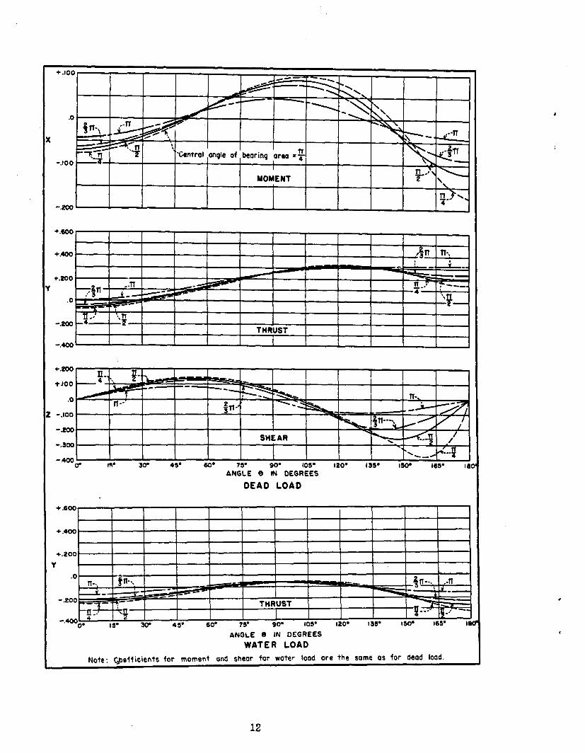
.~ -_ ANGLE 9 IN DEGREES
Y
ANGLE 8 IN DEGREES WATER LOAD
I Note: Qefficients for moment and shear for water load ore the same as for dead load.
12

.
+.600 +.600
+.400 +.400
+.too +.too
Y I
.O .O
-.eoo -.eoo
- ,400 - ,400
---
ANGLE 8 IN DESSEES
EARTH LOAD
(Dead load = XDt Me=jEorth lood =XAr
(Water lood =XWr
(Dead load = YD Pe= 4Eorth load = YA
LWoter load = YW
[Dead lood = Z D Ve= jEorth load = ZA
(Water lood = Z W
COEFFICIENTS FOR Me, PO AND Ve FOR BEARING AREA WITH CENTRAL ANGLES =e,f, +f AND ll
QPO 066-714
13
