stress absorbing membrane interlayer (sami)
TRANSCRIPT

11ATER I AL I NFORI1AT I ON REPORT 50
STRESS ABSORBING MEMBRANE INTERLAYER (S.A.11.1.)
CONSTRUCTION REPORT
by
J.A. Cooper, D.F. Lynch and R.C. Aquin
April 1983


-<:: TO
_~lllh IJ.'", J,I"" III Ii I
),~~.,n. ,c"
{
A
(
T
T L
X' "
1\
North RIJ~~- '31
'If " I'll:
'" ;',-~r VI"
_ l'r=:C'=Ir=--_=-v ; 3 )
!'i
HI!" ~,j, -;-, -'----:----l,--',f, --lIB
J.hun, rar1 Ik.<h
> , . : , , ., ,
w
.' •
" ,
'"
,
• >'
< ., w,
"'
E
-;".=-
T , R
-iT '-, !l-- _~- ~--_==--t BI\'!h~5WL)oJ
-
l_ "
T,c" Tac~y PI.
M,(ch,lll'o,n: ._
TO CHATHAM> >'",,"' ''\,
\",de""
01" i, Ii: ~----'-""L~"""",,, M"!UI.
1\",
'x
'1111
VII
--
Pel •• Potnl
( i i )

ABSTRACT
The reappearance of cracks through hot mix asphaltic concrete
pavements over Portland cement concrete pavements has been a concern
for several years. Current methods of attempting to overcome the
situation have not been entirely satisfactory and there is a continuing
need to find a better method of deal ing ",lith the problem.
A method of reducing cracking has been developed by Sahuaro
Petroleum and Asphalt of Phoenix, Arizona. This method is known as a
Stress Absorbing Membrane Inter1ayer (S.A.M.I.). A S.A.M.I. is a
single surface treatment 13 mm in thickness, consisting of a sprayed
application of an asphalt and rubber binder followed by an application
of heated stone chips. The binder is mixed on the job site and
consists of a blend of 80% asphalt cement and 20% crumb rubber.
This report describes the app1 ication of a S.A.11.1., in t1ay of 1982,
onto a badly cracked concrete pavement which was constructed in 1967
on King's Highway 77. A brief description of blending, application
and construction procedures is included as well as observations
regarding performance.
It has been concluded that the S.A.f1.1. has not prevented
reflection cracks from reappearing in the new pavement over the expansion
joints. HOi-Jever, transverse cracks betv1een the expansion joints have
not reappeared. A small amount of centreline cracking in the nei-J
pavement has occurred. There \oJere no unusual problems when applying
the S.A.H.I. to the concrete pavement. On the basis of the evidence to
date, it is recommended that no further S.A.M.I. installations be
constructed unti 1 further performance evaluations have been made of
the work on Highway 77.
( i )
Co.NTENTS
ABSTRACT
I NTRo.DUCT I o.N
Description
EXISTING Co.NCRETE PAVEMENT
RESURFACING DESIGN RECo.MMENDATlo.NS
Co.NTRACTo.R
11ATERI ALS
EQUIPMENT
Co.NSTRUCTlo.N
Preparation
Asphalt/Rubber Binder - Mixing and Reaction
Spraying the Binder
Spreading the Aggregate
Rol I ing the Aggregate
Sweeping the Surface
Traffic Control
Comments
Hot Mix Paving
Paving Operation
Condition of SAMI
Paving o.ver the SAMI
PERFo.RMANCE TO. DATE
SUMMARY o.F o.BSERVATlo.NS
Co.NCLUSlo.NS
RECo.MMENDATlo.NS
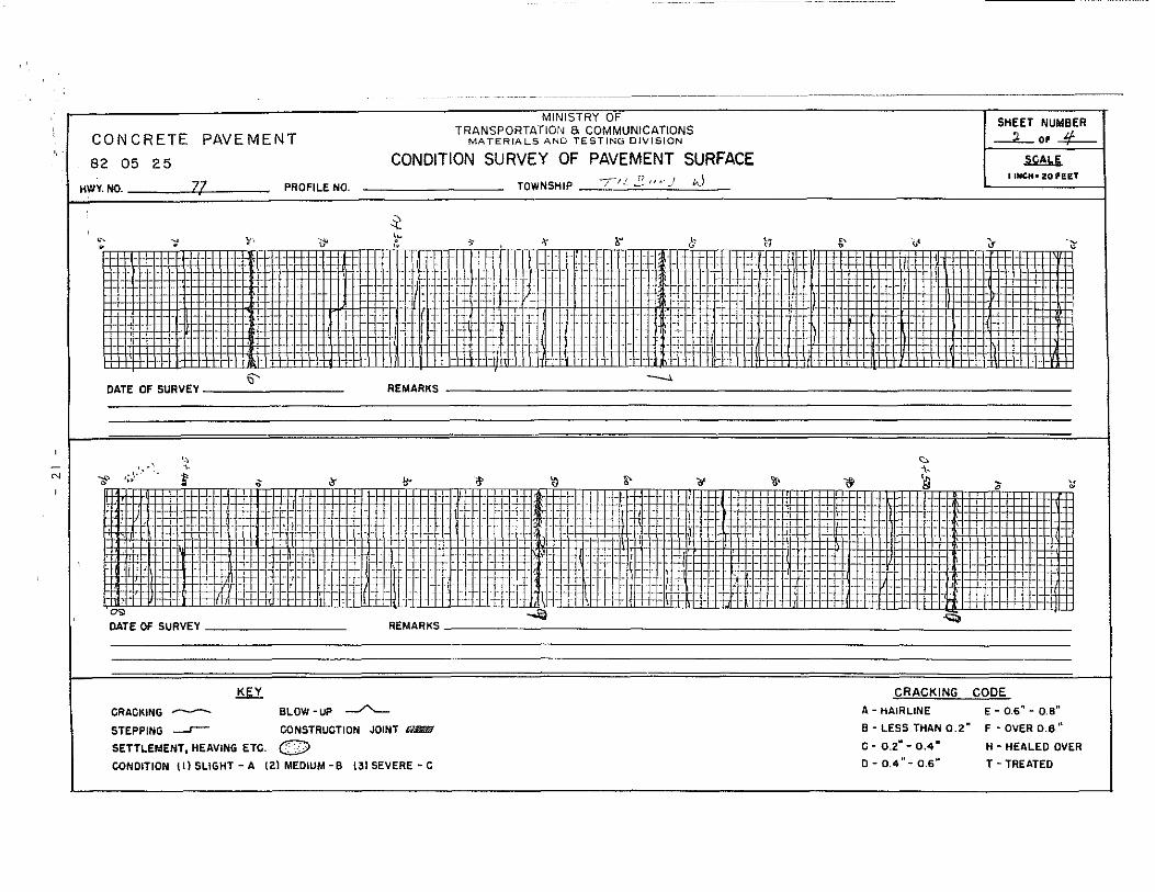
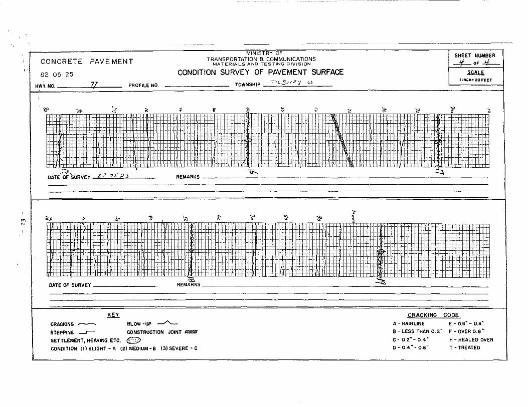
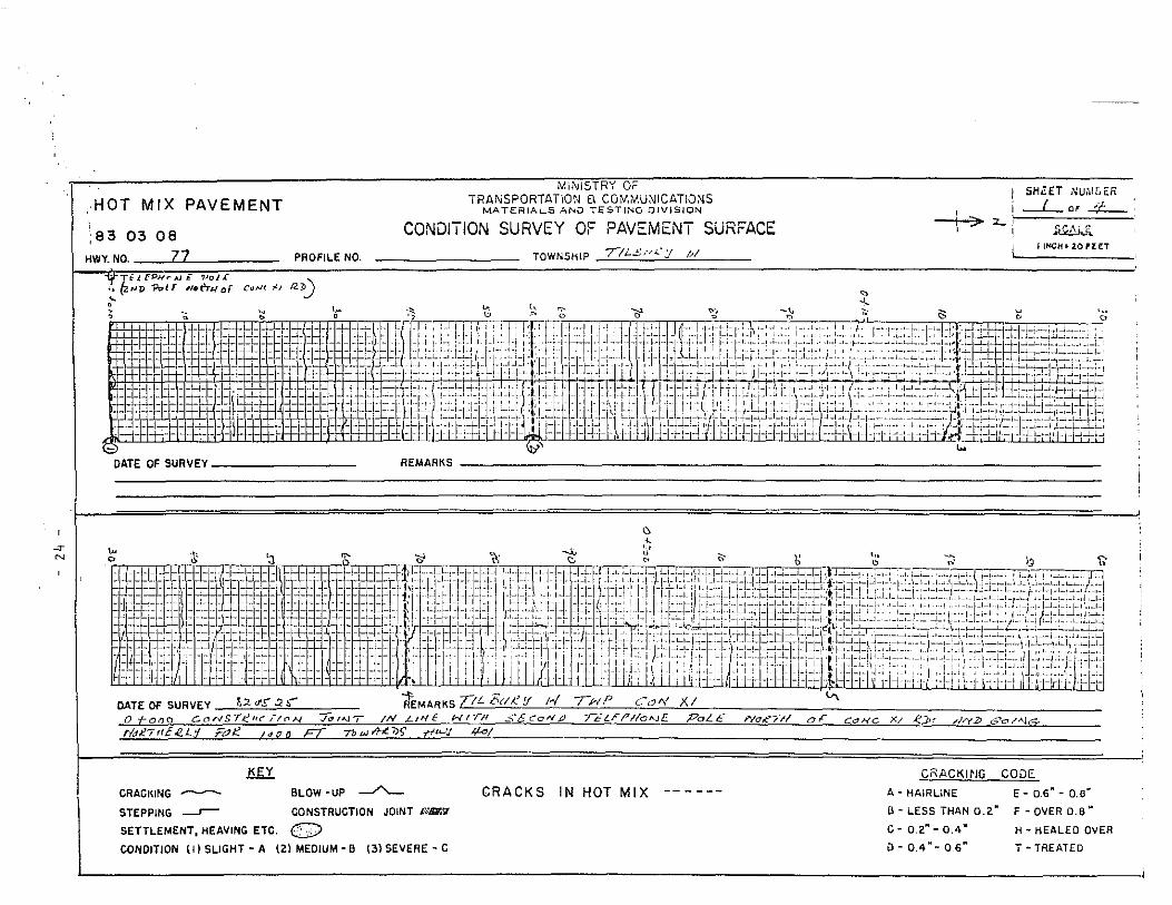
APPENDIX A, Condition Survey of Pavement Surface
APPENDIX B, Special Provision
APPENDIX C, Binder Viscosity
APPENDIX D, Field Sampl ing to Determine the Amount of Binder and Aggregate Appl ied to the Road
( iii)
2
2
3
5
5
5
6
6
8
8
8
10.
10.
10
10.
13
14
14
14
14
17
18
18
20.
28
34
36

I NTRODUCT I ON
- I -
STRESS ABSORBING MEMBRANE INTERLAYER
(S.A.M.I.)
CONSTRUCTION REPORT
by J.A. Cooper, D.F. Lynch and R.C. Aquin
The reappearance of cracks through hot mix asphaltic concrete
resurfacing over Portland cement concrete pavements has been an on
going problem. The standard method of overlaying concrete pavement
with hot mix is to level ,.Ji th HL-2 or a modified HL-4 or 8, followed
by a binder course and a wearing course. Total pavement thickness
ranges from 60 to 130 mm, depending on the condition of the concrete
pavement, location, AADT and other pertinent design factors.
The purpose of the HL-2 is to waterproof and level the existing
concrete pavement and, to some degree, retard reflection cracking
through the ne\'1 hot mix. The ability of the HL-2 to minimize reflection
cracking has not been entirely satisfactory and a more effective means
of reducing the amount of reflection cracking is desirable.
A method of reducing cracking has been developed by Sahuaro
Petroleum and Asphalt of Phoenix, Arizona. This method is known as a
Stress Absorbing Membrane Interlayer (S.A.M.I.) and is claimed by
Sahuaro to be flexible enough to bridge cracks and waterproof the
concrete pavement. This report outlines the construction of a Stress
Absorbing Membrane Interlayer on King's Highway 77 in May of 1982
prior to resurfacing with hot mix asphaltic concrete. For future
reference, a detailed map crack survey was completed over a control
section of the concrete pavement before the construction of the S.A.M.I.
The main purpose in constructing the S.A.M.l. \'ias to assess its effective
ness in reducing reflection cracking through the new hot mix resurfacing
and to determine any appl ication or traffic problems during construction.

- 2 -
Deser i pt ion
A S.A.M.I. is a single surface treatment 13 mm in thickness consisting
of a sprayed appl ication of a specially formulated asphalt and rubber
binder, followed by an appJ leation of heated stone chips.
To achieve the desired flexibility, a soft asphalt cement is mixed
with approximately 20% by weight of crumb rubber in a blending plant on
the job site. The crumb rubber is produced by grinding up used tires
and peelings from retreaded tires. The ground rubber is then placed in
plastic bags and transported to the job site and dumped into a hopper at
the side of the blending plant. From there it is fed to the mixer where
it is combined with the asphalt cement at 210°C.
As the rubber mixes with the asphalt cement, it melts and expands
causing the mixture (binder) both to become more viscous and to cool.
The mixing process is carried out for approximately 20 minutes and then
the asphalt/rubber binder is pumped into either a separate storage tank
or directly into a specially constructed asphalt distributor capable of
spraying the high viscosity asphalt/rubber binder directly onto the
concrete pavement at the desired rate of app1 ication.
EXISTING CONCRETE PAVEMENT
The section of Highway 77 where the S.A.M. I. was constructed is
straight and level and begins at the Comber south limits and proceeds
southerly 8.7 km. The existing pavement placed in 1967 consists of a
concrete slab, 6.7 m in width, 175 mm in thickness, which is reinforced
with dovJels. Expansion joint spacing is at 18 m + intervals (Figure 1).
Cores taken through the pavement reveal that the lower 50 mm of concrete
has cracked extensively and at the joints the lovler 100 mm has reverted
to aggregate. The concrete slab is underlain with 150 mm of granular IAI
overlying approximately 100 mm of granular sub-base.
The entire 8.7 km of concrete pavement was cracked at the expansion
joints and transversely at intervals between the expansion joints.
There was 0 cracking of the expansion joints at centreline and at the

- 3 -
- ~ --- .
edge of pavement. The expansion joints were moderately to severely
spalled, Itlith many joint failures (see Figure 2). Some relief sawing
had been done by MTe maintenance forces. Blow-ups that had occurred
were patched with hot or cold mix. The spalled areas had been sealed
with emulsion and chips, however, this ~'1as only partially effective and
deterioration has continued. Most of the spalled areas, including those
along centreline, were patched with cold mix just prior to placing the
S.A.M. I. Transverse cracks occurred throughout the section between the
joints (Figure 3). A map crack survey carried out just prior to
construction of the S.A.M.I. indicated an average of 40 m + of transverse
cracking between expansion Joints (see Appendix A).
Due to poor drainage and wet saturated conditions in the sub-base
and subgrade, 100 mm diameter perforated plastic pipe was installed along
both pavement edges for the entire length of the concrete pavement in
1978. It was hoped that this would improve drainage and retard the rapid
deterioration of the underside of the pavement. Recent examination of
the outlets from the pipe has confirmed that the pipe is removing water
as intended and should assist in retarding pavement deterioration to
some extent.
RESURFACING DESIGN RECOMMENDATIONS
In vie\-J of the concrete pavement conditions, the following re
commendations were made for resurfacing this section of pavement:
25 mm HL-2 Leve 11 i ng Course
40 mm HL-4 Binder Course
40 mm HL-4 Surface Course
A contract (81-77) to resurface the concrete pavement was awarded in
January, 1982, based on the above recommendations. Prior to the commence
ment of the resurfacing operation, it was decided to investigate the cost
of constructing a S.A.M. I. in lieu of the HL-2 levelling course. A
Special Provision was prepared (see Appendix B) and sent to the contractor
to obtain the cost of constructing the S.A.M. I.

- 4 -
;,,,,,":,~ ... :~<.-~~ .~'::. .'';.
Figure I: Hwy. 77 Concrete Pavement Before SAMI
Figure 2: Typical Expansion Joint in Concrete Pavement
Figure 3: Typical Crack Between Expansion Joints
- 5 -
It vJas determined that there v'JOuld be an estimated saving to the
Ministry of approximately $47,000 by placing the S.A.M.I. when compared
to placing the HL-2 for the section in question. On the basis of the
anticipated cost saving and the Ministry1s desire to assess the benefits
of the S.A.M. I. system, it was decided to proceed with the construction
of the S.A.M.I.
CONTRACTOR
The general contractor for the work was R.E. Van Gassen Ltd.,
P.O. Box 900, Chatham, Ontario, who subcontracted the construction of
the S.A.M.I. to Sahuaro Petroleum and Asphalt Co., Canadian Division,
14322 Magdalen Ave., Whiterock, B.C. The work was carried out during
the last week of May, 1982.
MATERIALS
The fol1m·Jing materials \!-Jere used to produce the S.A.M.I. as per the
Special Provision (Appendix B):
Asphalt Cement lSD/ZOO penetration grade obtained from McAsphalt
Industries, Toronto, Ontario.
Asphalt Modifier not required.
Rubber
Diluent
Aggregate
EQUIPMENT
Type I I (Ouramesh 1030) obtained from Dura Undercushions
Ltd., Montreal, Quebec.
Kerosene obtained locally at Chatham, Ontario.
HL-3 coarse aggregate obtained from Canada Crushed
Stone, Dundas, Ontario. It was heated at Chatham in
Van Gassen's hot mix plant.
The follO\-Jing equipment ~'Jas used to complete the work:

- 6 -
2 - Bearcat asphalt distributors, specially modified to spray the rubberized
binder; obtained from Sahuaro Asphalt and Petroleum Co., Phoenix,
Arizona.
I - Heater blender, specially manufactured to produce the rubberized
binder, obtained from Sahuaro Asphalt and Petroleum Co., Phoenix,
Arizona.
1 - Storage tank for kerosene.
I - Flaherty self-propelled chip spreader obtained on rental from Spinks
Sand and Gravel, Leamington, Ontario.
2 - Self-propelled rubber-tired rollers (8.0 tonne) obtained from
Van Gassen Ltd.
I - Self-propelled rubber-tired roller (8.0 tonne) obtained from Spinks
Sand and Gravel, Leamington, Ontario.
CONSTRUCTION
Preparation
Repairs were made to the existing concrete pavement where longitudinal
and transverse joints were in exceptionally poor condition and areas of
severe cracking and spa1 ling had occurred. Remedial work in these areas
was carried out using cold mix patching materials.
The concrete pavement was swept clean of all dust, debris, dirt and
loose material by means of a power broom the day prior to commencement
of the appl ication of the S.A.M. I. The surface was exceptional 1y clean,
and on the advice of Sahuaro the spraying of the tack coat was judged
unnecessary and therefore el iminated.
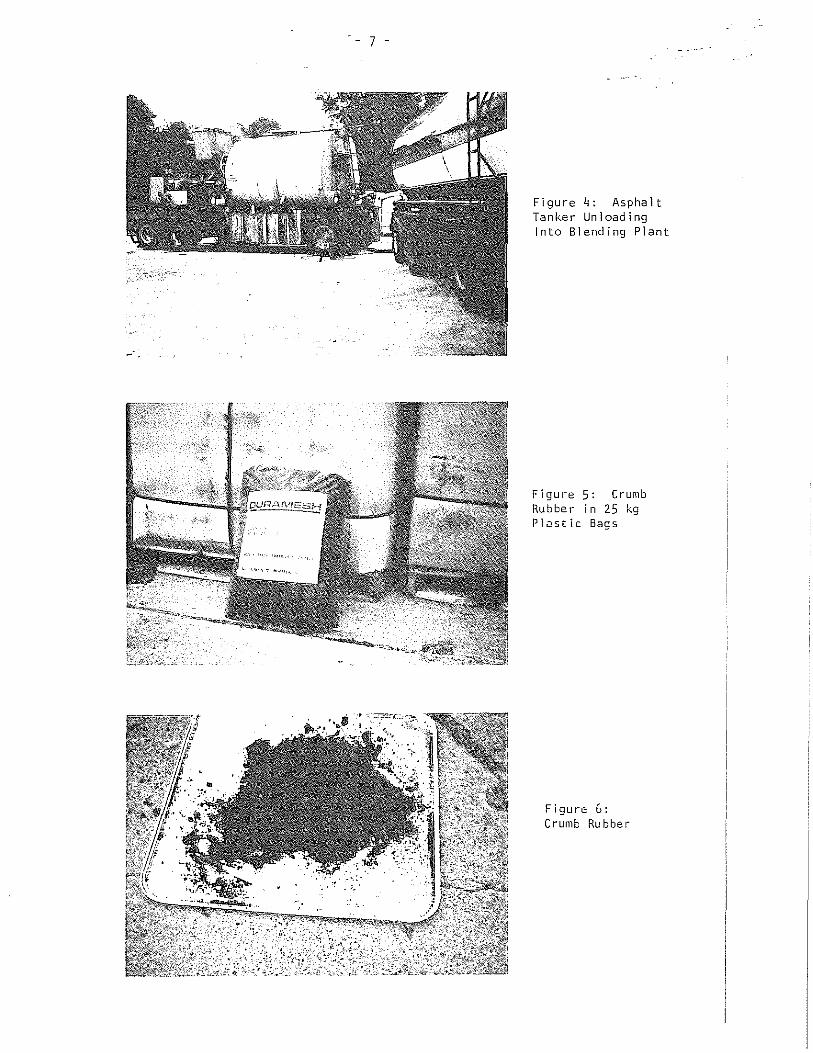
- 7 -
Figure q: Asphalt Tanker Unloading Into Blending Plant
Figure 5: Crumb Rubber in 25 kg Plastic Bags
Figure 6: Crumb Rubber

- 8 -
Asphalt/Rubber Binder - Mixing and Reaction
The 150/200 pen. asphalt cement was pumped from the tanker into a
heated storage tank on the blender where it was heated to 2100 e. The
asphalt cement (150/200) was then pumped into the blender unit where the
granulated rubber was added. A meter indicated the gallons of asphalt
cement in the blender and the desired amount of rubber was added to the
blender by means of a bucket elevator at the side of the unit. The
asphalt and rubber were mixed in the blender for 25 minutes and then
pumped into a distributor resulting in a temperature drop of the binder
to 165°C. The binder was held in the distributor for approximately
60 minutes until the reaction between the asphalt and rubber was complete
and the desired viscosity was reached. The viscosity of the binder was
checked on site with a Haake Viscotester. Approximately three percent
kerosene was then added to the binder to obtain the desired viscosity
for spraying. A special auger running the length of the distributor tank
and a recirculating pump continued to mix the binder until it waS sprayed.
Spraying the Binder
The binder was sprayed across one lane at a time onto the concrete
pavement by the distributor. The temperature of the binder immediately
after spraying was approximately ISSoC. The amount of binder waS closely
monitored by a sophisticated panel in the driver1s cab. The desired
application rate waS 2.5 kg/m2 . Standard surface treatment techniques
were used for the transverse joints and the longitudinal centreline joint.
No problem l-..ras observed ItJhen the hot binder was sprayed on the cold
patching material.
Spreading the Aggregate
The aggregate was spread immediately using the self-propelled chip
spreader. The desired appl ication rate was 16.5 kg/m2 . The aggregate
had been trucked by tractor trailers from Chatham, Ontario, where it had
been heated in Van Gassen1s hot mix plant. It was dumped on the job site
and loaded into tandem dump trucks and taken to the chip spreader. The
temperature of the aggregate was taken as it was being spread and was
found to be 140-1500 C.

- 9 -
Figure 7: Adding Crumb Rubber to Blending Plant
Figure 8: Sweeping Concrete Pavement Prior to Applying Binder
Figure 9: Bearcat Distributor Spraying Binder

- 10 -
The purpose in heating the aggregate was to ensure that the
aggregate was completely dry and to assist in obtaining the best
possible bond between the binder and the aggregate.
Roll ing the Aggregate
Immediately upon spreading, the aggregate was ral led using the
three rubber-tired rollers. Each roller made two complete passes. It
is extremely important that there be no time lag between spraying,
spreading and rolling to ensure best results as the binder cools quickly.
Sweeping the Surface
Approximately two hours after the roll 1n9 had been completed, the
S.A.M.I. was swept ~ ... ith a power broom to remove any excess aggregate
before being opened to traffic. Spraying was completed each day about
16:00 hours so that sweeping was completed for evening traffic.
Traffic Control
Pick up trucks with flashing signs were used at each end of the
worle Flagpersons, about 1 km apart, wi th 2-vJay radios allmved traffic
to pass alternately in each direction in the open lane. Traffic was
not significantly delayed.
Comments
No particular difficulties were encountered on the job and the work
proceeded at a very productive rate. The application rates of the binder
and aggregate were checked on the job site using 50 cm square cardboard
trays and a portable digital scale, as well as totalling the quantities of
all materials used and calculating the area covered. Field sampling to
determine the viscosity of the binder prior to spraying was carried out
as described in Appendix C. Field sampling to determine the amount of
binder and aggregate appl ied to the pavement was carried out as described
in Appendix D.

- I I -
Figure 10: Spreader Applying Heated Cover Agg ,-ega te
Figure 11: Taking Temperature of Cover Aggregate
Figure 12: Roll ing Cove r Agg rega te

- 12 -
Figure 13: SAMI Completed on the Right
Figure I~: Close-up of Completed SAMI
Figure 15: Placing HL-~ Binder Over SAMI
- 13 -
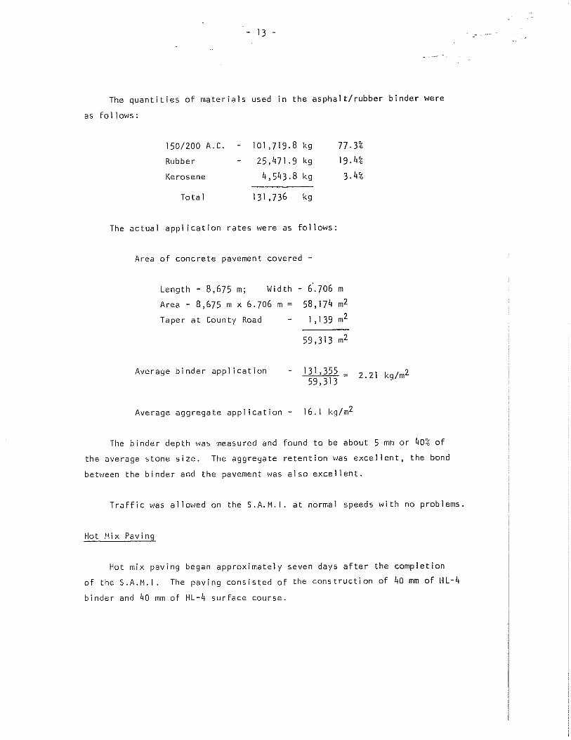
The quantities of materials used in the asphalt/rubber binder were
as follows:
150/200 A. c. 101,719.8 kg 77.3% Rubber 25,101.9 kg 19.4%
Kerosene 4,543.8 kg 3.4%
Total 131,736 kg
The actual applleation rates were as follows:
Area of concrete pavement covered -
Length - 8,675 m; Wid th - 6·.706 m
Area - 8,675 m x 6.706 m = 58,174 m2
Taper at County Road
Average binder app1leation
1,139 m2
59,313 m2
131,355 59,313
Average aggregate appl ication - 16.1 kg/m2
2.21 kg/m2
The binder depth was measured and found to be about 5 mm or ~O% of
the average stone size. The aggregate retention was excellent, the bond
between the binder and the pavement was also excellent.
Traffic ~..,as allm..;ed on the S.A.M.I. at normal speeds with no problems.
Hot Nix Paving
Hot mix paving began approximately seven days after the completion
of the S.A.M.I. The paving consisted of the construction of 40 mm of HL-4
binder and qQ mm of HL-4 surface course.

- .14 -
Paving Operation
The contractor's asphalt plant was located south of Chatham, 40 km
from the job site.
Paving equipment consisted of:
- Cedarapids mechanical paver ~."ith track and 40' ski,
- Bros VM 268 tandem steel-tired vibratory roller,
Tandem and tractor trailer trucks as required.
Condition of the S.A.M.I.
The S.A.M.I. was in excellent condition prior to paving. It was noted
that trucks hauling the HL-4 hot mix did not damage the surface of the
S.A.M.I. when turning; also the Cedarapids track paver did not damage
the S.A.M.I. which was well bonded to the concrete surface. There V'Jere
no cracks or joints showing through the S.A.M. I. at the time of paving.
Paving Over the S.A.M.I.
There were no difficulties encountered paving over the S.A.M. I. and
there was no slippage or movement of the hot mix mat during laying or
rolling. The paving operation proceeded in the normal fashion at the
usual rate with no problems. The mix was laid to the desired thickness
and density and bonded well to the S.A.M.I. The surface course was
completed in July J982 and no reflection cracking was evident at that time.
PERFORMANCE TO DATE
The finished pavement was examined on 82 11 24 prior to experiencing
any ambient temperatures below OOC. The riding qualities of the pavement
were very good, hm'Jever, cracking at the expansion joints Itlas already
evident.

- 15 -
Figure 16: SAMI (Foreground) and HL-q Binder
Figure 17: Hwy. 77 Three Months After Paving

- 16 -
Figure 18: Typical Crack Over Expansion Joint
Figure 19: Close-up of Typical Crack (3 mm) Over Expansion Joint

- 17 -
In the Village of Comber, the same hot mix overlay was placed over
existing bituminous pavement. There was no transverse cracking evident
in the V i II age on 82 II 2q.
In March, 1983, after the first winter, a detailed crack survey was
taken in the 300 m control section, see Appendix A. There were cracks,
open about 3 mm, at all expansion joints, with some D cracking at centre
line and at the edges of pavement. There was approximately 39 m of
cracking directly over the centrel ine joint in the 300 m control section.
With the exception of 3 m of cracking, there was no intermediate
transverse cracking between the expansion joints.
Six, 15.2 em diameter, cores were taken from the control section in
March 1983, at expansion Joints and between expansion Joints. Examination
of the cores revealed that the S.A.H.I. was broken directly beneath the
crack in the hot mix over the expansion joints. The S.A.M.I. vJas not
broken over the intermediate transverse cracks in the concrete pavement.
The ride was considered good, as assessed in a compact car. A very
sl ight bump \'Jas noticeable at the expansion joints.
SUMMARY OF OBSERVATIONS
(I) Reflection cracks have appeared in the hot mix over all the expansion
joints in the concrete pavement.
(2) Reflection cracks have not appeared in the hot mix over the transverse
cracks between the expansion joints in the concrete pavement.
(31 A smal I amount of reflection cracking has appeared in the hot mix
over the centrel ine joint in the concrete pavement.
(ql The S.A.M.I. membrane has broken OVer the expansion joints.
(5) The ride after one winter is judged good, as assessed in a small car.
- 18 -
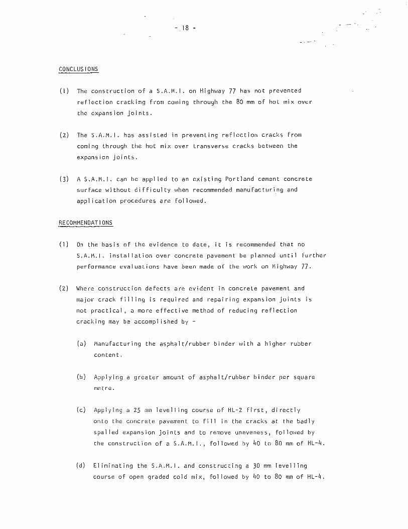
CONCLUS IONS
(I) The construction of a 5 .A.H.I. on Highvlay 77 has not prevented
reflection cracking from coming through the 80 mm of hot mix over
the expansion joints.
(2) The S.A.H.I. has assisted in preventing reflection cracks From
coming through the hot mix over transverse cracks between the
expansion joints.
(3) A S.A.M.I. can be app] led to an existing Portland cement concrete
surFace without difficulty when recommended manufacturing and
application procedures are follm'lled.
RECOHHENDATIONS
(1) On the basis of the evidence to date, it is recommended that no
S.A.M.I. installation over concrete pavement be planned unti 1 further
performance evaluations have been made of the work on Highway 77.
(2) Where construction defects are evident in concrete pavement and
major crack filling is required and repairing expansion joints is
not practical, a more effective method of reducing reflection
cracking may be accompl ished by -
(a) Manufacturing the asphalt/rubber binder with a higher rubber
content.
(b) Applying a greater amount of asphalt/rubber binder per square
me t re.
(c) Applying a 25 mm levelling course of HL-2 first, directly
onto the concrete pavement to fi 11 in the cracks at the badly
spalled expansion joints and to remove uneveness, follm·Jed by
the construction of a S.A.M.I., followed by 40 to 80 mm of HL-4.
(d) EI iminating the S.A.11.1. and constructing a 30 mm level I ing
course of open graded cold mix, followed by 40 to 80 mm of HL-4.

- 19 -
(3) Precoating of the stone chips to prevent dust when spreading the
chips and to assist in more rapid setting should be considered.
(4) Consideration should be given to sealing the cracks in the new hot
mix with hot rubberized asphalt.
ACKiWWLIoUGEMENTS
Special thanks are extended tc the staff of Southwestern Region
for their excel lent co-operation and to the Research and Development
~ranch for their assistance.

o N
'"' x C> z w a. "-
'"'
MINISTRY OF . TRANSPORTATION a COMMUNICATIONS SHEET NUII8ER ,CONCRETE PAVEMENT MATERIALS AND TESTING DIVISION I -Lo.-4:--,82 05 25 CONDITION SURVEY OF PAVEMENT SURFACE I ')0 :z.. ~
... ' . I t=HI ZOPlIET HWY.OO. 77 PROFILE NO. TOWNSHIP "TIU,·l.:/ W
VT€ l F'ONr #oJ E PoJ £ ,~ (l1.J""D 'PolE ffltbH M CQN~"f.1 all '\ ~ J ~ . ~ -\. ~ 'ii t \,>" ~ 'ti s- 6' C5 ~ ~ - ~ 't ~
. ": .. ::= .. : '~~:'r :~'l~V:·.::··:,::··:r. ·.ft :.:'::' .. ~., '.: .: .... "r . tt ";_.. ,····,·F'.:. ..= .... " .
- - =::=. J:L-- ~~_ ,-\.- .. --- - __ I ~ __ - ___ ~_ _ _ ~ :: - -
~ ~
DATE OF SURVEY REMARKS ------------------------------------------------------________________________ _
(:> , ); ~ 'd '" <i ~ 't ~ il- 1: ~ ~ 1'1 S
I - r - ..•. _-- - -- ----- - - - - - .. - \- - _. _._-_. - --- - -- -- - - - --= - - - --- --- ~- - ... - - _.. - - - - -
:: - - - - :: -::. ~: - -::: I~ ~ - ~ -~:: - ~:: =- -: ~ - - - - - - - - .- -, - - - - - - : :::
-- -- r r--' - -_.. -- .. --_. -- _ .. _- --- - - - "
:. =::=1*. :' .. ·::;;:,~l~!=::··::·.: -::==:·:frjr:-::--:-:·~:==::= =:=:: -- .:::=: .': = .... DATE OF SURVEY ~:>'d'S".2" /lEMARKSTlLEtl"!! W IHP Co,", XI '"
o roaQ CClrVsTI:!II(' ,{ClN -I"/~, /N Llr/£ kITH .:.-ECoNp TELEPHo"'J£. PoLe Na,tf-;H o,c CaNe XI .eJ>~ C;'y.z; G'ClrAlG-rldKlff£JZLY rat:. /4t10 FT 7b, .• dr-£~q .ffV.J:I ~I
~ CRACKING CODE
CRACKING --- BLOW - UP ~ A - HAIRLINE E - 0.6" - 0.8"
STEPPING ~ CONSTRUCTION JOINT _ B - LESS THAN 0.2" F' OVER 0.8"
SETTLEMENT, HEAVING ETC. @) C - 0.2" - 0.4" H - HEALED ovER
CONDITION (I) SLIGHT - A (2) MEDIUM - B (3) SEVERE - C D - 0.4" - 0.6" T • TREATED
N
CONCRETE PAVEMENT
82 05 25
HillY. NO. 77 PROFILE NO.
MINISTRY OF TRANSPORTATION a COMMUNICATIONS
MATERIALS AND TESTING DIVISION
CONDITION SURVEY OF PAVEMENT SURFACE
TOWNSHIP -l-Ii..!!'''-j t-..J
::c ~ );' (~! \J ~ '","
SHEET NUMBER
-Lo, -4--~
IIUCH' ZO,e:e:T
"' '-imM!.wmrt[~llj#fltIM~i' " rJThnwmM~11:IJ.~~#r:1mm!.· ;
S' DATE Of SURVEY ________ _
~ I;~\>·'- " ~ :!' ~ iI'
-=IUlI1ffi' . =~-ttt1. -~1j:ttl_ -J- .. __ ... "r! 1 - -T'- r . 11[---;-1
-I
.. ~
REMARKS
!<- &
ll:~' , i-Frr'
,,·JHj!HHfltl~r ---..l
\) Ii' '11
~:H li- "1'---
11111111+H Ir-iT" 1-"
-., .. ~J#. rJ~[ (, =~*:~·Il. JP:,_·-rE, 1 I. r =~ +1-= fH---·-
" "1'-
'6'
-'4
-I-'):I:I:B I-. _ •. 1.. _____ [I.,;
'li' m,:FF #EEE
'll=E
eo. i-
'El c
-j4-n-EI-I-I-' =:r=o=-u:.-
" •
"" DATE OF SURVEY ________ _ REMARKS -.l;) -Q;,
CRACKING --
STEPPING --r-
.lS.ll BLOW-UP ~
CONSTRUCTION JOINT IH.IliIii1
SETTLEMENT, HEAVING ETC. CD CONDITION (il SLIGHT - A (21 MEDIUM -B (31 SEVERE - C
CRACKING CODE
A - HAIRLINE E - 0.6" - o.a" B - LESS THAN 0.2" F - OVER 0.8"
C - 0.2" - 0.4 II
0- 0.4"- 0.6"
H - HEALED OVER
T - TREATED

N N
CONCRETE PAVEMENT .82 05 25
HWY.NO. 71 PROFILE NO.
MINISTRY OF TRANSPORTATION 8 COMMUNICATIONS
MATERIALS AND TESTING DIVISION
CONDITION SURVEY OF PAVEMENT SURFACE TOWNSHIP TIL 3l/i! J IJ
SHEET NUMBER __ 3_ OF -'I---
~ IINCH-ZOnET
;,> IS' ~
-~ "" "ti' ,~
o "' • o ~ ~
mllim __ c
il- t '\J
-'-''hl:l:I::!±~:I±[l::~r!!
r. m·,· ~
·v·: :::\.. -- --F ~- ::~:- --:~--'nl-I--I' "1";1#--'-il+' ~_.---- _.
-.J~r~-·--:::::-: ~ ~::::::--:::- -:~ ~
-I" 1:1:11--'J: __ ~:rr r:c - -.-,-+ .-~
DATE OF SURVEY ________ _ REMARKS ____________________________________________________________________ __
~ ~ 1>" ~ ~ ~ a ~ ~ -~ N f' "'b' ~
111III1IJI.[I11iM=lfD~.=r~wllf~iilml_lBIam~I~UtM_ 1+ IT'-1-' -. tT il' HH~~ffl:1-l1i J " -- -'-'r -"'~'tl=1f
:!=T:~-'-
DATE OF SURVEY i'» REMARKS -¥
CRACKING --
STEPPING ~
.!$ll BLOW-UP ~
CONSTRUCTION JOINT _
SETTLEMENT I HEAVING ETC. CD CONDITION (I) SLIGHT - A (2) MEDIUM - B (3) SEVERE - C
!ttl::'t:::·_·--,~!=I=I= -i""-
CRACKING CODE
A - HAIRLINE E - 0.6" - O.S"
B - LESS THAN 0.2" F - OVER 0.8"
G - O.Z" - 0.4"
0- 0.4"- 0.6"
H - HEALED OVER
T - TREATED
M N
CONCRETE PAVEMENT
82 05 25
MINISTRY OF TRANSPORTATION a COMMUNICATIONS
MATERIALS AND TESTING DIVISION
CONDITION SURVEY OF PAVEMENT SURFACE
I SHEET NUMBER . -#-0. 4--~
;IL.5(/R y w liNCH- zOPlEn
HWY.NO.
~ ';§>
Ii
71
I'.-~--.......
',:t '"
PROFILE NO,
~
DATE' ';SURVEY 6-:;J 0' -.;.> ) -
;;;;.2 .I" Ii- l'
TOWNSHIP
~ l< ... :;. Ii'
-J:_I'EP-=f11-1= ~ = I '-,rt,~,+WI'I-I=I~'-' =G __ =,:f:r ~ +-~.; ::: l-; 1L~-'---:-1:[ + it- -1- "----t--ii--i-- + -1+- T·- - --1
-:I:~mT: jjj ~tl:t~::J~·,. ::*: :'~-~~F~rl!-J!l -.- -:~; -: tfi 1=1-\,-::....' ',,: -::: - -, - =,', , --: :j:i=f:FFttt -1+1/-' -F~: ::-; : _:_::--R-- -.-
-'-'1-
\j' "
REMARKS ~ ~
'l: 'G !:' i;' 'I< ~
It)- - -- ':-:-- : ,_:::- ::t-l,1=~ _.:Jr~:::-- 3~;-- -: _:-:::-:: If :-: --=:- -=: __ ::- _H 1-- -. -- - ---- " - ,- { -ft~tl-' - "- =~ - - -:t - ---- +: - --- '" - --- - --H- - - _-: ____ : : _ - __ :: .:- ::::-:- ___ - ,- __ --- ,~--- __ -n - " ~' -::- __ -- _:- : __ ::--::: __ ,
'I=ft :-------:---::_ ::-:~: :::: : _:-::~J::j:,::'"::-->-t::::==::: - __ -:>:- 1_:-(::- ::- ::/:L- t -~ -- :-:-::~-:-:--I - : -=+: ---- ,=-.- -1:J:~rl=l-t -::--1 ::- =:--:1::1::::=_=:==>=-T:::-:::::~--:\J:!II:-=i::-, EEE -1--- - j!:--- r- ----- -Trl-+-I-~- -- -- - i- - - -- -t -+--- - ._- --- r---------------I-r-l=!=+ -
<;:; -DATE OF SURVEY ________ _ REMARKS ~
CRACKING -
STEPPING ----r-
llY. BLOW - UP --""-
CONSTRUCTION JOINT_
SETTLEMENT, HEAVING ETC, @ CONDITION (I) SLIGHT - A (2) MEDIUM - B (3) SEVERE - C
CRACKING CODE
A - HAIRLINE E - O.S" - 0.8"
B - LESS THAN O,Z" F - OVER 0,8"
c- 0.2"- 0.4"
0- 0.4"- 0.6"
H - HEALED OVER
T - TREATED
-"" N
.HOT MIX PAVEMENT
;83 03 08 HWY. NO. 77 PROFILE NO.
, ,
DATE OF SURVEY ________ _
... "\! 0 <, '"
DATE Of SURVEY ;.:z. d'S .2 ~
MiNISTRY OF TRANSPORTAT'lON f.I COM",.U~ICATIO~S
MATERIALS AND TESTING QIVISION
CONDITION SURVEY OF PAVEMENT SURFACE TOWNSHIP 7/L,£,/J.: y / .. /
" < ~ ". -:'> " " >
Co'" X/
, ~"-
<"
'"
SH,zET ,~Ui\l[JC:R
-L 0' -4:--' ~I.".r;,
II~H·ZOrlfT
Orono cCJrVs-r/!II("-,-/f"lN -ICIIAj I IN LINE HITI' .::...~cCoNp TElFp//o"-J£ PaLe: i"Iotl!,"1/ 0'< ~tlc_X/ -e;p~ /!,ry2J BOt'AJh-
rl,N!7rf£.l!.Lj FoK. /4()(J FT 7OMlr-tl....!.)9 _-t';tL-<'J ~I
CRACKING --
STEPPING --..r--
.lSll BLOW· UP --""-
CONSTRUCTION JOINT I/lJJil1N
SETTLEMENT, HEAVING ETC. C9 CONDITION III SLIGHT - A l21 MEDIUM - B l31 SEVERE - C
CRACKS IN HOT MIX ------CRACKING CODE
A - HAIRLINE E - 0.6" - 0.0"
B - LESS THAN 0.2" F - OVER O_B"
C - 0.2" - 0.4-
0- 0.4"- 0.6-
H - HEALED ovER
T - TREATED

en N
HOT MIX PAVEMENT
83 03 08
HWY. NO. 77 PROFILE NO.
'~~i"!!5TRY OF P~ANSPORTATIO".' '3 COfl.i:.iUNiCAT10NS
t"lJ\TEH!AL~ Ar-..'D TESTiNG DIVISION
CONDIT!ON SURVEY 0::- ?!\VC:V,E,\T SURFACE
TOWNSH!P ;- II. .!: (1/ J lJ
~
SHEET NUMBER
-2-0' -4-~
liNCH- lO,efT
~, ~ 't, ~ ~: ~:i ;" ~'u-l. ~ .~
c: J:,::,:~:::!-:::!_:::!:,_,_,_, : :--!;' !-:.: :T-T!-;-:~!-!-I: i':' ill -,-. '" 1"",-1-,-,-,-'----'·'-1-"-'·'" I
;-..... :.\ ='-:::=i~'::: :=i. '!:::.::=;:.:::::-~:::-~ ,._'-" '-, -'-'-'·'-1-1-'·-'-' "'" .--'-,-. " ,:--""- ·--r-.-'·'·,-.-,··,-·--'- .--,._'
1-~-" I' . ,-. - '--r- ,
___ ,-_-r,--,-,-,-,-- ::::.:.;::_ '-1::::,:':' _," ' I .. =;:L-.C_c.:;L :: :-i, I, , ~: !,-, "'0,11-"",--,-_,--,--,
Of.TE OF SURVEY _________ __
,,1:-' r' '.' ,.
----0. REMARKS
DJ.TE OF SURVEY __________ __ REMARKS ______________________________________________________________ __
CRACKING -
STEPPING ---r-
~cr:;, y
BLOW-UP ~
CONSTRUCTION JOINT l~'b.7
SETTLEMENT I HEAVING ETC. 0 CONDITION UJ SLIGHT - A (21 r,:EDluM -8 (3lSEVERE - C
CRACKS IN HOT MIX --------CRACKING CODE
A - HAIRLINE
B - LESS THAN 0.2"
C- 0.2"-0,4"
0- 0.4"_ 0.6"
E - 0.6" - 0.0"
F-OVERO.S"
H - HEALED OvER
T - TREATED

, -D
"
Mli\l'ISTRY OF TRANSPORTATiON a COMi/,UNICAi:ONS
MATERIALS AND TESTING DIVISION H.OT MIX PAVEMENT
83 03 08 CONDiTION SURVEY OF PAVE,ViENT SURFACE ,
HWy .. NO. 77 PROFILE NO. TOWNSHIP TIL3ui!'j bJ
" d' '2;. ~ ""
DATE OF SURVEY ________ _ REMARKS
'il '"
DATE OF SURVEY ____ --.:. ___ _ REMARKS -"j-.!:
CRACKING -
STEPPING ~
.!iU BLOW· UP -""-
CONSTRUCTION JOINT Ilo"JUlif
SETTLEMENT I HEAVING ETC. (J:) CONDITION I I) SLIGHT - A IZ) MEDIUM - B (3) SEVERE· G
CRACKS IN HOT MIX --------
v
SH':';;'7 .'\Ui.',:'£"
Loi' _If-
:: C,',L1..
I INett. 20 'lC;T
j \~ .~ '''' c.. "," 'J
':~;~~::~:\~":=f0::.::-'··i'-
CRACKIi\G CODE
A ~ HAIRLlNi: E - C.G" - 0.0"
B - LESS THAN 0.2" F - OVER 0.0"
G- 0.Z"-0,4"
D-0.4"-0.6"
H - HEALED OVEn
T - TREATED

T
r-N
HOT MIX PAVEMENT
B3 03 08
M\~!STRY OF TRANSPORTATIOI, El COMMUNICATIONS
MATEF-IIALS AND TESTiNG DIVISIO~
CONDITIO[\! SURVEY OF PAVEMENT SURFACE
HWY, NO. 71 PROFILE NO. TOWNSHIP ;ll5fIR'j W
~'" c: ~ ;-; ~ ~ 'c -t:.
~~~it~}~i~~';\~::' .• ,' :.1' ,',i .•... ,'! ;-'-.- 11"-'--' .. -.-,-
~:~!J:;::::=:: ~ ?= ~::=::~ :~.::~-:::'::~:- _',: __ ,_, ' __ I~~"':~I :--'-_'-'-'--'
DATE C,7 SURV!:'r'
.- \'
<J 0.\';:>\- A~~.~AAKS v,
:1'
o.~ ~' ~ j: D Y.:', ~ ~~
I-'i· ii" I i :~~!-==:~~.l!-:-:. 1~;~!--!::: -:: :~:::!_,.7:::~::!~H-;~ !-!--: H 1 .. r-'rT' ",,"TT"'-'rT' :~::: ":-'::, -'."', ,t ".-, ,- ' ' ,-,- , .- I :-1 __ 1_
- -,-,- --,,-' ~r-'-~'-'-; '~'= =:-=:=-::\'-" -:-.-,-:-·~r,-:-:~~:~::::::~,-=;:: =.-=~::,-:-'""' ,~.=,=:~~=:-:/, "t
---- ---_._-. -~-----,-:. ,
SHEET NUMBER -4-0,4:-~
liNCH- 20 fin
~I
D.::;-;:: 0::- sunv::y ____________ _ r.::.;.~.-.. ,/~s ---...;:,
:C~;_ CRACKING CODE
CRACKI!lJG -- BLOW ~UP --"-- CRACKS IN HOT MIX .-.----- A· HAIRLINE E - 0.6" - O.B"
~""E?rIJ'~G _____ CO!~ST~~CT10N JOINT C=-".'!1 B - LESS THAN 0.2" F - OVER O.B"
S'':;TTL::!:ENT. HEAV1!'.!G !::TG. ~ C ~ 0.2" - 0.4" H - HEALED OVER
C01::nTl0!i .( \ J SliGH"/' -~, (2J ::'Jl~:.\ - B (3\ SEV::RE - c 0-0.4"-0.6" T ~ TREATED

- 28 -
APPENDIX B
SPECIAL PROVISION NO.
STRESS ABSORBING MEMBRANE INTERLAYER (S.A.M.I.) ITEM NO.
DESCRIPTION
This Special Provision covers the materials, equipment and con
struction procedures for a Stress Absorbing Membrane Interlayer 13 mm
in thickness. The S.A.M.I. shall consist of a tack coat followed by a
single surface treatment consisting of an application of a specially
formulated asphalt and rubber binder, fol lowed by an appl ication of
stone chips.
GENERAL REQUIREMENTS
For purpo,es of this contract, MTC Form 304 shal I apply except as
otherwise stated in the Special Provision.
MATER I ALS
Asphalt and Rubber Binder
The binder shall be supplied by either
Sahuaro Petroleum and Asphalt Co., or 731 N 19th Ave., P.O. Box 6536, Phoenix, Arizona. U.S.A. 85005 Tel.: 602-252-3061
Arizona Refining Co., 1505 North Arco Drive, Phoenix, Arizona. U.S.A.
The binder shall consist of a mixture of asphalt cement, asphalt
modifier, rubber and di luent as follows:
Asphal t Cement pen. grade 120-150 or 200-300
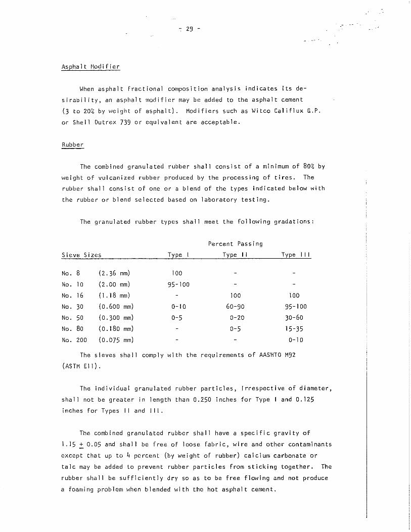
- 29 -
As pha It Mod i fie r
When asphalt fractional composition analysis indicates its de
sirability, an asphalt modifier may be added to the asphalt cement
(3 to 20;~ by weight of asphalt). Modifiers such as Witco Califlux G.P.
or She 11 Dutrex 739 0 r equ iva 1 en tare acceptab 1 e.
Rubber
The combined granulated rubber shall consist of a minimum of 80% by
weight of vulcanized rubber produced by the processing of tires. The
rubber shall consist of one or a blend of the types indicated below with
the rubber or blend selected based on laboratory testing.
The granulated rubber types shall meet the following gradations:
Sieve Sizes Type
Percent Passing
Type II Type III
No. 8 (2.36 mm) 100
No. 10 (2.00 mm) 95-100
No. 16 (1 . 18 mm) 100 100
No. 30 (0.600 mm) 0-10 60-90 95-100
No. 50 (0.300 mm) 0-5 0-20 30-60
No. 80 (0.180 mm) 0-5 15-35
No. 200 (0.075 mm) 0-10
The sieves shall comply with the requirements of AASHTO M92
(ASTM Ell).
The individual granulated rubber particles, irrespective of diameter,
shall not be greater in length than 0.250 inches for Type I and 0.125
inches for Types II and III.
The combined granulated rubber shall have a specific gravity of
1.15 ~ 0.05 and shall be free of loose fabric, wire and other contaminants
except that up to 4 percent (by weight of rubber) calcium carbonate or
talc may be added to prevent rubber particles from sticking together. The
rubber shall be sufficiently dry so as to be free flowing and not produce
a foaming problem when blended \;ith the hot asphalt cement.

- 30 -
The granulated rubber shall be accepted by certification from the
rubber suppl ier.
Diluent
The diluent shall have an initial boiling point (IBP) of 171°C when
tested in accordance \-1i th ASTM D-86.
Asphalt Rubber Mixing and Reaction
The percent of combined rubber shall be 23 ~ 3 percent by weight of
total mixture, that is, by total weight of asphalt cement + asphalt
modifier (if used) + granulated rubber.
The temperature of the asphalt shall be between (177 to 218°C) at
the addition of the vulcanized rubber. The asphalt and rubber shall be
combined and mixed togetJler in a blender unit and reacted in the distri
butor for a period of time as required by the Engineer \-Jhich shall be
based on laboratory testing by the asphalt-rubber supplier. The tempera
ture of the asphalt-rubber mixture shall be above (163°C) during the
reaction period.
After the reaction between asphalt and rubber has occurred, the
viscosity of the hot asphalt-rubber mixture may be adjusted for spraying
and/or better "v-Jetting" of the cover material by the addition of a
diluent. The diluent shall not exceed 7-1/2 percent by volume of the hot
asphalt-rubber mixture.
When a job delay occurs after full reaction, the asphalt-rubber may
be allowed to cool. The asphalt-rubber shall be reheated slowly just prior
to appl ication but not to a temperature exceeding (163°c). An additional
quantity of diluent not exceeding 3 percent by volume of the hot asphalt
rubber mixture may be added after reheating.
AGGREGATE
The stone chips shall comply with the requirements for coarse aggregate
for HL-3 as indicated in MTC Form 1003 - Material Specification for
Aggregates Hot Mix Asphaltic Concrete.
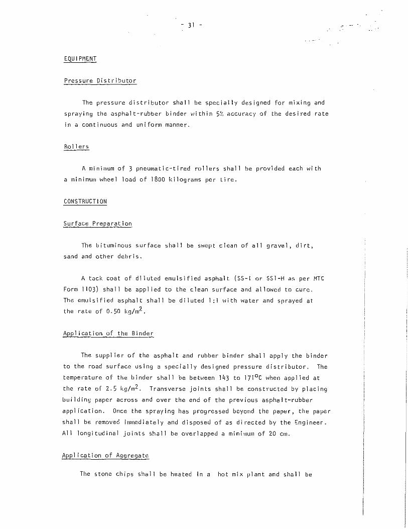
- 31 -
EQU I PMENT
Pressure Distributor
The pressure distributor shall be specially designed for mixing and
spraying the asphalt-rubber binder within 5% accuracy of the desired rate
in a continuous and uniform manner.
Rollers
A minimum of 3 pneumatic-tired rollers shall be provided each with
a minimum wheel load of 1800 kilograms per tire.
CONSTRUCTION
Surface Preparation
The bituminous surface shall be sVJept clean of all gravel, dirt,
sand and other debris.
A tack coat of diluted emulsified asphalt (SS-I or SSI-H as per MTC
Form 1103) shall be appl ied to the clean surface and allowed to cure.
The emulsified asphalt shall be diluted 1:1 "Iith water and sprayed at
the rate of 0.50 kg/m2 .
Appl ication of the Binder
The suppl ier of the asphal t and rubber binder shall apply the binder
to the road surface using a specially designed pressure distributor. The
temperature of the binder sha II be between 1~3 to 11IoC when app lied at
the rate of 2.5 kg/m2 . Transverse joints sha II be constructed by placing
building paper across and over the end of the previous asphalt-rubber
appl ication. Once the spraying has progressed beyond the paper, the paper
shall be removed immediately and disposed of as directed by the Engineer.
All longi tudinal joints shall be overlapped a minimum of 20 em.
Appl ieation of Aggregate
The stone chips shall be heated in a hot mix plant and shall be

- 32 -
applied immediately at a temperature of 121 to 1490 C, to the asphalt
rubber binder, at the rate of 16.5 kg/m2 .
Roll ing
Roll ing shall commence immediately behind the aggregate spreader,
and if the spreading is stopped for an extended period, the spreader shall
be moved ahead or off to the side so that all cover material may be
immediately rolled. Four complete passes wi th rollers shall be made wi th
all roll ing completed within 1/2 hour after the appl ication of the
cover material.
Rotary Power Brooming
When the aggregate is thoroughly embedded and rolling has been
completed, the surface shall be swept with power brooms to remove any
excess aggregate before opening the road to traffic.
Temperature and Weather
The work shall not be started unless the pavement is absolutely dry
and surface temperature is at least 16°c or when in the opinion of the
Engineer conditions are not conducive to successful results.
MEASUREMENT FOR PAYMENT
Supply and Application of Binder
The quantity of binder appl ied to the road will be measured in tonnes.
Supply and Application of Aggregate
The quantity of aggregate appl ied to the road "Jill be measured in
tonnes.

- 33 -
BAS I S OF PAYMENT
Supply and Application of Binder
Payment for this work will be made at the contract unit price per
tonne, and such payment will be full compensation for sweeping, applying
the tack coat, for supplying, mixing, heating and applying the binder to
the road surface as specified and for all other work necessary to
complete the appJ jeat.ion in accordance with this specification.
Supply and Appl ication of Aggregate
Payment for this work will be made at the contract unit price per
tonne and such payment will be full compensation for supplying, heating,
handling, hauling, spreading, rolling and brooming and for all other work
necessary to complete the appl ication in accordance with this specification.

APPEI,DIX C
Binder Viscosi ty
- 34 -
The viscosity of the rubber asphalt binder was checked on site by
Sahuaro wi th a small hand held instrument, the Haake Viscotester. A one
gallon paj I of binder was taken from the distributor, the temperature
checked and the viscosity measured. A rod hanging beneath the viscotester
was immersed into the binder and the force required to turn the rod was
read from the scale. The asphalt/rubber reaction was complete when the
binder reached 7000-9000 centipoises. Kerosene was added reducing the
viscosi ty to 4000-5000 centipoises and the rubber asphalt binder was
ready to sp ray.

- 35 -
'-----_.
/
L
Figure 22: Checking Temperature of RubberAsphalt Binder Prior to App1 ication
Figure 23: Checking Viscosity of RubberAsphal t Binder With Haake Viscotester
Figure 2~: Trays for Checking AppJ ication Rates

- 36 -
P,PPEIID I X D - FIE LD SAI1PL lUG TO DETERH 11,[ TH£: AI',QUIH OF B IlmER AHD AGGREGATE APPLIED TO A ROAD
The following equipment is required:
(I) I - Battery operated digital scale, 10 kg capacity, >Iith a stainless steel platform approximately 30 em x 40 cm.
(2) A supply of cardboard trays 50 em x 50 em with a 2.S·cm lip.
(3) Pocket calculator.
(4) Carpenter's level.
(S) Gloves.
(6) Mineral spirits.
(71 Rags.
Procedure
(I) Set up and level digital scales.
(2) Number the cardboard trays.
(3) Obtain the tare weight in ki lograms of two 50 x. 50 em car'dboard trays and record.
(4) Place the two cardboard trays in the centre of the lane being treated approximately two feet apart and parallel to the centreline of the road, immediately prior to the area being treated.
(S) Remove the first tray after the binder has been sprayed and before the aggregate has been appl ied.
(6) Remove the second tray after the binder has been sprayed and the aggregate has been appl ied and before roll ing.
(71 Obtain the gross weight in kilograms of the first tray.
(8) Obtain the net weight in kilograms of binder appl ied in the first tray. Net Weight = Gross Weight - Tare Weight.
(9) Calculate the amount of binder appl ied to the road as follmls:
Net Weight (8) x 4 =

- 37 -
(10) Obtain the gross \.\'eight in kilograrr,5 of the secc.nd tray.
(II) Obtain the net weight in kilograrr,s of binder and aggregate appl ied in the second tray.
Net Weight ~ Gross Weight - Tare Weight
(12) Obtain the net "eight in kilograms of aggregate applied in the second tray.
Net weight of aggregate ~ net weight of second tray (II)
- net weight of first tray (8)
(13) Calculate the amount of aggregate appl ied to the road as fo Ilovls:
Net weight of aggregate (12) x 4 kg/m2
(14) Repeat sampl ing process at least three times per 2.0 kin lanes and adjust appl ieatien rates if necessary to obtained desired quantities.
Maintenance
recharge the batteries in the scale as required.
cle~n scale platform with mineral spirits and rags after use.

- 38 -
Figure 25: Trays Removed After Appl ication of SAMI
Figure 26: Portable Digital Scales to Weigh Trays
Figure 27: Weighing Tray of Rubber Asphal t Binder