střešní hydroizolační systém - fatrafol.cz · substance content in accordance with (under)...
TRANSCRIPT

Roof waterproofing system
FATRAFOL-S
CONSTRUCTION AND TECHNOLOGICAL INSTRUCTIONS
for installation of waterproofing membranes
on roof decks

Page 2 FATRAFOL-S Roof waterproofing system
08/2017
PN 5415/2011 FATRAFOL-S Title: Construction and technological Instructions for installation of FATRAFOL waterproofing membranes
on roof decks
Prepared by: Studio of insulations
Issued by: FATRA, a.s., Tomase Bati 1541, 763 61 Napajedla, Czech Republic
Version: 07/2018
Effective date: 01-07-2018

Roof waterproofing system FATRAFOL-S Page 3
08/2017
CONTENT:
1 APPLICATION AND FEATURES OF FATRAFOL-S ROOF WATERPROOFING SYSTEM ...................................... 8
1.1 SCOPE OF APPLICATION ........................................................................................................................................................ 8 1.2 ROOF CLASSIFICATION BY WATERPROOFING MEMBRANE LOCATION AND FASTENING METHOD ............................................. 9 1.3 TYPICAL END-USE PROPERTIES OF FATRAFOL-S ROOF COVERING SYSTEM ........................................................................ 9 1.4 WARRANTIES ................................................................................................................................................................. 10
2 FATRAFOL-S WATERPROOFING SYSTEM MATERIALS .......................................................................................... 11
2.1 FATRAFOL WATERPROOFING MEMBRANES ...................................................................................................................... 11 2.1.1 Membrane manufacture and basic product classification ......................................................................................... 12 2.1.2 Temperature resistance and welding temperatures ................................................................................................... 12 2.1.3 Chemical resistance ................................................................................................................................................... 12 2.1.4 Strength characteristics ............................................................................................................................................. 14 2.1.5 Packaging, transport and storage ............................................................................................................................. 14 2.1.6 Membrane labelling and identification ..................................................................................................................... 14 2.1.7 Safety regulations ...................................................................................................................................................... 15 2.1.8 Legislative requirements............................................................................................................................................ 16 2.1.9 Description and technical specifications of waterproofing membrane types ............................................................ 18
2.1.9.1 PVC-P waterproofing membranes ............................................................................................................................................ 18 2.1.9.1.1 FATRAFOL 807 waterproofing membrane ........................................................................................................................ 18 2.1.9.1.2 FATRAFOL 807/V waterproofing membrane .................................................................................................................... 20 2.1.9.1.3 FATRAFOL 810 (810/V) waterproofing membranes ......................................................................................................... 22 2.1.9.1.4 FATRAFOL 814 waterproofing membrane ........................................................................................................................ 28 2.1.9.1.5 FATRAFOL 818/V-UV waterproofing membrane ............................................................................................................. 30 2.1.9.1.6 FATRAFOL 804 waterproofing membrane ........................................................................................................................ 32
2.1.9.2 FPO waterproofing membranes ................................................................................................................................................ 34 2.1.9.2.1 FATRAFOL P 916 waterproofing membrane ..................................................................................................................... 34 2.1.9.2.2 FATRAFOL P 918 waterproofing membrane ..................................................................................................................... 36 2.1.9.2.3 FATRAFOL P 918/SG waterproofing membrane ............................................................................................................... 38 2.1.9.2.4 FATRAFOL P 918/H waterproofing membrane ................................................................................................................. 40
2.2 SUPPLEMENTARY WATERPROOFING MATERIALS ................................................................................................................. 42 2.2.1 Accessories for PVC-P membranes ........................................................................................................................... 42
2.2.1.1 Shaped piece – internal corner .................................................................................................................................................. 42 2.2.1.2 Shaped piece – external corner ................................................................................................................................................. 42 2.2.1.3 Vent outlets ............................................................................................................................................................................... 42 2.2.1.4 Cable outlet flashing ................................................................................................................................................................. 43 2.2.1.5 Rainwater outlets ...................................................................................................................................................................... 43 2.2.1.6 Rainwater outlets for existing roof downpipes .......................................................................................................................... 44 2.2.1.7 Spouts and overflow outlets ...................................................................................................................................................... 44 2.2.1.8 Shaped sleeves .......................................................................................................................................................................... 44 2.2.1.9 ‘A’ profile Novoplast 1871 ....................................................................................................................................................... 44 2.2.1.10 Plastic-coated installation components ................................................................................................................................. 45 2.2.1.11 Flat component - patch ......................................................................................................................................................... 45 2.2.1.12 Flat component – collar ........................................................................................................................................................ 45 2.2.1.13 Extrusion PVC wire .............................................................................................................................................................. 45 2.2.1.14 Z-01 sealant .......................................................................................................................................................................... 46 2.2.1.15 L-494 diluent ........................................................................................................................................................................ 46 2.2.1.16 PVC P membrane TW Cleaner ............................................................................................................................................. 46 2.2.1.17 Polyurethane sealer ............................................................................................................................................................... 46 2.2.1.18 Polymer sealer ...................................................................................................................................................................... 47 2.2.1.19 Liquid waterproofing products ............................................................................................................................................. 47
2.2.1.19.1 Triflex ProDetail ............................................................................................................................................................... 47 2.2.1.19.2 Triflex ProFibre ................................................................................................................................................................. 48
2.2.1.20 FATRANYL – L plastic-coated metal profiles ..................................................................................................................... 49 2.2.2 Accessories for FPO membranes............................................................................................................................... 52
2.2.2.1 Shaped piece – internal corner .................................................................................................................................................. 52 2.2.2.2 Shaped piece – external corner ................................................................................................................................................. 52 2.2.2.3 Vent outlets ............................................................................................................................................................................... 53 2.2.2.4 Cable outlet flashing ................................................................................................................................................................. 53
Page 4 FATRAFOL-S Roof waterproofing system
08/2017
2.2.2.5 Rainwater outlets ....................................................................................................................................................................... 53 2.2.2.6 Spouts and overflow outlets ...................................................................................................................................................... 53 2.2.2.7 Penetration components ............................................................................................................................................................ 53 2.2.2.8 FPO plastic-coated metal profiles FATRANYL-P .................................................................................................................... 54
2.3 AUXILIARY MATERIALS .............................................................................................................................................. 54 2.3.1 Vapour barriers .......................................................................................................................................................... 55
2.3.1.1 PE vapour control barrier .......................................................................................................................................................... 55 2.3.1.2 Bituminous vapour control barrier ............................................................................................................................................ 55
2.3.2 Thermal insulation ..................................................................................................................................................... 56 2.3.2.1 Mineral wool thermal insulation ............................................................................................................................................... 56 2.3.2.2 Expanded polystyrene foam (EPS) ............................................................................................................................................ 57 2.3.2.3 Extruded polystyrene foam (XPS) ............................................................................................................................................. 58 2.3.2.4 Polyisocyanurate (PIR) insulation boards ................................................................................................................................. 58
2.3.3 Separation and protective textile layers ..................................................................................................................... 59 2.3.3.1 Nonwoven separation textile ..................................................................................................................................................... 59 2.3.3.2 Glass fibre fleece ....................................................................................................................................................................... 59
2.3.4 Mechanical fasteners for waterproofing membranes ................................................................................................. 60 2.3.5 Adhesives .................................................................................................................................................................... 62
2.3.5.1 Polyurethane expansive adhesives for adhered system .............................................................................................................. 62 2.3.5.1.1 FATRAFIX TI ..................................................................................................................................................................... 62 2.3.5.1.2 FATRAFIX FM ................................................................................................................................................................... 63
2.3.5.2 Solvent-based contact adhesives ............................................................................................................................................... 63 2.3.5.2.1 FATRAFIX PVC ................................................................................................................................................................. 63 2.3.5.2.2 FATRAFIX FPO ................................................................................................................................................................. 64
2.3.5.3 FATRAFIX cleaners ................................................................................................................................................................. 65 2.3.5.3.1 FATRAFIX AC cleaner ....................................................................................................................................................... 65
2.3.6 Drainage layer ........................................................................................................................................................... 65 2.3.6.1 Drainage and water retention membranes ................................................................................................................................. 65 2.3.6.2 Petexdren drainage membrane .................................................................................................................................................. 66
2.3.7 Other .......................................................................................................................................................................... 66 2.3.7.1 MIRELON sealing cord ............................................................................................................................................................ 66 2.3.7.2 Shingle flashing ......................................................................................................................................................................... 66 2.3.7.3 Lightning rod holders ................................................................................................................................................................ 67 2.3.7.4 Snow guard ............................................................................................................................................................................... 67 2.3.7.6 Fall protection system ............................................................................................................................................................... 67 2.3.7.7 Butyl-rubber tape ...................................................................................................................................................................... 68 2.3.7.8 Levelling compound for flat roofs ............................................................................................................................................. 68
3 BASIC CONSTRUCTION PRINCIPLES ............................................................................................................................. 69
3.1 GENERAL ROOF DESIGN REQUIREMENTS ............................................................................................................................. 69 3.2 SUBSTRATE STRUCTURE ...................................................................................................................................................... 70
3.2.1 Requirements for substrate of new roof decks ............................................................................................................ 70 3.2.2 Requirements for substrate of refurbished roofs ........................................................................................................ 71 3.2.3 Substructure requirements for mechanical fastening ................................................................................................. 71
3.2.3.1 Fasteners for trapezoidal steel sheet metal ................................................................................................................................ 71 3.2.3.2 Fasteners for concrete and reinforced concrete ......................................................................................................................... 72 3.2.3.3 Fasteners for thin concrete prefabricates ................................................................................................................................... 72 3.2.3.4 Fasteners for porous concrete .................................................................................................................................................... 73 3.2.3.5 Fasteners for wooden substrates ................................................................................................................................................ 73 3.2.3.6 Problematic substrates ............................................................................................................................................................... 74
3.3 VAPOUR CONTROL LAYER ................................................................................................................................................... 74 3.4 THERMAL INSULATION ........................................................................................................................................................ 75 3.5 SEPARATION LAYER ............................................................................................................................................................ 76 3.6 MAIN WATERPROOFING LAYER ........................................................................................................................................... 76
3.6.1 Choosing a suitable membrane type for the main waterproofing layer ..................................................................... 77 3.6.2 Securing waterproofing membranes .......................................................................................................................... 78
3.6.2.1 Protecting membranes from internal forces ............................................................................................................................... 78 3.6.2.2 Fastening of internal corner flashing ......................................................................................................................................... 79 3.6.2.3 Securing the roof covering against external forces .................................................................................................................... 79
3.6.2.3.1 Mechanical fastening of the water-proofing cover .............................................................................................................. 80 3.6.2.3.2 Calculation of wind load and mechanical anchoring proposal ............................................................................................ 81 3.6.2.3.3 Empiric definition of anchoring density .............................................................................................................................. 82 3.6.2.3.4 Securing membranes with aggregate, traffic layer or a green layer...................................................................................... 85

Roof waterproofing system FATRAFOL-S Page 5
08/2017
3.6.2.3.5 Securing membranes with adhesives ................................................................................................................................... 87 3.6.3 Joining waterproofing membranes ............................................................................................................................ 88 3.6.4 Ending a roof covering at the roof perimeter ............................................................................................................ 89 3.6.5 Additional sealing of details ...................................................................................................................................... 90 3.6.6 Roof drainage ............................................................................................................................................................ 90
3.6.6.1 Linear drainage from roof ......................................................................................................................................................... 90 3.6.6.2 Point drainage from roof ........................................................................................................................................................... 91
3.7 TRAFFIC LAYER .................................................................................................................................................................. 92
4 TECHNICAL PREPARATION FOR INSTALLATION .................................................................................................... 93
4.1 DOCUMENTATION FOR INSTALLATION PREPARATION .......................................................................................................... 93 4.2 GETTING READY FOR INSTALLATION ................................................................................................................................... 93
5 TECHNOLOGICAL PROCEDURES ................................................................................................................................... 95
5.1 EXTERNAL CONDITIONS FOR WATERPROOFING WORKS ................................................................................... 95 5.1.1 Site readiness ............................................................................................................................................................. 95 5.1.2 Working conditions .................................................................................................................................................... 96
5.2 INSTALLING A ROOF COVERING ........................................................................................................................................... 96 5.2.1 Installing a vapour control layer ............................................................................................................................... 97 5.2.2 Installing a thermal insulation layer ......................................................................................................................... 97 5.2.3 Installing a base, protective and separation layer .................................................................................................... 98 5.2.4 Installing perimeter profiles ...................................................................................................................................... 98 5.2.5 Installing a waterproofing membrane ....................................................................................................................... 99
5.2.5.1 FATRAFOL 810 and 810/V (mechanically fastened covering) ................................................................................................ 99 5.2.5.1.1 Fastening a membrane at its perimeter .............................................................................................................................. 102 5.2.5.1.2 Point-fastening a membrane in sheet area ......................................................................................................................... 102
5.2.5.2 FATRAFOL 807 and 807/V membranes (bonded covering) .................................................................................................. 103 5.2.5.3 FATRAFOL 818/V-UV membranes (ballasted roof) .............................................................................................................. 105 5.2.5.4 FATRAFOL 814 membrane (pedestrian traffic covering) ...................................................................................................... 106 5.2.5.5 FATRAFOL P 916 and 918 SG membranes (mechanically fastened covering) ..................................................................... 108 5.2.5.6 FATRAFOL P 918 membrane (loaded covering) ................................................................................................................... 108
5.2.6 Roof detailing .......................................................................................................................................................... 108 5.2.6.1 Ending waterproofing membranes on vertical structures ........................................................................................................ 108 5.2.6.2 Parapet detailing ..................................................................................................................................................................... 109
5.2.6.2.1 Ending a parapet with plastic-coated metal profiles .......................................................................................................... 109 5.2.6.2.2 Ending membranes under parapet flashing ........................................................................................................................ 109
5.2.6.3 Ending membrane at roof plane .............................................................................................................................................. 110 5.2.6.3.1 Ending membranes at roof plane with drip mould of plastic-coated sheet metal .............................................................. 110 5.2.6.3.2 Ending membranes at roof plane with gravel stop............................................................................................................. 110
5.2.6.4 Valley and parapet gutters, recessed valleys ........................................................................................................................... 111 5.2.6.5 Rainwater outlets .................................................................................................................................................................... 111 5.2.6.6 Pipe penetrations ..................................................................................................................................................................... 112
5.2.6.6.1 PVC or FPO circular pipe penetrations ............................................................................................................................. 112 5.2.6.6.2 Non-circular penetrations .................................................................................................................................................. 113
5.2.6.7 Installing vent outlets .............................................................................................................................................................. 114 5.2.6.8 Dividing roof area with Novoplast profile .............................................................................................................................. 115 5.2.6.9 Expansion joints ...................................................................................................................................................................... 115
5.2.7 Protecting the roof surface from mechanical damage ............................................................................................ 115 5.2.8 Installing top separation layer ................................................................................................................................ 116 5.2.9 Installing loading layer on roof covering ................................................................................................................ 116 5.2.10 Repairing damaged roof covering ........................................................................................................................... 117
6 OCCUPATIONAL HEALTH & SAFETY, FIRE PREVENTION ................................................................................... 118
6.1 OCCUPATIONAL HEALTH & SAFETY AT CONSTRUCTION SITE ............................................................................................ 118 6.2 FIRE PREVENTION ............................................................................................................................................................. 118 6.3 INSTALLATION-RELATED SAFETY RISKS ............................................................................................................................ 118 6.4 ROOF SAFETY DURING USE ............................................................................................................................................... 121
7 INSPECTIONS AND ACCEPTANCE OF INSTALLED FATRAFOL-S SYSTEM ...................................................... 122
7.1 QUALITY INSPECTION ....................................................................................................................................................... 122 7.2 TIGHTNESS TESTS ............................................................................................................................................................. 123

Page 6 FATRAFOL-S Roof waterproofing system
08/2017
8 FITTER’S QUALIFICATIONS AND EQUIPMENT ........................................................................................................ 125
8.1 QUALIFICATIONS ............................................................................................................................................................... 125 8.2 FITTERS’ EQUIPMENT ........................................................................................................................................................ 125
8.2.1 Electrical equipment ................................................................................................................................................ 125 8.2.2 Work tools ................................................................................................................................................................ 126 8.2.3 Essential hand tools – installation kit ...................................................................................................................... 127
9 NORMATIVE REFERENCES ............................................................................................................................................. 128
10 TYPICAL ROOFING DETAILS ..................................................................................................................................... 129
10.1 OVERVIEW OF DETAILS ..................................................................................................................................................... 129 10.1.1 Joining FATRAFOL- mutually and with supplementary materials .......................................................................... 129 10.1.2 Ending roof covering on vertical surface ................................................................................................................. 129 10.1.3 Transition of roofing membrane from vertical to horizontal position ...................................................................... 129 10.1.4 Detailing of parapets and ending of roof covering at roof plane ............................................................................ 130 10.1.5 Gutters, rainwater outlets and penetrations ............................................................................................................. 130 10.1.6 Expansion joints ....................................................................................................................................................... 130
10.2 DRAWINGS OF DETAILS ..................................................................................................................................................... 131

Roof waterproofing system FATRAFOL-S Page 7
08/2017
INTRODUCTION
This Instructions must be followed when designing and installing FATRAFOL roof waterproofing membranes in new buildings and reconstructed roofs, and when refurbishing existing roof decks. The membranes are based on plasticised polyvinyl chloride (PVC-P) and flexible polyolefin (FPO), and manufactured by FATRA, a.s. Napajedla.
The Instructions summarises theoretical and practical knowledge and expertise acquired through research, testing, design and installation of roof waterproofing membranes since 1982. The Instructions constitutes an integral part of the FATRAFOL-S roof waterproofing system. Any modifications to or deviations from the criteria, requirements and rules contained herein, whether on economic, performance or operational grounds, are only allowed with FATRA’s prior review and approval.
This issue of the construction and technological Instructions supersedes its previous version.
For any enquiries, please contact:
FATRA, a.s. Třída Tomáše Bati 1451 763 61 Napajedla Czech Republic
Tel.: 577 503 323 Fax: 577 502 650 Email: [email protected] Internet: http//www.fatra.cz http//www.fatrafol.cz

Page 8 FATRAFOL-S Roof waterproofing system
08/2017
1 APPLICATION AND FEATURES OF FATRAFOL-S ROOF WATERPROOFING
SYSTEM
1.1 Scope of application
The FATRAFOL-S waterproofing system is designed to create membrane roof coverings for all types of residential, public, administrative, industrial, agricultural, sports and similar buildings with a flat or pitched roof. The system is suitable for all roof designs, i.e. single-, two- and multi-ply roofs, ventilated and non-ventilated roofs, roofs with the standard arrangement of a thermal insulation layer, inverted or combined roofs, flat, pitched and steep roofs, roofs open or closed to pedestrian traffic, vehicular traffic roofs, roofs with aggregate or soil, green roofs and roof gardens, photovoltaic roofs etc.
Subject to compliance with the instructions below, FATRAFOL-S roofing membranes may be laid on all conventional substrates (concrete, concrete prefabricated components, lightweight concrete, wood, polystyrene foam, polyurethane, polyisocyanurate, mineral fibre boards, asphalt covering etc), both in new buildings and in renovated, reconstructed and refurbished old buildings.
Highly versatile, the FATRAFOL-S system suits a wide range of applications.

Roof waterproofing system FATRAFOL-S Page 9
08/2017
1.2 Roof classification by waterproofing membrane location and fastening method
Depending on the waterproofing membrane location and attachment to the roof deck, the FATRAFOL-S roof waterproofing system is divided into four distinctive subsystems:
Mechanically fastened waterproofing membranes FATRAFOL membrane is fastened mechanically to the substrate Typical for lightweight roof structures
Adhered waterproofing membranes FATRAFOL membrane is adhered to a suitable substrate Usable for almost all structures, pitches and shapes
Waterproofing membranes ballasted by pea gravel or traffic layer Only for roofs with static capacity able to support extra load FATRAFOL membrane is protected from direct weather conditions and secured against wind loads Ballast provides protection from external fire The system requires only minimum maintenance
1.3 Typical end-use properties of FATRAFOL-S roof covering system
The roof covering typically includes a single membrane layer with a waterproofing layer thickness of 1.5 mm.
The roof covering weight on the roof structure does not exceed 3.2 kg.m-2
.
All joints within the roof covering are made of high-strength and watertight welds and may be additionally secured.
The roof covering offers long-term resistance to weather-caused corrosion including UV radiation.
The roof covering is highly resistant to aggressive chemicals in the air, industrial pollution, extracts from concrete and a number of other substances.
The roof covering features great strength, elongation at break and elasticity and maintains its end-use properties at temperatures between -30°C and +80°C.
The roof covering meets building fire safety requirements as prescribed by Czech and European standards.
A good degree of waterproofing membrane permeability for water vapours allows continuous moisture diffusion from the roof deck into the atmosphere.
The roof covering surface provides good reflection and minimum absorption of solar heat radiation.
Based on existing long-term practical experience and laboratory tests, the roof covering offers at least 25 years of service life.
The roof covering is fully compatible with all accessories and auxiliary items within the FATRAFOL-S system.

Page 10 FATRAFOL-S Roof waterproofing system
08/2017
Works can be carried out throughout the year, except rain, snow and temperatures below -5°C (below -10°C in case of FPO membranes). The roof covering may also be installed on a damp substrate.
The roof covering is maintenance free throughout its service life except for regular recommended inspections of selected structures.
If damaged, the roof covering is easy to repair.
Easy renovation or removal of roof covering if required
1.4 WARRANTIES
In addition to statutory warranties Fatra, a.s. provides extended warranty on waterproofing membrane in system FATRAFOL-S. Condition for warranties on material are described on website www.fatrafol.cz. Basic warranty on waterproofing membranes FATRAFOL is 10 years starting from day of application, but no more than 11 years since day of first sale.
Warranties on damaged material or material with uncertain technical condition must be claimed before its installation. Origin of material must be proven by its label.
Warranty cannot be claimed on material colour stability, damaged surface gloss, pollution of membrane surface or pollution of membrane caused by external environment and on membrane changes caused by inappropriate use or maintenance.

Roof waterproofing system FATRAFOL-S Page 11
08/2017
2 FATRAFOL-S WATERPROOFING SYSTEM MATERIALS
The materials comprising the FATRAFOL-S system are divided as follows:
FATRAFOL waterproofing membranes
Supplementary waterproofing materials
Auxiliary materials
The materials mentioned below are made by Fatra, a.s. and by other suppliers. When installing the FATRAFOL-S system, specified waterproofing materials must be considered non-interchangeable. Author does not take any responsibility for design and installation of waterproofing construction if it isn’t in comply with these Instructions.
2.1 FATRAFOL waterproofing membranes
FATRAFOL waterproofing membranes are the key material of the main waterproofing layer.

Page 12 FATRAFOL-S Roof waterproofing system
08/2017
2.1.1 Membrane manufacture and basic product classification
FATRAFOL membranes are manufactured only from raw materials of exactly defined properties. The composition and design of individual membrane types are such to give the membranes optimal technical parameters for their intended use.
Classification of FATRAFOL membranes by basic criteria:
a) By the manufacturing technology:
Calendered and laminated
Manufactured by the process of multiple extrusion
b) By the material base:
Membranes from plasticised polyvinyl chloride (PVC-P)
Membranes from flexible polyolefins (FPO)
c) By intended use:
Basic types (membranes for the main waterproofing layer)
Additional types (for detailing as an accessory to basic membrane types)
Table 1 shows a detailed classification of the membrane range.
Table 1: FATRAFOL range classification
Reinforcement type PVC-P membranes
FPO membranes Laminated Extruded
Basic types of waterproofing membranes
High-strength PES grid FATRAFOL 810 FATRAFOL 810/V FATRAFOL P 916
Glass fibre fleece FATRAFOL 814 FATRAFOL 818/V-UV FATRAFOL P 918
Base non-woven fleece FATRAFOL 807 FATRAFOL 807/V -
Combined reinforcement - - FATRAFOL P 918/SG
Additional types of waterproofing membranes
Without reinforcement fleece FATRAFOL 804 - FATRAFOL P 918/H
2.1.2 Temperature resistance and welding temperatures
FATRAFOL roofing membranes offer long-term resistance to most types of corrosive loads including thermal loads. Their key performance properties remain basically stable at temperatures between -30°C and +80°C and the membranes can be installed at temperatures between -5°C (-10°C in case of FPO membranes) and +40°C. The membranes also withstand very sudden and recurring temperature changes without damage, even offer short-term resistance to extreme overheating *).
Recommended welding temperatures are 430°C up to 600°C for PVC-P based membranes and 450°C up to 550°C for FPO based membranes. The welding temperature depends on numerous factors such as membrane thickness and type, welding machine type, welding speed, substrate and ambient air temperature and humidity, wind speed etc. An on-site test must be performed to set the correct welding temperature. The manufacturer recommends making test welds with various welding machine settings before the start of work and adjusting the parameters to tensile test results.
*) Note: Even brief exposure of FPO membranes to extreme overheating may cause thermal decomposition of polymer and have a negative impact on the quality of joints.
2.1.3 Chemical resistance
With their excellent chemical resistance, FATRAFOL membranes may be used in environments with high chemical exposure. For a basic overview of chemical resistance at a standard temperature of 23°C, see Table 2 for PVC-P membranes and Table 3 for FPO membranes respectively. As chemical resistance depends largely on concentration and temperature of the substance and on exposure time, every case must be treated individually and a separate assessment must be made, in particular, of any substances not listed below and their combinations with respect to their estimated impact on the membrane.

Roof waterproofing system FATRAFOL-S Page 13
08/2017
Table 2: Chemical resistance of FATRAFOL PVC-P membranes
Inorganic acids Salt solutions
Sulphuric acid 25% + Sulphates +
Sulphuric acid 98% ∆ Chlorides +
Sulphurous acid 6% + Nitrates +
Nitric acid 5% + Organic substances
Hydrochloric acid 10% + Acetone –
Concentrated hydrochloric acid ∆ Ethyl alcohol 10% +
Organic acids Ethylene glycol ∆
Benzoic acid + Petrol –
Butyric acid ∆ Diesel –
Acetic acid 10% + Plant and animal oils ∆
Citric acid + Motor and mineral oils ∆
Tartaric acid + Tar –
Oxalic acid + Toluene –
Oleic acid ∆ Other
Inorganic bases Asphalt –
Sodium hydroxide + Beer +
Potassium hydroxide + Soap solutions +
Ammonium hydroxide + Sea water +
Calcium hydroxide + Washing agents +
Herbicides +
Fertilisers +
Chemical resistance rating: + long-term resistance ∆ limited resistance - not resistant
Table 3: Chemical resistance of FATRAFOL FPO membranes
Inorganic acids Salt solutions
Sulphuric acid 25% + Sulphates +
Sulphuric acid 98% ∆ Chlorides +
Sulphurous acid 6% + Nitrates +
Nitric acid 5% + Organic substances
Hydrochloric acid 10% + Acetone ∆
Concentrated hydrochloric acid ∆ Ethyl alcohol 10% +
Organic acids Ethylene glycol +
Benzoic acid + Petrol –
Butyric acid + Diesel ∆
Acetic acid 10% + Plant and animal oils ∆
Citric acid + Motor and mineral oils ∆
Tartaric acid + Tar ∆
Oxalic acid + Toluene –
Oleic acid ∆ Other
Inorganic bases Asphalt +
Sodium hydroxide + Beer +
Potassium hydroxide + Soap solutions +
Ammonium hydroxide + Sea water +
Calcium hydroxide + Washing agents +
Herbicides +
Fertilisers +
Chemical resistance rating: + long-term resistance ∆ limited resistance - not resistant

Page 14 FATRAFOL-S Roof waterproofing system
08/2017
2.1.4 Strength characteristics
FATRAFOL’s mechanical properties include great tensile and compression strength and high elongation at break. Deformations of PVC-P membranes are largely reversible (elastic). FATRAFOL membranes also provide very good resistance to point stress (punctures, tears etc) and do not develop the so-called ‘cold flow’ when exposed to stress.
Some membrane types are reinforced with a high-strength fleece grid for added strength.
2.1.5 Packaging, transport and storage
Membranes are wound into rolls and wrapped; the rolls are placed on wooden pallets and secured in place with wrap film. See Figure 1 for basic packaging arrangements.
Typically, a pallet holds 19 rolls of 1,300 (1,200) mm wide membranes and 21 rolls of 2,000 (2,050) mm wide membranes.
Non-standard pallets hold 18 rolls of 2,000 (2,050) mm wide membranes, with the rolls having reduced length and weight and being block-stacked in 3 layers.
19 and 21 rolls on pallet 21 rolls on pallet 18 rolls on pallet
Pallet 800x1,200 mm Pallet 800x1,200 mm Pallet 1,200x2,000 mm Pallet 800x2,000 mm Pallet 800x2,000 mm (shorter membrane length)
Figure 1: Handling and transport units – roll arrangement on pallet
Membranes must be transported in covered vehicles and stored in original closed packaging.
Membranes should be stored at between -5°C and +30°C. Membranes must be protected from dirt at the construction site. If possible, membranes should be protected from the weather until installed.
2.1.6 Membrane labelling and identification
Identification details are ink-printed on the top surface of FATRAFOL membranes, usually 120 mm from their edge, indicating membrane dimensions (width, thickness) in mm, date of manufacture and identification data. In addition, a ‘+’ symbol is ink-printed at 150 mm intervals along the entire membrane length to allow easy adjustment of overlaps.
Each roll carries a label with a CE conformity mark. A unique production lot and production code are used for material identification in the manufacturing plant.

Roof waterproofing system FATRAFOL-S Page 15
08/2017
06
Fatra, a. s., třída Tomáše Bati 1541, 763 61 Napajedla, Czech Republic
DoP No. 5100806004
Název výrobku – Trade name FATRAFOL 810/V
Rozměr – Size 1,50 mm 2 050 mm
Množství – Quantity 20 m 41 m2
Barva – Colour RAL 7040 Použití: Mechanicky kotvená hydroizolační vrstva
Reakce na oheň: třída E
Chování při vnějším požáru: BROOF (t1), BROOF (t2), BROOF (t3)
Nejvyšší tahová síla P/N: ≥ 1000/1100 N/50 mm
Protažení při nejvyšší tahové síle P/N: ≥ 15/20 %
Odolnost proti statickému zatížení: vyhovuje 20 kg
Vodotěsnost 400 kPa: vyhovuje
Odolnost proti nárazu, metoda A: vyhovuje 1250 mm, metoda B:
vyhovuje 2000 mm
Odolnost proti protrhávání P/N: ≥ 200/220 N
Odolnost proti odlupování ve spoji P/N: ≥ 260/260 N/50 mm
Odolnost spoje ve smyku P/N: ≥ 1000/1000 N/50 mm
Ohebnost za nízkých teplot: ≤ -25 °C
Vystavení UV záření, zvýšené teplotě a vodě: vyhovuje, stupeň 0
Exposed application: Mechanically fastened roofing
Reaction to fire: Class E
External fire performance: BROOF (t1), BROOF (t2), BROOF (t3)
Maximum tensile force MD/CD: ≥ 1000/1100 N/50 mm
Elongation at maximum tensile force MD/CD: ≥ 15/20 %
Resistance to static loading: pass 20 kg
Watertightness 400 kPa: pass
Resistance to impact, method A: pass 1250 mm, method B: pass 2000 mm
Tear resistance MD/CD: ≥ 200/220 N
Joint peel resistance MD/CD: ≥ 260/260 N/50 mm
Joint shear resistance MD/CD: ≥ 1000/1000 N/50 mm
Foldability at low temperature: ≤ -25 °C
Exposure to UV radiation, elevated temperature and water: pass, grade 0
Certificate No 02/3921
1020
Fatra, a. s., třída Tomáše Bati 1541, 763 61 Napajedla, Czech Republic
12
1020-CPD-010030321
ETA-12/0013
Systémy mechanicky kotvených pružných střešních hydroizolačních povlaků
Systems of mechanically fastened flexible roof waterproofing membranes
ETAG 006
Výrobní dávka:
Batch production: F1416 Výrobní kód:
Production code: ML-N
2.1.7 Safety regulations
Occupational health and safety
FATRAFOL membranes are meant only for professional use
According to article 3.3 of Regulation (EC) No. 1907/2006 (hereafter referred to as REACH) waterproofing membrane
FATRAFOL is an object and therefore there is no obligation to provide a Safety Data Sheet for this product in the
sense of article 31 of REACH. According to the Regulation (EC) No.1272/2008 (= CLP) product is not classified as dangerous.
When in prolonged contact with the skin it is recommended to wear protective gloves for FATRAFOL membranes treated with biocidal product as described in Safety Instructions within the meaning of Article 58.4 of Regulation (EU) No. 528/2012 (= BIOCIDE),
Some FATRAFOL membranes contain substance listed in Annex XIV of REACH. Mandatory information about the substance content in accordance with (under) Article 33 is described in invoice (bill of sale). Safety instructions are provided upon the customer request.
It is necessary to follow all current safety, hygienic and fire regulations when installing and joining
Page 16 FATRAFOL-S Roof waterproofing system
08/2017
Waste disposal
FATRAFOL membrane waste can be recycled. Waste unsuitable for recycle can be stored in landfills. Waste contaminated by dangerous substances must be incinerated (disposed of) in hazardous waste incinerator.
FATRAFOL membrane waste meeting increased fire resistance request (indicated as T3) contain substance exceeding concentration limit 1% specified in table 6, Commission Regulation (EC) No 1357/2014.
FATRAFOL membrane waste containing substance listed in Annex XIV of REACH exceeds the concentration limit 0,3% specified in table 7, Commission Regulation (EC) No 1357/2014.
Waste must be handled in compliance with the local valid legal regulations governing the disposal of waste as well as with other local environmental regulations.
Table 4: Categorization and FATRAFOL membrane waste recovery
Catalog
number
Waste name according
to catalog number
Waste characteristic,
note Waste disposal or recovery operations
07 02 13 Plastic waste PVC-P membrane - material recovery
a), c), d)
- waste disposal (hazardous waste incineration b)
, landfill
a))
07 02 13 Plastic waste FPO membrane
- material recovery a)
- energy recovery
a)
- waste disposal (hazardous waste incineration b)
, landfill
a)
15 01 01 Paper and cardboard packaging
paper tubes - material recovery
15 01 02 Paper and cardboard packaging
PE membrane
covering and PE
stretch membrane
- material recovery
a) Waste b) Waste contaminated by dangerous substances c) FATRAFOL membrane waste meeting increased fire resistance request (indicated as T3) contain substance
exceeding concentration limit 1% specified in table 6, Commission Regulation (EC) No 1357/2014 d) Product waste containing substance listed in Annex XIV of REACH exceeds the concentration limit 0,3%
specified in table 7, Commission Regulation (EC) No 1357/2014.
2.1.8 Legislative requirements
The quality management system for FATRAFOL development and manufacture is certified according to EN ISO 9001:2009.
The development and manufacture of waterproofing membranes are certified according to EN ISO 14001:2005 to demonstrate a commitment to the environment and adherence to environmental management standards.
In accordance with the Council Directive 89/106/EEC in conjunction with Directive 93/68/EEC, Act 22/1997 Coll. and Government Regulation 190/2002 Coll. as amended, all roofing membranes are certified, meet the requirements of the harmonised European standard EN 13956 and are issued with a CE declaration of conformity.

Roof waterproofing system FATRAFOL-S Page 17
08/2017
FATRAFOL 810/V membrane is as a part of FATRAFOL-S roof waterproofing system certified in accordance with European technical approval ETA-12/0013 “Systems of mechanically fastened flexible roof waterproofing membranes”, which is issued in accordance with ETAG 006.

Page 18 FATRAFOL-S Roof waterproofing system
08/2017
2.1.9 Description and technical specifications of waterproofing membrane types
2.1.9.1 PVC-P waterproofing membranes
2.1.9.1.1 FATRAFOL 807 waterproofing membrane
PRODUCT DESCRIPTION
FATRAFOL 807 is a PVC-P based roofing membrane with the base layer made of non-woven PES fleece. One of FATRAFOL 807 edges is left without non-woven fleece for easy membranes joining. The membrane is resistant to UV radiation and may be exposed directly to the weather.
USE
The product is intended for bonded systems, in particular:
Refurbishment of old asphalt coverings on flat roofs,
Additional roof deck thermal insulation that cannot be loaded or mechanically fastened,
A bonded waterproofing system for sheds, light buildings etc.
Covered with fleece with a surface density of 300 g/m2, the membrane underside is suitable for contact with
bitumens. If installed on an asphalt covering, the membrane should be bonded with PU adhesive.
APPLICATION
The membranes may only be installed by qualified and specially trained contractors.
The membranes must be installed in accordance with this Instructions.
Within the roof field, the membrane must be bonded or mechanically fastened to the substrate.
The fixing method must ensure the membrane is secured against dimensional changes and wind uplift.
The sheets are joined together in the overlap of the uncovered edge, using hand-operated or automatic hot-air welding machines. End joints must be made edge-to-edge and covered with a 120 mm wide strip of FATRAFOL 804.
When joining membrane sheets together, ambient air and substrate temperature should not drop below -5°C. Membranes should be bonded at temperatures and under conditions recommended by the adhesive manufacturer.

Roof waterproofing system FATRAFOL-S Page 19
08/2017
PRODUCT DATA
Dimensions and packaging details of FATRAFOL 807 membrane
Thickness Width Surface
density*) Roll length
Roll
weight *) Pallet coverage
Pallet
weight *)
[mm] [mm] [kg/m2] [m] [m
2] [kg] Rolls [m
2] [kg]
Effect.: 1.50 Total: 2.60
Total: 1,300 Free edge: 60
2.20 15.4 20 44 20 400 880
*) Approximate figures
Appearance and colours
Smooth membrane with a matt surface
Top surface - Standard colour – light grey RAL 7040 - Also available in colours shown in the table - Marks are printed 120 mm from the membrane edge for easier overlap adjustment and the positioning of fasteners
Underside - White non-woven fleece Design FATRAFOL 807 top
surface colour
Colour tone
RAL colour chart*)
Light grey 7040
Dark grey 7012
Blue 5015
*) Some colours shades may differ slightly from the RAL colour chart at some batches , but no more than the 3
rd degree of the grey scale under CSN EN
20105-A02.
Technical parameters of FATRAFOL 807 membrane – guaranteed values
Property Test standard Guaranteed values
Maximum tensile force EN 12311-2 method A
≥ 800 N/50 mm
Elongation at maximum tensile force ≥ 60%
Watertightness, 400 kPa EN 1928/B Pass
Reaction to fire EN 13501-1 Class E
Peel resistance of joints EN 12316-2 ≥ 150 N/50 mm
Shear resistance of joints EN 12317-2 ≥ 650 N/50 mm
Resistance to impact EN 12691/A Pass, 1,250 mm
EN 12691/B Pass, 2,000 mm
Resistance to static loading EN 12730/B Pass, 20 kg
Resistance to tearing EN 12310-2 ≥ 250 N
Dimensional stability EN 1107-2 Max. ± 1%
Foldability at low temperature EN 495-5 ≤ -35°C
Exposure to UV radiation, elevated temperature and water (5,000 hours) EN 1297 Pass, degree 0
Water vapour permeability – diffusion resistance factor µ EN 1931
8,200 ± 2,000
Equivalent diffusion thickness sd 21.3 m
Thermal conductivity coefficient λ EN 12667 0.068 W/m.K
RELATED TECHNICAL DOCUMENTATION
Technical data sheet TL 5-1006-06, FATRAFOL 807 waterproofing membrane, issued by Fatra, a.s., Napajedla
Production management system certificate 1390-CPD-0028/07/Z for FATRAFOL 804, FATRAFOL 807, FATRAFOL 814 waterproofing membranes according to EN 13956:2006, issued by CSI, a.s., Prague, Zlín office
Documentation validity: Installation of the membrane requires using current product documentation (technical data sheet, declaration of performance, certificate etc). This is available at www.fatrafol.cz.

Page 20 FATRAFOL-S Roof waterproofing system
08/2017
2.1.9.1.2 FATRAFOL 807/V waterproofing membrane
PRODUCT DESCRIPTION
FATRAFOL 807/V is a PVC-P based roofing membrane with the base layer made of non-woven PES fleece with a surface density of 180 g/m
2. The membrane is resistant to UV radiation and may be exposed directly to the
weather.
One edge of the membrane is without the non-woven fleece in order for the sheets to be joined longitudinally.
USE
The membrane is intended for adhered systems, in particular those using polyurethane adhesives, for installation on:
A suitable thermal insulation layer (e.g. PIR, EPS)
A rigid roof deck that meets planarity requirements (cement board, wood particles board, vibrated concrete etc)
The membrane should not be bonded to asphalt surfaces or fastened mechanically.
FATRAFOL 804 must be used for detailing.
APPLICATION
The membranes may only be installed by qualified and specially trained contractors.
The membranes must be installed in accordance with this Instructions.
Adhesives used for bonding the membrane must provide sufficient adhesion to the substrate, in line with a wind load calculation. Possible ways to secure the covering against internal forces are described below.
The sheets are joined together in the overlap of the uncovered edge, using hand-operated or automatic hot-air welding machines. End joints must be made edge-to-edge and covered with a 120 mm wide strip of FATRAFOL 804.
The membranes must be installed at temperatures recommended by the adhesive manufacturer. When joining the sheets together, ambient air and substrate temperature should not drop below -5°C.
PRODUCT DATA
Dimensions and packaging details of FATRAFOL 807/V membrane
Thickness Width Surface
density Roll length
Roll
weight *) Pallet coverage
Pallet
weight *)
[mm] [mm] [kg/m2] [m] [m
2] [kg] Rolls [m
2] [kg]
Effective: 1.20 Total: 1.80
Total: 1,650; 2,050
Free edge: 70
1.67 19 38.95 66 21 817.95 1,400
Effective: 1.50 Total: 2.10
2.04 16 32.8 68 21 688.8 1,440
*) Approximate figures
Appearance and colours

Roof waterproofing system FATRAFOL-S Page 21
08/2017
Smooth membrane with a matt surface
Top surface - Standard colour – light grey RAL 7040 - Also available in colours shown in the table - Marks are printed 120 mm from the membrane edge for easier overlap adjustment and the positioning of fasteners
Underside - Greenish non-woven fleece Design FATRAFOL 807/V top
surface colour
Colour tone
RAL colour chart*)
Light grey 7040
Dark grey 7012
*) Some colour shades may differ slightly from the RAL colour chart at some batches, but no more than the 3
rd degree of the grey scale under CSN EN
20105-A02.
Technical parameters of FATRAFOL 807/V membrane – guaranteed values
Property Test standard
Guaranteed values for individual
product thicknesses
1.20 mm 1.50 mm
Maximum tensile force EN 12311-2 method A
≥ 650 N/50 mm ≥ 800 N/50 mm
Elongation at maximum tensile force ≥ 80%
Watertightness, 400 kPa EN 1928/B Pass
Reaction to fire EN 13501-1 Class E
Peel resistance of joints EN 12316-2 ≥ 200 N/50 mm ≥ 250 N/50 mm
Shear resistance of joints EN 12317-2 ≥ 600 N/50 mm ≥ 720 N/50 mm
Resistance to impact EN 12691/A Pass, 1,000 mm Pass, 1,250 mm
EN 12691/B Pass, 1,500 mm Pass, 2,000 mm
Resistance to static loading EN 12730/B Pass, 20 kg
Resistance to tearing EN 12310-2 ≥ 160 N ≥ 180 N
Dimensional stability EN 1107-2 Max. ± 1.0 %
Foldability at low temperature EN 495-5 ≤ -25°C
Exposure to UV radiation, elevated temperature and water (5,000 hours)
EN 1297 Pass, degree 0
Water vapour permeability – diffusion resistance factor µ EN 1931
10,000 ± 3,000
Equivalent diffusion thickness sd 16 m 19 m
RELATED TECHNICAL DOCUMENTATION
Technical data sheet TL 5-1016-09, FATRAFOL 807/V waterproofing membrane, issued by Fatra, a.s., Napajedla
Production management system certificate 1390-CPD-0070/10/Z for FATRAFOL 807/V waterproofing membrane according to EN 13956:2006/AC 2006-06, issued by CSI, a.s., Prague, Zlín office
Documentation validity: Installation of the membrane requires using current product documentation (technical data sheet, declaration of performance, certificate etc). This is available at www.fatrafol.cz.

Page 22 FATRAFOL-S Roof waterproofing system
08/2017
2.1.9.1.3 FATRAFOL 810 (810/V) waterproofing membranes
PRODUCT DESCRIPTION
FATRAFOL 810 (810/V) is a PVC-P based roofing membrane reinforced with a polyester grid. The membrane is resistant to UV radiation and may be exposed directly to the weather. Membrane is produced in options T1 and T2 for roof structures with different fire resistance classification.
FATRAFOL 810 is manufactured by the process of calendering and lamination while FATRAFOL 810/V) is manufactured by the process of multiple extrusion.
Unless otherwise stated, all product versions are referred to below as FATRAFOL 810.
USE
For mechanically fastened roofs
With point fastening and linear fastening using plastic-coated metal profiles,
With fixing discs to which the membrane is adhered
For flat roof with postponed ballast or traffic layer installation
For pitched or steep roofs with ballast or traffic layer
For other roof types with ballast or traffic layer, where the use of FATRAFOL 810 is more advantageous than use of FATRAFOL 818/V-UV, for example due to small size, logistics or due to other reasons
For roof structures with required fire resistance classification:
BROOF (t1), BROOF (t4) - T1 membrane option is suitable
BROOF (t2), BROOF (t3) - T3 membrane option is suitable
The membranes are designed for roofs subjected only to occasional loads, e.g. when the installation is done in stages and the protective (traffic) layers are installed at a later stage.
Membrane cut to strips:
Width 160 mm – used for covering fasteners in additional point fastening of the membrane
Width 215 mm – used for joining and fastening FATRAFOL 814 to the substrate
Width 650 mm, 1,000 mm and 1,025 mm – for additional fastening in perimeter and corner zones of roofs
APPLICATION
The membranes may only be installed by qualified and specially trained contractors.
The membranes must be installed in accordance with this Instructions.
The membrane must be properly attached to a stable part of the roof deck. The fixing method must ensure the membrane is secured against dimensional changes and wind uplift.
Membrane sheets may be joined together using hand-operated or automatic hot-air welding machines or wedge welders (single-track weld).

Roof waterproofing system FATRAFOL-S Page 23
08/2017
Ambient air and substrate temperature should not drop below -5°C during installation.
Following rules apply for roofs with ballast or traffic layer.
If ballast or traffic layer is installed afterwards, membrane FATRAFOL 810 must be either mechanically fastened or effectively secured any other way against wind uplift
If the roof´s size doesn´t exceed 40 sqm or if the width of the roof doesn´t exceed 2.5 m, no additional mechanical fastening in the field is required
If the roof´s size exceeds 40 sqm or if the width of the roof exceeds 2.5 m, additional mechanical fastening of density 2.0 pcs/sqm in the field is required
In case of any doubt contact author of this CTI for individual assessment
FATRAFOL membrane must be always welded to plastic coated sheet metal flashing components installed in every change of slope

Page 24 FATRAFOL-S Roof waterproofing system
08/2017
PRODUCT DATA
Dimensions and packaging details of FATRAFOL 810 (810/V) membrane
Thickness Width Surface
density *) Roll length **)
Roll
weight *) Pallet coverage
Pallet
weight *)
[mm] [mm] [kg/m2] [m] [m
2] [kg] Rolls [m
2] [kg]
FATRAFOL 810
1.20
1,300
1.52
20 26 41 19 494 780
650 13 21 38 494 780
215 40
8.6 13 36 309.6 490
160 6.4 10 36 230.4 370
1.50
1,300
1.90 20
26 51 19 494 970
650 13 26 38 494 970
160 32 5.12 10 36 184.32 370
2.00 1,300 2.54 15.4 20 51 19 380 970
FATRAFOL 810/V
1.20
2,050
1.52 25
51.25 78
21
1,076.25 1,650
2,000 50 76 1,050 1,630
1,600 40 61 840 1,290
1,025 25.625 39 42
1,076.25 1,650
1,000 25 38 1,050 1,630
1.50
2,050
1.90 20
41 78
21
861 1,650
2,000 40 76 840 1,630
1,600 32 61 672 1,290
1,025 20.5 39 42
861 1,650
1,000 20 38 840 1,630
1.80
2,050
2.28 16.5
33.825 77 21
710.325 1,650
2,000 33 75 693 1,630
1,025 16.912 39 42
710.304 1,650
1,000 16.5 38 693 1,630
2.00 2,050
2.54 15 30.75 78
21 645.75 1,650
2,000 30 76 630 1,630
2.40 2,000 3.05 13 26 79 21 546 1,690
*) Approximate figures **) Other roll lengths are available by arrangement between the manufacturer and the customer.
Appearance and colours
Smooth membrane with a matt surface gently textured by reinforcement fleece. Upon agreement between manufacturer and client, FATRAFOL 810 can be produced with textured upper surface type D205 and D336.
Top surface - Standard colour – light grey RAL 7040 - Also available in colours shown in the table - Marks are printed 120 mm from the membrane edge for easier overlap adjustment and the positioning of fasteners
Underside - Grey - White on white membranes

Roof waterproofing system FATRAFOL-S Page 25
08/2017
Design FATRAFOL 810 top
surface colour
Colour tone Colour availability
RAL colour
chart*) 810 810/V **)
Light grey 7040
Dark grey 7012
Red 3016
Blue 5015
White 9010
Green 6000
Copper brown 8004
Grey-white 7047
Black-grey 7021
*) Some colour shades may differ slightly from the RAL colour chart at some
batches, but no more than the 3rd
degree of the grey scale under CSN EN 20105-A02.
**) Other colours upon agreement
Technical parameters of FATRAFOL 810 membrane – guaranteed values
Property Test standard Guaranteed values for individual product thicknesses
1.20 mm 1.50 mm 1.80 mm, 2.00 mm
Maximum tensile force – MD/CD EN 12311-2 method A
≥ 1,000/950 N/50 mm
≥ 1,000/950 N/50 mm
≥ 1,000/950 N/50 mm
Elongation at maximum tensile force
≥ 15%
Watertightness (400 kPa) EN 1928/B Pass
Reaction to fire EN 13501-1 Class E
Peel resistance of joints EN 12316-2 ≥ 260 N/50 mm ≥ 260 N/50 mm ≥ 260 N/50 mm
Shear resistance of joints – L/T EN 12317-2 ≥ 900/850 N/50 mm ≥ 900/850 N/50 mm ≥ 900/850 N/50 mm
Resistance to impact EN 12691/A Pass, 1,000 mm Pass, 1,250 mm Pass, 1,250 mm
EN 12691/B Pass, 2,000 mm Pass, 2,000 mm Pass, 2,000 mm
Resistance to static loading EN 12730/B Pass, 20 kg
Resistance to tearing EN 12310-2 ≥ 180 N
Dimensional stability EN 1107-2 Max. ± 0.3%
Foldability at low temperature EN 495-5 ≤ -25°C
Exposure to UV radiation, elevated temperature and water (5,000 hours)
EN 1297 Pass, degree 0
Water vapour permeability – diffusion resistance factor µ EN 1931
15,000 ± 4,500
Equivalent diffusion thickness sd 18 m 22.5 m 27 m; 30 m
Thermal conductivity coefficient λ EN 12667 0.141 W/(m.K)
L – longitudinal direction, T – transverse direction
Technical parameters of FATRAFOL 810/V membrane – guaranteed values
Property Test standard Guaranteed values for individual product thicknesses
1.20 mm 1.50-1.80-2.00 mm 2.40 mm
Maximum tensile force – MD/CD EN 12311-2 method A
≥ 1,000/1,000 N/50 mm ≥ 1,100/1,100 N/50
mm
Elongation at maximum tensile force –MD/CD
≥ 15/20%
Watertightness (400 kPa) EN 1928/B Pass
Reaction to fire EN 13501-1 Class E
Peel resistance of joints EN 12316-2 ≥ 260 N/50 mm ≥ 260 N/50 mm ≥ 260 N/50 mm
Shear resistance of joints – L/T EN 12317-2 ≥ 1,000 N/50 mm ≥ 1,000 N/50 mm ≥ 1,100 N/50 mm
Resistance to impact EN 12691/A Pass, 1,000 mm Pass, 1,250 mm Pass, 1,750 mm
EN 12691/B Pass, 2,000 mm Pass, 2,000 mm Pass, 2,000 mm

Page 26 FATRAFOL-S Roof waterproofing system
08/2017
Resistance to static loading EN 12730/B Pass, 20 kg
Resistance to tearing – L/T EN 12310-2 ≥ 200/220 N ≥ 200/220 N ≥ 250/270 N
Dimensional stability EN 1107-2 Max. ± 0.3%
Foldability at low temperature EN 495-5 ≤ -25°C
Exposure to UV radiation, elevated temperature and water (5,000 hours)
EN 1297 Pass, degree 0
Water vapour permeability – diffusion resistance factor µ EN 1931
15,000 ± 4,500
Equivalent diffusion thickness sd 18 m 22.5-27-30 m 36 m
Thermal conductivity coefficient λ EN 12667 0.141 W/(m.K)
Resistance to root penetration prEN 13948, FLL Pass
SRI index ASTM E 1980-01 108 (applies only to RAL 9010 white colour tone)
L – longitudinal direction, T – transverse direction

Roof waterproofing system FATRAFOL-S Page 27
08/2017
RELATED TECHNICAL DOCUMENTATION
Technical data sheet TL 5-1008-06, FATRAFOL 810 waterproofing membrane, issued by Fatra, a.s., Napajedla
Production management system certificate 1390-CPD-0026/06/Z for FATRAFOL 810 waterproofing membrane according to EN 13956:2006, issued by CSI, a.s., Prague, Zlín office
Production management system certificate 1390-CPD-0033/06/Z for FATRAFOL 810/V waterproofing membrane according to EN 13956:2006, issued by CSI, a.s., Prague, Zlín office
European Technical Approval ETA-12/0013 - FATRAFOL-S, Systems of mechanically fastened, flexible, roof waterproofing membranes
Documentation validity: Installation of the membrane requires using current product documentation (technical data sheet, declaration of performance, certificate etc). This is available at www.fatrafol.cz.

Page 28 FATRAFOL-S Roof waterproofing system
08/2017
2.1.9.1.4 FATRAFOL 814 waterproofing membrane
PRODUCT DESCRIPTION
FATRAFOL 814 is a PVC-P (plasticised polyvinyl chloride) based roofing membrane with glass fibre fleece. The membrane top surface features a special anti-slip texture.
The membrane is resistant to UV radiation and may be exposed directly to the weather.
..
USE
Pedestrian traffic waterproofing layer for:
Open terraces and balconies of residential buildings
Walkways on flat roofs waterproofed with FATRAFOL PVC-P membranes
FATRAFOL 814 meets the minimum shear friction coefficient of 0.5 required by CSN 74 4505 under both dry and wet conditions and as such is perfectly suitable to form a top layer subjected to pedestrian traffic.
APPLICATION
The membranes may only be installed by qualified and specially trained contractors.
The membrane is generally used for horizontal surfaces only and must be installed in accordance with this Instructions. The substrate planarity and slope should prevent puddling on the membrane. No puddling usually occurs if the slope exceeds 3%.
The membranes are typically installed edge-to-edge with 2 mm gap and their edges are hot-air welded to a mechanically fastened or adhered strip of an auxiliary membrane. The 2 mm gap between the membranes is filled with Z-01 sealant or extrusion welding wire with UV stabilisation. To end the membrane on a wall or at the roof perimeter, weld the membrane to plastic-coated metal profiles. For complex detailing, penetrations, railing posts etc, the FATRAFOL 804 homogeneous detailing membrane should preferably be used.
To install the membrane on walkways, hot-air weld the sheets to a finished FATRAFOL waterproofing layer on the roof deck.
Ambient air and substrate temperature should not drop below 0°C during installation.

Roof waterproofing system FATRAFOL-S Page 29
08/2017
PRODUCT DATA
Dimensions and packaging details of FATRAFOL 814 membrane
Thickness Width Surface
density *) Roll length **)
Roll
weight *) Pallet coverage
Pallet
weight *)
[mm] [mm] [kg/m2] [m] [m
2] [kg] Rolls [m
2] [kg]
2.50 1,000 3.10 12 12 42 19 228 800
*) Approximate figures **) 1.5 m of the membrane (1.5 m
2) is added to each roll to compensate for the dents at the beginning of the
roll. In result, the roll length is 13.5 m (13.5 m2).
Appearance and colours
Embossed membrane with a shiny textured surface
Top surface - Available in colours shown in the table
Underside - Black Design FATRAFOL 814 top surface
colour
Colour tone
RAL colour chart *)
Light grey 7040
Dark grey 7012
Green 6000
Copper brown 8004
*) Some colour shades may differ slightly from the RAL colour chart at some batches, but no more than the 3
rd degree of the grey scale under CSN EN
20105-A02.
Technical parameters of FATRAFOL 814 membrane – guaranteed values
Property Test standard Guaranteed values
Tensile strength EN 12311-2 method B
≥ 8 MPa
Elongation ≥ 150%
Watertightness EN 1928/B Pass
Reaction to fire EN 13501-1 Class E
Peel resistance of joints EN 12316-2 ≥ 250 N/50 mm
Shear resistance of joints EN 12317-2 ≥ 650 N/50 mm
Resistance to impact EN 12691/A Pass, 1,750 mm
EN 12691/B Pass, 2,000 mm
Resistance to static loading EN 12730/B Pass, 20 kg
Resistance to tearing EN 12310-2 ≥ 130 N
Dimensional stability EN 1107-2 Max. ± 0.2%
Foldability at low temperature EN 495-5 ≤ -35°C
Exposure to UV radiation, elevated temperature and water (5,000 hours)
EN 1297 Pass, degree 0
Water vapour permeability – diffusion resistance factor µ EN 1931
10,500 ± 2,500
Equivalent diffusion thickness sd 26.3 m
Thermal conductivity coefficient λ EN 12667 0.145 W/(m.K)
Shear friction coefficient in both dry and wet conditions CSN 74 4507 Min. 0.5
RELATED TECHNICAL DOCUMENTATION
Technical data sheet TL 5-1010-06, FATRAFOL 814 waterproofing membrane, issued by Fatra, a.s., Napajedla
Production management system certificate 1390-CPD-0028/07/Z for FATRAFOL 804, FATRAFOL 807, FATRAFOL 814 waterproofing membranes according to EN 13956:2006, issued by CSI, a.s., Prague, Zlín office
Documentation validity: Installation of the membrane requires using current product documentation (technical data sheet, declaration of performance, certificate etc). This is available at www.fatrafol.cz.

Page 30 FATRAFOL-S Roof waterproofing system
08/2017
2.1.9.1.5 FATRAFOL 818/V-UV waterproofing membrane
PRODUCT DESCRIPTION
FATRAFOL 818/V-UV is a PVC-P based roofing membrane with glass fibre fleece. The membrane is manufactured by the process of multiple extrusion.
The 818/V-UV is stabilised against UV radiation.
USE
The membrane is intended as a single-ply covering for flat roofs:
With ballast
With a traffic layer – pavers on support pads or vehicular traffic surface
With vegetation layers
FATRAFOL 818/V-UV is unsuitable for mechanically fastened roof coverings without ballast or traffic layer.
For penetrations and other complex details projecting from the roof deck, the FATRAFOL 804 detailing membrane should preferably be used.
APPLICATION
The membranes may only be installed by qualified and specially trained contractors.
The membrane must be installed in accordance with this Instructions.
Waterproofing membrane is installed freely without mechanical fastening. At the roof perimeter and at the point of sudden slope changes and details, the membrane must be fastened to the substrate using plastic-coated metal profiles. Sheet overlaps must be at least 50 mm
Membrane sheets may be joined together using hand-operated or automatic hot-air welding machines or wedge welders (single-track weld).
Ambient air and substrate temperature should not drop below -5°C during installation.

Roof waterproofing system FATRAFOL-S Page 31
08/2017
PRODUCT DATA
Dimensions and packaging details of FATRAFOL 818/V-UV membrane
Thickness Width Surface
density *) Roll length
Roll
weight *) Pallet coverage
Pallet
weight *)
[mm] [mm] [kg/m2] [m] [m
2] [kg] Rolls [m
2] [kg]
1.50 2,050 1.92 20 41 79 21 861 1,670
1.80 2,050 2.30 16.5 33.825 78 21 710.32 1,650
2.00 2,050 2.56 15 30.75 79 21 645.75 1,670
*) Approximate figures
Appearance and colours
Smooth membrane with a matt surface
Top surface - 818/V-UV membrane - available in colours shown in the table - Identification details are printed 120 mm from the membrane edge.
Underside - 818/V-UV membrane - grey Design FATRAFOL 818/V-UV top
surface colour
Colour tone Colour availability
RAL colour chart *) 818/V-UV
Light grey 7040
*) Some colour shades may differ slightly from the RAL colour chart at some batches, but no more than the 3
rd degree of the grey scale under CSN EN 20105-A02.
Technical parameters of FATRAFOL 818/V-UV membrane – guaranteed values
Property Test standard Guaranteed values for individual product thicknesses
1.50 mm 1.80 mm 2.00 mm
Tensile strength EN 12311-2 method B
≥ 11 MPa
Elongation ≥ 200%
Watertightness EN 1928/B Pass
Reaction to fire EN 13501-1 Class E
Peel resistance of joints EN 12316-2 ≥ 250 N/50 mm ≥ 250 N/50 mm ≥ 250 N/50 mm
Shear resistance of joints EN 12317-2 ≥ 650 N/50 mm ≥ 800 N/50 mm ≥ 800 N/50 mm
Resistance to impact EN 12691/A Pass, 1,250 mm Pass, 1,500 mm Pass, 1,500 mm
EN 12691/B Pass, 2,000 mm Pass, 2,000 mm Pass, 2,000 mm
Resistance to static loading EN 12730/B Pass, 20 kg
Resistance to tearing EN 12310-2 ≥ 120 N ≥ 150 N ≥ 150 N
Dimensional stability EN 1107-2 Max. ± 0.1%
Foldability at low temperature EN 495-5 ≤ -30°C
Exposure to UV radiation, elevated temperature and water (5,000 hours)
EN 1297 Pass, degree 0
Water vapour permeability – diffusion resistance factor µ EN 1931
20,000 ± 4,000
Equivalent diffusion thickness sd 30 m 36 m 40 m
Thermal conductivity coefficient λ EN 12667 0.145 W/(m.K)
Resistance to root penetration prEN 13948, FLL Pass
RELATED TECHNICAL DOCUMENTATION
Technical data sheet TL 5-1017-09, FATRAFOL 818 waterproofing membrane, issued by Fatra, a.s., Napajedla
Production management system certificate 1390-CPD-0140/09/Z for FATRAFOL 818/V waterproofing membrane according to EN 13956:2006, issued by CSI, a.s., Prague, Zlín office
Documentation validity: Installation of the membrane requires using current product documentation (technical data sheet, declaration of performance, certificate etc). This is available at www.fatrafol.cz.

Page 32 FATRAFOL-S Roof waterproofing system
08/2017
2.1.9.1.6 FATRAFOL 804 waterproofing membrane
PRODUCT DESCRIPTION
FATRAFOL 804 is a non-reinforced roofing membrane made on the basis of plasticised polyvinyl chloride (PVC-P). The membrane is resistant to UV radiation and may be exposed directly to the weather.
USE
intended only as an accessory to FATRAFOL reinforced roofing membranes
for detailing and complex parts of FATRAFOL-waterproofed roofs
for end joining of FATRAFOL 807 (807/V) joints
for production of shaped pieces
The membrane is unsuitable for use as a mechanically fastened covering for entire roofs.
The membrane should always be at least one degree thicker than the waterproofing membrane itself.
APPLICATION
The membrane may only be installed by qualified and specially trained contractors.
The membrane must be installed in accordance with this Instructions.
The membranes are joined together using hot-air welding machines. When making standard joints, keep a 50 mm sheet overlap and make the homogeneous joint at least 30 mm wide. In detailing (e.g. roof deck penetrations of unusual shape and size), maintaining the minimum membrane overlap and weld width is not always possible.
Ambient air and substrate temperature should not drop below -5°C during installation.
PRODUCT DATA
Dimensions and packaging details of FATRAFOL 804 membranes
Thickness Width Surface
density *) Roll length
Roll
weight *) Pallet coverage
Pallet
weight *)
[mm] [mm] [kg/m2] [m] [m
2] [kg] Rolls [m
2] [kg]
1.50 1,300 1.90 20 26 50 19 494 940
1.80 1,200 2.28 15 18 41 19 342 780
2.00 1,200 2.54 15 18 46 19 342 870
2.00 120 2.54 35 4.2 11 32 134.4 340
*) Approximate figures

Roof waterproofing system FATRAFOL-S Page 33
08/2017
Appearance and colours
Smooth membrane with a matt surface
Top surface - Standard colour – light grey RAL 7040 - Also available in colours shown in the table - Identification details are printed 120 mm from the membrane edge.
Underside - Grey - White on a white membrane MAKE SURE the membrane is placed correctly with respect to top surface UV
stabilisation. Design FATRAFOL 804 top surface
colour
Colour tone
RAL colour chart *)
Light grey 7040
Dark grey 7012
Red 3016
Blue 5015
White 9010
Green 6000
Copper brown 8004
Grey-white 7047
Black-grey 7021
*) Some colour shades may differ slightly from the RAL colour chart at some batches, but no more than the 3
rd degree of the grey scale under CSN EN
20105-A02.
Technical parameters of FATRAFOL 804 membranes – guaranteed values
Property Test standard Guaranteed values for individual product thicknesses
1.50 mm 1.80 mm 2.00 mm
Tensile strength EN 12311-2 method B
≥ 13 MPa
Elongation ≥ 220%
Watertightness EN 1928/B Pass
Reaction to fire EN 13501-1 Class E
Peel resistance of joints EN 12316-2 ≥ 250 N/50 mm ≥ 250 N/50 mm ≥ 250 N/50 mm
Shear resistance of joints EN 12317-2 ≥ 720 N/50 mm ≥ 850 N/50 mm ≥ 960 N/50 mm
Resistance to impact EN 12691/A Pass, 1,000 mm Pass, 1,000 mm Pass, 1,000 mm
EN 12691/B Pass, 2,000 mm Pass, 2,000 mm Pass, 2,000 mm
Resistance to static loading EN 12730/B Pass, 20 kg Pass, 20 kg Pass, 20 kg
Resistance to tearing EN 12310-2 ≥ 100 N ≥ 115 N ≥ 130 N
Dimensional stability EN 1107-2 Max. ± 2%
Foldability at low temperature EN 495-5 ≤ -35°C
Exposure to UV radiation, elevated temperature and water (5,000 hours)
EN 1297 Pass, degree 0
Water vapour permeability – diffusion resistance factor µ EN 1931
16,300 ± 3,000
Equivalent diffusion thickness sd 24.5 m 29.3 m 32.6 m
Thermal conductivity coefficient λ EN 12667 0.145 W/(m.K)
RELATED TECHNICAL DOCUMENTATION
Technical data sheet TL 5-1005-06, FATRAFOL 804 waterproofing membrane, issued by Fatra, a.s., Napajedla
Production management system certificate 1390-CPD-0028/07/Z for FATRAFOL 804, FATRAFOL 807, FATRAFOL 814 waterproofing membranes according to EN 13956:2006, issued by CSI, a.s., Prague, Zlín office
Documentation validity: Installation of the membrane requires using current product documentation (technical data sheet, declaration of performance, certificate etc). This is available at www.fatrafol.cz.

Page 34 FATRAFOL-S Roof waterproofing system
08/2017
2.1.9.2 FPO waterproofing membranes
2.1.9.2.1 FATRAFOL P 916 waterproofing membrane
PRODUCT DESCRIPTION
FATRAFOL P 916 is a roof waterproofing membrane based on thermoplastic polyolefins (FPO) and reinforced with a PES grid. The membrane is manufactured by the process of extrusion.
The membrane provides resistance to UV radiation and common chemicals, may be exposed to the weather and is compatible with asphalt and polystyrene.
USE
The membrane is intended as a single-ply roof covering of flat roofs, which is mechanically fastened to the substrate, without the presence of a loading layer.
APPLICATION
The membrane may only be installed by qualified and specially trained contractors.
FATRAFOL P 916 must be installed in accordance with this Instructions.
The fixing method must ensure the membrane is secured against dimensional changes and wind uplift.
The membranes may be joined together by hot-air welding or a wedge welder with continuous temperature control. Welding temperature and speed must be set on the basis of on-site tests. No solvent need be applied at the point of weld to make a perfect joint.
Use FATRAFOL P 918/H, an auxiliary homogeneous membrane, for complex detailing.
Ambient air and substrate temperature should not drop below -10°C during installation. For hot air welding a nozzle with side vent is recommended.
PRODUCT DATA
Dimensions and packaging details of FATRAFOL P 916 membrane
Thickness Width Surface
density *) Roll length
Roll
weight *) Pallet coverage
Pallet
weight *)
[mm] [mm] [kg/m2] [m] [m
2] [kg] Rolls [m
2] [kg]
1.50 2,000
1.65 20 40 66 21 840 1,420
1,000 20 20 33 42 840 1,420
*) Approximate figures

Roof waterproofing system FATRAFOL-S Page 35
08/2017
Appearance and colours
Smooth membrane with a matt surface
Top surface - Grey-white RAL 7035, white RAL 9010
Underside -Grey, Black Design FATRAFOL P 916 top surface
colour
Colour tone
Fatra colour chart RAL colour chart
Grey-white - 7035
White - 9010
Technical parameters of FATRAFOL P 916 membrane – guaranteed values
Property Test standard Guaranteed values
Maximum tensile force EN 12311-2 method A
≥ 1,000 N/50 mm
Elongation at maximum tensile force ≥ 15%
Watertightness EN 1928/B Pass
Reaction to fire EN 13501-1 Class E
Peel resistance of joints EN 12316-2 ≥ 280 N/50 mm
Shear resistance of joints EN 12317-2 ≥ 800 N/50 mm
Resistance to impact EN 12691/A Pass, 1,250 mm
EN 12691/B Pass, 1,500 mm
Resistance to static loading EN 12730/B Pass, 20 kg
Resistance to tearing EN 12310-2 ≥ 250 N
Dimensional stability EN 1107-2 Max. ± 1.5%
Foldability at low temperature EN 495-5 ≤ -40°C
Exposure to UV radiation, elevated temperature and water (5,000 hours)
EN 1297 Pass, degree 0
Water vapour permeability – diffusion resistance factor µ EN 1931
90,000 ± 15,000
Equivalent diffusion thickness sd 135 m
RELATED TECHNICAL DOCUMENTATION
Technical data sheet TL 5-1013-11, FATRAFOL P 916 waterproofing membrane, issued by Fatra, a.s., Napajedla
Production management system certificate 1390-CPD-0013/11/Z for FATRAFOL P 916 waterproofing membrane according to EN 13956:2006/AC:2006, issued by CSI, a.s., Prague, Zlín office
Documentation validity: Installation of the membrane requires using current product documentation (technical data sheet, declaration of performance, certificate etc). This is available at www.fatrafol.cz.

Page 36 FATRAFOL-S Roof waterproofing system
08/2017
2.1.9.2.2 FATRAFOL P 918 waterproofing membrane
PRODUCT DESCRIPTION
FATRAFOL P 918 is a roof waterproofing membrane based on flexible polyolefins (FPO) and having glass fibre fleece. The membrane is manufactured by the process of multiple extrusion.
The membrane provides resistance to UV radiation and common chemicals, may be exposed to the weather and is compatible with asphalt and polystyrene.
USE
The membrane is intended as a single-ply covering for flat roofs:
Loaded with aggregate
With a traffic layer – pavers on support pads or vehicular traffic surface
With vegetation layers
That are mechanically fastened
APPLICATION
The membrane may only be installed by qualified and specially trained contractors.
FATRAFOL P 918 must be installed in accordance with this Instructions. The fixing method must ensure the membrane is secured against dimensional changes and wind uplift.
The membranes may be joined together by hot-air welding or a wedge welder with continuous temperature control. Welding temperature and speed must be set on the basis of on-site tests. No solvent need be applied at the point of weld to make a perfect joint.
Use FATRAFOL P 918/H, an auxiliary homogeneous membrane, for complex detailing.
Ambient air and substrate temperature should not drop below -10°C during installation. For hot air welding a nozzle with side vent is recommended.

Roof waterproofing system FATRAFOL-S Page 37
08/2017
PRODUCT DATA
Dimensions and packaging details of FATRAFOL P 918 membrane
Thickness Width Surface
density *) Roll length
Roll
weight *) Pallet coverage
Pallet
weight *)
[mm] [mm] [kg/m2] [m] [m
2] [kg] Rolls [m
2] [kg]
1.50 2,050 1.50 20 41 62 21 861 1,320
1.80 2,050 1.80 16.5 33.825 61 21 710.325 1,300
2.00 2,050 2.00 15 30.75 62 21 645.75 1,320
*) Approximate figures
Appearance and colours
Smooth membrane with a matt surface
Top surface - Grey-white RAL 7035, white RAL 9010
Underside -Grey, Black Design FATRAFOL P918 top surface
colour
Colour tone
Fatra colour chart RAL colour chart
Grey-white - 7035
White - 9010
Technical parameters of FATRAFOL P 918 membrane – guaranteed values
Property Test standard Guaranteed values for individual product thicknesses
1.50 mm 1.80 mm 2.00 mm
Maximum tensile force EN 12311-2 method A
≥ 400 N/50 mm ≥ 450 N/50 mm ≥ 500 N/50 mm
Elongation at maximum tensile force
≥ 500%
Watertightness EN 1928/B Pass
Reaction to fire EN 13501-1 Class E
Peel resistance of joints EN 12316-2 ≥ 300 N/50 mm ≥ 300 N/50 mm ≥ 300 N/50 mm
Shear resistance of joints EN 12317-2 ≥ 400 N/50 mm ≥ 450 N/50 mm ≥ 500 N/50 mm
Resistance to impact EN 12691/A Pass, 800 mm Pass, 800 mm Pass, 1,000 mm
EN 12691/B Pass, 1,000 mm Pass, 1,000 mm Pass, 1,250 mm
Resistance to static loading EN 12730/B Pass, 20 kg Pass, 20 kg Pass, 20 kg
Resistance to tearing EN 12310-2 ≥ 150 N ≥ 170 N ≥ 200 N
Dimensional stability EN 1107-2 Max. ± 0.5%
Foldability at low temperature EN 495-5 ≤ -40°C
Exposure to UV radiation, elevated temperature and water (5,000 hours)
EN 1297 Pass, degree 0
Water vapour permeability – diffusion resistance factor µ EN 1931
140,000 ± 20,000
Equivalent diffusion thickness sd 210 m 252 m 280 m
RELATED TECHNICAL DOCUMENTATION
Technical data sheet TL 5-1012-07, FATRAFOL P 918 waterproofing membrane, issued by Fatra, a.s., Napajedla
Production management system certificate 1390-CPD-0265/07/Z for FATRAFOL P 918 waterproofing membrane according to EN 13956:2006, issued by CSI, a.s., Prague, Zlín office
Documentation validity: Installation of the membrane requires using current product documentation (technical data sheet, declaration of performance, certificate etc). This is available at www.fatrafol.cz.

Page 38 FATRAFOL-S Roof waterproofing system
08/2017
2.1.9.2.3 FATRAFOL P 918/SG waterproofing membrane
PRODUCT DESCRIPTION
FATRAFOL P 918/SG is a roof waterproofing membrane based on flexible polyolefins (FPO) and having a combination of a polyester grid and glass fibre fleece for reinforcement. The membrane is manufactured by the process of multiple extrusion.
The membrane features extremely high strength and excellent dimensional stability, offers great resistance to direct weather conditions including UV radiation, is resistant to common chemicals and compatible with asphalt and polystyrene.
….
USE
The membrane is intended as a single-ply roof covering for flat roofs where the most stringent requirements are placed on the performance and long service life of the roof deck waterproofing system:
For a mechanically fastened roof covering without a loading layer
For loaded roofs with a traffic or vegetation layer
APPLICATION
The membrane may only be installed by qualified and specially trained contractors.
FATRAFOL P 918/SG must be installed in accordance with this Instructions.
The fixing method must ensure the membrane is secured against dimensional changes and wind uplift.
The membranes may be joined together by hot-air welding or a wedge welder with continuous temperature control. Welding temperature and speed must be set on the basis of on-site tests. There is no need to treat the membrane with any solvent to make a perfect joint.
Use FATRAFOL P 918/H, an additional homogeneous membrane, for complex detailing.
Ambient air and substrate temperature should not drop below -10°C during installation. For hot air welding a nozzle with side vent is recommended.

Roof waterproofing system FATRAFOL-S Page 39
08/2017
PRODUCT DATA
Dimensions and packaging details of FATRAFOL P 918 SG membrane
Thickness Width Surface
density *) Roll length
Roll
weight *) Pallet coverage
Pallet
weight *)
[mm] [mm] [kg/m2] [m] [m
2] [kg] Rolls [m
2] [kg]
1.50 2,050 1.50 20 41 62 21 861 1,320
1.80 2,050 1.80 16.5 33.825 61 21 710.325 1,300
2.00 2,050 2.00 15 30.75 62 21 645.75 1,320
*) Approximate figures
Appearance and colours
Smooth membrane with a matt surface
Top surface - Grey-white RAL 7035, white RAL 9010
Underside -Grey, Black Design FATRAFOL P 916 top surface
colour
Colour tone
Fatra colour chart RAL colour chart
Grey-white - 7035
White - 9010
Technical parameters of FATRAFOL P 918 SG membrane – guaranteed values
Property Test standard Guaranteed values for individual product thicknesses
1.50 mm 1.80 mm 2.00 mm
Maximum tensile force EN 12311-2 method A
≥ 1,100 N/50 mm ≥ 1,100 N/50 mm ≥ 1,250 N/50 mm
Elongation at maximum tensile force
≥ 15% ≥ 15% ≥ 20%
Watertightness EN 1928/B Pass
Reaction to fire EN 13501-1 Class E
Peel resistance of joints EN 12316-2 ≥ 300 N/50 mm ≥ 300 N/50 mm ≥ 300 N/50 mm
Shear resistance of joints EN 12317-2 ≥ 800 N/50 mm ≥ 800 N/50 mm ≥ 900 N/50 mm
Resistance to impact EN 12691/A Pass, 1,500 mm Pass, 1,500 mm Pass, 2,000 mm
EN 12691/B Pass, 2,000 mm Pass, 2,000 mm Pass, 2,000 mm
Resistance to static loading EN 12730/B Pass, 20 kg Pass, 20 kg Pass, 20 kg
Resistance to tearing EN 12310-2 ≥ 350 N ≥ 350 N ≥ 400 N
Dimensional stability EN 1107-2 Max. ± 0.3%
Foldability at low temperature EN 495-5 ≤ -40°C
Exposure to UV radiation, elevated temperature and water (5,000 hours)
EN 1297 Pass, degree 0
Water vapour permeability – diffusion resistance factor µ EN 1931
95,000 ± 15,000
Equivalent diffusion thickness sd 143 m 171 m 190 m
RELATED TECHNICAL DOCUMENTATION
Technical data sheet TL 5-1018-10, FATRAFOL P 918/SG waterproofing membrane, issued by Fatra, a.s., Napajedla
Production management system certificate 1390-CPD-0129/11/Z for FATRAFOL P 918/SG and FATRAFOL P 918/SG-PV waterproofing membranes according to EN 13956:2006/AC 2006-06, issued by CSI, a.s., Prague, Zlín office
Documentation validity: Installation of the membrane requires using current product documentation (technical data sheet, declaration of performance, certificate etc). This is available at www.fatrafol.cz.

Page 40 FATRAFOL-S Roof waterproofing system
08/2017
2.1.9.2.4 FATRAFOL P 918/H waterproofing membrane
PRODUCT DESCRIPTION
FATRAFOL P 918/H is a homogeneous roof waterproofing membrane based on flexible polyolefin (FPO). The membrane is manufactured by the process of extrusion.
The membrane provides resistance to UV radiation and common chemicals, may be exposed to the weather and is compatible with asphalt and polystyrene.
USE
The membrane is only an accessory to FATRAFOL P FPO roofing membranes and is intended for detailing.
The membrane is not suitable for use as a mechanically or otherwise fastened covering for large roof areas.
APPLICATION
The membrane may only be installed by qualified and specially trained contractors.
FATRAFOL P 918/H must be installed in accordance with this Instructions.
When making standard joints, keep a 50 mm sheet overlap and make the homogeneous joint at least 30 mm wide. In detailing (e.g. roof deck penetrations of unusual shape and size), maintaining the minimum membrane overlap and weld width is not always possible.
The membranes may be joined together by hot-air welding or a wedge welder with continuous temperature control. Welding temperature and speed must be set on the basis of on-site tests. No solvent need be applied at the point of weld to make a perfect joint.
Ambient air and substrate temperature should not drop below -10°C during installation. For hot air welding a nozzle with side vent is recommended.

Roof waterproofing system FATRAFOL-S Page 41
08/2017
PRODUCT DATA
Dimensions and packaging details of FATRAFOL P 918/H membranes
Thickness Width Surface
density *) Roll length
Roll
weight *) Pallet coverage
Pallet
weight *)
[mm] [mm] [kg/m2] [m] [m
2] [kg] Rolls [m
2] [kg]
2.00 2,050
2.00 15 30.75 62 21 645.75 1,320
1,025 15 15.375 62 42 645.75 1,320
*) Approximate figures
Appearance and colours
Smooth membrane with a matt surface
Top surface - Grey-white RAL 7035, white RAL 9010
Underside -Grey, Black Design FATRAFOL P 918/H top surface
colour
Colour tone
Fatra colour chart RAL colour chart
Grey-white - 7035
White - 9010
Technical parameters of FATRAFOL P 918/H membranes – guaranteed values
Property Test standard Guaranteed values
Maximum tensile force EN 12311-2 method A
≥ 750 N/50 mm
Elongation at maximum tensile force ≥ 800%
Watertightness EN 1928/B Pass
Reaction to fire EN 13501-1 Class E
Peel resistance of joints EN 12316-2 ≥ 250 N/50 mm
Shear resistance of joints EN 12317-2 ≥ 450 N/50 mm
Resistance to impact EN 12691/A Pass, 1,250 mm
EN 12691/B Pass, 1,750 mm
Resistance to static loading EN 12730/B Pass, 20 kg
Resistance to tearing EN 12310-2 ≥ 180 N
Dimensional stability EN 1107-2 Max. ± 2%
Foldability at low temperature EN 495-5 ≤ -40°C
Exposure to UV radiation, elevated temperature and water (5,000 hours)
EN 1297 Pass, degree 0
Water vapour permeability – diffusion resistance factor µ EN 1931
100,000 ± 20,000
Equivalent diffusion thickness sd 200 m
RELATED TECHNICAL DOCUMENTATION
Technical data sheet TL 5-1022-10, FATRAFOL P 918/H waterproofing membrane, issued by Fatra, a.s., Napajedla
Production management system certificate 1390-CPD-0010/11/Z for FATRAFOL P 918/H waterproofing membrane according to EN 13956:2006, issued by CSI, a.s., Prague, Zlín office
Documentation validity: Installation of the membrane requires using current product documentation (technical data sheet, declaration of performance, certificate etc). This is available at www.fatrafol.cz.

Page 42 FATRAFOL-S Roof waterproofing system
08/2017
2.2 Supplementary waterproofing materials
Supplementary waterproofing materials are components of the FATRAFOL-S roof waterproofing system that help build a perfectly watertight roof covering and details. The materials include vacuum-shaped non-reinforced membrane components for detailing (internal corner, external corner), flat membrane cuttings, rainwater outlets, vent outlets, plastic-coated metal profiles and sealants with great adhesion to membranes. All of these materials (except polyurethane sealer) are based on individual types of the waterproofing membranes manufactured by FATRA Napajedla. This guarantees their compatibility and material uniformity within the FATRAFOL-S roof waterproofing system.
2.2.1 Accessories for PVC-P membranes
2.2.1.1 Shaped piece – internal corner
A vacuum-shaped FATRAFOL 804 component, thk 2 mm
Manufacturer: FATRA, a.s., 763 61 Napajedla
Documentation: Company standard PND 5-101-97, material data sheet 1/1997
Colour: FATRAFOL 804 colours
Dimensions: Height 50 mm, diameter 120 mm
Packaging: 40-piece bag, 400-piece cardboard box
Use: Finishing and sealing of internal corners
2.2.1.2 Shaped piece – external corner
A vacuum-shaped FATRAFOL 804 component, thickness 2 mm
Manufacturer: Fatra, a.s., 763 61 Napajedla
Documentation: Company standard PND 5-101-97, material data sheet 2/1997
Colour: FATRAFOL 804 colours
Dimensions: Height 25 mm, diameter 160 mm
Packaging: 30-piece bag, 240-piece cardboard box
Use: Finishing and sealing of external corners
2.2.1.3 Vent outlets
Vent outlets with a PVC-P based collar for hot-air welding to a membrane
Type: plasticised PVC
Dimensions: Minimum height 300 mm, opening diameter approx. 100 mm
Use: Removal of entrapped moisture from all types of roofs. Recommended quantity – 3 pieces per 100 m
2.
Type: rigid PVC
Dimensions: height 300 mm (special order up to 2000 mm), opening diameter approx. 50, 70, 100, 125 mm
Use: Removal of entrapped moisture from all types of roofs. Recommended quantity – 3 pieces per 100 m
2.

Roof waterproofing system FATRAFOL-S Page 43
08/2017
Type: rigid PVC sewer vent
Dimensions: height 300 mm (special order up to 2000 mm), depth under membrane 180 mm (special order up to 2000 mm), opening diameter approx. 50, 70, 100, 125 mm
Use: Designed to waterproof sewer ventilation downpipe penetration through FATRAFOL membranes .
2.2.1.4 Cable outlet flashing
Flat roof cable outlet with PVC-P membrane sleeve allowing hot air weld to waterproofing membrane.
Type: plasticised PVC
Dimensions: height 300 mm, opening diameter 24 mm
Use: Designed to waterproof cable penetration through FATRAFOL membrane.
Type: rigid PVC
Dimensions: height 300 mm (special order up to 2000 mm), depth under membrane 180 mm (special order up to 2000 mm), opening diameter 50, 70, 100,125 mm
Use: Designed to waterproof cable penetration through FATRAFOL membrane.
2.2.1.5 Rainwater outlets
Rainwater outlets with a PVC-P based collar for hot-air welding to a membrane
Type: plasticised PVC
Dimensions: Neck diameters from 60 to 110 mm (in 10 mm increments), 125 mm, 150 mm
Use: Designed to connect FATRAFOL membrane to sewer downpipe. Built-in outlets must be fitted with a leaf or stone trap.
Type: ridged PVC
Dimensions: Neck diameters from 70, 100, 125, 150 mm
Use: Designed to connect FATRAFOL membrane to sewer downpipe. Built-in outlets must be fitted with a leaf or stone trap.

Page 44 FATRAFOL-S Roof waterproofing system
08/2017
2.2.1.6 Rainwater outlets for existing roof downpipes
Outlet with integrated PVC-P sleeve allowing hot air weld to waterproofing membrane.
Dimensions: neck diameters 50, 75, 90, 104, 110,125, 160 mm, depth under membrane 180 mm (special order up to 2000 mm)
Use: Designed to connect FATRAFOL membrane to sewer pipe. Built-in outlets must be fitted with a leaf or stone trap.
2.2.1.7 Spouts and overflow outlets
Shaped drains with a PVC-based collar for hot-air welding to a membrane
Dimensions: Neck diameters 40 mm, 50 mm, 75 mm, 110 mm, 125 mm, square-shaped opening 50x100 mm up to 100x300 mm
Use: Finishing downpipes on a vertical wall, e.g. parapet.
2.2.1.8 Shaped sleeves
Suitably shaped pieces with a PVC-P based collar for hot-air welding to a membrane.
Dimensions: Wide range of dimensions, depending on type.
Use: Used for sealing TV aerials, cables, round and
square-shaped closed profiles penetrating the
roof.
2.2.1.9 ‘A’ profile Novoplast 1871
An auxiliary profile for FATRAFOL roofing membranes – (type 1871, nozzle number 2291).
Use: Designed to optically divide roof coverings into smaller sections to imitate a sheet metal roof. The profiles must be applied on a finished covering; they do not have a waterproofing function.
Benefits: Division of roof planes into segments, better rainwater drainage, appealing to the eye
Composition: Plasticised PVC – extruded profile, UV stabilisation
Colour: Light grey (2761), dark grey (2003)
Dimensions: Width 31.5 mm; height 24.5 mm; length 2.5 m
Packaging: In boxes, in full length
Note: The profiles cannot be used as a snow barrier!

Roof waterproofing system FATRAFOL-S Page 45
08/2017
2.2.1.10 Plastic-coated installation components
PVC-coated steel components made to order (e.g. shingle flashing holder, air-conditioner support etc)
Dimensions: Any dimensions, limited by coating machine capabilities
Use: Fastening and installation of rooftop structures
2.2.1.11 Flat component - patch
A round cutout of the FATRAFOL 804 waterproofing membrane, thk 2 mm.
Manufacturer: FATRA, a.s., 763 61 Napajedla
Documentation: Company standard PND 5-101-97, material data sheet 3/1997
Colour: FATRAFOL 804 colours
Dimensions: Diameter: 160 mm
Packaging: 25-piece bag, 300-piece cardboard box
Use: Used to cover fasteners or damaged spots of a
waterproofing membrane.
2.2.1.12 Flat component – collar
A ring-shaped cut out of the FATRAFOL 804, thk 2 mm.
Manufacturer: FATRA, a.s., 763 61 Napajedla
Documentation: Company standard PND 5-101-97, material data sheet 4/1997
Colour: FATRAFOL 804 colours
Dimensions: Outer/inner diameter 400/20
Packaging: 10-piece PE bags or 140-piece cardboard box
Use: Collars made of FATRAFOL 804 are used to create shaped pieces for circular penetrations through the waterproofing membrane
2.2.1.13 Extrusion PVC wire
Round shaped extrusion wire made of UV stable PVC-P membranes.
Producer: FATRA, a. s., 763 61 Napajedla
Documentation: Company standard PND 5-100-95 ML 15
Colour: Same colours as FATRAFOL 814
Dimensions: Length ca 125 m, diameter 4 mm
Packing: 2 kg coil
Use: Intended for filling a gap between FATRAFOL 814 membranes

Page 46 FATRAFOL-S Roof waterproofing system
08/2017
2.2.1.14 Z-01 sealant
A solution of PVC and additives in organic solvents.
Colour: Dark grey, light grey, green
Packaging: 0.5 l and 2.5 l can
Use: Used to secure the strength of PVC-P FATRAFOL welds. The sealant is applied using a PE bottle with a nozzle in the lid. The sealant takes about 2 hours to dry after application. To dilute the sealant, the manufacturer supplies diluent that is marketed under the L-494 name. If treating the entire weld area, approximately 1 tinful of the diluent is necessary for 300m2.
Warning: The fumes are harmful to health! Class I flammable. Shake the
tin well before use!
2.2.1.15 L-494 diluent
A colourless liquid.
Packaging: 2.5 l can
Use: Designed for preparing and diluting sealants used to secure the strength of PVC-P FATRAFOL welds. Component ratio – 20% crushed membrane, 80% diluent Subject to compliance with specific conditions, the diluent may exceptionally be used to cold-join PVC-P waterproofing membranes.
Warning: The L-494 diluent contains tetrahydrofuran (THF), which is a
volatile, highly flammable, poisonous and colourless liquid.
The fumes are harmful to health! Class I flammable.
2.2.1.16 PVC P membrane TW Cleaner
Transparent liquid.
Packing: 5 l can
Use: TW CLEANER helps to remove dirt from PVC-P membrane surface.
Warning: Highly flammable, irritant, contains acetone and ethylacetat!
2.2.1.17 Polyurethane sealer
Highly elastic and flexible sealer with great adhesion to membranes and building materials. Has a long-service life even if exposed to direct weather conditions including UV radiation.
Packaging: - 310 ml cartridge – 25 Sh A
- 600 ml bag – 40 Sh A
- 5 kg buckets – 15 Sh A
Use: Applied to provide long-term elastic sealing at point of contact between a waterproofing membrane and metals, plastics and building materials. The surfaces to be sealed must be dry and clean. Not to be diluted.
The sealer is applied using a sealing gun or spatula.
Application: Temperature: +5°C up to +40°C

Roof waterproofing system FATRAFOL-S Page 47
08/2017
2.2.1.18 Polymer sealer
One-component elastic hybrid sealer based on MS-polymers. A highly versatile product, the sealer dries by air humidity and creates softly elastic and watertight joints with excellent resistance to the weather and chemicals. The sealer is free of solvents, isocyanates and silicon. It contracts slightly after application.
Packaging: - cartridge - 20 x 290 ml (while, light grey, black) – 25 Sh A
- bag - 20 x 600 ml (white, black, dark brown, anthracite, tones of grey) – 25 Sh A
Use: The sealer is used for sealing and filling connection and expansion joints both indoors and outdoors. Sealed surfaces must be dry and clean.
Application: Temperature: +5°C up to +40°C
2.2.1.19 Liquid waterproofing products
2.2.1.19.1 Triflex ProDetail
Triflex ProDetail is a liquid-applied waterproofing system based on two-component polymethyl metacrylate resin and reinforced with Triflex Special Fleece 110g/m². Standard colours: RAL 7032 (pebble grey), RAL 7035 (light grey) and RAL 7043 (traffic grey).
Technical parameters:
European Technical Approval ETA-06/0269 according to ETAG 005
Weather resistant
Resistant to root penetration
Resistant to hydrolysis and permanent water exposure
Resistant to fire spread through the roof deck – classification Broof (t3)
Use: Designed for unusual, complex detailing. When combined with a FATRAFOL PVC-P membrane, Triflex ProDetail is suitable for almost every substrate. Use a brush or a special roller for application.
Approved substrates:
Asphalt, bitumen, SBS and APP modified asphalt sheets
Concrete, polymer concrete, levelling compound, lightweight concrete, plaster
Steel, stainless steel, aluminium, copper, zinc, lead
Glass, wood
PVC-P based waterproofing membranes
Plastic surfaces (films, coatings, panels) - PVC-P, PU, PMMA, epoxy and polyester resins, EPDM
Application: The product may only be installed by qualified contractors.

Page 48 FATRAFOL-S Roof waterproofing system
08/2017
All substrates must be clean, dry and free of dust, oil, grease, deteriorated paint and other contamination. The substrate must be treated (usually roughened, sanded etc) as recommended by the manufacturer. Some surfaces require suitable bonding primer. Triflex Pro Detail is applied in two layers with inserted reinforcement fleece between them.
The waterproofing layer is watertight after 30 minutes and may be walked on after 45 minutes.
Note: To prepare the application substance, mix the product with Triflex Katalysator (100 g of catalyser per 5 kg of product). The mixture must be used within approx. 30 minutes.
Application temperature: - 5°C up to +40°C
Consumption: Approx. 3 kg/1 m2
Packaging: - Triflex ProDetail – 15.0 kg tin - Triflex Katalysator – 0.10 kg plastic bag - Triflex Specialvlies – reinforcement fleece, width: 20 cm, 52.5 cm, 105 cm; length: 50 m - Triflex Cryl Primer 222 and 276 – 10 kg tin
Cleaner: Triflex Cleaner (9 l tin)
2.2.1.19.2 Triflex ProFibre
Triflex ProFibre is a liquid-applied waterproofing system based on two-component polymethyl acrylate resin and reinforced with fibres.
............
Use: Designed for unusual, complex detailing. When combined with a FATRAFOL PVC-P membrane, Triflex ProFibre is suitable for almost every substrate. Use a brush or a special roller for application.
For approved substrates and their treatment see Triflex ProDetail.
Technical parameters:
Resistance to weather
Resistance to root penetration
Resistance to hydrolysis and permanent water exposure
Resistance to fire spread through the roof deck – classification Broof (t1)
Application: All substrates must be clean, dry and free of dust, oil, grease, deteriorated paint and other contamination. The substrate must be treated (i.e. roughened, sanded etc) as recommended by the manufacturer.
After treating the substrate and coating it with a bonding primer, use a wool roller or a brush to apply at least 3.0 kg of Triflex ProFibre per m
2.
The waterproofing layer is watertight after 30 minutes and may be walked on after 45 minutes.
Application temperature: 0°C up to +40°C
Consumption: Approx. 3 kg/1 m2

Roof waterproofing system FATRAFOL-S Page 49
08/2017
Packaging: - Triflex ProFibre – 15.0 kg can - Triflex Katalysator – 0.10 kg plastic bag - Triflex Cryl Primer 222 and 276 – 10 kg can
Cleaner: Triflex Cleaner (9 l tin)
Note: For sales and application of Triflex products outside of Czech Republic please contact directly company Triflex GmbH & Co. KG
2.2.1.20 FATRANYL – L plastic-coated metal profiles
Description: FATRANYL is hot-dip galvanised sheet metal coated on both sides with a protective varnish layer and with a plasticised PVC layer on the top surface.
The plastic-coated sheet metal acquires its properties primarily from the high-quality sheet metal suitable for building applications and from the PVC layer composition that guarantees high UV resistance as well as resistance to thermal degradation during the hot-air welding process. FATRANYL requires no maintenance or PVC layer renovation during its life cycle.
FATRANYL meets the requirements of EN 14783.
Use: The plastic-coated sheet metal is used:
For linear fastening and perimeter end pieces for PVC-P based waterproofing membranes
As a sheet metal component – for plating roofs, terraces, balconies, recessed balconies, ledges, sills etc.
Application: Work with FATRANYL (cutting, bending, shaping etc) is similar to work with sheet metal without a PVC-P layer, differing in that FATRANYL sheets cannot be soldered or welded together. The sheets may be joined edge-to-edge, keeping an expansion joint, or overlapped and then covered.
If hot-air welding machines are used, FATRANYL is weldable to all FATRAFOL-S waterproofing membranes based on PVC-P.
Dimensions and packaging details:
Sheet thickness: 0.6 mm, minimum PVC-P layer thickness: 0.6 mm
Standard size: 2 x 1 m
Shaped profiles – for shapes and dimensions see Table 5.
Appearance and colours:
Standard colour – light grey
Also available in colours shown in the table

Page 50 FATRAFOL-S Roof waterproofing system
08/2017
Design FATRANYL top surface colour
Colour tone
RAL colour chart *)
White 9010
Light grey 7040
Dark grey 7012
Grey-white 7047
Black 9011
Red 3016
Blue 5015
Green 6000
Copper brown 8004
*) Some colour shades may differ slightly from the RAL colour chart at some
batches, but no more than the 3rd
degree of the grey scale under CSN EN 20105-A02.
Technical parameters of plastic-coated sheet metal FATRANYL-L – guaranteed values:
Property Test standard Guaranteed values
Resistance to weather EN ISO 4892-3 Pass
PVC layer adhesion to sheet metal Manufacturer’s standard 1005-11
Pass
Welded joint strength after ageing in water and air Manufacturer’s standard 1001-11
Tearing outside of joint
External fire performance ENV 1187 BROOF (t3)
Technical documentation: FATRANYL technical data sheet TL 5–1070-14, plastic-coated sheet metal FATRANYL-L, produced by Fatra, a.s., Napajedla
Table 5: Recommended basic shapes and dimensions of plastic-coated metal profiles FATRANYL-L
Recommended shape Name Recommended
width [mm] Use Typical location
Curved strip 70 membrane ending on vertical wall
Curved strip with bend
70 membrane ending on vertical wall
Internal corner flashing
70 (100) membrane fastening on internal corners

Roof waterproofing system FATRAFOL-S Page 51
08/2017
external corner flashing
70 (100) membrane fastening on external corners
Internal corner flashing for balconies
250 membrane ending on wall
Drip mould, wide
150
membrane ending at drip area and on parapets
Gravel stop 250 membrane ending on edge
Gravel stop with curve
330 membrane ending on edge

Page 52 FATRAFOL-S Roof waterproofing system
08/2017
2.2.2 Accessories for FPO membranes
2.2.2.1 Shaped piece – internal corner
A vacuum-shaped FATRAFOL P 918/H component
Manufacturer: FATRA, a.s., 763 61 Napajedla
Documentation: Company standard PND 5-101-97, material data sheet 1/1997
Colour: FATRAFOL P 918/H colours
Dimensions: Height 50 mm, diameter 120 mm, thk 2 mm
Packaging: 40-piece bag, 400-piece cardboard box
Use: Finishing and sealing of internal corners
2.2.2.2 Shaped piece – external corner
A vacuum-shaped FATRAFOL P 918/H component
Manufacturer: Fatra, a.s., 763 61 Napajedla
Documentation: Company standard PND 5-101-97, material data sheet 2/1997
Colour: FATRAFOL P 918/H colours
Dimensions: Height 25 mm, diameter 160 mm, thk 2 mm
Packaging: 30-piece bag, 240-piece cardboard box
Use: Finishing and sealing of external corners

Roof waterproofing system FATRAFOL-S Page 53
08/2017
2.2.2.3 Vent outlets
Vent outlets with a FPO based collar for hot-air welding to a membrane
Type: Rigid PVC
Dimensions: Height 300 mm (special order up to 2000 mm), opening diameter 50, 75, 110, 125 mm
Use: Removal of entrapped moisture from all types of roofs. Recommended quantity – 3 pieces per 100 m2.
Type: Rigid PVC
Dimensions: Height 300 mm (special order up to 2000 mm), opening diameter 50, 75, 110, 125 mm
Use: Designed to waterproof sewer ventilation downpipe penetration through FATRAFOL membranes
2.2.2.4 Cable outlet flashing
Flat roof cable outlet with FPO membrane sleeve allowing hot air weld to waterproofing membrane.
Type: Rigid PVC
Dimensions: Height 300 mm (special order up to 2000 mm), depth under membrane 180 mm (special order up to 2000 mm), opening diameter 50, 70, 100,125 mm
Use: Designed to waterproof cable penetration through
FATRAFOL membrane.
2.2.2.5 Rainwater outlets
Rainwater outlets with a FPO based collar for hot-air welding to a membrane
Dimensions: Neck diameters: 70 mm, 110 mm, 125 mm
Use: Designed to connect FATRAFOL membrane to sewer downpipe. Built-in outlets must be fitted with a leaf or stone
trap.
2.2.2.6 Spouts and overflow outlets
Shaped drains with an integrated FPO-based collar for hot-air welding to a membrane
Dimensions: Neck diameters 40 mm, 50 mm, 75 mm, 110 mm, 125 mm, square-shaped opening 50x100 mm up to 100x300 mm
Use: Finishing downpipes on a vertical wall, e.g. parapet.
2.2.2.7 Penetration components
Given the limited range of products in the market, we recommend making penetration components for FPO membranes from the FATRAFOL P 918/H detailing membrane.

Page 54 FATRAFOL-S Roof waterproofing system
08/2017
2.2.2.8 FPO plastic-coated metal profiles FATRANYL-P
Plates of galvanised steel sheet metal (0.6 mm in thickness) with a single-sided coating FPO membrane. The profiles are weldable to FATRAFOL-S membranes based on FPO.
Dimensions: Plates 2x1 m, shaped profiles –can be cut and shaped to required profiles – see table 5.
Use: Designed for linear fastening of waterproofing membranes to a substrate. Fasteners are used to secure the membrane in place. FPO membranes are hot-air weldable to FATRAFOL P membranes. Uncovered edges require no maintenance or coating with protective paint.
Warning: Other manufacturer FPO plastic coated sheet metal profiles may not be compatible with FPO FATRAFOL membranes
2.3 AUXILIARY MATERIALS
Auxiliary materials are products whose primary function is to secure the contact between a waterproofing membrane and other structural components of the roof. They include separation and protective fleece and other materials necessary for a complete roof deck. The products below were tested and verified for their intended purpose but are interchangeable with products of other manufacturers that provide identical properties. Please see our current price list for an up-to-date range of auxiliary and supplementary materials.
If your application requires the use of a material not contained in this Instructions, please consult FATRA for its suitability.

Roof waterproofing system FATRAFOL-S Page 55
08/2017
2.3.1 Vapour barriers
2.3.1.1 PE vapour control barrier
Description: Non-reinforced vapour control barrier based on polyethylene and available in thicknesses of 0.15 and 0.20 mm. Vapour control barrier matches ČSN EN 13984 requirements.
Use: A vapour control layer preventing the migration of water vapour and moisture through the roof and other structures. PE vapour control barrier may be used on flat and pitched roofs, walls, ceilings and floors.
Application: PE vapour control barrier must be installed in accordance with this Instructions. The vapour control is usually placed under the thermal insulation layer, close to the inner surface of the roof structure. It should preferably be installed in the direction of slope. To join the membranes, use double-sided adhesive butyl-rubber or Al tape and follow the tape manufacturer’s instructions.
Dimensions and packaging details of vapour control barrier
Thickness Width Surface
density *) Roll length
Roll
weight *)
[mm] [mm] [kg/m2] [m] [m
2] [kg]
0.15 4,000 0.14 50 200
30
0.20 4,000 0.19 50 40
*) Approximate figures
2.3.1.2 Bituminous vapour control barrier
Roof waterproofing system FATRAFOL-S enables to use common bituminous vapour control barriers matching ČSN EN 13970 requirements.

Page 56 FATRAFOL-S Roof waterproofing system
08/2017
2.3.2 Thermal insulation
2.3.2.1 Mineral wool thermal insulation
Advantages:
Incombustibility – protection from the spread of flames and fire (Reaction to fire class A1)
Thermal conductivity coefficient ( cca 0,04 W/m.K)
Excellent thermal resistance and dimensional stability
Great sound absorption
High vapour permeability (µ cca 1-10)
Compatibility with PVC-P membranes, no separation fleece required
Disadvantages:
High water absorption
Compared to thermal insulation made of plastic adds more load to roof structure
Relatively low point load capacity of standard product types
Description: A rigid heavy hydrophobic board of stone wool (mineral wool) bonded with organic resin.
Use: Designed for thermal, fire and acoustic insulation of buildings. In combined insulation systems, mineral wool is used mostly as an upper layer under the covering to give the roof better fire protection. Mineral wool is suitable for mechanically fastened systems or roofs loaded with shingles or pavers.
Application: Mineral wool is installed in one or more layers; the maximum width of open joints is 5 mm. Minimum recommended thickness for single-layer installation: 60 mm.
Packaging: In blocks or on pallets covered with wrap film.
Dimensions: Width x length: 600 x 1,000 mm, 1,200 x 2,000 mm Thickness: 30 mm up to 200 mm

Roof waterproofing system FATRAFOL-S Page 57
08/2017
2.3.2.2 Expanded polystyrene foam (EPS)
Advantages:
Low apparent density ( cca 20-30 kg/m3)
Cheaper than other insulation boards
Thermal conductivity coefficient ( cca 0,033 W/m.K)
Disadvantages:
Poorer fire performance (Reaction to fire class A1)
Higher water absorption
Unwanted interaction with a PVC-P membrane (120 g/m2 glass fibre fleece or separation textile must be used
for separation)
Low thermal resistance (e.g. volume changes may occur while membranes are hot-air welded on the boards)
Higher thermal expansion
Description: Thermal insulation boards, dimensionally stabilised, sufficient thermal insulation performance for flat roofs.
Use: For all roof types except inverted ones.
Application: From EPS 70 S (for base waterproofing layers) up to EPS 200 S (for waterproofing layers exposed to heavy load).
EPS 100 S or higher for the top insulation layer (roofs without traffic).
Packaging: In blocks covered with wrap film.
Dimensions: Width x length: 500 x 1,000 mm, max. 1,000 x 6,000 mm Thickness: up to 250 mm in 10 mm increments

Page 58 FATRAFOL-S Roof waterproofing system
08/2017
2.3.2.3 Extruded polystyrene foam (XPS)
Advantages:
Low apparent density ( cca 30 kg/m3)
Very low water absorption
High compressive strength at 10% compression (≥ 250 kPa)
Thermal conductivity coefficient ( cca 0,035 W/m K)
Disadvantages:
Poorer fire performance (Reaction to fire class E)
Unwanted interaction with a PVC-P membrane (120 g/m2 glass fibre fleece or separation textile must be used
as separation layer
Low thermal resistance (e.g. volume changes may occur while membranes are hot-air welded on the boards)
Higher thermal expansion
Description: Thermal insulation boards with a closed cell structure, manufactured by the process of extrusion, sufficient thermal insulation performance for flat roofs.
Use: For inverted roofs, roofs exposed to heavy traffic or green roofs.
Application: Boards with a perimeter half-groove or upright edges are typically installed in a single layer.
Packaging: In blocks covered with wrap film.
Dimensions: Width x length: 600 x 1,250 mm Thickness: 20 mm up to 200 mm
2.3.2.4 Polyisocyanurate (PIR) insulation boards
Advantages:
Low apparent density ( cca 30 kg/m3)
High compressive strength at 10% compression (≥ 120 kPa)
Low water absorption due to closed structure
The boards are not subject to sublimation caused by increasing surface temperature due to the Sun

Roof waterproofing system FATRAFOL-S Page 59
08/2017
Premium thermal insulation properties that provide, despite thinner insulation, the same thermal resistance
as standard materials. Thermal conductivity coefficient ( cca 0,026 W/mK)
Compatible with PVC-P membranes that are installed directly on the thermal insulation boards, no need to use separation fleece
Disadvantages:
A higher price
Cannot be used for inverted roofs
Poorer fire performance (Reaction to fire class E) compared to mineral wool
Use: Roof thermal insulating material
Application: For a bonded system, ballasted and mechanically fastened roofs.
Packaging: In blocks covered with wrap film.
Dimensions: Width: up to 1,200 mm Length: up to 2,500 mm Thickness: 30 mm up to 120 mm
2.3.3 Separation and protective textile layers
2.3.3.1 Nonwoven separation textile
Needle-punched non-woven fleece based on 100% regenerated synthetic fibres, white colour. Produced in ironed and non ironed variation.
Dimensions: - Width: 2,000 mm - mass per unit area: 200 - 500g/m²
Use: Protective and separation layer for waterproofing membranes on flat and pitched roofs
Advantages: Enhanced resistance to biological corrosion, the geotextile does not get wound around drill bits
Packaging: 100 m2 rolls are packed in PE film,
2.3.3.2 Glass fibre fleece
Non-woven fleece made of glass fibres, white colour
Dimensions: - Width: 2,000 mm - mass per unit area: 120 g/m²
Use: Separation layer for FATRAFOL membranes/EPS-based thermal insulation
Advantages: Slows the spread of fire through the roof deck
Packaging: Rolls with 100 m2 coverage

Page 60 FATRAFOL-S Roof waterproofing system
08/2017
2.3.4 Mechanical fasteners for waterproofing membranes
Use: Mechanical fasteners are intended to attach waterproofing membrane and plastic-coated flashings to anchoring layer. This layer usually serves also as a support structure of roof covering.
Description: Typical mechanical fastener consist of screw or rivets and tubes (telescopes) or steel plates (washers) depending on anchoring layer. Screws are usually made of special steel with anticorrosion treatment or of authentic stainless steel. Steel plates are made of steel sheet metal with suitable surface treatment (for ex. Aluzinc). Plastic tubes (telescopes) are made of high quality polypropylene, polyamide or polyethylene.
Mechanical fasteners are intended for mechanical anchoring of waterproofing membrane and must have suitable anticorrosion treatment (minimum of 15 Kesternich cycles and also must have European Technical Assessment – ETA by ETAG 006.
Dimensions: Screws and rivets are produced in many different lengths (from 25 to 300 mm). Plastic tubes (telescopes) are produced in different colors, depending on producer (blue, white, gray, yellow) and lengths from 20 up to 700 mm. Steel plates (washers) have round shape with diameter 50 (40) mm or oval shape 80 x 40 mm.
Installation: Mechanical fastening is done with use of hand electric tools or fastening automatic machines.
Mechanical fasteners are placed with minimum distance of 10 mm from the edge of membrane. If all required fasteners cannot be placed into membrane overlap it is possible to place them anywhere in open area but has to be covered with membrane cut outs or precut sheets.

Roof waterproofing system FATRAFOL-S Page 61
08/2017
Fastening of trapezoidal sheet metal, wood planks, wood particle boards and light weight concrete is done without pre-drilling a holes for fasteners. When fastening membrane to steel reinforced concrete, pre-drilling 5 to 5,5 mm is usually done depending on manufacturer instructions. Producer of mechanical fasteners also recommends certain depth of pre-drilled holes.
Less common method of fastening is so called „ induction fastening“, that allows to place fasteners to position that does not depend on membrane sheets width. There is no penetration of membrane because fasteners with plates are placed under. This method is excellent for large scales application with trapezoidal sheet metal where less fasteners can be used with higher efficiency. There are two known producers of this system on market right now. Isoweld and Guardian (Guardianweld).
Consumption: The amount of fasteners needed for certain applications depends on local wind loads and load capacity of one fastener. Minimal amount of mechanical fasteners must be at least 2 pc/ m
2 even in
case when less fasteners is possible to install. Depending on rib spacing of a steel deck lower density is acceptable.
ELECTRICAL RESISTANCE
TEMPERATURE 40°C
TESTED PRODUCTS
Conducting the Kesternich test KESTERNICH TEST: Fasteners are placed into a wet chamber filled with sulphur dioxide. No red corrosion may appear when the tested product is exposed to 2 litres of SO2. The test cycle consists of 8 hours of exposure and 16 hours of rest. The resistance depends on the number of cycles the tested product goes through without showing signs of red corrosion.

Page 62 FATRAFOL-S Roof waterproofing system
08/2017
2.3.5 Adhesives
2.3.5.1 Polyurethane expansive adhesives for adhered system
2.3.5.1.1 FATRAFIX TI
One component polyurethane foam adhesive designed to bond thermal insulation boards to common surfaces applied in beads.
Use: For bonding of thermal insulation EPS, XPS, PIR, MW based board to common construction substrates like concrete, wood particles boards, wood particle boards, bituminous membranes with sanding
Application:Substrate surface must be clean, dry and free of dust, oil and dirt. Optimal adhesive temperature for application is above 18°C
Minimum is 10°C. Reactive and curing time will rapidly prolong at temperatures below +15°C. Optimal surface temperature for proper use is between 15 and 30 °C, minimum +5°C. Temperatures below 15°C will prolong curing time.
FATRAFIX TI is applied only to one of the bonded surfaces, in form of 25-40 mm wide straight beads depending on roughness and straightness of substrate, approx. 100-200 mm apart along the perimeter and in corners of the roof. In the field area increase the distance between the strips to 300 mm. Two minutes after adhesive beads application, place gently thermal insulation boards on it. Do not apply any pressure.After next 10 min walk over the boards in order to press them down to substrate.
Coverage: leveled substrate 110 - 130 m2/canister 6.0 kg
300 - 350 m2/canister 15.9 kg
unleveled substrate 50 - 75 m2/canister 6.0 kg
130 - 200 m2/canister 15.9 kg
Packaging: 6,0 kg (13,7 l) single use canister, for professional use only 15,9 kg (22,0 l) single use canister, for professional use only
Cleaner: FATRAFIX AC cleaner
Storage: In original canisters at ambient temperature +5 to +30 °C

Roof waterproofing system FATRAFOL-S Page 63
08/2017
2.3.5.1.2 FATRAFIX FM
One component adhesive for one-sided application by spraying designed to bond waterproofing FATRAFOL fleece backed membranes to thermal insulation boards.
Use: For bonding FATRAFOL fleece backed membranes to thermal insulation boards on EPS, XPS, PIR a MW basis or to load bearing structure such as wood particle boards, concrete. FATRAFOL membrane can be also bonded directly to flat load bearable existing bituminous membranes when reconstructing roof covering.
Application:Substrate surface must be clean, dry and free of dust, oil and dirt.
Optimal adhesive temperature for application is above 18°C.
Minimum is 10°C. Optimal surface temperature for proper use is between 15 and 30 °C, but not less than +10°C. Temperatures below 15°C will prolong curing time.
FATRAFIX FM Adhesive is applied only on one of the bonded surfaces, usually a bottom layer( not a membrane) by spraying an even and uniformed layer from 50 to 60cm distance at 90°angle to 80 to 100% of surface. If necessary, spray another layer to areas where needed. Membrane can be laid immediately after adhesive application if adhered to porous surface. In case of non-porous surface let the adhesive dry till it stops being sticky to fingers (knuckles)
It usually takes about 5 minutes at 23°C.
Coverage: 120 - 150 m2/canister 15,0 kg
Packaging: 15,0 kg (22,0 l) single use canister, for professional use only
Cleaner: FATRAFIX AC cleaner
Storage: in original canisters at ambient temperature +5 to +30 °C
2.3.5.2 Solvent-based contact adhesives
2.3.5.2.1 FATRAFIX PVC
Contact adhesive for bonding FATRAFOL membranes based on plasticised PVC to different types of substrate.
Use: For bonding waterproofing FATRAFOL membranes to vertical surface of parapets, vertical walls and to attach ground waterproofing FATRAFOL membranes to wall structures. FATRAFIX PVC can be used on variety surfaces such as concrete, coated sheet metal or wood particle boards.
Application:Surfaces must be clean, dry and free of dirt, dust, oil and paint before
application. Optimal temperature of adhesive for application of FATRAFIX FM is 18°C. Minimum is 10°C..
Optimal surface temperature for proper use is between 15 and 30 °C. Temperatures below 15°C will prolong curing time.
Adhesive is applied to both sides by spraying an even and uniformed thin layer from 30 to 40cm distance to 80 to 100% of surface. Spray one surface (membrane) in vertical and the other (wall) in horizontal direction
Let the adhesive dry till it stops sticking to fingers. It usually takes about 5 minutes at 23°C.Adhere membrane to surfaces and apply adequate pressure. To distribute pressure evenly and achieve maximum bond strength use a roller. Adhesive will reach a maximum strength in 24 hours.
Coverage: 75 - 100 m2/canister 17 kg

Page 64 FATRAFOL-S Roof waterproofing system
08/2017
Packaging: 17,0 kg (22,0 l) single use canister, for professional use only
Cleaner: FATRAFIX AC cleaner
Storage: in original canisters at ambient temperature +5 to +30 °C
2.3.5.2.2 FATRAFIX FPO
Contact adhesive designed to bond a waterproofing FATRAFOL membranes made of FPO.
Use: For bonding a waterproofing FATRAFOL membranes to vertical parapet surfaces, vertical walls and also to insulation boards such as EPS, XPS, PIR, MW and to plywood, concrete, wood particle boards, ect.
Application:Surfaces must be clean, dry and free of dirt, dust, oil and loose paint before application. Optimal temperature for application of FATRAFIX FM is 18°C. Minimum is 10°C. Optimal surface temperature for proper use is between 15 and 30 °C. Temperatures below 15°C will prolong curing time.
Adhesive is applied to both sides by spraying an even and uniformed thin layer from 30 to 40cm distance to 80 to 100% of surface. Spray one surface (membrane) in vertical and the other (wall) in horizontal direction
Let the adhesive dry till it stops sticking to fingers. It usually takes about 5 minutes at 23°C.Adhere membrane to surfaces and apply adequate pressure. To distribute pressure evenly and achieve maximum bond strength use a roller. Adhesive will reach a maximum strength in 24 hours.
Coverage: 70 - 90 m2/canister 13,6 kg
2,0 – 2,6 m2/aerosol
Packaging: 13,6 kg (22 l) single use canister, only for professional use only
500 ml aerosol for professional use only
Cleaner: FATRAFIX AC cleaner
Storage: In original canisters at ambient temperature +5 to +30 °C

Roof waterproofing system FATRAFOL-S Page 65
08/2017
2.3.5.3 FATRAFIX cleaners
2.3.5.3.1 FATRAFIX AC cleaner
FATRAFIX AC is a solvent cleaner specially designed to remove uncured FATRAFIX polyurethane adhesives.
Use FATRAFIX AC cleaner- For cleaning of spraying equipment - hoses, spray guns and nozzles
FATRAFIX AC cleaner 500 ml – cleaning of work aids and nozzles
Packaging: 5 kg (13,7 l) single use canister, only for industrial application
500 ml aerosol for industrial application and general use.
Storage: In original canisters at ambient temperature +5 to +30 °C
2.3.6 Drainage layer
A drainage layer removes water from layers located above the waterproofing layer. A drainage layer may consist of inert bulk material, woven or non-woven fleece, mats made of space-oriented plastic fibres, profiled plastic boards or membranes and other water permeable material. The layer is usually installed as part of traffic and green roofs.
A drainage layer placed above the main waterproofing layer must be resistant to biological corrosion.
A drainage layer must be drained. If not drained, a drainage layer may perform a separation or water retention function.
Special types designed for green roofs perform both a drainage and water retention function.
2.3.6.1 Drainage and water retention membranes
Description: A shaped membrane designed for roofs with traffic and roof gardens.
Use: Drainage layer for roofs with traffic. A water retention and drainage layer for green roofs.
Application: Install membrane directly on the roof waterproofing layer.
Unroll the membrane sheets within the roof field, next to each other, overlapping them by one line of cups, and bond them in the overlap using double-sided butyl rubber adhesive tape.
Dimensions: Membrane is available with a cup height of 10, 20, 40 and 60 mm. Water retention membrane dimensions are to be chosen by a garden architect, depending on the roof garden design.
Packaging: Rolls or boards

Page 66 FATRAFOL-S Roof waterproofing system
08/2017
2.3.6.2 Petexdren drainage membrane
Description: Geosynthetic mat made of polyethylene fibres. Maintains high water permeability even when loaded by other structural layers. Available in black or white.
Available separately or as a sandwich combined with PE-based non-woven fleece.
Use: A drainage and separation layer in traffic, green, aggregate-loaded flat roofs and in roofs with a control and refurbishment system.
Application: Place Petexdren edge-to-edge, directly on the waterproofing membrane. If using Petexdren without non-woven fleece, place the fleece separately on the mat. Since Petexdren has limited resistance to direct weather conditions, the subsequent layer must be placed as soon as possible after its installation.
Dimensions: Petexdren 400 – thickness 3.0 mm Petexdren 900 – thickness 6.0 mm Petexdren 600 + 300 (composite) – thickness 7.0 mm
Packaging: 1,500 mm wide rolls
2.3.7 Other
2.3.7.1 MIRELON sealing cord
A round profile of expanded PE, featuring reduced flammability. Available in grey-black.
Dimensions: Ø 6, 8, 10, 12, - 70 mm
Application: Additional sealing of perimeter plastic-coated metal profiles, flashings and expansion joints in reconstruction projects
Advantages: Low apparent density, thermal resistance from -65°C to +90°C, low thermal conductivity coefficient l=0.038W/m.K
Packaging: Coils
2.3.7.2 Shingle flashing
Perforated stainless L-shaped flashing with bent edges for added strength.
Dimensions: 50 (100) x 30 x 2.500 mm or 40 až 90 x 60 x 2000 mm
Application: Securing and ending stabilisation layers of roof decks loaded with bulk material or pavers on support pads at the roof perimeter.

Roof waterproofing system FATRAFOL-S Page 67
08/2017
2.3.7.3 Lightning rod holders
Supporting components with a steel, plastic or concrete base and a lightning rod wire fastener. Alternatively available as an all-plastic support with a sleeve
Dimensions: Depends on manufacturer
Application: Supports lightning rods on flat roofs as well as on perimeter structures.
2.3.7.4 Snow guard
Plastic coated sheet metal profile with membrane sleeve
Dimensions: depend on manufacturers
Use: Prevents snow from sliding off the roof. Guard is mechanically fastened to roof structure and its membrane sleeve allows waterproof connection to roofing membrane.
2.3.7.5 Roof Tiles spacers
Basic or adjustable roof tile spacers
Dimensions: depend on manufacturer
Use: Spacers made of thermoplastic can be placed directly on roofing
membrane although separation from membrane is recommended. Rubber spacer has to be separated from roofing membrane. Use a patch made of FATRAFOL as separation layer.
2.3.7.6 Fall protection system
Stainless, permanent eyebolt anchor designed for temporary attachment of fall arrestors. Various versions are available, allowing installation in reinforced concrete, wooden substrate, steel beams and trapezoidal sheet metal.
Use: Eyebolt anchors are designed for installation on flat roofs with a free fall depth of at least 1.5 m. Eyebolt anchors allow safe movement of fitters and persons inspecting, maintaining and repairing the roof. Must not be used for lifting purposes.
Dimensions: Depends on manufacturer.
Packaging: Depends on manufacturer.

Page 68 FATRAFOL-S Roof waterproofing system
08/2017
2.3.7.7 Butyl-rubber tape
Double-sided butyl-rubber adhesive tape, UV stable, black colour
Application: Gas-tight joining of vapour control membranes, sealing of details, penetrations and connections to perimeter structures
Advantages: Extreme resistance to ageing, high tensile strength, dimensional stability, processing temperature from +5°C to +40°C, thermal resistance from -30°C to +80°C
Dimensions: Width: 15 mm, roll length: 45 m (other lengths available)
Packaging: Paper boxes
2.3.7.8 Levelling compound for flat roofs
A levelling compound for flat roofs, made of natural perlite and coated in asphalt.
Use: Levelling of flat roofs, mostly during renovations of asphalt coverings, creating slopes
Application: material is spread on surface by wood plank and compacted (aprox. 30%) after a matrix is mixed with emulsion or matrix is applied directly on penetrated surface and then compacted. Application procedures may vary depending on producers.
Advantages: Easy to process
Technical parameters:
- Consumption: approx. 13 l per m2 and 10 mm of thickness
- Thermal conductivity: 0.07 W/(m.K) - Apparent density: 300 kg/m
3
Packaging: 100 l/bag or 25 KG/bag
Producers: Boerner Thermoperl-RM, Knauf Bituperl, Bachl Flachdachdammung.

Roof waterproofing system FATRAFOL-S Page 69
08/2017
3 BASIC CONSTRUCTION PRINCIPLES
3.1 General roof design requirements
Essential requirements for roof deck composition:
Protection of interiors or structures against weathering
Mechanical resistance and stability
Fire safety
Hygiene, health and environmental protection
Protection against noise
Safety of use
Energy savings and thermal protection
Other requirements (appearance, durability, reliability of the roof and its parts etc) as specified by the owner
Roof design must be such that the roof, throughout its service life, is resistant to mechanical and dynamic loads, corrosive, chemical, biological, electromagnetic and atmospheric effects and does not allow water or moisture to migrate into the roof structure. Roofs must meet thermal insulation requirements under CSN 73 0540-2 and sound insulation requirements as determined by a sound insulation calculation.
The roof project must give a full and clear description of roofing materials, technology, structure and roof use. The roof structure must withstand loads specified in applicable standards.
Throughout its service life, the roof deck must withstand all actual and estimated loads caused, in particular, by its self-weight, traffic and stabilisation layers, rooftop equipment, snow, water and ice including their mechanical effects, wind uplift and pressure, temperature changes and by roof deck use and maintenance.
None of the loads may cause the roof, its layers or components to lose its/their function, suffer damage or become less durable or reliable.
When using the FATRAFOL-S waterproofing system, pay attention to some specifics typical for installation of roof plastic waterproofing membranes.
This chapter describes the required quality, design and securing of individual roof deck layers with regard to the use of FATRAFOL waterproofing membranes in these constructions:
- Mechanically fastened, flexible roof waterproofing coverings, - Bonded waterproofing coverings, - Waterproofing coverings with an aggregate or traffic layer, - Waterproofing coverings with a green layer.

Page 70 FATRAFOL-S Roof waterproofing system
08/2017
3.2 Substrate structure
3.2.1 Requirements for substrate of new roof decks
The substrate of the main and, where applicable, of the securing waterproofing layer may be made of cement screed or concrete overcoat, ceiling or roof concrete slabs or panels, steel trapezoidal sheet metal, planks or boards made of wood-based materials, foam silicate, plastics and elastomers, rigid boards made of mineral fibres and other materials. The substrate top surface must be unbroken and sufficiently firm (compressive strength of no less than 60 KPa at 10% compression). The substrate strength of traffic roofs is determined by the loads they are exposed to and by the structure of the traffic layers. The substrate must be free of any impurities and unevenness.
Since CSN 73 1901 does not give a definition of substrate planarity, make sure to always take into account what technical standards, current legislation and the investor requirements and, if possible, note this in the site handover and acceptance report. Although a substrate may be damp, it must be free of puddles, snow and ice.
If the roof covering is to consist of a FATRAFOL membrane, no roof deck layer beneath the covering may contain tar or substances from which organic solvents evaporate.
Impregnation agents for wooden substrates for FATRAFOL membranes must not contain oils or highly volatile organic solvents.
Wooden load-bearing components should be accessible for inspection, repair or renovation of the wood chemical protection throughout the structure’s service life.
The structural protection of wood is primarily designed to ensure such moisture of wooden components in the building that prevents the growth and activity of fungi and insects harmful to wood. Central European species of insects and fungi harmful to wood cease being active when wood moisture drops below 10% and 20% respectively. The only exception is dry rot fungus, which is active at wood moisture as low as 16%.
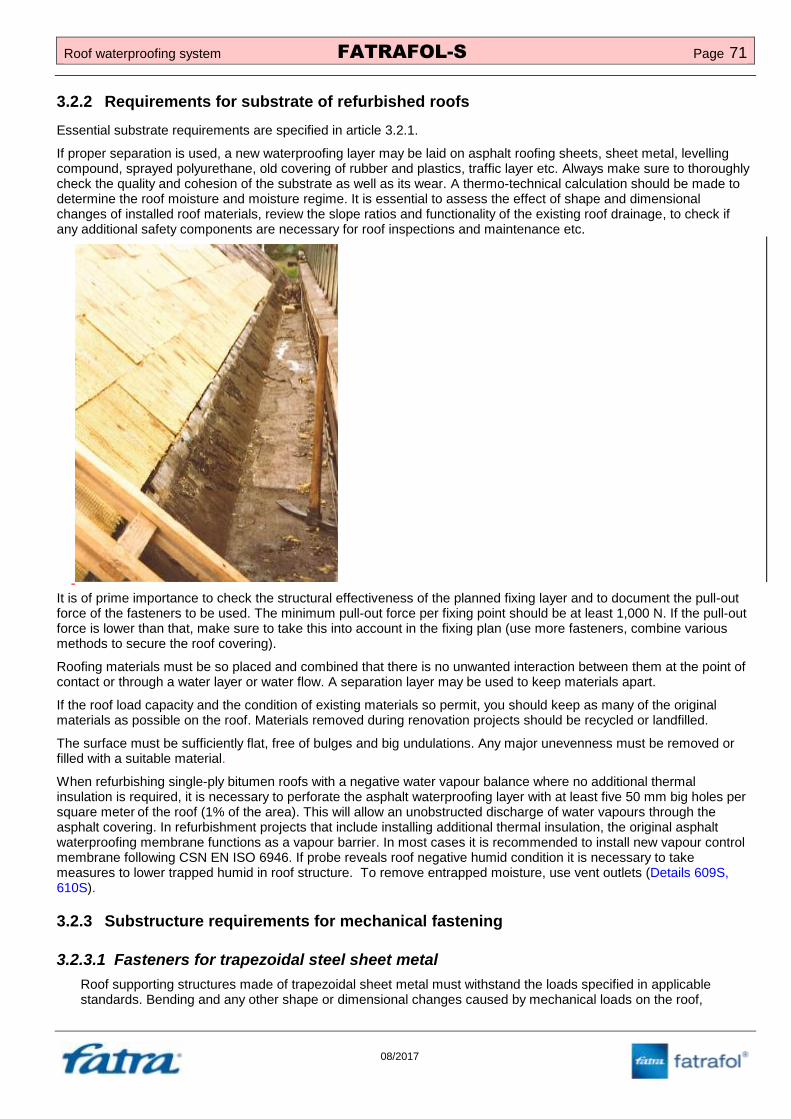
Roof waterproofing system FATRAFOL-S Page 71
08/2017
3.2.2 Requirements for substrate of refurbished roofs
Essential substrate requirements are specified in article 3.2.1.
If proper separation is used, a new waterproofing layer may be laid on asphalt roofing sheets, sheet metal, levelling compound, sprayed polyurethane, old covering of rubber and plastics, traffic layer etc. Always make sure to thoroughly check the quality and cohesion of the substrate as well as its wear. A thermo-technical calculation should be made to determine the roof moisture and moisture regime. It is essential to assess the effect of shape and dimensional changes of installed roof materials, review the slope ratios and functionality of the existing roof drainage, to check if any additional safety components are necessary for roof inspections and maintenance etc.
It is of prime importance to check the structural effectiveness of the planned fixing layer and to document the pull-out force of the fasteners to be used. The minimum pull-out force per fixing point should be at least 1,000 N. If the pull-out force is lower than that, make sure to take this into account in the fixing plan (use more fasteners, combine various methods to secure the roof covering).
Roofing materials must be so placed and combined that there is no unwanted interaction between them at the point of contact or through a water layer or water flow. A separation layer may be used to keep materials apart.
If the roof load capacity and the condition of existing materials so permit, you should keep as many of the original materials as possible on the roof. Materials removed during renovation projects should be recycled or landfilled.
The surface must be sufficiently flat, free of bulges and big undulations. Any major unevenness must be removed or filled with a suitable material.
When refurbishing single-ply bitumen roofs with a negative water vapour balance where no additional thermal insulation is required, it is necessary to perforate the asphalt waterproofing layer with at least five 50 mm big holes per square meter
of the roof (1% of the area). This will allow an unobstructed discharge of water vapours through the
asphalt covering. In refurbishment projects that include installing additional thermal insulation, the original asphalt waterproofing membrane functions as a vapour barrier. In most cases it is recommended to install new vapour control membrane following CSN EN ISO 6946. If probe reveals roof negative humid condition it is necessary to take measures to lower trapped humid in roof structure. To remove entrapped moisture, use vent outlets (Details 609S, 610S).
3.2.3 Substructure requirements for mechanical fastening
3.2.3.1 Fasteners for trapezoidal steel sheet metal
Roof supporting structures made of trapezoidal sheet metal must withstand the loads specified in applicable standards. Bending and any other shape or dimensional changes caused by mechanical loads on the roof,

Page 72 FATRAFOL-S Roof waterproofing system
08/2017
temperature, and shape and dimensional changes of roof layers must not have an adverse effect on the roof function or on related structures. Bending must not exceed limits set by applicable standards. The supporting structure design must take into account the interaction of some metals (see CSN 73 3610).
Waterproofing membranes must not be placed directly on trapezoidal sheet metal without a suitable cushioning layer that can withstand the pressure during the hot-air welding process (minimum compressive strength: 60 kPa at 10% compression).
Waves in trapezoidal steel sheet metal must not be filled with lightweight concrete. Remove dirt and standing water from top (crest) and bottom (trough) of wave before trapezoidal sheets get covered by other layers. Tread all cut metal surfaces that will be installed to roof structure against corrosion.
3.2.3.2 Fasteners for concrete and reinforced concrete
The substrate must be continues (unbroken) and sufficiently strong (at least 14 days old). Concrete curing time will prolong in winter time ). Tensile tests must be performed for renovated flat roofs. The substrate must be free of any impurities and unevenness. The surface may be damp but it must be free of puddles, snow and ice.
Dilatation of concrete screed serving as anchoring layer must be done in accordance with CSN 731901.
3.2.3.3 Fasteners for thin concrete prefabricates
The substrate – prefabricate – surface must be unbroken and free of sharp edges and nibs. Open joints must be filled with suitable material. The substrate must be free of any impurities and unevenness. The surface may be damp but it must be free of puddles, snow and ice. For roof restoration, roof substructure static load test describing maximum additional load and way of anchoring is required.

Roof waterproofing system FATRAFOL-S Page 73
08/2017
Anchoring membrane to concrete through thermal insulation
3.2.3.4 Fasteners for porous concrete
The porous concrete substrate (glass concrete, foam concrete and gas concrete) must. It is recommended to always perform a pull out test.
Dilatation must be in accordance with CSN 731901- annex G.
3.2.3.5 Fasteners for wooden substrates
Substructure surface must be continues and must able to withstand intended additional load. All components of the wooden structure (solid timber, large boards with added wood substance) except for cementitious boards must be treated against pests. An appropriate structural measure must be taken to ensure the service life of wooden components that are integrated into a structure with humidity exceeding 16% or that may be subject to additional exposure to water in the structure (e.g. due to condensation). Possible measures include building a two-ply roof with a ventilated air layer, adding a safety waterproofing layer etc. Even with a well ventilated air layer, water vapour condense on the underside of the top ply may appear. The roof deck design must take this phenomenon into account. Wooden load-bearing components should be accessible for inspection, repair or renovation of the wood chemical protection throughout the structure’s service life.
If mechanical fasteners producer does not determines otherwise, wood planks minimum width suitable for mechanical anchoring is 20 mm. For wood particle boards (“OSB boards”) it is 18mm.
Planks must be installed tightly edge-to-edge. Rigid roof boards pressed using wood substances and plywood panels must be installed keeping expansion joints recommended by the manufacturer.

Page 74 FATRAFOL-S Roof waterproofing system
08/2017
OSB boards – recommended fastening and expansion joints:
3.2.3.6 Problematic substrates
Problematic substrates for mechanically fastened roof waterproofing membranes include, in particular, profiled aluminium sheets, roof panels with an integrated thermal insulation layer, thin-walled concrete shells, wood-cement boards, original asphalt sheets on a thermal insulation layer of EPS panels etc.
It is recommended to conduct pull-out resistance tests for all of these substrates and to verify that their point load capacity is at least 500 N.
Problematic substrates are:
Steel sheet with thickness smaller than 0,63 mm
Aluminium sheet
Concrete screed
Wood-cement board
wood particle boards thinner than 18 mm
3.3 Vapour control layer
Vapour control layers are integrated into roof decks to reduce water vapour diffusion flow from the interior into the roof deck and thus to avoid the condensation of water vapour and its related negative impacts.
Vapour control layers are made of materials with high diffusion resistance. Only materials that can be airtight joined between each other and to penetration and end structures may be used
A vapour control layer made of a vapour control membrane, which is joined gastight, is placed under the thermal insulation layer, towards the inner surface of the roof structure. If a silicate pitched layer is used in the roof deck, the vapour control layer is placed on it. Vapour permeability of layers should increase towards the roof deck surface to ensure gradual removal of water vapour.
Placing a vapour control layer under a monolithic pitched or thermal insulation layer is not recommended unless moisture removal is provided for this layer from the above.
Sandwich panels, profiled sheets, 0.63 mm thick
Fibre cement roof coverings
Aluminium sheet or other fragile substrates

Roof waterproofing system FATRAFOL-S Page 75
08/2017
A protective or separation layer of suitable fleece should be placed on a monolithic or prefabricated base or pitched layer of silicate materials, under the vapour control layer made of lightweight membranes.
To dimension the vapour control layer, make a moisture calculation. If FATRAFOL open-diffusion membranes are used and if the roof deck does not have old coverings made of asphalt sheets or another closed-diffusion layer under the waterproofing membrane, a vapour control membrane with a equivalent diffusion length of 50 m is suitable for most applications.
If a thermal insulation layer of foam glass is used, no vapour control layer need be installed. However, always check if a vapour control layer may be omitted by making a thermo-technical calculation, assessing the water vapour balance in the roof structure and arranging the roof deck layers properly with respect to heat transfer coefficient and water vapour diffusion resistance.
Joints must remain fully functional on the entire layer throughout the roof service life or the design calculation must reflect their potential lack of tightness.
Perforation caused by fasteners does not have an effect on the overall functionality. The actual perforation in PE membranes is negligible since openings are filled by fastener shafts. In asphalt vapour control layers, the perforation value is even lower.
A vapour control layer may also function as an airtight layer or a securing waterproofing layer. If a vapour control layer also functions as a securing waterproofing layer, it must be drained. Outlets should be connected to a separate downpipe, known as ‘dry riser’ or, via a separate connection with a non-return flap, to a shared downpipe of the drainage system of the main waterproofing layer. Securing waterproofing layer minimum slope towards a drain fixture is 1%.
3.4 Thermal insulation
Thermal insulation must meet requirements placed on flat roofs, be heat-resistant and dimensionally stable, must not be subject to volume and shape changes, must be made of materials with reduced absorption of water and humidity and must be resistant to biological corrosion.
Thermal insulation materials must be resistant to the loads they are exposed to in roofs for specific time period.
Thermal insulation layers made of panels must be unbroken. Where the warping or dimensional and shape changes of the substrate or thermal insulation boards are likely to create gaps between thermal insulation boards, then boards with a half-groove should be used. Boards should be placed in a brick pattern.
If a thermal insulation layer includes more boards placed atop each other, gaps of the upper layers should not align with gaps of the bottom layers.
A thermal insulation layer for inverted roofs must be made of a water resistant material that is guaranteed by the manufacturer to maintain its thermal insulation properties when exposed to water. Low water absorption materials should be used.
In order to ensure sufficient substrate rigidity, which is necessary also for joining roof waterproofing membranes, thermal insulation boards must meet the following requirements:
Compressive strength at 10% compression according to EN 826 ≥ 0.06 N/mm2 (60 kPa). This requirement
applies either to homogeneous materials or to the top layer of multi-layered or composite products.
Behaviour under point load according to EN 12430 ≥ 500 N at 5 mm deformation.

Page 76 FATRAFOL-S Roof waterproofing system
08/2017
3.5 Separation layer
Separation layers protect waterproofing membranes and separate them from any layers that may, in case of direct contact, interact negatively with them.
FATRAFOL waterproofing membranes without back-fleece must be fully separated from all types of
substrates. Recommended separation layers described in In case the surface is smooth without risk of mechanical or chemical damage of the membrane and at the same time separation layer is not needed due to external fire resistance, it is possible to skip separation layer. Typical detail is the inner vertical surface of parapet made of sandwich panels.
Table 6.
In case the surface is smooth without risk of mechanical or chemical damage of the membrane and at the same time separation layer is not needed due to external fire resistance, it is possible to skip separation layer. Typical detail is the inner vertical surface of parapet made of sandwich panels.
Table 6: FATRAFOL S system separation layers
Substructure
Mechanically fastened roof coverings
with fire resistance requirement in
accordance with EN 13501-5+A1
Mechanically fastened roof coverings
without fire resistance requirement in
accordance with EN 13501-5+A1
and roofs with stabilisation layer
Concrete non-woven textile min. 200 g/m
2 + glass
fibre fleece min. 120 g/m2
non-woven textile min. 300 g/m2
Bituminous sheets non-woven textile min. 200 g/m
2 + glass
fibre fleece min. 120 g/m2
non-woven textile min. 300 g/m2
EPS and XPS
insulation glass fibre fleece min. 120 g/m
2
non-woven textile min. 200 g/m2 + glass
fibre fleece min. 120 g/m2 *)
MW and PIR/PUR
insulation separation is not required separation is not required
Wood planks non-woven textile min. 300 g/m
2 + glass
fibre fleece min. 120 g/m2
non-woven textile min. 300 g/m2
OSB and other wood
particle boards glass fibre fleece min. 120 g/m
2
a) wood boards without groves and tongues - non-woven textile min. 300 g/m
2 + glass fibre fleece min. 120 g/m
2
b) wood boards with groves and tongues - non-woven textile min. 200 g/m
2, or
completely without separation
*) FPO do not require separation
3.6 Main waterproofing layer
The main waterproofing layer prevents the ingress of atmospheric, service or technological water into or under the roof.
The position of the layer depends on the required roof structure performance.

Roof waterproofing system FATRAFOL-S Page 77
08/2017
The design of the main waterproofing layer must be based on roof purpose, fastening method, fire requirements along with reliability, durability and feasibility. The choice of fasteners for the waterproofing layer must be based on the required load capacity during the roof service life.
The main waterproofing layer of the FATRAFOL-S system is suitable also for zero-slope roofs. Although standing water and puddles on a roof covering do not have a negative impact on the performance and service life of FATRAFOL waterproofing membranes, it is recommended to slope the roof covering for structural reasons. The recommended slope depends on the roof structure use (see CSN 73 1901).
The main waterproofing layer of the FATRAFOL-S system usually consists of a single layer of the specified roofing membrane type.
3.6.1 Choosing a suitable membrane type for the main waterproofing layer
A manufacturer of PVC-P and FPO based waterproofing membranes, Fatra, a.s., Napajedla offers 5 types of PVC-P and 3 types of FPO waterproofing membranes within the FATRAFOL-S system. Their suitability for use as the main waterproofing layer in roof decks depends on their technical specifications. To choose the most suitable membrane type for your application, refer to the recommendations in table 7. In practice, it is possible and usually also beneficial to combine some types of membranes on the roof, taking into account their typical technical properties and performance.
Waterproofing membranes for the top layer must be resistant to UV radiation. Membranes with limited resistance to UV radiation must be so installed that no direct or reflected solar radiation may fall on them during their service life. Protection against UV radiation must also be provided during the construction process. Any materials with limited resistance to weather must be installed within the time specified by their manufacturer.
The required fire performance depends on whether the roof structure is to bear loads or not. A load-bearing structure must have the fire resistance required for the specific type of structural part (DP1, DP2 or DP3). No fire resistance assessment is necessary for non-load-bearing structures and you may proceed to the next articles (CSN 73 0810/Z1).
The roof deck composition in a fire hazard area must meet the requirements of the BROOF(t3) class of external fire performance for roofs. Outside the fire hazard zone the requirements of the BROOF(t1) class must be met.
Surface temperature is one of the many factors to consider when choosing a membrane type. This depends on the membrane surface colour and structure and on the base layer thermal conductivity. Dark membranes increase the covering surface temperature, which may reach up to 80°C. Take this into account when choosing your thermal insulation material. Membrane surface temperature can be increased by sun reflexion from surrounding surfaces (for example sun reflexion of facade, glass surfaces) On the other hand, light-coloured membranes reflect solar radiation and are used, for example, for some types of photovoltaic panels.
On flat roofs and in protection and traffic layers of roofs, water accumulates during rain and snow thaw, exerting hydrostatic pressure on the roof. For such conditions, the minimum membrane thickness is 1.5 mm (recommended under CSN P 73 0606).
Another criterion to consider when choosing a waterproofing membrane is the estimated corrosive load and the interaction of materials. Corrosive load on a roof is largely due to chemical, thermal, biological, electromagnetic or atmospheric effects, the surrounding environment and the use of and environment in the building. Typical examples of

Page 78 FATRAFOL-S Roof waterproofing system
08/2017
interaction of materials include a direct contact between expanded polystyrene and a PVC-P membrane. If not separated sufficiently, both materials may have a significantly shorter service life.
Table 7: Possible use of FATRAFOL roof waterproofing membranes
+ + Primary use + Suitable for use – Unsuitable for use
*) Suitability for use in a specific application should be consulted with the manufacturer.
3.6.2 Securing waterproofing membranes
3.6.2.1 Protecting membranes from internal forces
All membranes made of plasticised PVC and FPO are subject to dimensional changes depending on temperature and exposure time. The causes of this phenomenon lie in the production technology, thermal expansion and long-term structural changes in the membrane material.
While dimensional changes take place throughout membrane service life, the biggest ones (mostly contraction) occur just after membranes are unrolled from a tightly wound roll and when freely lying membranes are first warmed by sunshine or another source of heat. Therefore, after unrolling membrane sheets on the roof, you should leave them lie unconnected and unfastened for some time. In warm and sunny weather, the process takes a few minutes only, otherwise allow approximately half an hour.
To avoid further effects of internal forces, the covering must be fastened to a solid substrate at the perimeter or in the structure base, in accordance with applicable specifications. Likewise, a membrane must be fastened in roof valleys, when waterproofing valley and parapet gutters, at the perimeter of projecting structures, along all roof deck penetrations as well as in places where roof contraction may negatively affect the performance and stability of the covering (creation of fillets and ‘trampolines’). Such perimeter fastening is necessary also when the covering is later loaded with a stabilisation, protection or traffic layer or with green layers. In roofs with the standard arrangement of layers and a mechanically fastened waterproofing membrane, additional membrane contraction has also a positive effect on the planarity of the roof external surface by eliminating the undulations that cannot usually be avoided during the waterproofing layer installation.
From a structural point of view, dimensional changes result from forces acting, with varying intensity, inside the membrane in all directions at the level at which the membrane is unfolded. Tension generated in any point of the covering depends on the dimensions and shape of the surface being waterproofed and on the position of fixed elements (fasteners, protruding structures, penetrations, rainwater outlets etc). Fasteners in the roof deck structure should preferably be tensioned in a manner that guarantees a better transfer of active forces, i.e. subjected to pull rather than bending stresses.
To meet the above requirements, use linear plastic-coated metal profiles to which the membrane may be welded homogeneously. Basic shapes of plastic-coated metal profiles are given in table 5. Maximum distance between fasteners is 250 mm (plastic-coated metal profiles fasteners density is 4,5 pc/m when installed edge to edge with 2 mm
Roof system
type/waterproofing
membrane type
Unprotected membrane, exposed directly to
weather
Membrane protected by a
loading or service layer Recommended primary use
of membrane Mechanically fastened
Bonded
Loaded with
aggregate,
pavers
With green
layers In fire hazard
areas Outside fire
hazard areas
FATRAFOL 807 – + + + – – Renovation of asphalt roofs
FATRAFOL 807/V – – + + – – Bonded systems
FATRAFOL 810 T1
FATRAFOL 810/V T2 – + + – +
*) +
*)
Standard roofs with mechanically fastened covering
FATRAFOL 810 T1
FATRAFOL 810/V T3 + + + – + *) +
*)
Standard roofs with mechanically fastened covering
FATRAFOL 814 – + + – – – Top, pedestrian traffic layers of balconies and terraces
FATRAFOL 818/V-UV – – – + + ++ Roofs with loading layer and traffic layer
FATRAFOL P 916 – + + – – – Roofs with mechanically fastened covering
FATRAFOL P 918 – + – + + + + Roofs with loading layer and green roofs
FATRAFOL P 918/SG – + + – + + Photovoltaic roofs

Roof waterproofing system FATRAFOL-S Page 79
08/2017
expansion gap). Blind rivets, dowels, wood screws, screws, nails etc may be used as fasteners, depending on the substrate. Adjacent fasteners must be spaced at a minimum of 150 mm. If installing profiles of a greater width, place fasteners in two lines, following a zigzag pattern.
When fastening perimeter profiles, make sure their length expansion is possible. Under CSN 73 3610, the maximum length of an expansion section is 6 m. If using plastic-coated and film-coated sheet metal, standard sheet metal joints and expansion modifications are not possible.
In addition to perimeter fastening, all PVC-P membranes, with only exception mentioned in art. 2.1.9.1.3, designed for mechanical fastening must be secured against internal forces also within the roof field. It is possible to adjust distance between fasteners when fastening membrane to trapezoidal sheets to its wave length.
3.6.2.2 Fastening of internal corner flashing
Internal corner flashing must be mechanically fastened to either load bearing horizontal or vertical substrate. The most common method of fastening to steel deck roofs is fastening to horizontal surface using screws or combination screw + plastic tubes. In case of using plastic sleeves it is necessary to pre-drill holes in horizontal part of internal corner flashing with same spacing as steel deck ribs. Plastic-coated sheet metal internal corner minimum developed width, used in system Fatrafol -S and produced by manufacturer, is 70 (50/20) resp. 100 mm (60/40). It is not recommended to use arm of the internal corner smaller than 40 mm, if it’s intended for mechanical fastening or welding membrane to it.
Following rules apply for fastening of internal corner flashing to vertical parapets made of sandwich panels.
If the sheets of FATRAFOL membrane are oriented perpendicular to parapet, common fasteners such as TEX screws, or countersunk screw, flat head screw an similar can be used. The wind uplift forces are eliminated by fasteners in the field of the roof.
If sheets of FATRAFOL membrane are oriented parallel to parapet, fasteners recommended by manufacturer for given thickness of steel should be used. Riveting is an alternative. The maximum distance between the nearest fastening row and the inner surface of the parapet should not exceed 950 mm. Wind load calculation
can confirm bigger distance (Detail 410S). Fasteners for fastening internal corner flashing transfer not only internal forces but also external forces from wind.
3.6.2.3 Securing the roof covering against external forces
Wind uplift is the most significant external force affecting the roof covering surface. The uplift force depends on many factors, of which the critical are in particular the terrain category, geographic position of the building, and building height. Other influencing factors are for example the parapet height and roof pitch. The volume of uplift forces is different in individual roof zones defined in CSN EN 1991-1-4 Eurocode 1: Structure loads – Part 1-4: General loads – Wind loads, see Figure 2. Uplift forces from the wind affecting the roof cover must always be prevented using one of the conventional fixation methods, i.e. mechanical fastening in the bearing base, additional load, gluing or other suitable method.
If there is no reason to use other fixation method to eliminate uplift forces, mechanical fastening in the bearing base is preferred in the FATRAFOL-S system as compared with other fixation types.
Parapet plating - detail
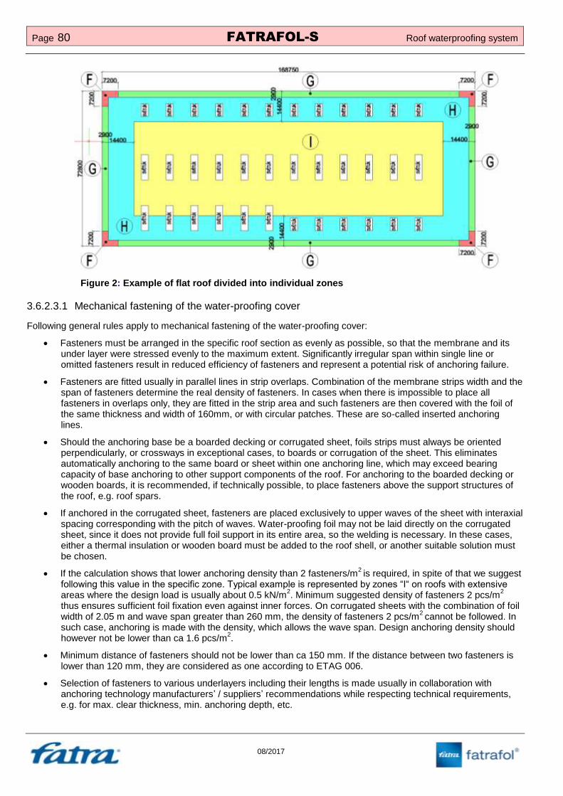
Page 80 FATRAFOL-S Roof waterproofing system
08/2017
Figure 2: Example of flat roof divided into individual zones
3.6.2.3.1 Mechanical fastening of the water-proofing cover
Following general rules apply to mechanical fastening of the water-proofing cover:
Fasteners must be arranged in the specific roof section as evenly as possible, so that the membrane and its under layer were stressed evenly to the maximum extent. Significantly irregular span within single line or omitted fasteners result in reduced efficiency of fasteners and represent a potential risk of anchoring failure.
Fasteners are fitted usually in parallel lines in strip overlaps. Combination of the membrane strips width and the span of fasteners determine the real density of fasteners. In cases when there is impossible to place all fasteners in overlaps only, they are fitted in the strip area and such fasteners are then covered with the foil of the same thickness and width of 160mm, or with circular patches. These are so-called inserted anchoring lines.
Should the anchoring base be a boarded decking or corrugated sheet, foils strips must always be oriented perpendicularly, or crossways in exceptional cases, to boards or corrugation of the sheet. This eliminates automatically anchoring to the same board or sheet within one anchoring line, which may exceed bearing capacity of base anchoring to other support components of the roof. For anchoring to the boarded decking or wooden boards, it is recommended, if technically possible, to place fasteners above the support structures of the roof, e.g. roof spars.
If anchored in the corrugated sheet, fasteners are placed exclusively to upper waves of the sheet with interaxial spacing corresponding with the pitch of waves. Water-proofing foil may not be laid directly on the corrugated sheet, since it does not provide full foil support in its entire area, so the welding is necessary. In these cases, either a thermal insulation or wooden board must be added to the roof shell, or another suitable solution must be chosen.
If the calculation shows that lower anchoring density than 2 fasteners/m2 is required, in spite of that we suggest
following this value in the specific zone. Typical example is represented by zones “I“ on roofs with extensive areas where the design load is usually about 0.5 kN/m
2. Minimum suggested density of fasteners 2 pcs/m
2
thus ensures sufficient foil fixation even against inner forces. On corrugated sheets with the combination of foil width of 2.05 m and wave span greater than 260 mm, the density of fasteners 2 pcs/m
2 cannot be followed. In
such case, anchoring is made with the density, which allows the wave span. Design anchoring density should however not be lower than ca 1.6 pcs/m
2.
Minimum distance of fasteners should not be lower than ca 150 mm. If the distance between two fasteners is lower than 120 mm, they are considered as one according to ETAG 006.
Selection of fasteners to various underlayers including their lengths is made usually in collaboration with anchoring technology manufacturers’ / suppliers’ recommendations while respecting technical requirements, e.g. for max. clear thickness, min. anchoring depth, etc.

Roof waterproofing system FATRAFOL-S Page 81
08/2017
To achieve full efficiency of the fastener, its correct placement into the base is necessary, which must be always min. 10 mm from the strip edge. Failing that, the load capacity of the fastener and thus the foil stability are reduced.
For concurrent stabilization of the water-proofing and thermal insulation layer of roofs with conventional arrangement of layers, it is necessary to take into account also dimensions of used components of the thermal insulation when defining the spacing of fasteners. In central areas of the roof where a foil width of 2,05 m is often used, the thermal insulation must in principle be fastened separately. Thermal insulation manufacturers usually suggest independent fastening of thermal insulation parts with the density of 2 pcs/m². Fasteners designed for independent stabilization of thermal insulation layers are not counted towards statically efficient anchors of the water-proofing cover.
When height of parapet doesn´t exceed 600 mm, vertical membrane is welded only to flashing components at the bottom and on the top of parapet.
One of the following options has to be used when the height of parapet is between 600 and 1200 mm and therefore additional fastening of vertical membrane is required.
Welding the membrane to mechanically fastened horizontal plastic coated metal strip (Detail 510S).
Point fastening and patching with horizontal spacing between 750 and 1000 mm (Detail 511S).
Seam fastening in overlaps (Detail 512S, 513S).
When height of parapet exceeds 1200 mm follow same principles as described above and add one or more horizontal fasteners rows (Details 510, 511, 512, 513S).
3.6.2.3.2 Calculation of wind load and mechanical anchoring proposal
Rated load capacity of a single fastener is defined using test results under ETAG 006, or tension test results performed on the site. Design load capacity of a single fastener is defined as the lowest of all recognized or calculated values.
In case of renewals and anchoring in older underlayers, in particular concrete screed, light concrete, and original wooden decking, but also in thin sheets, it is always necessary to perform so-called tension tests on the roof. Tension tests are performed by selected supplier of the anchoring technology within the technical service. Number of such tests is governed by ETAG 006 recommendation. The tension test supplier defines in the protocol form the design load capacity of the fastener in the underlayer, taking into account safety coefficients under ETAG 006.
Fatra, a.s. provides informative calculations of wind load with the proposal of fasteners for the water-proofing foil on the roofs with FATRAFOL roof foils. Calculations are made for roofs with the area exceeding 400m
2. Small area roofs are
calculated based on individual agreements only. The calculation is not claimable automatically and may be rejected, e.g. due to small roof area. Calculations do not substitute static calculations for execution, which are made by authorised engineer or static designer only.

Page 82 FATRAFOL-S Roof waterproofing system
08/2017
Calculation processing is subject to sending complete details to respective regional business-technical representative or to the following e-mail: [email protected]. Required details are specified in the form ZV-11/2013 that is available in its electronic format at http://www.fatrafol.cz.
Calculations are provided standardly within 7 business days from the receipt of complete details. Any additional change due to ordering party’s requirement (e.g. modification of input parameters) may be subject to a payment on individual basis.
In cases where a static calculation of wind load and an anchoring plan are required for execution, it can be made by authorised engineer or static designer only. Such calculation is subject to a payment.
3.6.2.3.3 Empiric definition of anchoring density
Empiric definition of required density of fasteners is with respect to both, the number of variables on the part of the load and fasteners, problematic and applicable to buildings of smaller area or significance only. Empiric definition of

Roof waterproofing system FATRAFOL-S Page 83
08/2017
anchoring density is mainly of informative nature. By more accurate calculation, significantly lower design anchoring density may be achieved in principle. Table 8 shows the wind load and the min. anchoring density under boundary conditions stated.
Table 8: Empiric definition of anchoring density under various boundary conditions
*) Minimum density of fasteners is rounded up to whole fasteners.
**) Minimum suggested density of ca 2 fasteners/m
2 is based on the need to fix the cover against inner forces, although a smaller number fasteners
is required for elimination of uplift forces from the wind
Figure 3: Wind speed map according to ČSN EN 1991-1-4:2007
Terrain
category
ac. to
CSN EN
1991-1-4
Wind
zone ac.
to CSN
EN 1991-
1-4
Reference
height
(m)
Parapet
height
(m)
Cpi
Roof
slope
(°)
Fastener
admissible
load
capacity
(N)
Wind loads (kN/m2)
Min. fasteners density
(pcs/m2)*)
ZONE
F
ZONE
G
ZONE
H
ZONE
I
ZONE
F
ZONE
G
ZONE
H
ZONE
I
I.
II. 10 0 0 do 5 600 4,06 3,25 1,95 0,32 7 5 3 2
**)
15 0 0 do 5 600 4,42 3,54 2,12 0,35 7 6 4 2**)
III. 10 0 0 do 5 600 4,91 3,93 2,36 0,39 8 7 4 2
**)
15 0 0 do 5 600 5,35 4,28 2,57 0,43 9 7 4 2**)
II.
II. 10 0 0 do 5 600 3,45 2,76 1,65 0,28 6 5 3 2
**)
15 0 0 do 5 600 3,83 3,07 1,84 0,31 6 5 3 2**)
III. 10 0 0 do 5 600 4,17 3,34 2,00 0,33 7 6 3 2
**)
15 0 0 do 5 600 4,64 3,71 2,23 0,37 8 6 4 2**)

Page 84 FATRAFOL-S Roof waterproofing system
08/2017
Figure 4: Definition of terrain categories I and II according to ČSN EN 1991-1-4:2007
Figure 5: Rules for roof´s zones according to ČSN EN 1991-1-4:2007

Roof waterproofing system FATRAFOL-S Page 85
08/2017
Figure 6: Example of roof zones
3.6.2.3.4 Securing membranes with aggregate, traffic layer or a green layer
Waterproofing and other structural layers of the roof deck without UV stabilisation must, throughout their service life, be effectively protected with a stabilisation layer against negative weather effects. The stabilisation layer quality must correspond with the planned roof traffic.
Since loading the roof deck with bulk material or loose pavers fails to fully eliminate internal forces in the membrane (contraction), it is essential to install suitable linear plastic-coated metal profiles at points where the roof suddenly changes its slope and to hot-air weld the membrane to the profiles.
The following options are possible to secure roof layers against negative wind pressure and also meet other performance requirements:
Ballast – usually contains mined and sorted aggregate of grading 16-32 mm (shingles), thickness as per a structural calculation. In perimeter and corner zones of the roof, ballast should be combined with concrete pavers or other measures should be taken to secure both the membrane covering and the ballast against negative wind pressure. In order to secure ballast on a slope of over 6°, reinforce the surface layer, e.g. by bonding, with cement primer or an alternative technical measure, e.g. by using the GEOCEL honeycomb plastic membrane.
Pavers
o Pavers on support pads, known as ‘dry paving’, concrete pavers with minimum recommended dimensions of 400x400x40 mm. PE- or PP-based support pads may be placed directly on the membrane without separation, although it is recommended to put a patch underneath the support. Rubber pads need to be separated from PVC-P membranes. Correction pads should be used to ensure the required flatness of the paver surface.
o If placed on a mortar bed, pavers are usually put on frost-resistant bonding sealer on a reinforced base concrete layer. The base layer must have expansion joints in a 2x2 m grid or as determined by a structural assessment.
o Sub-base for pavers – usually a bed of sand or crushed aggregate of grading 8/16 + 4/8, or only 4/8 mm, minimum layer thickness 20 mm.
o Pavers of elastomeric or plastic panels are typically used to create walkways or as temporary protection of the waterproofing membrane.

Page 86 FATRAFOL-S Roof waterproofing system
08/2017
Stabilisation concrete layers – these are usually made of reinforced oversite concrete, plastic concrete or asphalt concrete with expansion joints. Silicate materials in an unprotected position in the roof deck should have expansion gaps and be separated from adjacent structures with a suitable expansion, separation and drainage layer. The determination of the minimum thickness of stabilisation concrete layers is based primarily on the structural assessment of wind pressure in individual roof deck zones. The typical minimum thickness of these layers is 50 mm for silicate structures and 30 mm for other types of stabilisation layers.
Wooden slats – protecting a waterproofing membrane with wooden slats does not usually meet the specifications required by the structural calculation. The materials must have constant resistance to biological corrosion and be separated from the waterproofing membrane with point or linear components. Such components must not pose an obstruction to smooth removal of rainwater.
Vegetation layer (soil) – the layer thickness depends on the proposed maintenance method and requirements of the plants. A vegetation layer should have a thickness of 80 mm to 150 mm for extensive maintenance and of 150 mm to 1,000 mm for intensive maintenance. The overall thickness of vegetation layers depends on the load-bearing capacity of the underlying roof structure and on the plants to be grown there.
In order to protect roof layers against negative wind pressure, the main protective means must usually be combined with additional ones in perimeter and corner roof zones.
See Table 9 for approximate surface density of the most common types of stabilisation layers.

Roof waterproofing system FATRAFOL-S Page 87
08/2017
Table 9: Approximate surface density of selected loading layers
Stabilisation layer Grading Density, bulk weight
[kg.m-3
]
Plain cement concrete, pavers, terrace pavers 2,300
Tile flooring 2,000
Mined aggregate (shingle) 8 - 22 1,800
16 - 32 1,750
Expanded clay (keramzite) 8 - 16 500
16 - 22 450
Aggloporite 800
Soil (peat) 500
Sand 1,600
When covering a FATRAFOL membrane with any traffic layer, the membrane top surface must always be protected fully from mechanical damage by using synthetic fibre textile with a minimum square density of 300 g.m
-2. The textile
need not be used for traffic layers made of concrete pavers on plastic support pads.
3.6.2.3.5 Securing membranes with adhesives
Within the FATRAFOL-S system, FATRAFOL 807 and FATRAFOL 807/V may be secured against wind uplift with foam polyurethane adhesives. Secure the membrane covering with adhesives in applications where structure do not allow using a different fastening method.
The substrate to which the membrane covering is to be bonded must be strong enough to constantly transfer forces acting on the covering. Bonded substrates must be clean, dry, free of dust, oil, lose or embedded gravel, un-adhered coatings, deteriorated waterproofing membranes and any other materials that reduce the strength of the bonded layers.

Page 88 FATRAFOL-S Roof waterproofing system
08/2017
3.6.3 Joining waterproofing membranes
When installing a membrane covering, the key task is to make entirely watertight and firm joints between waterproofing membrane sheets, membranes and linear plastic-coated metal profiles at the perimeter, and between membranes and accessories (rainwater outlets, vent outlets etc) in order to create a single unit. For hot air welding, hand held and automatic machines are used.
Two technologies are available to make these structural joints:
Hot-air welding – this method is based on the so-called fusion welding, which involves heat-melting contact surfaces of membrane and their simultaneous compression. This is achieved by hot air flowing out of a slot nozzle of a welding machine with continuous temperature control. Move the welding machine gently in the direction of an open joint (with the slot nozzle projecting 3 to 5 mm over the upper membrane edge). Heated contact surfaces must be pressed down immediately behind the nozzle, using a rubber or Teflon roller. Common welding temperatures are 430°C to 600°C for PVC-P membranes and 450 °C to 550°C for FPO membranes. This joining method may be used at ambient temperatures from -5°C for PVC-P/-10°C for FPO up to +40°C,
Wedge welding – this method is similar to hot-air welding, differing only in that the welded surfaces are heated by thermal transfer from a wedge welder. Heated contact surfaces must be pressed down immediately behind the wedge welder by machine rollers. This system is used only for automatic welding machines.
If a proper working process is followed, both methods can create joints with shear resistance of at least 80% of the waterproofing membrane shear resistance indicated by the manufacturer. Hot-air welding must be considered the primary method of joining FATRAFOL membranes. Membrane sheets are welded at their overlaps. If using a hand-
operated welding machine, the weld must be at least 30 mm wide. Most automatic welding machines have a 40 mm wide welding nozzle.
In special cases , it is possible to use cold welding method with use of THF thinners for joining membranes. This method is not very common and can be used only for strait welds in open area, not details. Cold welding method can be used at temperatures above +15°C in dry weather. If possible, hot air welding should be always preferred as method for membrane joining.

Roof waterproofing system FATRAFOL-S Page 89
08/2017
Application of sealing compound is recommended:
On zero slope roofs
On ballasted roofs or roofs with traffic layer where FATRAFOL membrane is not the top layer
In all the details where 3D shaped piece of membrane is installed
In „T“ joints (lenght around 150 mm)
Sealing compound cannot be used to repair unperfect welds. It has mainly a visual function and makes easy to distinguish checked welds from unchecked. Once the weld is done properly it has same reliability and functionality with or without the sealing compound.
Welds may be treated with a joint sealant only after they are checked with a testing needle or another penetrating method, not earlier than 1 hour after welding. To apply the joint sealant, use a PE bottle with a 3 mm wide delivery nozzle for horizontal welds and a 1 mm wide delivery nozzle for sloping and vertical welds.
Mix the joint sealant and, if necessary, adjust its consistency before use. Notes:
1) FATRAFOL 807 and 807/V membranes may only be welded using selected types of automatic welding machines that are capable of making the weld in the limited width area of the loose edge (collar).
2) Most structural types of flat roofs can be categorised by hydro-physical loads caused by pressure water (snow thaw, heavy rain, vacuum method of water drainage, water flooding in case of drainage system failure etc).
3.6.4 Ending a roof covering at the roof perimeter
The roof perimeter may include a parapet, ledge, wall, gutter edge etc. The design should meet the following performance requirements:
Ensuring that wind uplift does not tear off the membrane edge from the substrate and that wind does not get under a non-loaded waterproofing membrane layer.
Eliminating the ingress of rainwater under the covering, even in extreme conditions such as wind-driven rain and snow, a thick layer of thawing snow on the roof, roof flooding when downpipes are clogged with dirt, ice etc.
Securing the covering against internal forces in the waterproofing membrane.
Enabling fluent removal of water vapour from the roof layers.
To end the covering, use perimeter plastic-coated metal profiles (Details 208S, 301S, 302S, 303S, 501S – 507S). When joining the membranes to these profiles, follow the instructions for membrane joining within the roof field.
On a vertical wall, the covering may, depending on circumstances, be ended either directly on the masonry and then plastered to a height above the end of the waterproofing layer, or it may be ended on the surface of existing plasterwork and sealed with permanently elastic sealer. With this type of ending, you must take into account the risk that flowing water may seep through the wall. The height of the upper membrane edge above the covering of the adjacent area must be at least 150 mm (Detail 303S, 304S, 305S). A waterproofing membrane must be ended watertight on the edge of a roof opening if its height above the adjacent area level is less than 150 mm. To ensure the membrane covering is well ended, the edge of the roof opening and the structures below the edge must be sufficiently firm and, if possible, positioned in a single vertical line. When installing additional thermal insulation on a vertical wall, water ingress to the bottom of the thermal insulation must be prevented by welding an additional membrane sheet to the original covering and ending it on the new thermal insulation, as described above.

Page 90 FATRAFOL-S Roof waterproofing system
08/2017
3.6.5 Additional sealing of details
When creating a waterproofing covering at a point where three waterproofed planes intersect (internal corner and external corner), and when waterproofing roof penetrations, follow the two methods described below.
When waterproofing 3D details, first cover the detail with suitable flat cuttings of the membrane. Once prepared (without undulations and stretching), the detail is finished by welding to it a vacuum-shaped piece of suitable kind that will make the entire detail completely watertight. Shaped pieces must always be joined to the base membrane by hot-air welding – they must be welded fully or along their entire perimeter, with the weld being at least 30 mm wide (Detail 211S, 212S).
For circular roof penetrations (vent outlets, pipes etc), use is usually made of shaped pieces, either prefabricated (if the required dimension is available) or made on-site from a homogeneous roofing membrane. The homogeneous membrane should always be at least one degree thicker than the waterproofing membrane. Both types of shaped pieces must be fully hot-air welded to the waterproofing membrane. The upper edge of the shaped piece or of the adjacent vertical sheet on a penetrating PVC pipe is to be welded to the pipe. If the pipe is made of any other material, the upper edge is to be sealed with suitable PU sealer and secured in place with corrosion-proof tape. (Detail 607S, 608S).
All joints of waterproofing membranes described in this chapter should be treated with a joint sealant.
3.6.6 Roof drainage
Rainwater may be drained from the surface of flat roofs either by external drainage components – gutters – or by internal drainage components – rainwater outlets and gutters within the roof field. Drainage components must be designed and dimensioned in accordance with CSN 73 1901 and CSN 73 3610 ‘Design of Sheet Metal Constructions’. The design must take into account snow, frost and ice loads on the roof, according to CSN EN 1991-1-3, CSN EN 12056-3.
3.6.6.1 Linear drainage from roof
Linear drainage means removal of water using eaves, ledge, rooftop or parapet gutters. With this type of drainage, the roof covering is welded at its end to a perimeter plastic-coated metal profile (Detail 503S, 504S, 508S, 601S, 602S). It is not recommended to drain water from roofs using parapet and valley gutters.
The minimum permissible slope of all gutters is 0.5%. If a smaller longitudinal slope is provided, dirt may deposit in the gutter, reducing its capacity.
Downpipes installed outside the building or in unheated areas must be sufficiently protected against freezing, e.g. by heating. Heating cables used for this purpose do not affect the roof covering with their temperature.
The maximum distance of rainwater outlets in gutters or valleys from their ends or the dividing crest in the gutters or valleys should not exceed 15 m.

Roof waterproofing system FATRAFOL-S Page 91
08/2017
3.6.6.2 Point drainage from roof
Two basic options are available for point drainage using rainwater outlets:
Using a PVC-P or FPO rainwater outlet to which the membrane is welded at the roof plane or using a rainwater outlet made of a different plastic with a PVC or FPO collar to which the membrane is weldable (Detail 604S).
Using a PVC-P or FPO corner insert to drain water through a parapet (Detail 605S). This roof drainage method requires installing overflow outlets to address the risk of ice formation in rainwater outlets in the parapet wall.
For safety reasons, we recommend installing at least two separate rainwater outlets on each roof having internal drainage elements. Where only one rainwater outlet is provided to drain water from the roof, you should install an overflow outlet for added reliability.
If the covering includes a vapour control membrane, a two-stage rainwater outlet should be used.
To drain the securing waterproofing structure, follow the instructions for the main waterproofing layer. A securing waterproofing layer should be drained using a separate pipe or at least a separate rainwater outlet. That pipe should also indicate failures of the main waterproofing layer (e.g. transparent plastic, electric alarm).
For smooth finishing, roof rainwater outlets should be at least 0.5 m from adjacent structures (parapets, roof penetrations etc).
Refer to Table 10 for dimensioning of rainwater outlets in the Czech Republic.
Connection collars or shaped pieces of rainwater outlets must always be firmly fastened at their perimeter at the roof plane to the substrate, or the underlying waterproofing layer must be fastened. Otherwise, there is a risk of them being displaced or deformed by internal and external forces.
The membrane must be joined in accordance with relevant instructions. A rainwater outlet should be recessed below the adjacent area to allow smooth drainage of water from the covering even during the maximum expected bending of the load-bearing structure.
If electric heating is not provided to protect a rainwater outlet from freezing, pay attention to the risk of water vapour condensation on the outlet inside the roof and ensure removal of all condensate. The same measure must be taken also for multi-ply roofs or, alternatively, the downpipe must be thermally insulated at the point of penetration through the ventilation and thermal insulation layer.
In case of roofs with a stabilisation layer of bulk material, rainwater outlets must always be protected from being clogged with the material; other outlets must be fitted with a leaf and dirt trap. Rainwater outlets should be so positioned and designed to allow easy inspection and cleaning.
Overflow outlets located in a parapet as protection in case rainwater outlets get clogged must be treated, at the point of penetration through the roof covering, similarly to rainwater outlets. The overflow outlet collar must also be fixed firmly to the substrate. The overflow outlet must be located next to the drained valley, at the lowest point of the waterproofing membrane on the parapet, keeping the required slope.
Fatra, a.s. recommends to design and to use rainwater outlets made of ridged plastic with integrated flange. These rainwater outlets are more reliable and profitable in compare to soft rainwater outlets, which are easy to deform.
Table 10: Rainwater outlets – dimensioning for roof types and required safety coefficients
Pipe diameter [mm] (vertical)
Flow rate [l/s] Green roofs with vegetation layer thickness
Other roofs Up to 100 mm Over 100 mm
DN 70 5.7 380 m2 663 m
2 190 m
2
DN 100 6.3 420 m2 700 m
2 210 m
2
DN 125 9.0 600 m2 1,000 m
2 300 m
2
DN 150 10.0 667 m2 1,110 m
2 333 m
2

Page 92 FATRAFOL-S Roof waterproofing system
08/2017
Note: A safety coefficient of 0.5 applies in cases where strong precipitation or a clogged rainwater outlet may cause water ingress into the building. A safety coefficient of 0.3 applies to buildings requiring extra protection (hospitals, museums, theatres etc).
3.7 Traffic layer
A traffic layer or layers on the roof surface allow using the roof for pedestrian or vehicular traffic, as a roof garden, playground, swimming pool, relaxation area etc. A limited traffic layer is provided also on roofs not open to the public to allow their inspections and maintenance.
1. Vapour control membrane
2. Thermal insulation 3. Geotextile 4. FATRAFOL 818/V
waterproofing membrane 5. Drainage layer
(Fatradren) 6. Loop mat 7. Fatratex geotextile 8. Soil 9. Vegetation layer
Within the FATRAFOL-S system, FATRAFOL 814 with an anti-slip texture may be used as a traffic layer.
The traffic layer surface must be so sloped to allow rainwater to flow smoothly to the drainage system.
Special attention must be paid to balconies and terraces. No puddling may occur on these surfaces. Sloping the roof at more than 3% usually prevents puddling.
A waterproofing layer covered with other layers or not accessible for cleaning should be resistant to root penetration. This is a mandatory requirement for vegetation roofs and roof gardens.
Traffic layers located above a waterproofing layer and consisting of ballast, pavers on support pads or pavers in ballast, layers with a reinforced concrete slab or with bonded pavers, vegetation layers etc that also serve as stabilisation against external forces are described in article 3.6.2.3.3
Additional components:
Reinforced concrete or plastic containers for soil and plants
Special structures, shades, visual or protective structures
Combinations of above layers and structures

Roof waterproofing system FATRAFOL-S Page 93
08/2017
4 Technical preparation for installation
4.1 Documentation for installation preparation
Preparatory works for installation may be based on project documentation (usually available for new buildings or general renovations) or survey results.
If project documentation is available, especially the following is necessary to get ready for roof covering installation:
Technical report
Structural assessment of roof load-bearing capacity
Drawings - Roof plan with dimensions and slopes of roof areas - Characteristic roof cross-sections - Detailed design of roof structures including their thicknesses - Drainage method - Expansion joints
Fastening method
Bill of quantities
Planned use and maintenance of the roof
If project documentation is unavailable or incomplete (e.g. ‘building permit documentation’) and in case of any refurbishment, it is necessary to conduct a roof survey, measure the roof, consult the details with the designer and customer, probe the roof and perform tensile tests of the proposed fasteners in order to establish:
The composition, dimensioning and condition of individual roof deck layers, in particular the fixing and thermal insulation ones (thermal and technical assessment),
Roof dimensions and shape,
Roof height above the ground,
Lengths of plastic-coated metal profiles,
Height, shape and composition of parapets,
Quantity and dimensions of roof penetrations including dimensions of rainwater outlets and their connection to downpipes,
Additional adjustments to the roof covering,
Any other requirements (thermal insulation of penetrations, substrate ventilation, positioning of rainwater outlets, expansion joints between traffic layers, slope etc) ,
The maximum possible load on the roof and the positioning of safety components.
4.2 Getting ready for installation
The preparation for installation includes:
Choosing the right waterproofing membrane for the main area and supplementary membrane types,
Determining the method to secure the covering against external and internal forces,

Page 94 FATRAFOL-S Roof waterproofing system
08/2017
Specifying the required substrate treatment (see article 3.2.1),
Determining the roof deck composition,
Calculating the area of individual roof deck zones (based on known or established dimensions),
Determining the types and dimensions of perimeter profiles (see article 3.6.4),
Determining the types, positions and density of fasteners if mechanical fastening is used (see article 3.6.2.3.2),
Determining the type, thickness and position of the stabilisation layer within the roof field,
Choosing the adhesive depending on the substrate structure quality, and positions and coverage in individual roof zones,
Determining the types and quantity of shaped pieces, rainwater outlets and vent outlets,
Specifying the overall material consumption (see Table 11),
Calculating the quantities or costs, or drawing up a budget if necessary, based on the labour required, installation time and all relevant costs associated with the installation (based on the contractor’s experience and the calculation formula shown in Decree 21/1990 Coll. as amended).
Table 11: Approximate material consumption
Material Installation method Consumption per
m2 of roof
Note
FATRAFOL membrane 50 mm overlap 1.07 m2
Width and 1,300 mm 100 mm overlap 1.12 m2
FATRAFOL membrane 50 mm overlap 1.06 m²
Width and 2,050 mm 100 mm overlap 1.08 m²
FATRAFOL membrane 50 mm overlap 1.08 m2
Width 1600 mm 100 mm overlap 1.14 m2
FATRAFOL membrane Width 1600 mm
50 mm overlap 1.06 m2
100 mm overlap 1.10 m2
Joint sealant Securing of all joints (3 mm
wide delivery nozzle) 0.008 kg 1 kg per approx. 130 m
2 of roof
Fasteners for plastic-coated sheet metal
~4.5 pcs/1 running metre - Typical centre-to-centre distance of fasteners: 20 – 25 cm
Sealers Depending on length sealed (0.031.d/P) kg 1 cartridge per 13 running meters
d - Length sealed [m] P - Roof area [m
2]

Roof waterproofing system FATRAFOL-S Page 95
08/2017
5 TECHNOLOGICAL PROCEDURES
5.1 EXTERNAL CONDITIONS FOR WATERPROOFING WORKS
5.1.1 Site readiness
Site takeover, i.e. typically a takeover of a delineated site under Government Regulation 591/2006 Coll., on minimum occupational health safety requirements at construction sites, and of completed load-bearing structures, all end, perimeter and penetrating structures and other firmly attached components, is made by the contractor’s authorised representative (site manager, shift supervisor) in the presence of a site manager representing a superior contractor, the investor’s technical supervisor and other authorised persons.
As part of site takeover, a visual inspection must be made of completeness and slope of base structures and parapets, of skylights and all roof penetrations. Make sure the situation on site corresponds to the current project documentation and the fixing plan.
Works should not commence until the owner’s technical supervisor accepts the base structures. Site takeover must be noted in the construction log, together with the following:
Date and time of site takeover
Exact site description using layout axes (map or sketch)
Site conditions in terms of OH&S, fire prevention and EMS
Number of skylights and steel supports for technological equipment and their conformity with current project documentation
Defects and outstanding works, if any
Signatures of those handing over and taking over the site
Images should be taken of the site at the time of takeover.
Key items to be provided and determined as part of a site takeover process:
A material storage location and protection of materials from mechanical damage, weather and theft
Safe access to the site and place of installation
A safe and cost-effective method of horizontal and vertical transport
Space for materials on the load-bearing or base structure, subject to permissible load
230/400 V connections in accordance with current regulations, including electricity meters
A waste management system (sorting, environmentally friendly disposal, certificates)
Necessary measures in accordance with the site rules and safety, legal and sanitary regulations and standards
Methods to coordinate simultaneous and related construction works and other operations on the roof deck (considering the traffic on complete roof deck sections that have not been handed over to the client as yet)
Performing tightness tests and demonstrating work quality – handover of roof sections

Page 96 FATRAFOL-S Roof waterproofing system
08/2017
5.1.2 Working conditions
PVC-P and FPO membranes may be installed at an ambient temperature of no less than -5°C *) and -10°C
respectively. At temperatures below +5°C, you should first warm unwound waterproofing membranes in a heated room as close to the place of installation as practicable. Works must not be carried out in rain, snow, frost and strong wind.
Fitters may only step on laid waterproofing membranes if wearing soft-soled shoes that prevent mechanical damage to the membrane, ensure safe treading on the membrane without the danger of slipping and meet the safety requirements regarding personal protective equipment.
It is necessary to remove dirt, small object, stones and asphalt stains form boots soles before entering roof area with membrane.
Access by any other persons to laid membranes must be reduced to a minimum. No movement of light construction equipment and no transport and storage of heavy loads is allowed on an unprotected membrane.
Transport routes for people, construction materials and equipment on a finished roof covering, especially on single-ply roofs with the standard arrangement of layers and rigid mineral wool boards for thermal insulation, must be covered with firm material (e.g. OSB boards) to prevent destruction of the thermal insulation. The same protection must be provided where technical equipment is installed and heavy loads temporarily stored.
*) The lowest application temperature for FATRAFOL 814 is +5°C.
5.2 Installing a roof covering
The installation of a FATRAFOL-S system roof covering includes the following sequence of steps:
A visual inspection and, if necessary, levelling and sweeping the substrate
Installing a suitable vapour control layer
Laying a thermal insulation layer (usually two layers with overlapped joints)
Fastening thermal insulation boards to the substrate
Laying base, protective and separation layers of non-woven biocide textile
Installing perimeter profiles of FATRANYL plastic-coated sheet metal or FPO-coated sheet metal
Laying a FATRAFOL waterproofing membrane – dimensional stabilisation
Fastening the membrane to the substrate (mechanical fastening, bonding)
Joining the membranes at overlaps (by a hot-air welding machine or wedge welder)
Waterproofing roof penetrations
Installing end elements
Treating joints with a joint sealant
Treating the roof covering end components, on projecting structures, with permanently elastic PU sealer

Roof waterproofing system FATRAFOL-S Page 97
08/2017
Depending on specific on-site conditions, some jobs may be skipped or the tasks below may follow:
Testing the covering tightness (submersion test, vacuum test of welds known as ‘bubble emission technique’ under EN 1593 + Amendment A1, high-frequency voltage, coloured smoke, impedance defectoscopy etc)
Applying an upper protective layer (aggregate etc)
Applying a traffic layer (pedestrian or vehicular traffic roofs or roofs having another specific function)
Applying vegetation layers for roof gardens
Installing a lightning conductor, TV aerials etc
5.2.1 Installing a vapour control layer
A vapour control layer should be installed on an unbroken substrate. If installed on a broken substrate, joints of the layer must be placed on a firm surface.
If using a PE membrane as a vapour control layer, lay it loose on the base layer, keeping both side and end overlaps with the width recommended by the manufacturer, usually at least 100 mm. Use specific tape to join, in a vapour-tight manner, the overlaps of neighbouring sheets to each other and to all penetrating and end structures and structural components. The surface of joined areas must be clean, dry and free of dust and impurities.
Before installation of a vapour control layer of bitumen sheets, the substrate is usually treated with an adhesion primer. Follow the manufacturer’s instructions to connect the layer to all penetrating and end structures and structural components. Bitumen sheets are usually used as a vapour control layer for concrete substrates and for adhered systems.
On parapets and projecting structures, a vapour control layer must reach at least to the level of the upper surface of the thermal insulation layer.
If a vapour control layer functions simultaneously as an airtight layer, it must not be perforated by roof fasteners.
5.2.2 Installing a thermal insulation layer
Thermal insulation boards are to be installed on a prepared, sufficiently firm and planar substrate that has the required or recommended slope. Bear in mind that if the substrate does not have the required slope, this will have a negative impact on the waterproofing layer surface (risk of puddling). The boards must always be installed in accordance with the manufacturer’s instructions.
Thermal insulation layers made of rigid pressed boards must be joined tightly edge-to-edge or in a brick-like manner. Some types of thermal insulation boards are joined using a half-groove. In case of single-layer mineral fibre insulation, all boards must have an identical direction. If trapezoidal sheet metal is used as a substrate, you should place the boards with their longer side perpendicularly to the profiles in the sheet metal.
If the substrate has a zero slope, pitched thermal insulation boards may be used for sloping. These boards are installed on the first thermal insulation layer, having the minimum design dimensions.

Page 98 FATRAFOL-S Roof waterproofing system
08/2017
Make sure gaps are sufficiently covered if installing two layers of thermal insulation boards. Gaps between thermal insulation boards and/or perimeter and penetrating structures may be up to 5 mm wide as this width usually has no effect on their thermal insulation properties.
If thermal insulation boards are not sufficiently secured with waterproofing membrane fasteners or a loading or traffic layer, they must be secured and fastened to the substrate mechanically or by bonding. In case of single-ply roofs with the standard arrangement of layers, thermal insulation boards must be fastened separately. If producer does not specify amount, use at least 2 fasteners per m². These fasteners are not included in the number of structural fasteners, i.e. the covering still needs to be secured against internal forces (at least 2 fasteners per m²).
Thermal insulation boards made of foam glass feature zero absorption but they must not be fastened mechanically to the substrate and no waterproofing layer may be fastened through them.
In justified cases, e.g. multi-ply roofs or a bonded system, thermal insulation boards are bonded using organic PU-based adhesives, cold asphalt varnishes, or alternatively fixed on special self-adhesive or easily fused asphalt sheets. The boards may be bonded in points or lines, and the adhesive must cover an area specified by the adhesive manufacturer (the bonded surface must provide stabilisation against external forces).
5.2.3 Installing a base, protective and separation layer
Sheets of base and protective fleece as well as glass fibre mats are to be placed on the substrate loosely while keeping side and end overlaps of at least 50 mm in width. Overlaps of fleece sheets are only point-joined by hot-air welding and pressing. Instead of being welded, fibreglass mats are bonded together with self-adhesive tape. Overlaps of a protective layer made of non-woven fleece should be welded fully when applying protective or traffic layers on the waterproofing membrane that may cause displacement of the protective fleece.
If concrete is to be placed over the protective fleece, use an open-diffusion membrane for separation to provide protection from the ingress of cement milk. If possible, the materials must be installed dry. Unfastened fleece should be temporarily loaded (with membrane rolls, boards etc) during windy conditions. A protective and separation layer placed on vertical surfaces is to be fastened using perimeter plastic-coated metal profiles and/or bonded with PU adhesives. The adhesive must not have any negative impact on the micro-ventilation function of this layer.
5.2.4 Installing perimeter profiles
Unless specified in list of flashing material in project documentation, proper material and correct dimension of all roofing flashings is always application company responsibility. Perimeter profiles, i.e. bent plastic-coated metal profiles of various shapes and sizes, are usually installed immediately after the placement of a base or separation fleece layer since they also secure the layer against wind uplift. If fleece-backed membrane (FATRAFOL 807 and 807/V) is used, perimeter profiles are installed after the placement of a waterproofing membrane on the horizontal surface.
The plastic-coated profiles are installed along the entire roof perimeter (eaves, parapet, backing) as well as at points of sudden changes in the base slope (roof valley), at stairs and projecting substrate edges, along gutter edges and at the perimeter penetrations. Round penetration are described in chapter 5.2.6.6.
Pitched boards

Roof waterproofing system FATRAFOL-S Page 99
08/2017
Flashings are usually mounted directly to substrate (without support pieces).Suitable fasteners are used for fixing perimeter profiles. The fasteners must not be spaced more than 250 mm apart (minimum density: 4 fasteners per running meter, i.e. 4,5 pcs/2 m long flashing component).
If wide perimeter profiles are used, they should be fixed alternately in two lines. Fasteners must always reach as far in as a solid and structurally sound layer of the roof deck (concrete, masonry, wood, trapezoidal sheet metal etc).
How to install roofing flashings is described in CSN 73 3610. 2 metre long perimeter profiles are installed edge to edge with 2 mm expansion gap. All flashings must have expansion gap every 6 m in case they are joined with overlap with fastener (same as internal corners profiles). If necessary, use metal shears to adjust the length and shape of sheet metal components; avoid using an angle disc grinder.
At points of structural expansion and connection joints, the perimeter plastic-coated metal profiles must also have an expansion joint.
Except internal and external corner, all flashing components joints must be patched by min. 80 mm wide strip of homogenous membrane. Membrane should be welded only along edges by min. 30 mm weld. This will create 20 mm wide unwelded expantion gap in the axis of the flashing joint (Detail 509S). For external and internal corner flashing joints leave only 20 mm wide unwelded gap without homogenous membrane patch. It is recommended to use 20 mm wide masking tape to create unwelded gap in flashing joint area.
5.2.5 Installing a waterproofing membrane
Installing any type of a waterproofing membrane requires unrolling the roll, letting it dimensionally stabilise, putting it in the right position, correctly fastening the membrane to the substrate and making watertight joints.
Always check all materials before installation. First of all, check if the packaging of the entire pallet is intact. Unroll the rolls and refer to the label to make a visual check of key parameters such as membrane type, dimensions, thickness, number of rolls on pallet. Also check if the product is free of any visible defects such as mechanical damage, colour deviations, deviations from straightness, undulated edges, contamination etc. If any major defects are discovered, do not install the membrane. Keep the label, note the details printed on the sheet edge and contact the distributor for further arrangements. If you fail to do so, the manufacturer disclaims liability for damage caused by deliberate installation of any material that had visible defects and flaws before installation.
5.2.5.1 FATRAFOL 810 and 810/V (mechanically fastened covering)
With their structure, technical parameters and end-use properties, the FATRAFOL 810, 810/V membranes (referred to below as ‘FATRAFOL 810’) are the primary type of a waterproofing membrane designed for mechanical fastening.
The membrane is laid on a substrate covered fully with protective and separation fleece, usually after the placement of perimeter profiles. An exception to the rule is a substrate of rigid thermal insulation mineral fibre boards or of rigid PUR

Page 100 FATRAFOL-S Roof waterproofing system
08/2017
and PIR boards and smooth sandwich panels on which the membrane may be laid without non-woven separation fleece.
Sheets are laid with side and end overlaps. Side overlap width may differ depending on the fasteners used but must not be less than 100 mm. The minimum overlap width for membranes not fastened mechanically is 50 mm. To determine the overlap, refer to the printed identification strip on the membrane face, located 120 mm from its edge. If necessary, cut the sheet length and width with a knife or scissors.
Do not tear membrane sheets. This causes major damage to the reinforcing layer and affects the membrane
strength.
After putting the membrane to the desired position, fasten it mechanically as per the fixing plan, using fasteners designed for that roof section.
An empiric method of dimensioning may be used for flat roof small size flat roofs – see article 3.6.2.2.3. For other buildings it is recommended to calculate each roof individually through a structural calculation under CSN EN 1991-1-4 ‚ ‘Eurocode 1: Actions on structures - Part 1-4: General actions – Wind actions’ and the fasteners must be chosen based on system tests conducted according to ETAG 006 on the basis of which the ‘European Technical Approval’ (ETA) was issued.
Central zone membrane sheets with a width of 1,300 mm and 2,050 mm are usually fastened at their perimeter only.
In perimeter and corner zones where, as demonstrated by a structural design and assessment, perimeter fastening alone fails to secure the covering against negative wind pressure, additional measures must be taken:
Installing sheets of a smaller width,
Point fastening in the sheet area (inserted rows)and then covering the fasteners,
Using fixing discs for fastening.(induction fastening)
For fastener spacing for various sheet widths and for fastener density see Figure and Figure .
The calculation is based on 100 mm sheet overlap

Roof waterproofing system FATRAFOL-S Page 101
08/2017
140
160
180
200
220
240
260
280
300
320
340
360
380
400
420
440
460
480
500
520
540
560
580
2 2,5 3 3,5 4 4,5 5 5,5 6 6,5 7 7,5 8
hustota kotvení [ks/m2]
vzd
ále
no
st
ko
tev [
mm
]
650
8001000
10251300
16002000
2050
šířka fólie [mm]:
pro výpočet bylo uvažováno s přesahem pásů 100 mm
140
160
180
200
220
240
260
7,5 8 8,5 9 9,5 10 10,5 11 11,5 12
Figure 7: Fastener spacing for various sheet widths and fastener density
Figure 8: Fastener spacing for various sheet widths and with typical fastener density
Fastener density [pc/m2]
Membrane width [mm]:
Fa
ste
ner
spacin
g [
mm
]

Page 102 FATRAFOL-S Roof waterproofing system
08/2017
5.2.5.1.1 Fastening a membrane at its perimeter
Fasteners must be so positioned that the washer edge is at least 10 mm from the sheet edge; for finishing of a hot-air welded joint see Figure 9. The minimum and maximum permissible linear spacing of fasteners is 150 and 500 mm respectively (exceptionally 560 mm for trapezoidal sheet metal with waves spaced at 280 mm). Fasteners must be fixed to the substrate in accordance with manufacturer’s instructions. Previously used fasteners must not be reused.
05.10 FATRAFOL for mechanical fastening 04.40 Mineral wool 03.10 Vapour control barrier 01.20 Trapezoidal sheet
07.10 Fastener 09.10 Hot air weld 09.20 sealing compound-recommended
Figure 9: FATRAFOL 810 joint in overlap of sheets fastened to substrate
5.2.5.1.2 Point-fastening a membrane in sheet area
Sheets are fastened in a line in their area, using the same fasteners as for perimeter fastening. A round patch or a minimum 160 mm wide FATRAFOL 810 strip is then welded over the line of fasteners.
See Figure 10 for the waterproofing of a centre-located fastener with a round patch. See Figure 11 for the fastening of a 2,050 mm wide waterproofing membrane, fastener layout and minimum membrane overlaps.
Centre-located fasteners must be aligned along the entire length of the sheet/roof deck zone and oval washers for fasteners must have a uniform direction. A marking string with powder paint may be used to mark the position of a fastener line.

Roof waterproofing system FATRAFOL-S Page 103
08/2017
05.10 FATRAFOL for mechanical fastening 04.40 Mineral wool 03.10 Vapour control barrier 01.20 Trapezoidal sheet
07.10 Fastener 09.10 Hot air weld 09.20 Sealing compound - recommended
Figure 10: Covering of additional fasteners of FATRAFOL 810 in centre of sheets
05.10 FATRAFOL for mechanical fastening 04.40 Mineral wool 03.10 Vapour control barrier 01.20 Trapezoidal sheet
07.10 Fastener 09.10 Hot air weld 09.20 Sealing compound - recommended
Figure 11: Fastening of FATRAFOL 810/V in centre of sheet and covering it with membrane strip
5.2.5.2 FATRAFOL 807 and 807/V membranes (bonded covering)
The FATRAFOL 807 and 807/V backed-fleece waterproofing membranes are laid directly on the substrate and bonded to the base layer with a foam polyurethane adhesive FATRAFIX FM. If the base layer is made of thermal insulation boards (fastened separately), it must be bonded or mechanically fastened to the substrate to ensure that it can transmit wind loads to the load-bearing structure.

Page 104 FATRAFOL-S Roof waterproofing system
08/2017
FATRAFOL 807/V is designed only for bonding with FATRAFIX, cannot be mechanically fastened.
The bonding method, conditions, consumption and coverage in individual roof zones depend on the adhesive type. The membranes must always be bonded in strict accordance with the adhesive specifications and instructions. Membrane sheets are laid with side overlaps that must be at least 50 mm wide. The sheets are overlapped along the edge where there is no layer of non-woven fleece to allow them to be welded together – se Figure 12.
05.31 FATRAFOL 807 09.42 Adhesive FATRAFIX FM 01.40 Original substructure, bituminous sheets 09.10 Hot air weld
Figure 12: Joining adhered FATRAFOL 807 membrane on long side
In transverse direction, membrane sheets are joined edge-to-edge and then covered with a strip of the FATRAFOL 804 auxiliary homogeneous membrane – see Figure 13.

Roof waterproofing system FATRAFOL-S Page 105
08/2017
05.30 FATRAFOL for adhered roofs 09.42 FATRAFIX FM 04.30 Thermal insulation 03.20 Vapour control barrier 01.10 Load bearing structure-concrete slab
05.40 FATRAFOL for details 09.10 Hot air weld 09.20 Sealing compound-recommended 09.41 FATRAFIX TI
Figure 13: End joint of FATRAFOL 807 (807/V)
At the roof perimeter where the membrane is joined to perimeter profiles, the membrane is usually installed before the perimeter profiles. Perimeter plastic-coated metal profiles are installed afterwards and fastened together with the membrane to the deck with suitable fasteners. For detailing, use FATRAFOL 804.
5.2.5.3 FATRAFOL 818/V-UV membranes (ballasted roof)
The FATRAFOL 818/V-UV waterproofing membranes with glass fibre fleece feature excellent dimensional stability, allowing so-called loose installation without point fastening in the roof field. Linear fastening to plastic-coated sheet metal is still necessary at perimeter and points where the roof plane changes suddenly. A suitable stabilisation layer must be applied immediately after membrane installation to provide protection from external forces. Different negative wind load forces in roof area must be taken in account when dimensioning ballast layer weight.
The membrane is laid on a substrate covered fully with separation fleece and lined at the perimeter with plastic-coated metal profiles. An exception to the rule is a substrate of mineral wool, or of rigid PUR and PIR boards on which the membrane may be laid without separation non-woven fleece.

Page 106 FATRAFOL-S Roof waterproofing system
08/2017
Sheets are laid with side and end overlaps. Side overlaps must be at least 50 mm wide.
5.2.5.4 FATRAFOL 814 membrane (pedestrian traffic covering)
FATRAFOL 814 membrane is installed edge to edge without overlapping on 1,2 mm thick FATRAFOL 810 membrane preinstalled strips at joints. Substrate slope must big enough to prevent creation of pools of standing water (min. 3%). In addition, conventional joints between a membrane and the perimeter components on the eaves edge may obstruct smooth rainwater drainage from the surface. In result, the drip mould should be recessed approx. 5 mm below the adjacent base structure (by cutting an approximately 150 mm wide edge, reducing the pitched concrete layer or cement levelling compound etc).
There are several ways to extend the traffic layer onto vertical end structures (detail 304, 305). Before the installation, the method of finishing details should be agreed to meet the owner’s conditions and requirements. This agreement should be made in writing and signed by both parties.
Sheets may also be laid similarly to conventional types of FATRAFOL waterproofing membranes, i.e. with side and end overlaps. However, this method is only used occasionally, mainly to create walkways on a finished waterproofing layer made of PVC-P based membranes for the purpose of inspecting and operating rooftop technical equipment.
Installation process:
1. The substrate must be covered with non-woven separation fleece having a minimum surface density of 300 g/m². Before FATRAFOL 814 installation, fasten perimeter plastic-coated metal profiles and fastening strips made of the reinforced FATRAFOL 810 membrane (1.20 mm in thickness and 215 mm in width) to the substrate. The fastening strips of FATRAFOL 810 are installed in the longitudinal axis of joints of membrane sheets as well as at the point of end joints of sheets. Fastening strip on long side needs to be overlapped and hot air welded with fastening strip on short side of sheet. Fasten the strips to the substrate alternately at both edges, ensuring that the washer edge is at least 10 mm from the strip edge. Fastening plates with minimum recess and fasteners with flat heads should be used.
2. Lay the first sheet of FATRAFOL 814 on the prepared substrate.
Fastener with plate FATRAFOL 810 1,2-215 mm strip
FATRAFOL 814 sheet

Roof waterproofing system FATRAFOL-S Page 107
08/2017
3. Lay the membrane sheets edge-to-edge with 2-3 mm gap.
4. Repeat the procedure under points 1 to 3 for each additional sheet of FATRAFOL 814.
5. Gaps between membranes sheets can be filled with UV stable extrusion wire (Ø 4 mm) or with sealing compound in same color as installed membrane.
For detailing, use FATRAFOL 804 or, if necessary, FATRAFOL 810 of the same colour. For sealing 3D details, use shaped pieces.

Page 108 FATRAFOL-S Roof waterproofing system
08/2017
5.2.5.5 FATRAFOL P 916 and 918 SG membranes (mechanically fastened covering)
The basic principles of installing FPO-based FATRAFOL P 916 and 918 SG membranes are identical to PVC-P membranes. The waterproofing membranes may be installed on all types of substrates covered with a separation layer of non-woven fleece which primarily protects the membrane from mechanical damage. No separation layer is required for substrates of rigid thermal insulation made of mineral fibre boards, EPS, XPS, PUR and PIR materials.
5.2.5.6 FATRAFOL P 918 membrane (loaded covering)
The basic principles of installing FATRAFOL P 918 are identical to the FATRAFOL 818/V PVC-P membrane – see article 5.2.5.3.
The waterproofing membrane may be installed on all types of substrates covered with a separation layer of non-woven fleece which primarily protects the membrane from mechanical damage. No separation layer is required for substrates of rigid thermal insulation made of mineral fibre boards, EPS, XPS, PUR and PIR materials.
Membrane sheets are installed freely (without fastening) with side and end overlaps at least 50 mm wide and immediately covered with a suitable load to protect them from wind forces.
5.2.6 Roof detailing
5.2.6.1 Ending waterproofing membranes on vertical structures
If the installation includes end, perimeter and penetrating structures (parapets, skylight edges, pipes etc), the waterproofing membrane must always extend to the vertical part of such structures, at least to a height of 150 mm above the outside surface of the adjacent horizontal roof area (Detail 303S). The joining gap of the waterproofing covering must not be exposed to water under pressure; it may only be exposed to water flowing down the surface of the structures. The height of the waterproofing layer extension to the end or penetrating structure must be chosen with consideration to local weather conditions, possible snow accumulation, snow dynamic effects and other factors. The upper edge of the membrane must be hot-air welded to pre-installed perimeter plastic-coated metal profiles (Detail 301S, 302S). Horizontal to vertical membrane transition must be done in two steps. Horizontal membrane is ended, usually by internal corner and overlapped with vertical membrane sheet.
In case of round penetrations, bond the membrane with a PU or polymeric adhesive and secure it in place with a corrosion-proof binding strap. This loose extension of the membrane to penetrations where the membrane is puttied and secured with a binding strap is possible for small-sized circular penetrations. If any of the penetrations, in particular bars and pipes, are likely to be exposed to dynamic loads (impact), the connection to the waterproofing membrane must withstand such loads. The roof deck structure adjoining the bottom part of a penetration must be sufficiently strong and unbroken to allow proper detailing. Pipes and bars penetrating the roof deck must be attached to the load-bearing structure of the roof deck or fixing layer.
Penetrating bar structures (support, auxiliary, technological) should be shaped as closed profiles and allow smooth finishing and ending of the waterproofing membrane on the structure. The shape of open rolled or thin-walled profiles is absolutely unsuitable. In such case use liquid membrane insulation (for example Triflex)

Roof waterproofing system FATRAFOL-S Page 109
08/2017
At the point of contact with the waterproofing membrane, pipes with a surface temperature exceeding 40°C must be equipped with protection and thermal insulation at least to the height of the upper waterproofing membrane edge. The gap between the upper waterproofing membrane edge and the penetration must be sealed with permanently elastic sealer resistant to the surface temperature and fitted with a sleeve or a cap that must be joined watertight to the penetration (Detail 607S).
Vertical ending of roof covering can be done by suitable plastic coated sheet metal L shaped profile, where horizontal membrane is hot air welded to horizontal part of the L profile (Detail 304S). Top edge of L profile is sealed by suitable sealant.
5.2.6.2 Parapet detailing
5.2.6.2.1 Ending a parapet with plastic-coated metal profiles
For added transverse strength, perimeter plastic-coated metal profiles must be fastened alternately in two lines (zigzag pattern). To prevent wind from blowing through the joining gap under the profiles (especially in reconstruction projects), use a permeable profile to seal the profiles (removal of entrapped moisture through fleece installed over the entire area must be possible). In new buildings, it is usually sufficient to extend the separation layer to the outer edge of the parapet wall coping.
The upper outer surface of the parapet should slope at least 3° (5%) towards the building. Perimeter profiles overlap via the exposed face of the adjacent vertical structure should be min. 30 mm (CSN 73 3610). FATRAFOL membranes must be hot-air welded to perimeter plastic-coated metal profiles and the weld must be at least 30 mm wide (Detail 501S, 503S).
5.2.6.2.2 Ending membranes under parapet flashing
If the parapet has a standard flashing, a FATRAFOL membrane is usually ended by being welded to perimeter plastic-coated metal profile on the inner or outer upper edge of the parapet (Detail 502S). If parapet height exceeds 600 mm, the loose waterproofing membrane must be properly fastened to the parapet.

Page 110 FATRAFOL-S Roof waterproofing system
08/2017
5.2.6.3 Ending membrane at roof plane
5.2.6.3.1 Ending membranes at roof plane with drip mould of plastic-coated sheet metal
The detailing work is similar to article 5.2.6.2.1. Before installing a drip mould, attach brackets for the eaves gutter. Detailing work for roofs without thermal insulation is shown in Detail 503S. The drip mould extension over the edge of the eaves base structure depends on the gutter dimension and roof slope and must also reflect any loads the edge may be exposed to, e.g. snow or ice. If the drip mould edge extends to far, it should be supported with a suitable profile of steel strips. In hilly and mountainous locations, it is highly recommended to provide complete protection to roof overhangs, e.g. by thermally insulating the soffit, installing electric heating cables etc. Sheet metal components must be fastened in accordance with CSN 73 3610. If direct fastening to the substrate is used, fasteners should not be spaced at more than 250 mm in line.
FATRAFOL membrane should be ended at point where the perimeter flashing component has firm undrelay. (Detail 207S and 208S). Perimeter flashing components are installed with 2 mm expansion joint. These joints are patched with 80 to 100 mm wide homogenous membrane strip. Strip should be welded only around the edges to create expansion gap in flashing joint area. To help creating this expansion gap use 20 mm masking tape over placed over the flashing joint.
On roofs loaded with a stabilisation, traffic or protective layer of loose aggregate or if it is a green roof, install aluminium or steel shingle profile on top of drip mould. For an example of eaves of a thermally insulated roof with aggregate see Detail 504S.
5.2.6.3.2 Ending membranes at roof plane with gravel stop
The main steps of the detailing work are identical to article 5.2.6.2.1. Gravel stops are usually fastened in two lines, in a
zigzag pattern. Recommended height of the ‘z’ perimeter component must be at least 50 mm above the adjacent section of the roof plane (CSN 73 1901).

Roof waterproofing system FATRAFOL-S Page 111
08/2017
If the façade is thermally insulated or the gravel stop width y+z ≥ 100 mm, the gravel stop must be fastened to a pre-installed steel clip for added rigidity. The same applies if the façade is to be thermally insulated at a later time. In this case, the gravel stop must extend beyond the exposed face of the wall by the necessary length (i.e. thickness of the
future thermal insulation). Under CSN 73 3610, the recommended extension length x is 50 mm.
5.2.6.4 Valley and parapet gutters, recessed valleys
Valley and parapet gutters as well as recessed valleys should be kept to a minimum in roof structures. Under 73 3610, the recommended longitudinal slope of all such gutters is at least 0.5%. Make sure that water flow is unobstructed and that waste does not deposit on the roof. When choosing the gutter slope, pay attention to gutter material and distances between gutter outlets. When roof is reconstructed, it is recommended to change recessed valleys to just valleys by filling it with suitable material.
Gutters and downpipes may be blocked by ice in winter, especially if the downpipes are installed in unheated parts of the building. Therefore, it is advisable to keep gutter bottoms and relevant downpipe sections warm. If gutter outlets and downpipes are to be kept warm only by inside air, pay attention to water vapour condensation on the cold surface of these components. Make suitable structural arrangements to avoid its negative effects, e.g. by controlled condensate removal or by installing a water retention or thermal insulation layer.
The method of finishing valley and parapet gutters and recessed valleys depends on their shapes and dimensions.
Gutter must be waterproofed in phases by joining membranes at its bottom (see Detail 601S, 602S). Where internal corners cannot be installed, adhere membrane fully to gutter structure.
5.2.6.5 Rainwater outlets
Rainwater outlets and downpipes are part of the base structure and as such they should be installed before the installation of the membrane covering begins and as close to the drained surface as possible. Pay attention to the surface slope and possible changes to the roof surface shape due to loads (snow, ice or occasional loading).

Page 112 FATRAFOL-S Roof waterproofing system
08/2017
Rainwater outlets must allow smooth connection of the membranes and a tight connection to the downpipe. Rainwater outlets should be recessed about 20 mm under the adjacent surface of the drained roof.
If the roof is intended for pedestrian or vehicular traffic, rainwater outlets must withstand related stresses. Rainwater outlets must always be attached to the roof structure with suitable fasteners to secure them against external and internal forces acting in the waterproofing layer. Rainwater outlets must always be fastened to the substrate in at least three points at their perimeter. In adhered system, adhesive supplies mechanical fastening. The method of joining the covering to a rainwater outlet on a concrete roof is shown in Detail 604S.
For PVC-P or FPO roofing membranes, use rainwater outlets made of materials compatible with membrane. If rainwater outlets of other materials are used, the membrane is connected by fixed and loose flange.
Ridged PVC rainwater outlets must be sealed to the downpipe they are joined to. Sealing prevents the ingress of water under the covering in case the downpipe is blocked or full, and the ingress of warm humid air from sewers to the roof layers. Use a properly sized rubber seal for reliable sealing of the rainwater outlet and the downpipe. If the downpipe has an unconventional shape or when renovating coverings made of asphalt sheets, use a special outlet with a flexible sleeve.
Use of plasticized rainwater outlet can cause poor quality connection with down pipe, especially at roof reconstructions.
Depending on the roof composition, rainwater outlets must have a suitable dirt and stone trap. It is not recommended to discharge rainwater from the roof deck via parapets into outside drain pipes since there is a risk of freezing in winter. If no alternative solution is available, water should be drained using a PVC or FPO rainwater side outlet (Detail 605S). The rainwater side outlet is fastened mechanically to the substrate and hot-air welded to the membrane. An electrically heated outlet should be used for this type of drainage.
5.2.6.6 Pipe penetrations
5.2.6.6.1 PVC or FPO circular pipe penetrations
All bars and pipes penetrating the roof must be securely fastened to the roof deck bearing structure. The fastening method is specified in project documentation, structural assessment and design or by the manufacturer of the penetration.
To eliminate membrane internal forces place three mechanical fasteners around every penetrations.
To finish a pipe penetration use PVC-P shaped sleeves (closed or open up to 200 mm diameter) or combination of collar type 13 and homogenous membrane FATRAFOL 804. Because FPO penetration components are not available, use homogenous membrane FATRAFOL P 918/H to seal pipe penetrations. (see video FATRAFOL - Pipe penetration).

Roof waterproofing system FATRAFOL-S Page 113
08/2017
The upper edge of the homogeneous membrane cutting is secured with a corrosion-proof strap and sealed with permanently elastic PU sealer (Detail 606S, 608S).
5.2.6.6.2 Non-circular penetrations
The way to finish non-circular penetrations (chimneys, access holes, skylights, HVAC ducts, supporting structures, bars etc) must be chosen depending on penetration material and shape. For ease of detailing, these penetrations should preferably have a closed shape (circle, square or rectangle) at the waterproofing layer level. If making any changes to their shape, always remember that the membrane covering must extend at least 150 mm above the external surface of the adjacent roof area. If supporting components of metal or highly heat conductive materials penetrate the entire roof deck (from the interior to the exterior), suitable structural arrangements must be made to prevent water vapour condensation on their surface or to reliably remove the condensed vapour.

Page 114 FATRAFOL-S Roof waterproofing system
08/2017
A wall flashing may be used for ending a membrane covering on a vertical surface, according to article 5.2.6.1. Alternatively, the membrane must be joined, in a watertight manner, to the penetration with a waterproof material, i.e. by being welded directly to a rigid PVC penetration or by being sealed with PU sealer if the penetration is made of materials not weldable to PVC or FPO.
When finishing non-circular penetrations, you should make relevant structural modifications to give the penetration as uniform a geometrical shape as possible, at least to the height covered by the membrane. The membrane covering of the adjacent area must end immediately next to the penetration and be always ended with perimeter plastic-coated metal profiles that must be fastened to the base structure or the penetration if its structure and other aspects so permit. For finishing small dimensions penetration (square or rectangular, max. 150 x 150 mm) is possible to use PVC-P shaped sleeves.
5.2.6.7 Installing vent outlets
Vent outlets are positioned on the roof, so that their ventilation capacity is fully used. This means positioning them on the ridge of individual roof planes and at the perimeter of end structures. When choosing the right position, you should consider the possibility of the outlets being covered with snow.
Vent outlet are fully welded to roofing membrane without additional mechanical fastening.
To reach maximum contact of ventilating air with damped materials inside of structure of reconstructed roofs with thermal insulation, remove the insulation in areas where vent outlets are to be installed. In this case, vent outlets must be mechanically attached to roof substructure by three mechanical fasteners.
This opening must be filled with a suitable thermal insulation material to prevent the ingress of cold air and humidity into the roof structure and to avoid thermal bridges. For vent outlet installation methods see Detail 609S (new building) and Detail 610S (renovation with thermal insulation). Alternatively, a turbine vent may be used to remove entrapped moisture. To finish a turbine vent, follow the instructions for circular pipe penetrations.

Roof waterproofing system FATRAFOL-S Page 115
08/2017
5.2.6.8 Dividing roof area with Novoplast profile
When waterproofing pitched or steep roofs, it is sometimes required that their covering imitates the appearance of a profiled sheet covering. For PVC-P membranes, a Novoplast profile, type 1871, nozzle number 2291, serves this purpose.
The profile is laid on a finished membrane covering. Novoplast profiles are available in a length of 2,500 mm. Profiles hot air welding can be done by hand held welding gun or Hertz Belton automatic welding machine.
A Novoplast profile, type 1871, must always be laid in the direction of the roof slope or diagonally to ensure rainwater flow from the membrane covering. Novoplast profiles are installed only for aesthetic purposes and as such they are not designed to and must never be used to join two membrane sheets!
5.2.6.9 Expansion joints
Fatrafol membrane installation in the axis of building expansion gap depends on the method of fixation and orientation of membrane sheets. Loosely laid membrane on ballasted roofs doesn´t require any special modification in the axis of expansion gap. FATRAFOL membrane is flexible enough to withstand every movement of the structure (Detail 701S).
Mechanically fastened roofs require to create membrane expansion joint depending on orientation of sheets. If sheets run parallel to building expansion joint, no special treatment is needed (Detail 702S). If sheets of FATRAFOL are oriented perpendicular to building expansion joint, use a strip of 300-400 wide homogenous membrane instead of reinforced one. Same principle apply for adhered roofs (Detail 704S).
5.2.7 Protecting the roof surface from mechanical damage
A roof deck must be properly protected during installation works to avoid damage to or deterioration of individual layers, or the loss or reduction of designed performance. Unless specified in the project documentation, the method of protection must be proposed and agreed before the start of works. Suitable measures include dividing the installation into stages or providing protection to finished layers. In addition, placing the main waterproofing layer under a traffic layer or layers reduces the risk of its mechanical damage.

Page 116 FATRAFOL-S Roof waterproofing system
08/2017
Where intense mechanical stress on the roof covering is envisaged, it is advisable to protect the waterproofing membrane from damage by a protective layer. by doubling the membrane or placing it on a rigid material. Such protective layers usually enhance the roof deck resistance to external fire.
If the substrate is sufficiently firm, large-format concrete pavers (typical dimensions,400x400x40 mm) on support pads may be used to create a pedestrian traffic layer (over the entire area or walkways only).
Walkways may also be created using the slip resistant FATRAFOL 814 membrane that must be hot-air welded at its perimeter to the finished membrane covering. These sheets must not obstruct rain water drainage.
5.2.8 Installing top separation layer
Where the membrane covering is not the top surface of the roof deck, i.e. in case of roofs with a stabilisation, protective or traffic layer, green roofs and inverted roofs, individual layers must be fully separated with a separation and protective layer to avoid interaction between some of the materials and reduce the risk of mechanical damage. It is usually sufficient to use fleece with a surface density of 300 g/m
2. Fleece sheets must be welded together along the
entire length of the joint, not only in points.
5.2.9 Installing loading layer on roof covering
If installing any additional layers on a finished membrane covering, give consideration to :
pedestrian and equipment traffic
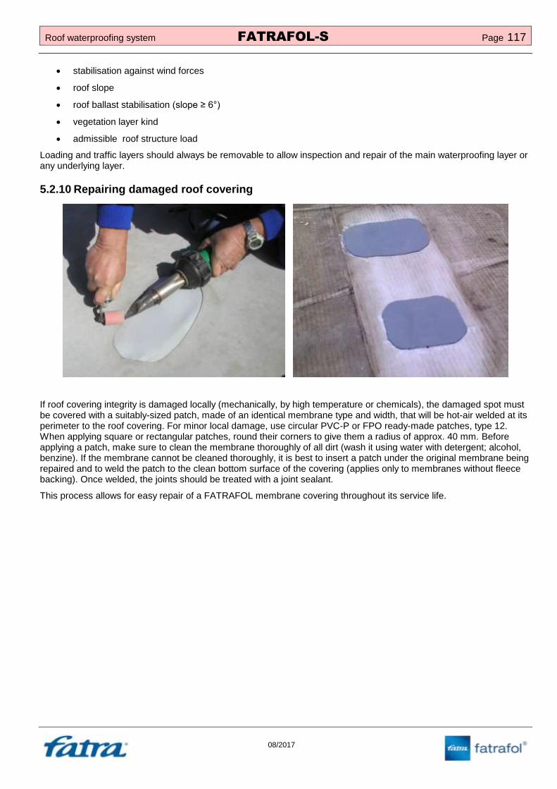
Roof waterproofing system FATRAFOL-S Page 117
08/2017
stabilisation against wind forces
roof slope
roof ballast stabilisation (slope ≥ 6°)
vegetation layer kind
admissible roof structure load
Loading and traffic layers should always be removable to allow inspection and repair of the main waterproofing layer or any underlying layer.
5.2.10 Repairing damaged roof covering
If roof covering integrity is damaged locally (mechanically, by high temperature or chemicals), the damaged spot must be covered with a suitably-sized patch, made of an identical membrane type and width, that will be hot-air welded at its perimeter to the roof covering. For minor local damage, use circular PVC-P or FPO ready-made patches, type 12. When applying square or rectangular patches, round their corners to give them a radius of approx. 40 mm. Before applying a patch, make sure to clean the membrane thoroughly of all dirt (wash it using water with detergent; alcohol, benzine). If the membrane cannot be cleaned thoroughly, it is best to insert a patch under the original membrane being repaired and to weld the patch to the clean bottom surface of the covering (applies only to membranes without fleece backing). Once welded, the joints should be treated with a joint sealant.
This process allows for easy repair of a FATRAFOL membrane covering throughout its service life.

Page 118 FATRAFOL-S Roof waterproofing system
08/2017
6 OCCUPATIONAL HEALTH & SAFETY, FIRE PREVENTION
6.1 Occupational health & safety at construction site
The essential Czech republic legal regulations that lay down the requirements for occupational health and safety
include Act 309/2006 Coll. (further conditions for occupational health and safety), Act 262/2006 Coll. (Labour Code as
amended), Government Regulation 101/2005 Coll. on detailed requirements for workplaces and work environments,
Government Regulation 591/2006 Coll. on essential requirements for occupational health and safety at construction
sites, Government Regulation 361/2006 Coll. on essential requirements for occupational health and safety at work
and Government Regulation 362/2005 Coll. on detailed requirements for occupational health and safety for works involving the risk of a fall from a height or into a depth.
The contractor’s general obligations regarding project preparation and implementation are laid down in Act 309/2006 Coll.
Detailed requirements for construction site safety, and safe operation and use of machines, equipment, devices and tools are laid down in Government Regulation 378/2001 Coll. Construction site specific requirements are given in Government Regulation 591/2006 Coll., including requirements related to the organisation of works and construction works (e.g. material storage and handling, groundwork, concreting, installation works etc).
Act 262/2006 Coll., Labour Code, applies to the provision of personal protective equipment (PPE). Detailed requirements for PPE are given in Government Regulation 495/2001 Coll.
6.2 Fire prevention
Act 133/1985 Coll. on fire prevention, is the essential framework for creating conditions that effectively protect human life, health and property from fire, and for providing first aid during natural disasters and emergencies.
The act is implemented through Decree 246/2001 Coll. on fire prevention, which defines basic terms related to fire safety.
Other regulations that lay down specific requirements for building fire safety include Act 23/2008 Coll. with regulation 268/2011 Coll. about technical regulation of building fire safety, Act 102/2001 Coll. and Act 59/1998 Coll. on general requirements for building product safety.
6.3 Installation-related safety risks
When installing FATRAFOL-S membranes, follow the above safety, sanitary and fire regulations, as most recently amended, regarding work at construction sites, in particular work at heights.
Electrical equipment (welding machines, drills etc) must be connected and operated in accordance with current regulations, in particular Government Regulation 378/2001 Coll. Connection cables for handheld electrical equipment and construction equipment must be maintained in accordance with manufacturer’s instructions and inspected at regular intervals.

Roof waterproofing system FATRAFOL-S Page 119
08/2017
Take extra care when handling adhesives and other materials containing solvents, thinners etc. These products are class I flammables and their handling requires adherence to common safety precautions.
A written system of OHS risk prevention is required for most new construction projects. Such documentation is usually part of site takeover documents. Compliance with safety precautions is reviewed by site supervisors and by occupational safety coordinators at larger construction sites.

Page 120 FATRAFOL-S Roof waterproofing system
08/2017
TEMPLATE: RISK FACTORS AND MITIGATION MEASURES
SITE:
CONTRACTOR Fatra, a.s., Napajedla, Třída Tomáše Bati 1541, 763 61
WORK TYPE: Roof deck membrane covering
Place Hazard type Risk Precautions
Fatr
a, a.s
., N
apaje
dla
Risk of falling from a height or into a depth
1
Protective structures must be erected at the site (scaffolding, protective barriers, fall arrests etc, Decree 362/2005 Coll.). Employees must have personal protective equipment against falls from a height according to EN 358 and EN 361. Employees must be trained in OHS and have a current medical examination.
Damage to health or risk to life due to inappropriate storage and handling of materials
1
Materials must be stored and placed in such a manner to ensure their stability and avoid damage to employee health; do not exceed the permissible load of the substrate. An employee must not handle loads heavier than 50 kg.
Tripping, sprains, hitting obstructions and penetrations at the site or getting caught by them
1 Remove obstructions, keep routes safe and clear, create transport routes for employees.
Slipping, stepping on a stair edge with the foot in an unstable position upon the stair
1 Keep an anti-slip surface on vertical routes, walk carefully on staircases, use prescribed safety footwear.
Knife cuts, sliding and/or cracking of
blade cuts on hands, legs and front part of the body
1
Take extra care when cutting and splitting material. Use OEM cutting tools and replaceable knife blades, use manufacturer-recommended cutting tools for the material, work with care and do not apply excessive force on the tools, use PPE – Kevlar gloves.
Eye injury caused by flying debris or chips (material cutting, concrete or metal drilling etc)
1 Follow safe working practices, make sure there are no chips and cracks on the tools, use suitable eye and face protection.
Employee being hit by a loose tool or its component (hammer, cutter, drill bit etc)
1 Follow proper working practices and use proper tools, fasten the tools to your belt or working platform, use required PPE (hard hat, goggles, gloves, footwear, work clothing).
Clothes or their loose parts getting caught in rotating equipment (typically a drill bit of an electric drill, grinding disc, fastener etc)
1 Wear suitable, closely fitting clothes and cap. Do not wear gloves close to rotating equipment. Concentrate on the work.
Irritation to airways and mucous membranes when handling solvents, thinners mineral wool
1
Follow safe working practices, wear breathing masks, protective clothing, cap and protective goggles. Make sure fine dust is removed from the workplace. Provide sufficient ventilation for interior works.
Operator injury by electric shock 1
Do not use any damaged power tools, keep connection cables, distribution boards and connection points in full working order and protect them from damage by construction works. Advise all employees of occupational safety rules – only persons familiar with the rules may use power tools. Provide the protection class required by the tool or equipment manufacturer.
Limb bruises caused by load handling (membrane rolls, palettes )
1 Use PPE for hand protection and work footwear with toe protection, take extra care when laying material on rigid support.

Roof waterproofing system FATRAFOL-S Page 121
08/2017
6.4 Roof safety during use
The durability of the entire roof deck depends on the durability of structural components with the shortest renewal or replacement interval. When a finished roof deck is handed over to the client, make sure to schedule inspections and, if necessary, renewal of selected roof components. If the roof is open to public use (parks, playgrounds, sports grounds etc), give consideration to the risk of intentional damage to or theft of roof deck structural parts or components and adopt suitable measures to minimise such risk.
Safe access to the roof deck must be provided in line with the intended use of the roof. Access to roofs open to traffic is usually described in project documentation. Access to other types of roofs must be provided to allow inspection, maintenance and repair of rooftop equipment. Roof access minimum openings are laid down in ČSN 73 1901:
walk through opening 600x1800 (roofs with traffic)
vertical access opening 600x1200 (roof without traffic)
horizontal access opening 600x600 (roof without traffic)
Roof decks must incorporate a fall arrest system to allow inspection, maintenance and repair of the traffic layer and all equipment placed on it. Under CSN 74 3305 – Safety railings, a safety railing may be used instead of a fall arrest system. The roof Instructions must include safety instructions regarding movement on the roof deck under various weather conditions. The Instructions should also contain a list of informed persons who are allowed access to the roof.
Roof walkways to individual devices must be made of anti-slip material. Also material used under walkways should resist to predicted traffic loads.
Lightning conductors placed on rooftop walkways must not cause an obstruction and safety passages must be built to cross them.
The roof deck perimeter must be so designed that roof deck structural parts and components or rooftop equipment cannot fall over the edge.

Page 122 FATRAFOL-S Roof waterproofing system
08/2017
7 INSPECTIONS AND ACCEPTANCE OF INSTALLED FATRAFOL-S SYSTEM
7.1 Quality inspection
As part of its production management system, Fatra, a.s., Napajedla, the manufacturer of waterproofing membranes, formulated and maintains the ‘Inspection Instructions for FATRAFOL Waterproofing Membranes’ that specifies general rules, responsibility for and methods of inspections of membrane coverings and of data processing.
1. The quality of the base structure must be checked before installation of a vapour control layer. The inspection should focus primarily on the structure completeness within the main field, detailing of penetrations and adjacent structures, adherence to process times, on whether the surface is planar and free of dirt, debris, puddles, ice and snow etc, on the required slope angle, completeness of rooftop equipment and connecting pipes, certificate of acceptance by the owner’s technical supervisor of documentation etc.
2. An inspection of the vapour control layer covers its quality in terms of technical parameters and quality of its installation in the roof structure. Check, the layer integrity, joints of individual sheets, the way the membrane is joined to perimeter, end and penetrating structures.
3. Inspect of thermal insulation: thickness and slope, gap width, gap filling if appropriate, the way the boards are fastened mechanically or bonded to the substrate, recesses around rainwater outlets, entrapped moisture, deformation of boards, surface strength after installation etc.
4. Before installing the main waterproofing layer, check the membrane quality and its conformity with the approved project documentation, in particular its type, thickness, straightness, undulating and other aspects that allow for visual inspection.
5. Check the following during the installation process: correct installation of the base and separation layer, if necessary, the position of plastic-coated metal profiles and their fastening and expansion gaps, Check placement of membrane sheets in accordance with the fixing plan, method of membrane sheet cutting, side and end overlaps, position of fixing lines, fastener type and quality, distance of fasteners from sheet edges and their required centre-to-centre distances in line, welding method, weld quality and geometry, details and detailing of rainwater outlets.
6. Each roof structure layer should be inspected and sign off to investor’s technical supervisor before covered by following layer.
7. These inspections are to be made by a contractor’s representative. Within a handover process, complete sections of the membrane covering are inspected, in accordance with contract terms and conditions, by the contractor’s engineer, construction site representative, the owner’s technical supervisor and other authorised persons as necessary. Details of the handover process are noted in the construction log or constitute a separate report.
8. The work handover and acceptance process is governed by current legislation, owner’s requirements, approved terms. In addition to other documents demonstrating the work quality, the handover documentation must also include the so-called ‘roof Instructions’ and an inspection and renewal schedule for selected structural parts of the roof. It is highly important to schedule inspections of rainwater outlets to ensure they are in full working order. (When drafting this part of documentation, reference may be made to Annex H to current CSN 73 1901:2011 – Designing of roofs – Basic provisions, Renewal and inspection schedule). A handover report must be prepared in connection with the work handover and acceptance, indicating all relevant matters. such as obvious defects, outstanding works, deadlines for corrective action.

Roof waterproofing system FATRAFOL-S Page 123
08/2017
7.2 Tightness tests
Several methods or a combination thereof are available to test the tightness of a membrane covering, or more precisely of the waterproofing layer of a completed part or of the entire roof. Mechanical, vacuum and submersion tests are preferred for the FATRAFOL-S system. Other methods detailed below are used only exceptionally and require appropriate equipment.
1. Mechanical test – use a testing needle to check all types of welds no earlier than 1 hour after welding. A seam testing needle used for this test is included in the welder’s essential kit .Tip of needle should be dull, never sharp. Drive the needle in the direction of the weld and apply gentle side pressure to seam, to easily detect any non-welded or separated points in the weld. This test should be performed before securing the welds with a joint sealant.
2. Vacuum test – based on EN 1593, this test checks randomly selected points of the waterproofing layer (T-joints, 3D details, valleys, rainwater outlets etc) using shaped bells of organic glass and a vacuum pump. The test is limited by the size of the testing bell (approx. 600 mm), which makes it costly and time consuming to test the entire length of all welds. A detection liquid (soap solution) is applied on the tested surface, a testing bell is attached and compressor is turned on to create under pressure in bell . If no bubbles appear on the tested surface during 30 seconds, the tested spot is tight.
3. Submersion test – this test can be done by following method specified by CSN 75 0905 - Water supply and sewerage tanks. Testing of water-tightness - may to some extent be used for this test. The use of this method is limited by roof deck specifications, in particular the permissible load of the load-bearing structure, maximum water level and the roof deck area. Typically, roof decks up to 100 m
2 in area are covered with a continuous
water layer while larger roofs are only partly covered, e.g. in valleys between roof planes or in individual tested sectors. The maximum water column height should be determined by a structural engineer, with consideration being given to dynamic load of the roof deck.

Page 124 FATRAFOL-S Roof waterproofing system
08/2017
4. Other methods – for example Impedance defectoscopy, spark test (high-frequency voltage), smoke test. These tests are less suited for roof deck inspections and require special measures to be conclusive.
All of the above tests must be agreed upon in advance with the site management and owner’s technical supervisor, and must be approved by the project documentation author. Also bear in mind that testing costs, e.g. for an immersion test, may run up to thousands of euros.
Technical documentation must be kept for all performed tests and a test report must be issued. Test reports for some tests are specified by standards while other tests allow for using an own test report. For some types of tests, the inspectors should be qualified in accordance with special regulations.

Roof waterproofing system FATRAFOL-S Page 125
08/2017
8 FITTER’S QUALIFICATIONS AND EQUIPMENT
8.1 Qualifications
Fitters installing the FATRAFOL-S waterproofing system must be trained in this work. Regular and special training for new contractors is provided by Fatra’s Insulation Studio and a ‘Certificate of qualifications for installation of FATRAFOL waterproofing membranes’ is issued after completion of a 2-day training course. The certificate is valid for 5 years. In accordance with its sustainable development programme, Fatra, a.s., Napajedla provides training courses in product innovations, advanced technologies and legislative changes. These training courses are an opportunity to share technical information and enhance contractors’ expertise.
The fitters’ supervisor should submit the above ‘Certificate of qualifications for installation of FATRAFOL waterproofing membranes’ at request. The certificate is a guarantee by Fatra, a.s. Napajedla, the FATRAFOL manufacturer, that the fitters received training and are qualified for the works indicated therein. Team members not holding this certificate may only do unskilled work.
This certificate is not a substitute for technical education (e.g. certificate of apprenticeship in insulation) and does not lead to obtaining a trade licence in the field of insulations.
8.2 Fitters’ equipment
8.2.1 Electrical equipment
Hot-air welding machine with 40 mm and 20 mm wide slot nozzle (recommended type: LEISTER TRIAC S or TRIAC PID, TRIAC AT, HERZ – Rion)
Hot-air mobile automatic welding machine (recommended type: LEISTER VARIMAT, HERZ – Laron etc)
Impact drill with set of drill bits for concrete and other materials
Water extractor
Vacuum pump and bells for vacuum tightness test
Cordless screwdriver
Angle grinder with metal cutting disc
Other electrical equipment and devices such as automatic fastening machines, sealing guns, PU adhesive applicators etc
Electrical extension cord

Page 126 FATRAFOL-S Roof waterproofing system
08/2017
8.2.2 Work tools
Tension meter
Levelling instrument
Folding ruler
Steel ruler
Thermometer
Greasy chalk
Carpenter’s pencil
Knife with hook
Scissors
Membrane cutting pad
Handheld rubber and Teflon rollers
Pressing roller (if membrane is bonded to substrate)
Tool for driving blind rivets (steel pipe Js 4÷5 mm, approximate length 150 mm)
Hammer
Rivet pliers
Sealant cartridge gun
Combination pliers
Joint testing needle
Puncher set
PE bottles with delivery tube
Steel cutter
Cleaning cloths
Flat and crosshead screwdrivers
Rubber spatulas for cleaning membrane surface
Hacksaw
Sponges for removing puddles
Hand metal shears
PE waste bags
Brass brush for cleaning slot nozzles
Broom
Spatulas for sealant
Dustpan

Roof waterproofing system FATRAFOL-S Page 127
08/2017
8.2.3 Essential hand tools – installation kit
Essential protective equipment:
Work clothing
Soft-soled shoes with a safety toe cap for summer/winter use
Protective gloves made of chrome tanned leather
Protective goggles or face shield
Knee guards
Cap with shield
Sun glasses with UV filter
Ear protectors
Dust mask (not necessary)

Page 128 FATRAFOL-S Roof waterproofing system
08/2017
9 NORMATIVE REFERENCES
Standard Czech title English title
CSN 73 0540-2 Tepelná ochrana budov - Část 2: Požadavky Thermal protection of buildings - Part 2: Requirements
CSN P 73 0606 Hydroizolace staveb - Povlakové hydroizolace - Základní ustanovení
Waterproofing of buildings - Continuous sheet water proofing - Basic provisions
CSN 73 1901 Navrhování střech - Základní ustanovení Designing of roofs - Basic provisions
CSN 73 3610 Navrhování klempířských konstrukcí Design of sheet metal constructions
CSN 74 3305 Ochranná zábradlí Protective railings
CSN 74 4505 Podlahy – Společná ustanovení Floors – Common Regulations
CSN 75 0905 Zkoušky vodotěsnosti vodárenských a kanalizačních nádrží
Water supply and sewerage tanks. Testing of water-tightness
EN 13956 Hydroizolační pásy a fólie - Plastové a pryžové pásy a fólie pro hydroizolaci střech - Definice a charakteristiky
Flexible sheet for waterproofing - Plastic and rubber sheets for roof waterproofing - Definitions and characteristics
EN 13984 Hydroizolační pásy a fólie - Plastové a pryžové parozábrany - Definice a charakteristiky
Flexible sheets for waterproofing - Plastic and rubber vapour control layers - Definitions and characteristics
EN 14783 Celoplošně podepřené plechové výrobky pro střešní krytiny a vnější a vnitřní obklady - Specifikace výrobku a požadavky
Fully supported metal sheet and strip for roofing, external cladding and internal lining - Product specification and requirements
EN 1593 Nedestruktivní zkoušení - Zkoušení těsnosti - Bublinková metoda
Non-destructive testing - Leak testing - Bubble emission techniques
CSN EN 1991-1-1 Eurokód 1: Zatížení konstrukcí - Část 1-1: Obecná zatížení - Objemové tíhy, vlastní tíha a užitná zatížení pozemních staveb
Eurocode 1: Actions on structures - Part 1-1: General actions - Densities, self-weight, imposed loads for buildings
CSN EN 1991-1-3 Eurokód 1: Zatížení konstrukcí - Část 1-3: Obecná zatížení - Zatížení sněhem
Eurocode 1: Actions on structures - Part 1-3: General actions - Snow loads
CSN EN 1991-1-4 Eurokód 1: Zatížení konstrukcí - Část 1-4: Obecná zatížení - Zatížení větrem
Eurocode 1: Actions on structures - Part 1-4: General actions - Wind loads
EN 358
Osobní ochranné prostředky pro pracovní polohování a prevenci pádů z výšky - Pásy pro pracovní polohování a zadržení a pracovní polohovací spojovací prostředky
Personal protective equipment for work positioning and prevention of falls from a height - Belts for work positioning and restraint and work positioning lanyards
EN 361 Osobní ochranné prostředky proti pádům z výšky - Zachycovací postroje
Personal protective equipment against falls from a height - Full body harnesses
EN ISO 14001 Systémy environmentálního managementu - Požadavky s návodem pro použití
Environmental management systems - Requirements with guidance for use
EN ISO 9001 Systémy managementu kvality - Požadavky Quality management systems - Requirements
ČSN 73 0202 Geometrická přesnost ve výstavbě-Základní ustanovení
Geometric accuracy in building. General requirement
ČSN EN ISO 6946.
Stavební prvky a stavební konstrukce - Tepelný odpor a součinitel prostupu tepla - Výpočtová metoda
Building components and building elements - Thermal resistance and thermal transmittance - Calculation method
ČSN EN 12056-3 Vnitřní kanalizace - Gravitační systémy - Část 3: Odvádění dešťových vod ze střech - Navrhování a výpočet
Gravity drainage systems inside buildings - Part 3: Roof drainage, layout and calculation
Roof waterproofing system FATRAFOL-S Page 129
08/2017
10 Typical roofing details
10.1 Overview of details
10.1.1 Joining FATRAFOL- mutually and with supplementary materials
Detail 201 S: Joining FATRAFOL membrane at overlaps without mechanical fastening and at crosswise joints
Detail 202 S : Joining adhered FATRAFOL at overlaps
Detail 203 S: Joining FATRAFOL membrane at overlaps when mechanically fixed
Detail 204 S: Joining FATRAFOL 807 membrane on long side
Detail 205 S: FATRAFOL 807 and 807/V membrane cross joint
Detail 206a S: Joining FATRAFOL 814 membrane when mechanically fastened
Detail 206b S: Joining FATRAFOL 814 membrane using adhered strip of FATRAFOL membrane
Detail 207 S: Joining FATRAFOL membrane with roof perimeter edging profiles
Detail 208 S: Joining FATRAFOL 807 and 807/V membrane with roof perimeter edging profiles
Detail 209 S: Joining FATRAFOL membrane with linear fixing components from plastic coated sheet metal profiles
Detail 210 S: FATRAFOL membrane – additional fastening
Detail 211 S: Additional insulation of internal corner by shaped piece
Detail 212 S: Additional insulation of external corner by shaped piece
Detail 213 S: Mechanical fastening of FATRAFOL membrane in center of sheet (with patch)
Detail 214 S: Maintenance walkways on roof cover
10.1.2 Ending roof covering on vertical surface
Detail 301 S: Ending FATRAFOL membrane on vertical surface
Detail 302 S: Ending FATRAFOL membrane on vertical surface
Detail 303 S: Ending FATRAFOL membrane on thermal insulated vertical surface
Detail 304 S: Ending FATRAFOL 814 membrane on vertical surface – metod 1
Detail 305 S: Ending FATRAFOL 814 membrane on vertical surface – metod 2
10.1.3 Transition of roofing membrane from vertical to horizontal position
Detail 401 S: Transition of FATRAFOL membrane from horizontal to vertical position at wall (parapet) corner - roof covering without thermal insulation
Detail 402 S: Transition of FATRAFOL membrane from horizontal to vertical position - roof with typical order of layers on trapezoidal sheet metal
Detail 403 S: Transition of FATRAFOL membrane from horizontal to vertical position - restoration of roof covering
Detail 404 S: Transition of FATRAFOL membrane from horizontal to vertical position - roof with typical order of layers
Detail 405 S: Transition of FATRAFOL membrane from horizontal to vertical position – roof covering with tiles installed on spacers
Detail 406 S: Transition of FATRAFOL from horizontal to vertical position – ballasted roof by pea gravel with typical order of layers
Detail 407 S: Transition of FATRAFOL membrane from horizontal to vertical position – inverse roof
Detail 408 S: Transition of FATRAFOL membrane from horizontal to vertical position – roof with vegetative layer
Detail 409 S: Connection of bituminous membrane with FATRAFOL membrane with added thermal insulation

Page 130 FATRAFOL-S Roof waterproofing system
08/2017
Detail 410 S: Transition of FATRAFOL membrane to vertical position – fastening of “L” profile to sandwich panel when FATRAFOL oriented paralel to parapet
10.1.4 Detailing of parapets and ending of roof covering at roof plane
Detail 501 S: Detailing of parapets with plastic coated sheet metal profiles
Detail 502 S: Detailing of parapets on sandwich panels
Detail 503 S: Ending FATRAFOL membrane with plastic coated sheet metal drip mould in roof plane
Detail 504 S: Ending FATRAFOL membrane with plastic coated sheet metal drip mould, ballasted layer secured by pea gravel stop profile
Detail 505 S: Ending FATRAFOL membrane with plastic coated flashing component
Detail 506 S: Ending FATRAFOL membrane with drip mould on wall (parapet) with system ETICS
Detail 507 S: Ending FATRAFOL membrane with plastic coated flashing component
Detail 508 S: Ending FATRAFOL membrane with plastic coated sheet metal drip mould
Detail 509 S: Patching plastic coated flashing components expansion gap
Detail 510 S: Fastening FATRAFOL membrane at parapet of 600 – 1200 mm height – metod 1
Detail 511 S: Fastening FATRAFOL membrane at parapet of 600 – 1200 mm height – metod 2
Detail 512 S: Fastening FATRAFOL membrane at parapet of 600 – 1200 mm height – metod 3
Detail 513 S: Fastening FATRAFOL membrane at parapet of 600 – 1200 mm height – metod 4
10.1.5 Gutters, rainwater outlets and penetrations
Detail 601 S: Detailing of thermal insulated rainwater gutter with FATRAFOL membrane
Detail 602 S: Detailing of existing rainwater gutter behind parapet with FATRAFOL membrane
Detail 604 S: Joining FATRAFOL membrane with doubled rainwater outlet
Detail 605 S: Joining FATRAFOL membrane with horizontal rainwater outlet
Detail 606 S: Detailing of railing pole with FATRAFOL membrane
Detail 607a S: Detailing of thermal insulated pipe penetration
Detail 607b S: Detailing of thermal insulated pipe penetration
Detail 608 S: Detailing of non-insulated pipe penetration
Detail 609 S: Vent outlet on thermal insulated roof
Detail 610 S: Vent outlet on thermal insulated roof with original roof composition
10.1.6 Expansion joints
Detail 701 S: Expansion joint in ballasted roof
Detail 702 S: Expansion joint in mechanically fastened roof, FATRAFOL oriented paralel to expansion joint
Detail 703 S: Expansion joint in mechanically fastened roof, FATRAFOL oriented across expansion joint
Detail 704 S: Expansion joint in adhered roof

Roof waterproofing system FATRAFOL-S Page 131
08/2017
10.2 Drawings of details
The following drawings show how standard details are finished. The method of fastening membranes to the substrate is only indicative in the cross sections. Fasteners and their layout must always be chosen in accordance with the above construction specifications.

NOTES: