strengthening of rc beams with large openings in … reinforced polymer (cfrp) strengthening of rc...
TRANSCRIPT
Abstract—To date, theoretical studies concerning the Carbon
Fiber Reinforced Polymer (CFRP) strengthening of RC beams with openings have been rather limited. In addition, various numerical analyses presented so far have effectively simulated the behaviour of solid beam strengthened by FRP material. In this paper, a two dimensional nonlinear finite element analysis is presented to validate against the laboratory test results of six RC beams. All beams had the same rectangular cross-section geometry and were loaded under four point bending. The crack pattern results of the finite element model show good agreement with the crack pattern of the experimental beams. The load midspan deflection curves of the finite element models exhibited a stiffer result compared to the experimental beams. The possible reason may be due to the perfect bond assumption used between the concrete and steel reinforcement.
Keywords—CFRP, large opening, RC beam, strengthening
I. INTRODUCTION PENINGS are usually found in floors due to staircase, elevators, ducts and pipes. Openings are provided
through the floor beams to facilitate the passage of utility pipes and service ducts. These service ducts are to accommodate essential services such as conduits, power supply, water and drainage pipes, ventilation system, air-conditioning and network system access or even for inspection purposes in beam structures. These arrangements of building services resulted in a significant reduction in headroom, minimize the storey height and results in major savings in material and construction cost especially in multi-storey buildings and tall building construction. [1].
However, the presence of opening in the web of a reinforced concrete beams resulted in many problems in the beam behavior including reduction in beam stiffness, excessive cracking and deflection and reduction in beam capacity. Furthermore, inclusion of openings leads to high stress concentration around the openings especially at the opening corners. The reduction of area in the total cross sectional dimension of a beam changes the simple beam behavior to a more complex one [2], [3].
S.C. Chin is presently a PhD student in Civil Engineering Department,
Universiti Teknologi PETRONAS, Malaysia (Corresponding author e-mail: [email protected]).
N. Shafiq is with Civil Engineering Department, Universiti Teknologi PETRONAS, Malaysia (e-mail: [email protected]).
M.F. Nuruddin is with Civil Engineering Department, Universiti Teknologi PETRONAS, Malaysia (e-mail: [email protected]).
Strengthening of beams with openings primarily depends on
the condition of building services either pre-planned or post-planned. In the case of pre-planned, the sizes and locations of openings are known in advance during the design stage. Thus, sufficient strength and serviceability of beams with opening can be ensured before construction. Although no specific guidelines or standards are provided in any of the major codes, the design engineer can extract the necessary information and guidelines reported in the literatures [1]. To restore the original structural capacity of beam due to openings, the available literatures [4], [5] presented the role of diagonal bars as corner reinforcement and inclined reinforcement for strengthening around the opening [6]. Steel reinforcement provided at the upper and lower chords and diagonal reinforcement placed around the opening are considered as internal strengthening.
For the case of post-planned, it involves drilling of openings in an existing structure. Problems may arise during the laying process of utility pipes and ducts. During the process, M&E engineers request to provide or re-locate the position of opening to simplify the arrangement of pipes and ducts which is not considered in the design. If openings are to be provided in existing beams especially in the shear zone, sufficient treatment and attention is needed to ensure the safety and serviceability of the structure. In general, shear failure of concrete structures is catastrophic due to the brittle nature and the fact of no advance warning prior to failure. Thus, in an existing beam, strengthening externally around the opening is crucial with the use of external reinforcing material, such as steel plates or by fiber reinforced polymer (FRP) materials.
The application of FRP as external reinforcement to strengthen concrete beams has received much attention from the research community. The most common type of FRP in the concrete industry is made with carbon, aramid or glass fibers. The FRPs are usually in the form of sheets, strips, wraps or laminates. These materials were applied by bonding it to the external surfaces of the beams with various configurations and layouts. The use of FRPs to repair and rehabilitate damaged steel and concrete structures has become increasingly attractive due to its well-known good mechanical properties, particularly with its high strength to weight ratio and low weight. Numerous experimental studies have shown that externally bonded FRP laminates could significantly increase a member’s stiffness and load carrying capacity, enhance flexural and shear capacities, providing confinement and ductility to compression structural members and also controls
Strengthening of RC Beams with Large Openings in Shear by CFRP Laminates: 2D
Nonlinear FE Analysis S.C. Chin, N. Shafiq and M.F. Nuruddin
O
International Journal of Civil and Environmental Engineering 6 2012
195
thusmbestrcoha
haexinlimMstropnoanexdocostrsqanva
Aexex
stuloef5020recobapr1.
bestratreex
he propagationsing FRPs as
members, varieen conducterengthening ontrary, the nave been rathe
The use of Cas received mxperimental nvestigations mited, particu
Madkour [8] rengthened repenings with on linear elasnalyzed the external strengomain to deteronfiguration. rengthening o
quare openingnalysis was calidated with t
In this invesATENA is usxperiment [14xperimental da
Experimentaudies carried
oaded with affective length00 mm. All b000 mm loneinforcement onsisted of twar for comprrovided and co
Fig.
Summary of eams consistrengthened bet distance 0.5emaining beamxcept that t
n of cracks [7external reinf
ious extensived in the arof solid be
numerical stuer limited. CFRP to stre
much attention studies [9]-[of RC beam
ularly with thinvestigated
einforced conca new numer
stic theory. Thefficiency of gthening techrmine the effe
Meanwhile, of reinforced g by externallyconducted usinthe experimenstigation, a nosed to valida]. Comparisonata are presen
II. EXPERIM
al results wereout [14]. Six
a four point h of 1800 mmbeams were 3ng. The effwas 280 mm
wo 12 mm ø bression. Shearonsisted of ø
1 Beam reinfor
f the tested beated of two eams with larg5d and d awms were similthe large sq
], [8]. Due to forcement for
ve experimenrea of FRP eams withoutudies to date
engthen RC bfrom researc
[12]. Howevm with openhe use of finon the non-crete beams wrical implemehe proposed applying CF
hnique in a ective and eco
Pimanmas concrete beamy installed FRng a finite el
ntal results. on-linear finitate the testens of the pred
nted.
MENTAL PROGR
e obtained frox reinforced c
loading conm, and distan300 mm highfective depth
m. The longitubar for tensior reinforceme6 mm c/c 300
rcement details
ams is listed isolid contro
ge square openway from thlar to the un-
quare openin
many advantr reinforced ctal researcheflexural and
t opening. Ofor this app
beams with opchers focusingver, the nunings are somnite element m
linear behaviwith rectangulentation of datheoretical apRP laminates
three dimeonomic strengt
[13] studiems with circu
RP rods. A nulement progra
te element pred beams frodicted results w
RAM om the experconcrete beamnfiguration w
nce between loh, 120 mm wih, d to theudinal reinfor
on and two 10ent was suff0 mm, as seen
(Unit:mm)
in TABLE I. Tol beams, twnings in shear
he support; a-strengthened ngs in shear
BBB2B3B4B5B6
tages of concrete es have d shear On the lication
penings g on the merical mewhat method. iour of lar web amage–pproach s as an ensional thening ed the ular and merical am and
rogram, om the with the
rimental ms were with an oads of ide and e main rcement 0 mm ø ficiently n in Fig.
The RC wo un-r region and the beams,
r were
stropco
thelammm
elepre
eleelaknrancoin MoThstrmacoof ascusecostropoc
Beam Shap1 Contr2 Contr3 Squa4 Squa5 Squa6 Squa
rengthened bypening was nfiguration w
e large squareminates with am were used.
Fig
III. NO
In this study,ement packaedictions are c
A. Material MFor the con
ement packagastic constantnown as equivnge of the mpression. Fo
compressionodel Code 90
he elastic limrength is reachaximum concrmpression is l
f concrete sofcending-desceed. The slopncrete modulu
ress-strain curpening law ancur when the
TABEAM
Op
pe Lorol Nrol N
are 0are are 0are
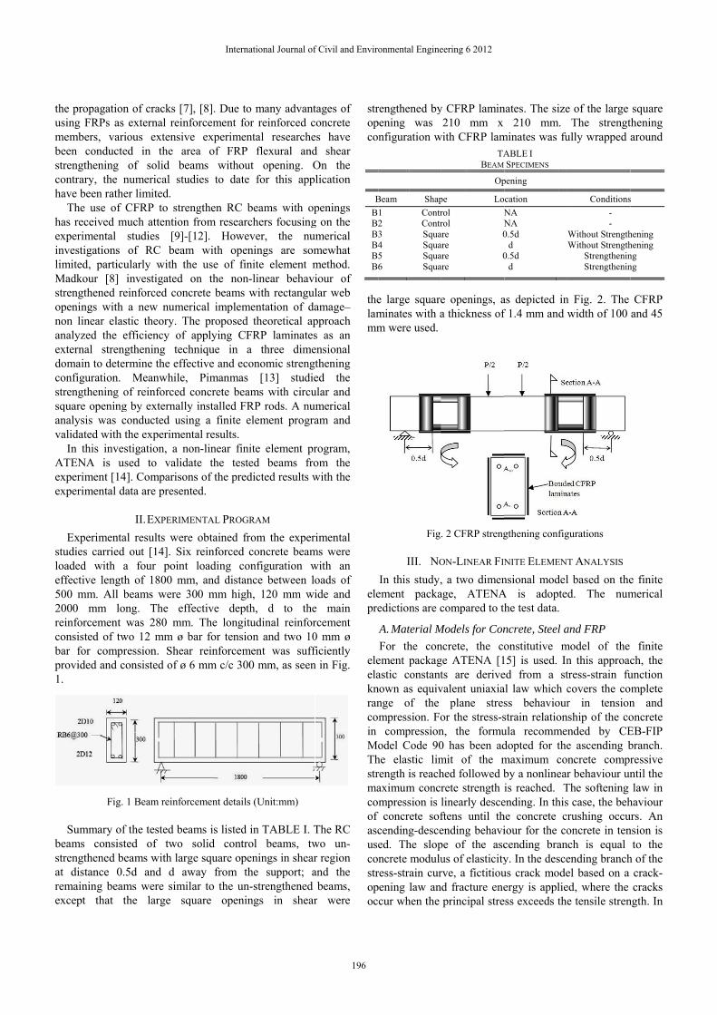
y CFRP lamin210 mm x
with CFRP lam
e openings, aa thickness of
. 2 CFRP streng
ON-LINEAR FIN
, a two dimenage, ATENAcompared to th
Models for Conncrete, the coge ATENA [1ts are derivevalent uniaxia
plane stresor the stress-sn, the formu0 has been admit of the mhed followed brete strength ilinearly desceftens until thending behavipe of the ascus of elasticityrve, a fictitioud fracture eneprincipal stre
ABLE I SPECIMENS
pening
cation NA NA 0.5d
d 0.5d
d
nates. The size210 mm.
minates was fu
as depicted inf 1.4 mm and w
gthening config
NITE ELEMEN
nsional modelA is adoptehe test data.
ncrete, Steel aonstitutive m
15] is used. Ined from a stal law which css behaviourstrain relationula recommedopted for themaximum coby a nonlinearis reached. T
ending. In thishe concrete ciour for the cocending brany. In the desceus crack modeergy is applie
ess exceeds the
Conditions- -
Without StrengthWithout Strength
StrengtheninStrengthenin
e of the large The strengt
ully wrapped
n Fig. 2. The width of 100
gurations
T ANALYSIS l based on thed. The num
and FRP model of the n this approactress-strain fucovers the cor in tension
nship of the conded by CEe ascending bncrete comprr behaviour un
The softening s case, the behrushing occuoncrete in ten
nch is equal ending branchel based on a ed, where the e tensile stren
s
hening hening ng ng
square thening around
CFRP and 45
e finite merical
finite ch, the unction omplete n and oncrete EB-FIP branch. ressive ntil the law in
haviour urs. An nsion is
to the h of the
crack-cracks
ngth. In
International Journal of Civil and Environmental Engineering 6 2012
196
this study, rotated crack model is adopted based on the smeared crack approach. Poisson’s ratio for concrete was assumed to be 0.2. Fig. 3 shows the uniaxial stress strain law for concrete.
Fig. 3 Uniaxial stress strain law for concrete
The steel is represented by multi-linear law which consists
of four lines as shown in Fig. 4. This law allows a linear modelling all four stages of steel behaviour: elastic state, yield plateau, hardening and fracture. The stress and strain of the steel reinforcement were measured in the experimental study. These values were used in the FEM model. A Poisson’s ratio of 0.3 was used for steel reinforcement. The bond between steel reinforcement and concrete was assumed as a perfect bond. A linear elastic orthotropic constitutive relation is assumed for the FRP composites. A rupture point on the stress strain relationship for the fiber direction defines the ultimate stress and strain of the FRP.
Fig. 4 Multi-linear stress strain law for reinforcement
B. FRP/Concrete Interface A bond slip model developed by Lu et al. [16] shown in
Fig. 5 is adopted. This bond slip model is considered as an accurate bond slip model that can be incorporated into finite element analysis [17]-[20]. The mechanical behaviour of the FRP/concrete interface is modeled as a relationship between the local shear stress, τ and relative displacement, s between the CFRP laminate and the concrete. The τ –s relationship is given by [17]
τ = τmax / o if s o (1)
τ = τmax exp[-α (s / o -1)] if s o (2) The maximum bond strength τmax and the corresponding slip
o are governed by the tensile strength of the concrete ft and a width ratio parameter βw as follows:
τmax = 1.5βwft (3)
o = 0.0195βwft (4)
The parameter βw is defined in terms of the CFRP laminate
width bf and the width of the beam bc as follows:
βw =2.25 – bf/bc
1.25 + bf/bc (5)
The area under the τ –s curve indicates the interfacial
fracture energy Gf which corresponds to the energy per unit bond area required for complete debonding; which is calculated as follows:
Gf = 0.308β2
w t (6) The difference in relative displacement between the
concrete and CFRP laminate represents the slip at the interface. The interface elements are considered to act only in the directions parallel to the main fiber reinforcements.
Fig. 5 Bond slip model
International Journal of Civil and Environmental Engineering 6 2012
197
C. Geometrical Modeling To represent the concrete, SBETA material model for two
dimensional plane stress elements was used. The tensile behaviour of concrete is modelled by nonlinear fracture mechanics combined with the crack band method, in which the smeared crack concept is adopted. The steel reinforcement, stirrups and CFRP laminates were modelled by a single straight line in a discrete manner by bar reinforcement elements. Full bond is assumed between the steel reinforcement and the surrounding concrete. The bond slip relation of CFRP and concrete was defined in bond for reinforcement material and assigned in the properties of discrete reinforcement bar of CFRP.
D. Nonlinear Solution In this study, a displacement-controlled incremental loading
method was adopted with an iterative solution procedure based on the Newton-Raphson method was employed.
IV. NUMERICAL RESULTS AND DISCUSSION The results presented in the following sections are given in
terms of load versus mid-span deflection curve relationships and crack patterns.
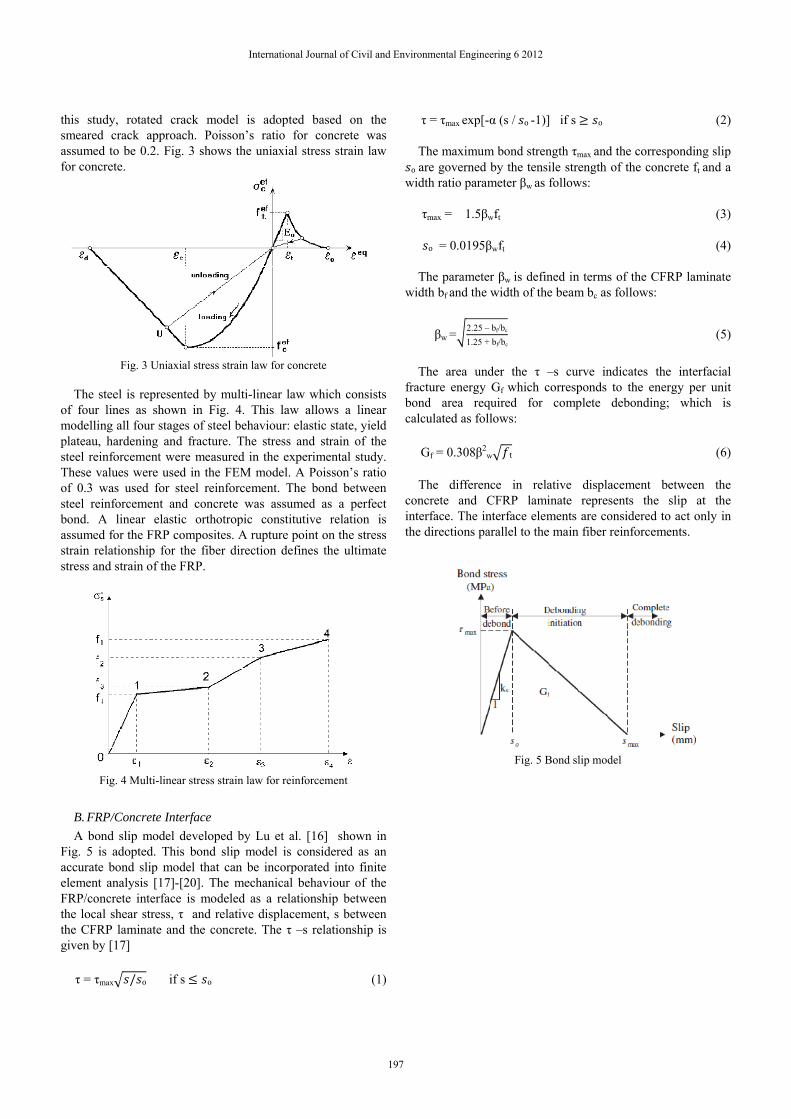
A. Load Deflection Curves The load deflection curves obtained for control beams, un-
strengthened and strengthened beams with large square openings in shear region are illustrated in Fig. 6.
Fig. 6a depicts the load deflection curves of control beams, B1 and B2 from experiments and FEM analysis. The control beams were solid beams without any openings. Similar trend of load deflection curves was observed between FEM and experimental results for the control beam. The FEM analysis predicts the beam to be stiffer and stronger. The possible cause for the difference in stiffness between the control beam in the experiment and the finite element analysis is due to the assumed perfect bond between concrete and steel reinforcement.
For the un-strengthened beams with large square openings in shear region at distance 0.5d and d away from the support, B3 and B4 which are shown in Fig. 6b, the results of both FEM models are close to identical, both demonstrated a stiffer trend than the experimental results. After the cracks started to appear, the perfect bond models increasingly overestimate the stiffness of the beam. Similar as in the control beams, the possible reason may be due to the assumed perfect bond condition between concrete and steel reinforcement.
The load deflection curves of the strengthened beams with CFRP fully wrapped around the large square openings in shear region at distance 0.5d and d away from the support, B5 and B6 are illustrated in Fig. 6c. After incorporating the bond slip model which defined in the discrete reinforcement properties of CFRP, almost similar trend was obtained between both FEM models compared to their respective experimental results. At early stage before initial crack, it was observed that the stiffness of beam B6 in finite element model are closely matching to the stiffness of experimental beam. Likewise, the second point of cracking at 1 mm deflection, a slight drop was
observed in all FEM and experimental curves. In the range of yielding of reinforcement to failure, the load deflection curves of both FEM models were comparable with the load deflection curves of both experimental results.
Fig. 6 Load deflection curves of beams, obtained by experiment and
finite element method
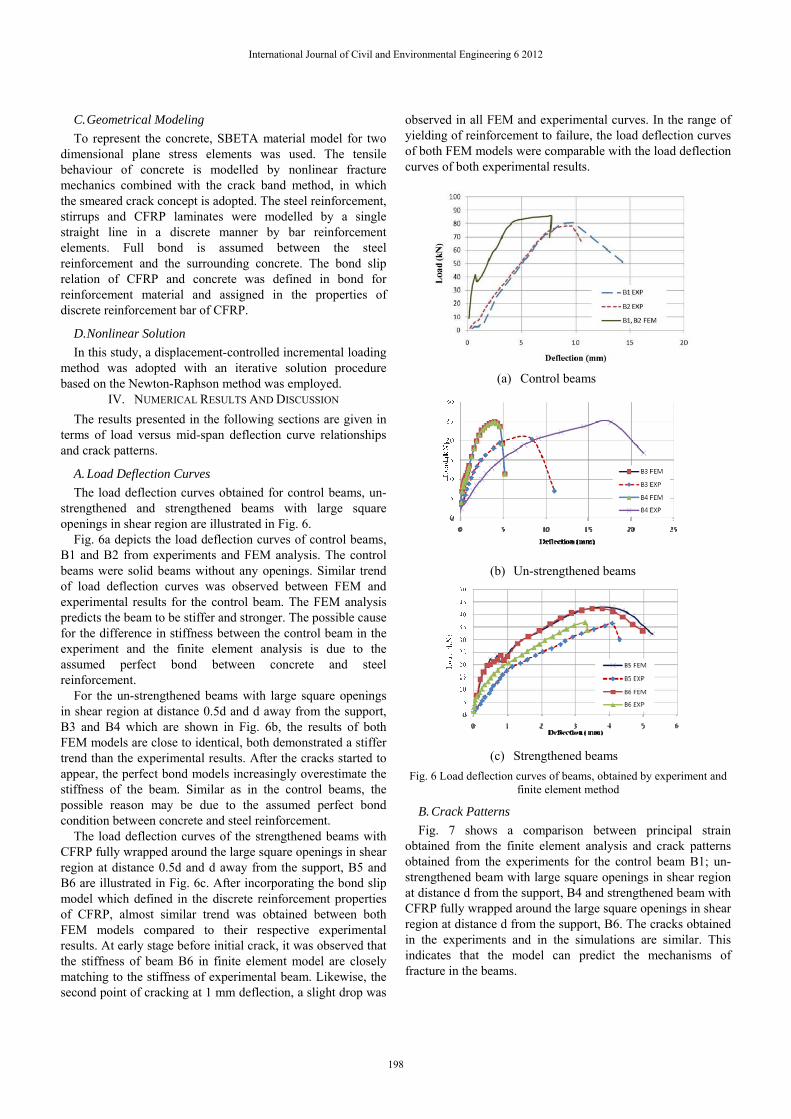
B. Crack Patterns Fig. 7 shows a comparison between principal strain
obtained from the finite element analysis and crack patterns obtained from the experiments for the control beam B1; un-strengthened beam with large square openings in shear region at distance d from the support, B4 and strengthened beam with CFRP fully wrapped around the large square openings in shear region at distance d from the support, B6. The cracks obtained in the experiments and in the simulations are similar. This indicates that the model can predict the mechanisms of fracture in the beams.
(a) Control beams
(b) Un-strengthened beams
(c) Strengthened beams
International Journal of Civil and Environmental Engineering 6 2012
198
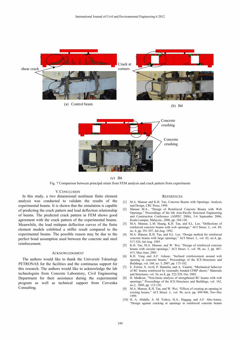
Fig. 7 Comparison between principal strain from FEM analysis and crack pattern from experiments
V. CONCLUSION
In this study, a two dimensional nonlinear finite element analysis was conducted to validate the results of the experimental beams. It is shown that the simulation is capable of predicting the crack pattern and load deflection relationship of beams. The predicted crack pattern in FEM shows good agreement with the crack pattern of the experimental beams. Meanwhile, the load midspan deflection curves of the finite element models exhibited a stiffer result compared to the experimental beams. The possible reason may be due to the perfect bond assumption used between the concrete and steel reinforcement.
ACKNOWLEDGMENT The authors would like to thank the Universiti Teknologi
PETRONAS for the facilities and the continuous support for this research. The authors would like to acknowledge the lab technologists from Concrete Laboratory, Civil Engineering Department for their assistance during the experimental program as well as technical support from Cervenka Consulting.
REFERENCES [1] M.A. Mansur and K.H. Tan, Concrete Beams with Openings: Analysis
and Design, CRC Press, 1999. [2] Mansur M.A., “Design of Reinforced Concrete Beams with Web
Openings,” Proceedings of the 6th Asia-Pacific Structural Engineering and Construction Conference (ASPEC 2006), 5-6 September 2006, Kuala Lumpur, Malaysia., 2006, pp. 104-120.
[3] M.A. Mansur, L.M. Huang, K.H. Tan, and S.L. Lee, “Deflections of reinforced concrete beams with web openings,” ACI Struct. J., vol. 89, no. 4, pp. 391-397, Jul-Aug. 1992.
[4] M.A. Mansur, K.H. Tan, and S.L. Lee, “Design method for reinforced concrete beams with large openings,” ACI Struct. J., vol. 82, no.4, pp. 517-524, Jul-Aug. 1985.
[5] K.H. Tan, M.A. Mansur, and W. Wei, “Design of reinforced concrete beams with circular openings,” ACI Struct. J., vol. 98, no. 3, pp. 407-415, May-June, 2001
[6] K.H. Yang and A.F. Ashour, “Inclined reinforcement around web opening in concrete beams,” Proceedings of the ICE-Structures and Buildings, vol. 160, no. 3, 2007, pp. 173-182.
[7] E. Ferrier, S. Avril, P. Hamelin, and A. Vautrin, “Mechanical behavior of RC beams reinforced by externally bonded CFRP sheets,” Materials and Structures, vol. 36, no.8, pp. 522-529, Oct. 2003.
[8] H. Madkour, “Non-linear analysis of strengthened RC beams with web openings,” Proceedings of the ICE-Structures and Buildings, vol. 162, no.2, 2009, pp. 115-128.
[9] M.A. Mansur, K.H. Tan, and W. Wei, “Effects of creating an opening in existing beams,” ACI Struct. J., vol. 96, no.6, pp. 899-906, Nov-Dec 1999.
[10] H. A. Abdalla, A. M. Torkey, H.A., Haggag, and A.F. Abu-Amira, “Design against cracking at openings in reinforced concrete beams
(a) Control beam
shear crack Crack at corners
(b) B4
Concrete crushing
Concrete crushing
(c) B6
International Journal of Civil and Environmental Engineering 6 2012
199
strengthened with composite sheets”. J Compos Struct., vol. 60, no. 2, pp. 197-204, May 2003.
[11] S.M. Allam, “Strengthening of rc beams with large openings in the shear zone”. J Engr, Alexandria, vol. 44, no. 1, pp. 59-78. 2005
[12] T. El Maaddawy and S. Sherif, “FRP composites for shear strengthening of reinforced concrete deep beams with openings”. J Compos Struct., vol. 89, no. 1, pp. 60-69, Jun 2009.
[13] A. Pimanmas, “Strengthening R/C beams with opening by externally installed FRP rods: behavior and analysis,” J Compos. Struct., vol. 92, no. 8, pp. 1957-1976, Jul. 2010.
[14] S.C. Chin, N. Shafiq and M.F. Nuruddin, “Strengthening of RC beams with large openings in shear by CFRP laminates: Test results,” International Conference on Civil, Offshore and Environmental Engineering, 12-14th June, Kuala Lumpur, Malaysia, 2012, (Submitted).
[15] V. Cervenka, L. Jendele, and J. Cervenka, “ATENA Program Documentation Part 1 Theory,” Cervenka Consulting Ltd, Prague. 2010.
[16] X.Z. Lu, J.G. Teng, L.P. Ye, and J.J. Jiang, “Bond – slip models for FRP sheets / plates bonded to concrete,” Engineering Structures, vol. 27, no. 6, pp. 920-937, Apr. 2005.
[17] R. Kotynia, H.A. Baky, K.W. Neale, M. Asce, and U.A. Ebead, “Flexural strengthening of rc beams with externally bonded CFRP systems :test results and 3d nonlinear FE analysis,” J. Compos. Constr.,vol. 12, no.2, pp. 190-201, Mac-Apr. 2008.
[18] Y.T. Obaidat, S. Heyden and O. Dahlblom, “The effect of CFRP and CFRP/concrete interface models when modelling retrofitted RC beams with FEM”, J Compos. Struct. vol. 92, no. 6, pp. 1391-1398, May 2010.
[19] A., P. Godat, Labossière, and K. W. Neale., “Numerical investigation of the parameters influencing the behaviour of FRP shear-strengthened beams”. Constr. and Build. Mat.,2011. In Press
[20] A. Godat, K.W. Neale, and P. Labossière, “Towards modelling FRP shear-strengthened reinforced concrete beams,” Proceedings of the 8th International Symposium on Fiber Reinforced Polymer Reinforcement for Concrete Structures", University of Patras, Patras, 2007.
International Journal of Civil and Environmental Engineering 6 2012
200