strengthening of historical construction by using steel
TRANSCRIPT
Structural Analysis of Historical Constructions - Modena, Lourenço & Roca (eds) © 2005 Taylor & Francis Group, London, ISBN 04 1536 379 9
Strengthening of historical construction by using steel bracing inserted into brick walls
M.Y. Minch, 1. Szolomicki, P. Berkowski & G. Dmochowski Wroclaw University ofTechnology, Wroclal1\ Po/and
ABSTRACT: In the presented paper authors show the way of strengthening construction ofhistorical Cisterian cloister using steel bracing inserted into brick bearing walIs. Endurance of bricks and mortars from which analysed erected walI was made is very smalI, therefore resulted necessity of checking endurance of connection of steel rod - joint-wall. Investigations of endurance of such connections were executed in order to get certainty of proper strengthening of construction.
INTRODUCTION
The Monastery in Lubiil.z is one of the most important and valuable monuments of Lower Silesia and its historical heritage is welI known not only in Poland. Today, the complex of Palace and Monastery is subjected to various restoration operations in which take the lead constructional works, strengthening and stiffening system of load-bearing building walIs.
The complex ofPalace and Monastery is located in Lubiil.z upon the Odra river, near the most important communication route north-south, 55 km away from Wrodaw - the capital of Lower Silesia. The complex is a part of a former Monastery of Cistercians. Historical beginnings of Cistercians' settlements in Lubiil.z date onto the first half of the XII century. The present complex of Palace and Monastery, together with the Church of Saint Mary the Virgin, were built in the years 1681- 1739. In that time the Monastery lived a period of economical and cultural development. AdditionalIy, it changed into brewery, hospital and many different industrial buildings. The new Abbot's Palace, the Monastery and the Church buildings which connects alI the buildings, create a huge complex belonging to the largest of this type in the central Europe. Its cubature carries out over 330 thousand m3 , length of western façade 223 m and width defined as length ofnorth wing oftheAbbot's Palace is 118m.
Secularisation of the abbey occurred in the year 1810. Monastic buildings were changed into hospital and church were turned into arsenal. From the year 1823 monastic buildings were adopted for mental hospital , while other buildings as welI as the Abbot's Palace became a property of the National Stud for
Horses. In that time many different valuable sculptures, coins, pieces of furniture, musical instruments etc. were taken away from the Monastery. During the II World War in the complex ofMonastery existed a military materiaIs factory served by International Camp of Compulsory Work. In the years 1945- 1948 a hospital for Soviet army was organised in the Monastery. In the spring of the year 1989 the Foundation "Lubiil.z" was founded, which main aim was reparation and adaptation of complex buildings, as welI as restoration of its former usable magnificence. Decoration of complex interior was baroque. Worthy of notice are richly decorated: the Prince 's HalI (28.5m x 14.8 m x 13.4m), the Abbot's dinning room (30.0 m x 13.0 m x 10 m) and a library (25.3 m x 10.7 m x 11.9 m).
In the eighties there was executed a reinforcement of Palace's load-bearing walIs system by means of conventional solutions of steel bracing. Lack of financiaI resources caused that temporary bracing protections were executed in monastic part, instalIing bracing with steel shape and rods 1.50 m above floors leveIs of each storey and anchoring bracings in cross steel beams fixed into window openings. That reinforcement, in accordance with conservatory recommendations, should to be removed and place on floors leveIs. AdditionalIy, there was not a conservatory agreement for anchoring of steel brace in historical buildings ' façade. It was a reason of proposing a reinforcement ofload-bearing walIs by means of steel bracings which were anchored by sticking. The welI-known technical realization of steel sticking in almost homogeneous materiaIs, such as steel insertion in orogene, reinforcement concrete etc. was decided to be transferred to masonry structures according to proposal of Minch et aI. (2000).
795
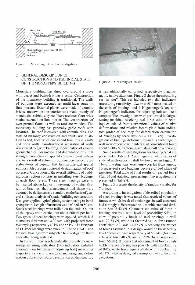
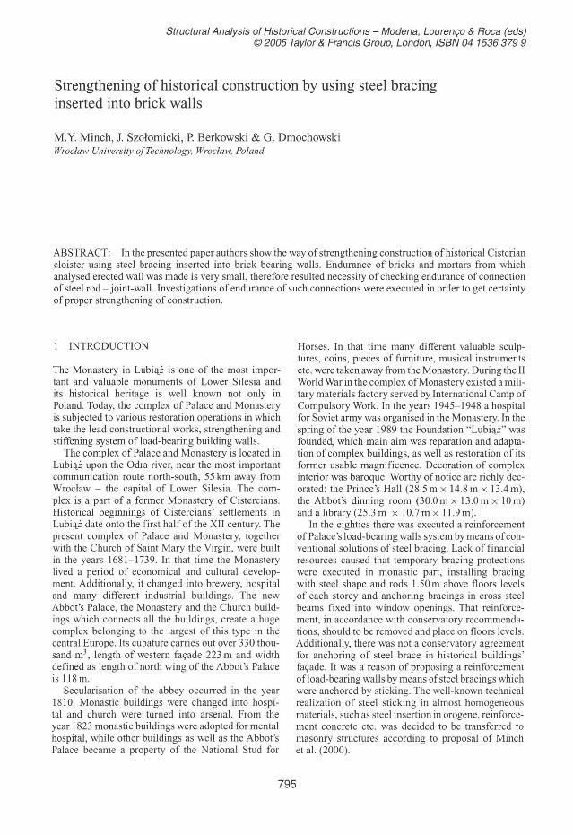
Figure 1. Measuring set used in investigations.
2 GENERAL DESCRIPTION OF CONSTRUCTION AND TECHNICAL STATE OF THE MONASTERY BUILDING
Monastery building has three over-ground storeys with garret and beneath it has a cellar. Construction of the monastery bui lding is traditional. The walls of building were executed as multi-Iayer ones on lime mortars. ExternaI planes were made of ceramic bricks, meanwhile the interior was made mainly of stones, also rubble, c1ay etc. There are inter-floor brick vaults executed on lime morta r. The constructions of over-ground floors as well as roof are wooden. The monastery building has generally gable roofs with lucarnes. The roof is covered with ceramic tiles. The state of masonry construction and vaults was qualified as bad, beca use of cracks and fractures in vaults and brick walls. Constructional separation of walls was caused by age ofbuilding, modi fica tion of ground geomechanical parameters and degradation of initial strength parameters of applied constructional materiais. As a result of action of roof counter-ties occurred dislocations of coping, that has insufficient spatial stiffness. Also a constructional destabil ization of roof occurred. Conception ofthe overall stiffening ofbui lding construction consists in install ing steel bracings at each floor leveis. Those steel bracings were to be inserted above key or in keystone of vaults. System of bracings, their arrangement and shape were assumed by designers as a standard on the basis of general stiffness analysis of spatial building construction. Designer applied typical gluing system using to bond epoxy resin. Length ofinsertion was defined on 80 cm. Stuck steel bracings were milled on the ends. Output of the epoxy resin carried out about 800 ml per hole. Two types of steel bracings were applied, which had diameters </!24 mm and </!30 mm with projected force to carrying respectively40 kN and 55 kN. The first part of Ii steel bracings were stuck in June of 1994. Then ten steel bracings were subjected to investigation three days after being installed.
In Figure I there is schematically presented a measuring set using indicators (two indicators installed alternately on two sides of adjusting bolt) measuring respectively slide ofbracings in anchorage and deformation of bracings. Before rea lisation on the structure
Figure 2. Measuring set " in situ".
it was additionally calibrated, respectively dynamometric in investigations, Figure 2 shows the measuring set " in situ". This set included two dial indicators (measuring sensitivity - 6.J1.- = ± I 0- 3 mm) located on the ends of bracings and 4 Hugenberger's key and Hugenberger's indicator, fo r adjusting bolt and steel samples. The investigations were performed in fatigue testing machine, receiving real force value in bracings calculated from conventional values of relative deformations and rei ative forces yield from indicators (order of accuracy fo r deformation calculation of brac ings by force was 6. v = ± I 0- 1 kN). Investigations ofbracings deformations and its anchorage in wall were executed with interval of conventional force about 5- 10 kN, tightening adjusting bolt on a bracing.
Some results of investigations for bracing No 4 are presented in Tables 1,2 and Figure 3, while values of si ide of anchorages in shift by force are in Figure 4. Three investigations were unsuccessful from among l O measured steel bracings because of bad place of insertion. Total table of f inal results of reached force (Tab. 3) and statistical processing of investigations are presented in Table 4.
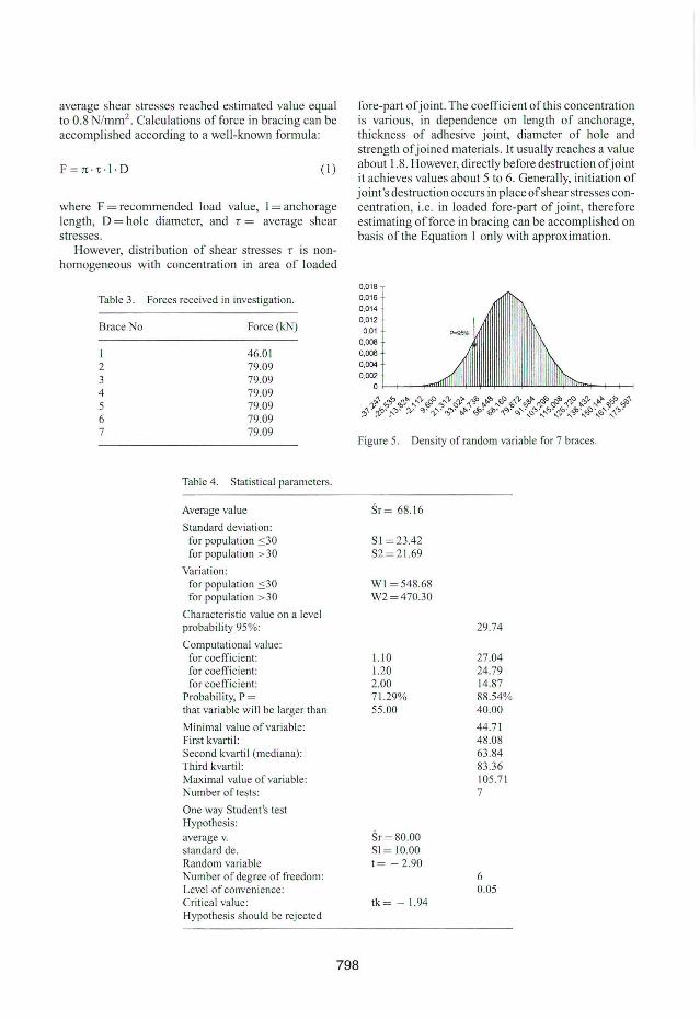
Figure 5 presents the density of random variable for 7 braces.
According to investigations of described population of steel bracings it was noted that received values of forces at which break of anchorages in wall occurred, had strongly differentiated values with standard deviation S = 23.42 kN. Characteristic value of force in bracing, received with levei of probabil ity 95%, in view of possibil ity break of steel bracings in wall was 29.74kN, while its factored value, for assumed coefficient 2.0, was 14.87 kN. Receiving the values of forces assumed in a design would be burdened by levei of convenience respectively of88.54% (for characteristic fo rce 40 kN) and 7 1.29% (for characteristic force 55 kN). It means that obtainment offorce equals 40 kN in steel bracing was possible with a probability of 89%, while force equals 55 kN with a probabil ity of 71 %, what in designed assumption was difficult to execution.
796
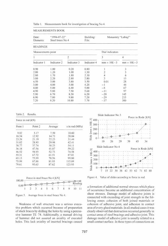
Table I. Measurements book for investigation of bracing No 4.
MEASUREMENTSBOOK
Date: "1994-07 -22" Elements: Steel brace No 4
READf'.IGS
Measurements point
2
Indicator 1 Indicator 2 Indicator 3
0.90 1.00 0.20 2.00 1.20 1.00 2.80 1.70 1.80 3.80 2.20 2.80 4.50 3.00 3.80 3.00 4.00 5.00 4.00 5.00 6.40 4.90 5.80 7.50 5.90 6.70 8.50 6.90 7.80 9.80 7.20 8.20 10.80
Table 2. Results.
Force in rod (kN)
Point I Point 2 Average s in rod (MPa)
9.82 5.17 7.50 10.60 16.54 12.92 14.73 20.84 23.26 21.19 22.23 31.44 31.02 28.95 29.98 42.41 38.77 37.74 38.25 54.11 36.18 47.56 41.87 59.22 46.52 58.93 52.73 74.58 55.31 67.72 61.51 87.0 1 65.13 75.99 70.56 99.80 75.99 87.88 81.93 115.89 79.61 95.63 87.62 123 .93
Force in steel brace No 4 [kN] 100,00
~g 0,00 Y==rc=='iI'---'f--+---j--t--t--1--t---1 I 2 3 4 5 6 7 8 9 10 11
Figure 3. Average force in steel brace No 4.
Weakness of wall structure was a serious executive problem which occurred because of preparation ofstuck braces by drilling the holes by using a percussive hammer TE- 74. Additionally, a manual driving of hammer did not assured an axiality of executed holes. This lack axiality of inserted bracings caused
Building: Monastery " Lubi'li" File:
Dial indicators
3 4
Indicator 4 mm x IOE-3 mm x IOE-3
0.80 1.50 2.30 2.80 3.50 4.20 5.00 5.60 6.20 7.20 7.70
I 3 2 5 4 6 3 15 0.01 28
-I 44 -8 67 -11 97 -20 145 -29 215 -37 300
Slide Indicator No 3
'" 400 ) . . . ... . . . . . . .. . F",~' "R~d' [kN! ~300 '~': >< • I , I , I
E200 -~--, E """ ~IOO ----,---- . ----,-- - - --,----. Q) " '"
'2 O "'" üi 19 26 29 39 45 34 '
Figure 4. Value of slides according to force in rodo
a formation of additional normal stresses which place of occurrence become an additional concentration of shear stresses. Damage model of adhesive joints is connected with exceeding of joint strength in the following zones: cohesion of both joined materiais or cohesion of adhesive joint, and adhesion in contact area of every glued materiais. In ali studied cases it was clearly observed that destruction occurred generally in contact areas of steel bracings and adhesive joint. This damage model of adhesive joint is usually related to a small contact surface. In these types of connections an
797
average shear stresses reached estimated value equaI to 0.8 N/mm2
. Calculations of force in bracing can be accomplished according to a well -known formula:
F=n·'t· I ·D (1)
where F = recommended Ioad value, 1 = anchorage Iength, O = hole diameter, and r = average shear stresses.
However, distribution of shear stresses r is nonhomogeneous with concentration in area of Ioaded
Table 3. Forces received in investigation.
Brace No Force (kN)
I 46.0 1 2 79.09 3 79.09 4 79.09 5 79.09 6 79.09 7 79.09
Table 4. Statistical parameters.
Average value
Standard deviation : for population ~30 for population > 30
Variation : for population ~30
for population > 30
Characteristic va lue on a leveI probability 95%:
Computational value: for coefficient: for coefficient: for coefficient:
Probabi lity, P = that variable will be larger than
Minimal value of variable: First kvarti l: Second kvarti l (mediana): Third kvartil: Maximal value ofvariable: Number oftests:
One way Student's test Hypothesis: average v. standard de. Random variable Number of degree of freedom: LeveI of convenience: CriticaI value: Hypothesis should be rejected
fore-part of joint. The coefficient of this concentration is various, in dependence on Iength of anchorage, thickness of adhes ive joint, diameter of hole and strength of joined materiaIs. It usually reaches a value about 1.8. However, directly before destruction ofjoint it achieves values about 5 to 6. Generally, in itiation of joint's destruction occurs in place ofshear stresses concentration, i.e. in Ioaded fore-part of joint, therefore estimating offorce in bracing can be accomplished on basis of the Equation 1 only with approximation.
0.Q18
0.016
0.014
0.012 0,01
0,008
0.006 0.004
0.002
Figure 5. Density ofrandom variable for 7 braces.
Sr= 68. 16
SI =23.42 S2 = 21.69
W I =548.68 W2=470.30
29.74
1.10 27.04 1.20 24.79 2.00 14.87 71.29% 88.54% 55.00 40.00
44.71 48.08 63 .84 83.36 105.7 1 7
Sr=80.00 SI=IO.OO t = - 2.90
6 0.05
tk= - 1.94
798
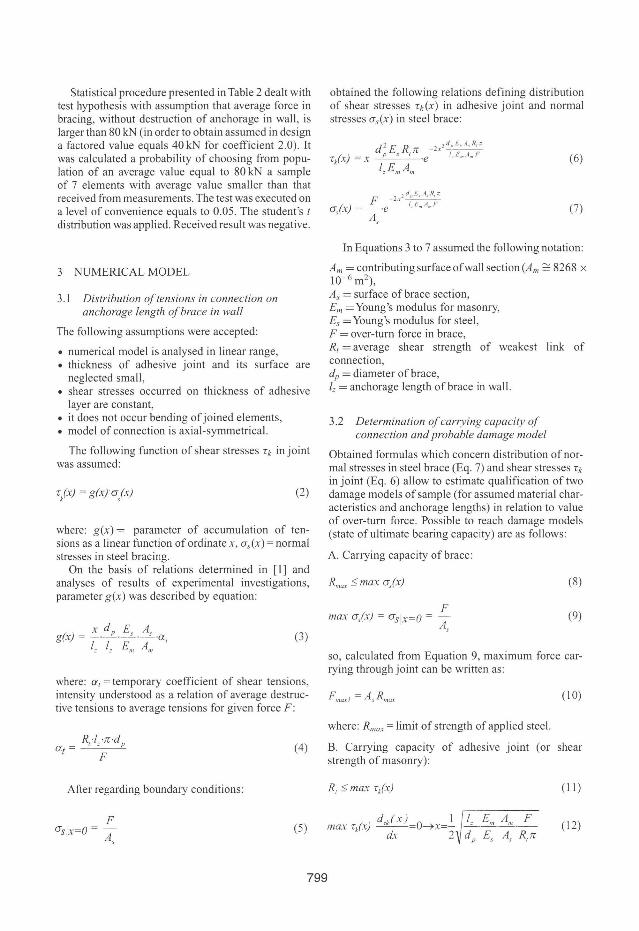
Statistical procedure presented in Table 2 dealt with test hypothesis with assumption that average force in bracing, without destruction of anchorage in wall , is larger than 80 kN (in order to obtain assumed in design a factored value equals 40 kN for coefficient 2.0). It was calculated a probability of choosing from population of an average value equal to 80 kN a sample of 7 elements with average value smaller than that received from measurements. The test was executed on a leveI of convenience equals to 0.05. The student's f
distribution was applied. Received result was negative.
3 NUMERlCAL MODEL
3.1 Distribution o(tensions in connection on anchorage length ofbrace in wall
The following assumptions were accepted:
• numerical model is analysed in linear range, • thickness of adhesive joint and its surface are
neglected small, • shear stresses occurred on thickness of adhesive
layer are constant, • it does not occur bending of joined elements, • model of connection is axial -symmetrical.
The following function of shear stresses ' k in joint was assumed:
(2)
where: g(x) = parameter of accumulation of tensions as a linear function of ordinate x , as (x) = normal stresses in steel bracing.
On the basis of relations determined in [1] and analyses of results of experimental investigations, parameter g(x) was described by equation:
(3)
where: a, = temporary coefficient of shear tensions, intensity understood as a relation of average destructive tensions to average tensions for given force F :
Afier regarding boundary conditions:
F as lx=O =
As
(4)
(5)
799
obtained the following relations defining distribution of shear stresses 'k(X) in adhesive joint and normal stresses as(x) in steel brace:
d 2 EsR,lr _2x,'!JE • .., . R •. ,
'lx) = x p .e I,E. A,J
I, Em A", (6)
(7)
In Equations 3 to 7 assumed the following notation:
Am = contributing surface ofwall section (Am ~ 8268 x 10- 6 m2),
As = surface of brace section, Em = Young's modulus for masonry, Es = Young's modulus for steel, F = over-turn force in brace, R, = average shear strength of weakest link of connection, dp = diameter of brace, '= = anchorage length ofbrace in wall.
3.2 Determination of carrying capacity of connection and probable damage model
Obtained formulas which concern distribution ofnormal stresses in steel brace (Eq. 7) and shear stresses 'k
in joint (Eq. 6) allow to estimate qualification of two damage models ofsample (for assumed material characteristics and anchorage lengths) in relation to value of over-turn force. Possible to reach damage models (state ofultimate bearing capacity) are as follows:
A. Carrying capacity of brace:
F max a,(r) = O's lx=O = A
s
(8)
(9)
so, calculated from Equation 9, maximum force carrying through joint can be written as:
Fmax' = As Rmllx (10)
where: Rmax = limit of strength of applied steel.
B. Carrying capacity of adhesive joint (or shear strength of masonry):
(11)
) d.dx) O I _I, .E",. A", ._F max rJ, - ' --= ---+x=-dx 2 d p Es As R,lr
( 12)
1 IdJ E 1 I max T
k(,) = -- ,} -1'_._ "-. _ _ ._ . F n R,
2 \ I, Em A, A", e (13)
so calculated from Equation 6 maximum force carrying throughjoint can be written as:
(14)
where: RI = average shear strength of weakest link of connection, Tmax = maximum shear stress of adhesive joint (joint or wall).
Real maximum force carrying through connection is smaller force calculated according to Equations 10 and 14:
(15)
3.3 Optimum anchorage length
Optimum anchorage length can be calculated after the formula of carrying capacity of adhesive joint (Eq. 14), substituting for maximum force F max2 value of force F , which can carrying that connection (in practical applications with suitable coefficients of safety).
(16)
under assumption:
F ::; Fma.r: / = A s R mQx ( 17)
Evidently it must be fu lfilled condition F :::: Fmax l ,
where Fmax2 is maximum force calculated for given type ofbrace (Eq. 10).
When we are using maximum of carrying capacity of steel as a one from elements of connection - substituting Equations 16 to 17 - we will receive formu la onto optimum anchorage length.
4 CONCLUSIONS
It should be noticed that nowadays in scientific and technical literature there is no complex and reliable information about system investigations of mentioned problem. The presented technical question is very important, especially for historical structures, when we want to avoid interference in façade ofbuilding, which usually has historical value. In this paper a method of constructional reinforcement was described, which moreover does not demand an execution of works outside a building. That considerably reduces cost
of works and makes easy organization of whole protection works.
The problem of connection of steel bracing with wall by using gluing techniques is a difficult one. In investigations one should take into account the following problems:
• determination of optimallength ofanchorage (sticking) steel bracing - as a function of wall endurance, steel, adhesive joint,
• adhesion and cohesion ofjoined elements in context of demanded damage model of joint,
• influence of others factors on endurance of joint (humidity of wall, a way of steel's surface development, axiality of sticking, temperature of environment) and its action in time,
• technology of insertion.
Nowadays, in the Building Engineering Institute of the Wroclaw University of Technology there are realised pilotage investigations on these problems. In these investigations epoxy resin produced by different producers are applied. Strength of connections: brick wall- steel bracing and distribution of shear stresses along the connection are studied. Length of sticking is differentiated. A special attention to damage model of joints is paid in investigations. Results ofthese investigations will make a basis to start spacious investigation programme.
The realised measurements of endurance of stuck steel bracings in the Monastery of Lubi'l.z are characterised by nega tive results. Basing of analyses and accessible knowledge on subject of steel sticking to various materiais it was stated that main causes of insufficient endurance were:
• insufficient endurance of adhesive joint, • big differentiated structure of walls and its
endurance parameters.
The received results were enough near to awaited ones, therefore works towards enlargement of endurance of joint for tensile adhesive joints: steel brace- brick wall were started. In order to enlarge contact surface sand-blasting of end parts inserted steel bracings was recommended. For holes executing it was recommended to use derrick DCM 1.5 (derrick, contrary to hammer, does not crumble material and does not spoil its structure but drills core of specified diameter). Additionally, diameter of holes was enlarged from cjJ30 to cjJ32 mm. These recommendations were connected with three principal problems:
• axiality of inserted steel bracing, • minimal adhesive envelope (~ l mm) around end
part of bracing, • protection of masonry structures against destruction.
However, investigations of others adhesive joints do not confirm positive influence of enlargement
800
of anehorage's length (more than 60 em) on a levei of shear stresses. Nevertheless, the authors reeommended enlargement of anehorage 's length to 120 em, in consideration of sureness insertion of steel braeing in non-homogeneolls wall (on a elear wish of designer of strengthening eonstruetion in a form of steel braeing). Furthermore, it was recommended to insert to hole more quantity of stronger epoxy resin, so as to outflow ofmixture from hole was visible afier insertion of steel bracings ends. Teclmological regime of holes executing and sticking was very strong. Installation of steel braeings was performed in June in environment temperature 18- 25°C, what determined the optimal temperature conditions for joints bonding. Nevertheless, electric drying of holes and their cleaning by means of compressed air were recommended. In view of bonding limited time installation of steel bracings in hole was reduced to 1.2 hour.
Afier realisation of above recommendations new investigations were performed on a population of 10 steel bracings. lt should be noticed that investigations were executing only to levei of force equal to 90 kN, which corresponding to designed forces in steel
801
bracings. The investigations were not continued until the damage of stuck steel bracings in view of high costs of experiment. Negative effects of steel bracings slides in area of insertion were not observed. Force levei of90 kN reached in investigations for permissible hypothesis (safety eoefficient equals 2), permitted to recognize that teehnology ofinsertion ofsteel bracings was reliable.
In the paper only selected problems of strengthening ofMonastery building construction by means ofstuck steel bracings were presented. In addition it should be stated that in a leveI of eoping there was executed a reinforced concrete eurb-plate, which stiffened walls and enlarged a possibility of carrying of roof counterties from large span roof. Series of routine repair works were also perfonned, but were not deseribed in a paper.
REFERENCE
Minch M. , Jasieríko 1. & Trochanowski A. 2000. Usztywnienie obiektów zaby tkoHych sralOl'l'ymi sciagallli wklejanYllli w //IU/y ., Inzynieria i Budownictwo, 56 (2): 144-147.
