strengthening effect of the shear key on the flexural behavior of concrete …c).pdf ·...
TRANSCRIPT

Steel Structures 6 (2006) 183-190 www.kssc.or.kr
Strengthening Effect of the Shear Key on the Flexural Behavior of
Concrete Filled Circular Tube
Young-Ho Kim1, Sung-Kun You1, Jae-Ho Jung2 and Soon-Jong Yoon3,*
1Sinil CNI Co., Ltd., Rm. 701 Baekgung Plaza III, 156-2 Jeongja-dong, Bundang-gu, Seongnam 463-834, Korea2Chun Il Eng. Consultants, 732-23 Yeoksam-dong, Gangnam-gu, Seoul 135-080, Korea
3Department of Civil Eng., Hongik University, 72-1 Sangsu-dong, Mapo-gu, Seoul 121-791, Korea
Abstract
In this study, the effect of slip behavior between steel tube and concrete on the flexural behavior of concrete filled steel tube(CFT) under pure bending was investigated experimentally and the effective method to increase the plastic moment capacityof CFT beam was suggested which is to install the shear key at the inside of steel tube. In order to obtain the strengtheningeffect of shear key installed inside the CFT, four point bending tests were performed. The ultimate strength, ductility, and failuremode of CFT beam with shear key was compared with those of hollow circular steel tube, CFT beam, CFT beam with endplate, and CFT beam strengthened by prestressing tendon. From the experimental study, it was found that the perfect bondingbehavior was essential for the composite action in the CFT beam with the shear key installed inside of the steel tube and theload carrying capacity of CFT beam was improved by installing the shear key as much as that of CFT beam strengthened byprestressing tendon.
Keywords: CFT (concrete filled steel tube) beam, End plate, Shear key, Prestressing tendon, Plastic slenderness ratio (d/t)
1. Introduction
The composite CFT member consisting of steel tube
filled with concrete is widely used, for the structures
which required large moment and ductile deformation,
due to its attractive advantages such as an excellent
seismic resistance in two orthogonal directions, a good
hysteresis under cyclic loading, a prevention of local
bucking of outer steel tube, and an enhancement of
ductility of CFT member up to the ultimate load. Those
advantages are mainly introduced by the structural
interactions between inner concrete and outer steel tube
such as a confinement of concrete by steel tube.
Many research results pertaining to the characteristic
behavior of CFT under axial compression are available.
However, the research on the structural behavior of CFT
under flexural loading is rarely conducted. The practical
application of the CFT as a pure flexural member had
been attempted in Japan for the construction of bridge. It
was a three span continuous railroad bridge using four
CFT girders with diameter of 1.3m (Hostaka et al., 1997,
Nakamura et al., 2002). Before the construction of CFT
girder bridge, 4-point bending test of CFT beam was
conducted to ensure the flexural performance of CFT
beam (Hosaka et al., 1997). Elchallakani et al. (2001)
suggested the limit of slenderness ratio (i.e., diameter to
thickness ratio, d/t) of steel tube to reach the plastic
moment (plastic slenderness ratio) based on the experimental
results. Lu et al. (1994) also examined CFT beams by
changing the slenderness ratio of steel tubes.
In these previous studies, the main considerations of
experiment were the slenderness ratio of steel tube and
the strength of infill concrete. They also reported that the
slip between steel tube and infill concrete did not so much
affect on the flexural capacity of CFT beam. It is true but
the load carrying capacity of CFT beam may increase if
the slip between steel tube and infill concrete is prevented.
In this study, we investigated the effective method to
increase the plastic moment capacity of CFT beam in
which the shear keys are installed in its inside. In order to
evaluate the effect of shear key installed inside, 4-point
bending tests were performed. The ultimate strength,
ductility, and failure mode of CFT beam with shear key
were compared with those of hollow circular steel tube,
CFT beam, CFT beam with end plate, and CFT beam
strengthened by prestressing tendon.
2. Test Specimens and Experimental Set-up
2.1. Test specimens
It is known that the plastic slenderness ratio, d/t, is one
of the most important factors affecting the structural
*Corresponding authorTel: +82-2-320-1479, Fax: +82-2-3141-0774E-mail: [email protected]
184 Young-Ho Kim et al.
behavior of CFT beam. According to the experimental
result of CFT performed by Chung (2003), the specimens
with slenderness ratio, d/t, from 29.6 to 56.4 reached the
plastic moment. By consideration of this result, we
prepared the steel tube specimen with slenderness ratio of
50.7. For the material of steel tube, SS400 was used
according to the Korean Specification for Highway
Bridges (2003).
In this study, we planed to investigate the effect of
shear key installed at the inner surface of steel tube on the
plastic moment capacity of CFT beam. Therefore, the
specimens were prepared by changing the resisting factors
of slip between steel tube and infill concrete. Table 1
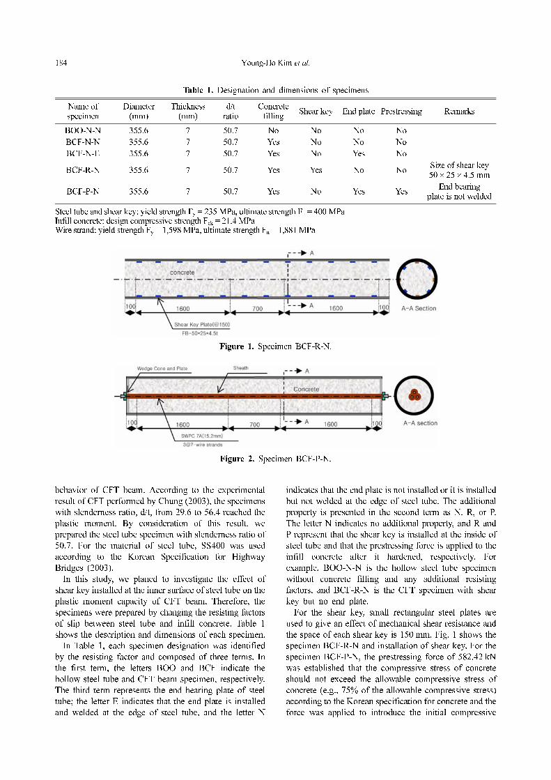
shows the description and dimensions of each specimen.
In Table 1, each specimen designation was identified
by the resisting factor and composed of three terms. In
the first term, the letters BOO and BCF indicate the
hollow steel tube and CFT beam specimen, respectively.
The third term represents the end bearing plate of steel
tube; the letter E indicates that the end plate is installed
and welded at the edge of steel tube, and the letter N
indicates that the end plate is not installed or it is installed
but not welded at the edge of steel tube. The additional
property is presented in the second term as N, R, or P.
The letter N indicates no additional property, and R and
P represent that the shear key is installed at the inside of
steel tube and that the prestressing force is applied to the
infill concrete after it hardened, respectively. For
example, BOO-N-N is the hollow steel tube specimen
without concrete filling and any additional resisting
factors, and BCF-R-N is the CFT specimen with shear
key but no end plate.
For the shear key, small rectangular steel plates are
used to give an effect of mechanical shear resistance and
the space of each shear key is 150 mm. Fig. 1 shows the
specimen BCF-R-N and installation of shear key. For the
specimen BCF-P-N, the prestressing force of 582.42 kN
was established that the compressive stress of concrete
should not exceed the allowable compressive stress of
concrete (e.g., 75% of the allowable compressive stress)
according to the Korean specification for concrete and the
force was applied to introduce the initial compressive
Table 1. Designation and dimensions of specimens
Name ofspecimen
Diameter(mm)
Thickness(mm)
d/tratio
Concretefilling
Shear key End plate Prestressing Remarks
BOO-N-N 355.6 7 50.7 No No No No
BCF-N-N 355.6 7 50.7 Yes No No No
BCF-N-E 355.6 7 50.7 Yes No Yes No
BCF-R-N 355.6 7 50.7 Yes Yes No NoSize of shear key50 × 25 × 4.5 mm
BCF-P-N 355.6 7 50.7 Yes No Yes YesEnd bearing
plate is not welded
Steel tube and shear key: yield strength Fy = 235 MPa, ultimate strength Fu = 400 MPaInfill concrete: design compressive strength Fck = 21.4 MPaWire strand: yield strength Fy = 1,598 MPa, ultimate strength Fu = 1,881 MPa
Figure 1. Specimen BCF-R-N.
Figure 2. Specimen BCF-P-N.

Strengthening Effect of the Shear Key on the Flexural Behavior of Concrete Filled Circular Tube 185
stress to the steel tube using three 7-wire strands
(φ15.2 mm). Fig. 2 shows the specimen BCF-P-N. When
the specimen BCF-P-N was prepared, the end bearing
plate was also used to apply the prestressing force to the
specimen but the edge of plate was not welded to the end
of steel tube in order to eliminate the effect of end plate.
Fig. 3 shows the specimens prepared.
2.2. Experimental Set-up
A 4-point bending test was prepared as shown in Fig.
4. According to experimental study by Kilpatrik (1997),
he recommended the shear span ratio of 2.7 to observe
the full load transfer without slip in the range of shear
span. Since the purpose of this experimental investigation
is to obtain the flexural load carrying capacity of CFT, we
designed the experimental set-up with shear span ratio of
4.5 as shown in Fig. 4. To minimize the local crippling of
steel tube, the loading and bearing devices were specially
fabricated for the two loading and reaction points as
shown in Fig. 5.
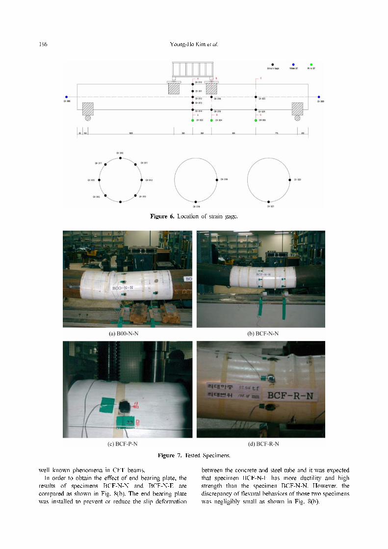
Steel strain gauges were attached on the outer surface
of steel tube in the circumferential direction to measure
strains at the center of test specimen. From the strain
measurement the location of neutral axis according to
each loading stage was traced. The displacement transducer
was also installed to measure the deflection at the center
of specimen. The location of strain gauges in the BCF
specimen is schematically shown in Fig. 6.
3. Comparison of Results
3.1. Failure modes
The hollow steel tube specimen B00-N-N was failed by
local crippling of steel tube in compression zone as
shown in Fig. 7(a). After the local crippling occurred, the
applied load was immediately decreased. In the specimens
BCF-N-N, BCF-N-E, and BCF-P-E, the compression
zone between loading points was expanded and the local
buckling occurred as shown in Figs. 7(b) and 7(c) but the
load was steadily increased after the local buckling
occurred. In the specimen BCF-R-N, the crack of steel
tube in tension zone was observed after the local buckling
occurred and finally the local crippling occurred as
shown in Fig. 7(d).
3.2. Load-deflection Behavior
Fig. 8 shows the load-deflection relation of test specimens.
First of all, the hollow steel tube specimen and CFT
specimen were compared in Fig. 8(a). In the figure, it is
clearly shown that the load carrying capacity of hollow
tube specimen is immediately decreasing after reaching
the ultimate strength of steel tube due to the local
buckling of steel tube in compression zone. On the other
hand, the descending part is not shown in the load-
deflection curve of the CFT specimen after yielding of
steel tube and the ductility and initial stiffness of CFT is
greater than those of hollow steel tube. Those results are
Figure 3. Test specimens.
Figure 4. Test set-up.
Figure 5. Details of bearing and loading devices.
186 Young-Ho Kim et al.
well known phenomena in CFT beams.
In order to obtain the effect of end bearing plate, the
results of specimens BCF-N-N and BCF-N-E are
compared as shown in Fig. 8(b). The end bearing plate
was installed to prevent or reduce the slip deformation
between the concrete and steel tube and it was expected
that specimen BCF-N-E has more ductility and high
strength than the specimen BCF-N-N. However, the
discrepancy of flexural behaviors of those two specimens
was negligibly small as shown in Fig. 8(b).
Figure 6. Location of strain gage.
Figure 7. Tested Specimens.

Strengthening Effect of the Shear Key on the Flexural Behavior of Concrete Filled Circular Tube 187
Fig. 8(c) shows the effect of shear key on the flexural
behavior of CFT. In the figure, the solid line without
symbol is the load-deflection curve of BCF-R-N which is
the CFT specimen with shear key and the solid line with
triangular symbol is the result of CFT specimen without
shear key. As shown in the figure, the stiffness and yield
load of specimen BCF-R-N are greater than those of
specimen BCF-N-N. Such higher yield strength and
stiffness may be caused by increasing the bonding
capacity between concrete and steel tube.
Fig. 8(d) shows the comparison of load-deflection curves
of specimens BCF-N-N and BCF-P-N. The stiffness and
ultimate strength of BCF-P-N specimen are higher than
those of specimen BCF-N-N since the prestressing force
applied to specimen BCF-P-N reduces the tensile stress
of steel tube and slip between steel tube and concrete.
From the above results, it is found that the load
carrying capacity and the stiffness of specimen BCF-R-N
are improved and the increase of ultimate strength and
stiffness is similar to those of specimen BCF-P-N. This
increase is caused by the inter-rocking action of shear key
and concrete, that is, the shear keys restrain the slip of
concrete and those restricting forces transfer to steel tube.
Then, the tensile strain of steel tube may be reduced due
to similar action as prestressing force. This phenomenon
is illustrated in next section.
3.3. Load-slip behavior
In order to investigate the slip behavior between steel
tube and concrete, the slip at the ends of each specimen
was measured. Fig. 8. illustrates the load-slip behavior of
specimens BCF-N-N and BCF-R-N. As shown in the
figure, the maximum slip measured in the specimen BCF-
N-N during experiment was 4.2 mm, however, negligibly
small amount of slip was observed in the specimen BCF-
R-N. From the result, it is found that the shear key is
effectively restricting the slip between steel tube and
concrete.
To investigate the contact surface between steel tube
and concrete, we cut the steel tube and observed the
surface of concrete of specimen BCF-R-N after failure.
As shown in Fig. 10, the crushing trace of concrete can
be observed at the location of shear key toward the
support and this trace illustrates the mechanical resisting
effect of shear key on the slip between steel tube and
concrete.
3.4. Neutral axis
Fig. 11 shows the transition of neutral axis in tested
specimens at each loading stage. The steel strains measured
in the composite beam are significantly different from the
steel strains measured in the hollow steel beam. For the
hollow section beam, the experimental measurement on
Figure 8. Load-deflection Relations.

188 Young-Ho Kim et al.
the location of neutral axis shows that the neutral axis
coincides with central axis of the section as increase of
the applied load but the tensile strain is increased after
local buckling occurs at the compression zone of steel
tube. In the CFT beam specimen, the location of neutral
axis is unchanged for small moments, but just after the
crack of concrete initiates, the location of neutral axis
shifts rapidly upward as the length of crack increase.
Especially, the neutral axis moves upward as much as
132.6 mm from its original position in the specimen
BCF-R-N. Tensile strains of concrete infilled steel tube
are much greater simply because of the fact that the
tensile force in the steel must balance the compressive
force in combined steel and concrete.
Figure 9. Slip measurement and view of the slip.
Figure 10. Concrete surface of specimen BCF-R-N after Failure.

Strengthening Effect of the Shear Key on the Flexural Behavior of Concrete Filled Circular Tube 189
In addition, the restraining effect of shear key is also
evaluated in those measured strain. As shown in Fig.
11(b), (c), and (d), the strains of steel tube of specimen
BCF-R-N are much smaller than those of other specimens
before reaching its maximum load. This phenomenon
also illustrates the restraining effect of shear key on the
slip between steel tube and concrete.
4. Conclusions and Discussions
In this study, the experimental investigations on the
flexural behavior of CFT beams were performed. To
increase the load carrying capacity of CFT beam, the
method of installing shear key elements at the inside of
steel tube was suggested and its performance was
evaluated experimentally. From the experiments, it was
found that the perfect bonding is essential for the
composite action in CFT beam by installing the shear key
at the inside of the steel tube and the load carrying
capacity of CFT beam with shear key improved as much
as CFT beam strengthened by prestressing tendon. It was
also found that those improvements are achieved by
enhancing the bonding capacity between steel tube and
concrete.
In the previously published works (Lu et al., 1994;
Kilpatrick et al., 1997), it was reported that the slip
between steel tube and concrete does not seriously affect
the load carrying capacity of CFT beams. It is true when
the high strength concrete is used. In addition, to reduce
the self-weight of CFT beam, it is necessary to use the
light weight concrete. In this experimental investigation,
the use of shear key at the inside of steel tube is examined
to improve the flexural load carrying capacity.
In this experimental study, only one type of shear keys
was used, and the composite action between deck slab
and CFT beam was not considered. Therefore, further
experimental researches on effective types of shear key
are necessary to develop the rational design guideline for
the CFT under flexural loading.
References
Chung, C.H., Kim, Y.J., and Kim, S.U. (2003). “A Study on
Analysis and Design of Composite Bridge with Concrete
Filled Tubes,” Research Report, Daewoo Technical
Research Center, Suwon.
Elchallakani, M., Zhao X.L., and Grzebieta, R.H. (2001).
“Concrete Filled Circular Steel Tubes Subjected to Pure
Bending,” Journal of Constructional Steel Research, Vol.
57, p.1141-1168.
Hosaka, T., Umehara, T., Nakamura, S., and Nishiumi, K.
(1997). “Design and Experiments on a New Railway
Bridge System Using Concrete Filled Steel Pipes,”
Figure 11. Neutral axis of BOO-N-N, BCF-N-N, BCF-N-E, and BCF-R-N.

190 Young-Ho Kim et al.
ASCCS Seminar, Concrete Filled Steel Tubes, A
Comparison of International Codes and Practices,
Innsbruck, Austria, p.367-372.
Kilpatrik, A.E. and Rangan, B.V. (1997). “Tests on High-
strength Composite Concrete Column,” Research Report,
No. 1, Curtin University of Technology, Australia.
Korean Specification for Highway Bridge (2003). Korean
Society of Civil Engineers.
Lu, Y.Q., Kennedy, D.J.L. (1994). “The Flexural Behavior of
Concrete-Filled Hollow Structural Section,” Canadian
Journal of Civil Engineering, Vol. 21, No. 1, p. 111-130.
Nakamura, S., Momiyama, Y., Hosaka, T., and Homma, K.
(2002). “New Technologies of Steel/Concrete Composite
Bridges,” Journal of Constructional Steel Research, Vol.
58, p. 99-130.