strength of gas tungsten arc welding joint mohd
TRANSCRIPT
STRENGTH OF GAS TUNGSTEN ARC WELDING JOINT
MOHD NOR RIZUAN BIN JAMALUD1N
A report submitted in partial fulfillment of the
requirements for the award of degree of
Bachelor of Mechanical Engineering
Faculty of Mechanical Engineering
Universiti Malaysia Pahang
NOVEMBER 2007
ABSTRACT
Welder that involve in small business obviously not using gas tungsten arc
welding because of the high cost. This welding is suitable for materials that have a high
ability of strength. This welding often use in heavy and middle industry and the strength
of the welding joint is proven by the majority of the heavy industry like piping. The
advantage of using gas tungsten arc welding are the strength and do not have to use the
grinder because the surface of the weld is already smooth. Skill and technique of handle
the current and material that used to this welding is very useful because it complex than
others. Stainless steel and mild steel is used in this project and the material is weld in tee
joint. butt joint and lan joint. To test the joinin g that been weld. instron tensile machine
is used. The study shows that stainless steel that use lan joint has a maximum stren2th
that is 0.97255 MPa. The study also show that the joint is effect the stren gth of the
weidin. and foi that the suitable joint that use is lan joint.
ABSTRAK
Kimpalan arka tungsten adalah suatu jenis kimpalan yang jarang digunakan oleh
perniagaan mengimpal yang berskala keell kerana kos yang mahal. Kimpalan mi sesuai
digunakan untuk mengimpal besi yang mempunyai ketahanan yang tinggi seperti
aluminum dan besi yang tidak berkarat. Penggunaannya lebih kepada industri berat dan
sederhana. Kekuatan kimpalan mi terbukti dengan banyak digunakan di industri berat
seperti mengimpal paip besi. la mempunyai kelebihan kerana tidak perlu dicanai dan
struktur pada kimpalan lebih kukuh berbanding menggunakan jenis kimpalan yang lain.
Teknik serta skil diper!ukan untuk mengendali kimpalan mi, dari segi ants elektrik serta
material yang digunakan. Material seperti logam tahan karat serta logam lembut
digunakan. Cantuman berbentuk T, hujung ke hujung serta lipatan digunakan untuk
menguji kekuatan kimpalan. Eksprimen tegangan dilakukan dengan menggunakan
mesin Instron. Keputusan telah menunjukkan bahawa kekuatan yang paling tinggi
adalah pada logam yang tidak berkarat yang menggunakan cantuman lipatan iaitu
0.97255 MPa. Kajian telah mendapati bahawa cantuman memberi kesan kepada
kekuatan kimpalan itu. Maka jenis cantuman lipatan adalah paling sesuai antara tiga
jenis cantuman tadi.
A
TABLE OF CONTENTS
CHAPTER TITLE PAGE
- TITLE PAGE I
STUDENT DECLARATION
DEDICATION
ACKNOWLEDGEMENT iv
ABSTRACT v
AIBSTRAK vi
TABLE OF CONTENT vii
LIST OF TABLE x
LIST OF EQUATIONS xi
LIST OF FIGURE xii
LIST OF SYMBOL xiv
LIST OF APPENDICES xv
INTRODUCTION 1
1.1 Introduction 1
1.2 Problem Statements I
1.3 Project Objective I
1.4 Project Scope 2
1.5 Project Background 2
VII
viii
2 LITERATURE REVIEW 3
2.1 History 3
2.2 Type of Welding
2.2.1 Shielded Metal Arc Welding (SMAW) 4
2.2.2 Gas metal Arc Welding (GMAW) 4
2.2.3 Oxyacetylene Welding 5
2.2.4 Gas Tungsten Arc Welding (GTAW) 6
2.3 Technical Description of Tungsten Inert Gas 7
2.4 The Basic Types of Welding Joint 9
2.5 Discontinuities And Defects 13
2.5.1 Porosity 14
2.5.2 Overlap 14
2.5.3 Crater Cracks 14
2.5.4 Lamination 14
2.5.5 Delamination 15
2.6 Equipments 17
2.6.1 Tensile Test 17
2.6.2 Charpy and Izod Test 18
2.6.3 Rockwell Test. 19
3 METHODOLOGY 21
3.1 Introduction 21
3.1.1 Flow Chart 22
3.2 Specimens 23
3.2.1 Mild Steel 23
3..2.2 Stainless Steel 23
3.3 Equipments For Welding 24
3.3.1 Tungsten Inert Gas (TIG) 24
3.3.2 Torch 24
3.3.3 Power Supply 25
3.3.4 Electrode 25
ix
3.3.5 Shielding Gas 26
3.4 Design of Joint and Degree of Torch 27
3.5 Machine to Test the Strength 28
4 RESULTS AND DISCUSSION 32
4.1 Result 32
4. 1.0 Introduction 32
4. 1.1 The Strength of Tungsten Arc Welding for Mild 32
Steel
4.1.2 The Strength of Tungsten Arc Welding for 35
Stainless Steel
4.2 Discussion 37
4.2.1 Mild Steel 37
4.2.2 Stainless Steel 38
5 CONCLUSION AND RECOMMENDATION 40
5.1 Conclusion 40
5.2 Recommendation 41
REFERENCES 42
Appendices A-B 43
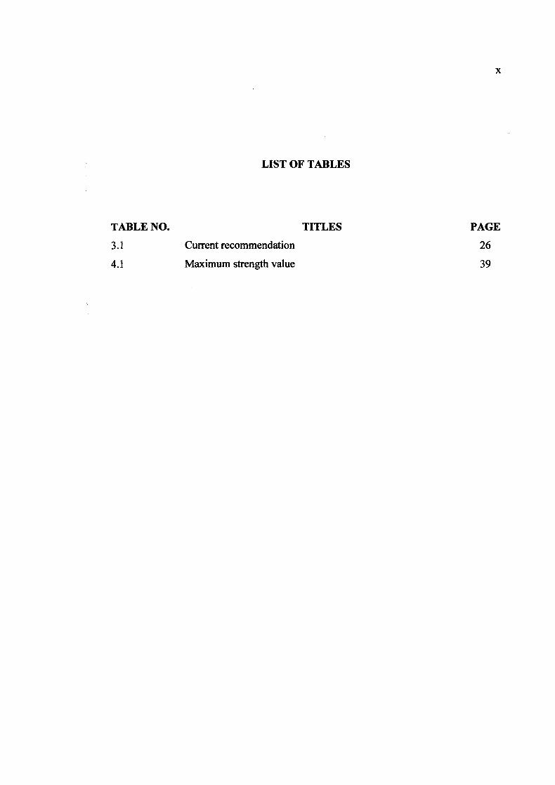
LIST OF TABLES
TABLE NO. TITLES PAGE
3.1 Current recommendation
4.1 Maximum strength value 39

LIST OF EQUATION
EQUATION NO. EQUATION PAGE
2.1 Ei = (Lf—Lo/Lo) x 100
xi
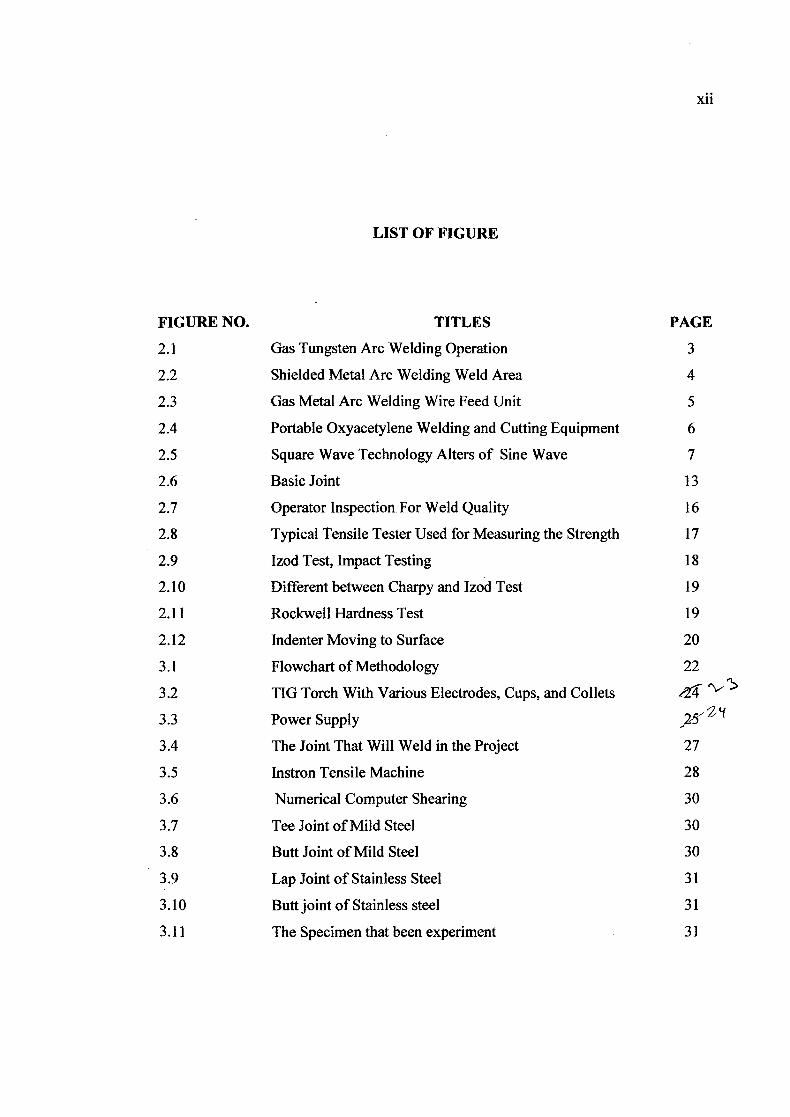
LIST OF FIGURE
FIGURE NO. TITLES PAGE
2.1 Gas Tungsten Arc Welding Operation 3
2.2 Shielded Metal Arc Welding Weld Area 4
2.3 Gas Metal Arc Welding Wire Feed Unit 5
2.4 Portable Oxyacetylene Welding and Cutting Equipment 6
2.5 Square Wave Technology Alters of Sine Wave 7
2.6 Basic Joint 13
2.7 Operator Inspection For Weld Quality 16
2.8 Typical Tensile Tester Used for Measuring the Strength 17
2.9 Izod Test, Impact Testing 18
2.10 Different between Charpy and Izod Test 19
2.11 Rockwell Hardness Test 19
2.12 Indenter Moving to Surface 20
3.1 Flowchart of Methodology 22
3.2 TIG Torch With Various Electrodes, Cups, and Collets
3.3 Power Supply
3.4 The Joint That Will Weld in the Project 27
3.5 Instron Tensile Machine 28
3.6 Numerical Computer Shearing 30
3.7 Tee Joint of Mild Steel 30
3.8 Butt Joint of Mild Steel 30
3.9 Lap Joint of Stainless Steel 31
3.10 Butt joint of Stainless steel 31
3.11 The Specimen that been experiment 31
xli
xlii
4.1 Graph of mild steel for butt joint weld 32
4.2 Graph of mild steel for lap joint weld 33
4.3 Graph of mild steel for tee joint weld 34
4.4 Graph of stainless steel for butt joint weld 35
4.5 Graph of stainless steel for lap joint weld. 35
4.6 Graph of stainless steel for tee joint weld 36
4.7 Graph of Stress versus Strain for mild steel 37
4.8 Graph of Stress versus Strain for stainless steel 38
LIST OF SYMBOLS
GTAW- Gas Tungsten Arc Welding
Ei - Percent of Elongation
Lf - New Elongation
Lo - Elongation by Gauge Length
MPa - Mega Pascal
KN - Kilo Newton
UTS - Ultimate Tensile Stress
xiv
xv
LIST OF APPENDICES
APPENDIX TITLE PAGE
A Table of electrode 43
BI Flow Chart FYP I
44
B2 Gant Chart FYP 1 45
CHAPTER 1
INTRODUCTION
1.1 Introduction
Welding is a process critical to our present state of civilization and
technical advancement. In this era, the technology of welding more advance and give
many advantage to mankind. From the simplest shape like table until the complex like
construction of space shuttle, the used of welding is very important. The technology of
welding has been used in the sea, land and even at the space. The purpose of welding is
to joint and give the strength to the material from being fracture.
1.2 Problem Statement
The design of the joint may not suitable for some condition, the design
may not ergonomically and the strength of joining is not very good. These problems
arise because of affected by the environment and the outside force. The strength of
joining may not same for 3 or 4 years after being weld. The skill for welding is very
important to get the good result and minimize delamination.
1.3 Project objective
a) To measure the strength of gas tungsten arc welding joint.
2
1.4 Project scope
a) To fabricate specimen for testing
b) To test the joining strength
c) To study factors that affecting the strength
1.5 Project background
Gas tungsten arc welding (GTAW) will be used as a welding technique in this
project. The experiment was done to understand the factors contribute to the welding
weakness. The procedure shall be carried out to get an optimum welding joint strength.
The factors that affected the strength of the joint such as an angle of the material to
weld, the right power to use and defect like porosity, lamination, delaminations will be
analyzed in the project.

CHAPTER 2
LITERATURE REVIEW
2.1 History
The development of the GTAW process was accelerated early in 1940.
Initially the process was called "Heliarc", because Helium was used for the shielding
gas. Later when argon was available the process was renamed tungsten inert gas or
"TIG".
Direction of GTA'Whe,d weed
J^oing gas
Coaled rjbe Fp Tungsten trade
- : ac Weld bead
Copper shoe - \ - Shfe:dng ge's
Figure 2.1: Gas Tungsten Arc Welding Operation
Now, it is generally and preferably called gas tungsten arc welding (GTAW),
as gases other than argon and helium, which are inert, can be mixed with them.
Hydrogen, for example, may be included for its special benefits. The development of
aircraft in the World War 2 make the researcher use TIG as intensive for joining such
non-ferrous material such as aluminium and magnesium. The process can be used to
weld thin or thick materials with or without a filler metal. Development within the
GTAW process has continued as well, and today a number of variations exist. Among

4
the most popular are the pulsed-current, manual programmed, hot-wire, dabber, and
increased penetration GTAW methods. (Cary, Howard B. and Scott C. Heizer ;2005)
2.2 Types Of Welding
2.2.1 Shielded Metal Arc Welding (SM_AW)
Shielded metal arc welding (SMAW), also known as manual metal arc (MMA)
welding or informally as stick welding, is a manual arc welding process that uses a
consumable electrode coated in flux to lay the weld. An electric current, in the form of
either alternating current or direct current from a welding power supply, is used to form
an electric arc between the electrode and the metals to be joined. As the weld is laid, the
flux coating of the electrode disintegrates, giving off vapors that serve as a shielding gas
and providing a layer of slag, both of which protect the weld area from atmospheric
contamination. SMAW is often used to weld carbon steel, low and high alloy steel,
1L1 cr UZ
GF1^1flM OR
AI Y ri
(s-,cs SLE
SUZ
zo
1 aa^
EZZ) CS
Figure 2.2: Shielded metal arc welding weld area
stainless steel, cast iron, and ductile iron. While less popular for nonferrous materials, it
can be used on nickel and copper and their alloys and, in rare cases, on aluminum. The
thickness of the material being welded is bounded on the low end primarily by the skill
of the welder, but rarely does it drop below 0.05 in (1.5 mm). No upper bound exists:
with proper joint preparation and use of multiple passes, materials of virtually unlimited
5
thicknesses can be joined. Furthermore, depending on the electrode used and the skill of
the welder, SMAW can be used in any position. (Jeffus, Larry ;1999).
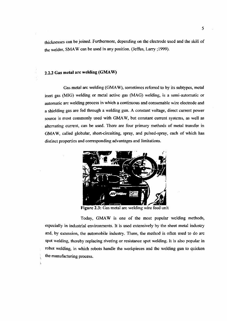
2.2.2 Gas metal arc welding (GMAW)
Gas metal arc welding (GMAW), sometimes referred to by its subtypes, metal
inert gas (MIG) welding or metal active gas (NAG) welding, is a semi-automatic or
automatic arc welding process in which a continuous and consumable wire electrode and
a shielding gas are fed through a welding gun. A constant voltage, direct current power
source is most commonly used with GMAW, but constant current systems, as well as
alternating current, can be used. There are four primary methods of metal transfer in
GMAW, called globular, short-circuiting, spray, and pulsed-spray, each of which has
distinct properties and corresponding advantages and limitations.
Figure 2.3: Gas metal arc welding wire feed unit
Today, GMAW is one of the most popular welding methods,
especially in industrial environments. It is used extensively by the sheet metal industry
and, by extension, the automobile industry. There, the method is often used to do arc
spot welding, thereby replacing riveting or resistance spot welding. It is also popular in
robot welding, in which robots handle the workpieces and the welding gun to quicken
the manufacturing process.
2.2.3 Oxyacetylene Welding
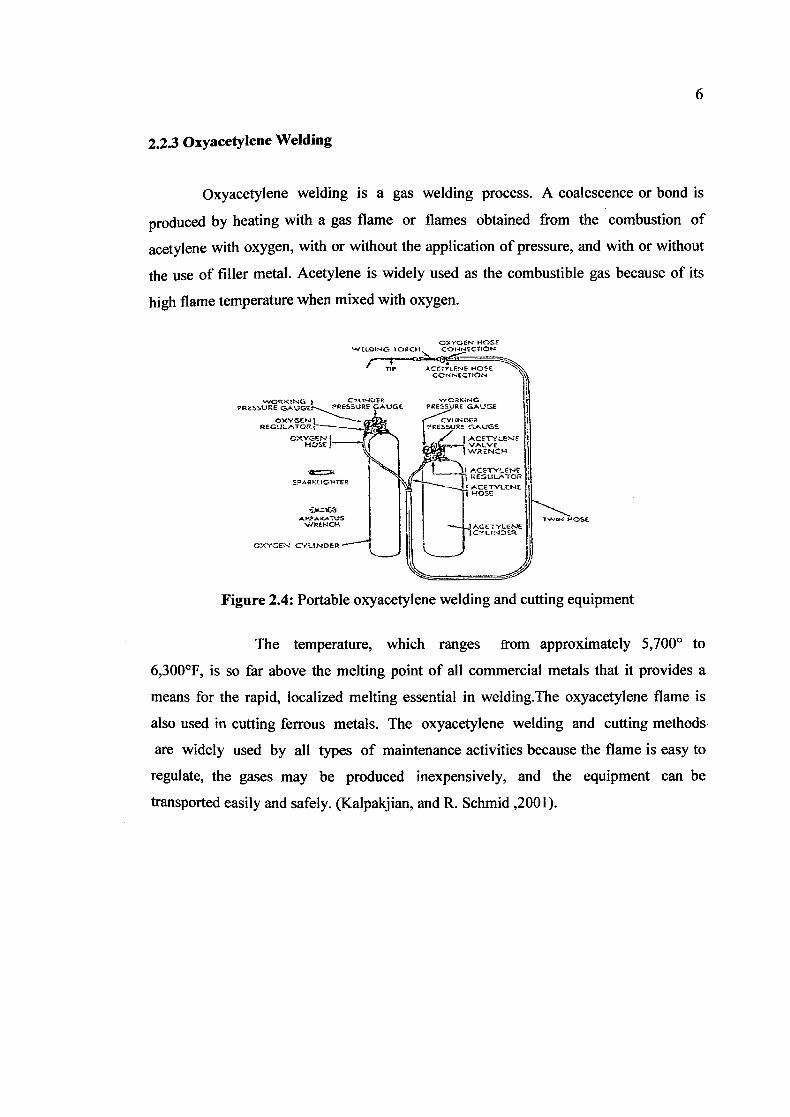
Oxyacetylene welding is a gas welding process. A coalescence or bond is
produced by heating with a gas flame or flames obtained from the combustion of
acetylene with oxygen, with or without the application of pressure, and with or without
the use of filler metal. Acetylene is widely used as the combustible gas because of its
high flame temperature when mixed with oxygen.
CL-IDER WC.NG PRESSURE G Er..PESSUEE GAUGE PRESSURE GAUGE
EGJLATCt _. CXY€ --
E4SE r VALVE 1WENZ-I
*=Me ACETYLCNE 5I GEEII
\l'T''- I ACETYLENE
1
ROSE
P WREKCH
I IL.I)k
OXYGEN CYLINDER 1 II
Figure 2.4: Portable oxyacetylene welding and cutting equipment
The temperature, which ranges from approximately 5,7000 to
6,300°F, is so far above the melting point of all commercial metals that it provides a
means for the rapid, localized melting essential in welding.The oxyacetylene flame is
also used in cutting ferrous metals. The oxyacetylene welding and cutting methods
are widely used by all types of maintenance activities because the flame is easy to
regulate, the gases may be produced inexpensively, and the equipment can be
transported easily and safely. (Kalpakjian, and R. Schmid ,2001).
7
2.2.4 Gas Tungsten Arc Welding (GTAW)
(GTAW) Gas tungsten arc welding provides high-quality welds because
of the gas shielding of the molten weld pool. The welding arc is created between a
tungsten electrode, which is non-consumable, and the weld pool. The welding can be
autogenous (without filler material), or with filler rod/wire. Because of the shielding and
high concentration of heat it is used on refractory and reactive metals which oxidize
readily without inert gas protection.
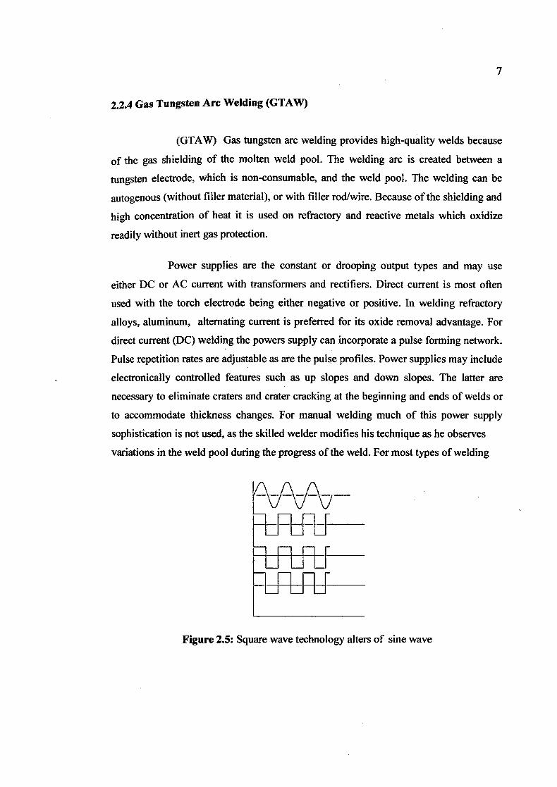
Power supplies are the constant or drooping output types and may use
either DC or AC current with transformers and rectifiers. Direct current is most often
used with the torch electrode being either negative or positive. In welding refractory
alloys, aluminum, alternating current is preferred for its oxide removal advantage. For
direct current (DC) welding the powers supply can incorporate a pulse forming network.
Pulse repetition rates are adjustable as are the pulse profiles. Power supplies may include
electronically controlled features such as up slopes and down slopes. The latter are
necessary to eliminate craters and crater cracking at the beginning and ends of welds or
to accommodate thickness changes. For manual welding much of this power supply
sophistication is not used, as the skilled welder modifies his technique as he observes
variations in the weld pool during the progress of the weld. For most types of welding
Figure 2.5: Square wave technology alters of sine wave
8
this high frequency is used only to initiate the arc, but for aluminum GTAW, the high
frequency is present continuously and acts like a pilot arc. When selecting a power
source, it usually is best to select a newer-technology square wave model, which alters
the characteristics of the sine wave to create a more stable arc.
For GTA welding of carbon and stainless steel, the selection of a filler
material is important to prevent excessive porosity. Oxides on the filler material and
workpieces must be removed before welding to prevent contamination, and immediately
prior to welding, alcohol or acetone should be used to clean the surface. Preheating is
generally not necessary for mild steels less than one inch thick, but low alloy steels may
require preheating to slow the cooling process and prevent the formation of martensite in
the heat-affected zone. Tool steels should also be preheated to prevent cracking in the
heat-affected zone. Austenitic stainless steels do not require preheating, but martensitic
and ferritic chromium stainless steels do. (Minnick, 1996).
2.3 Technical description of Tungsten Inert Gas
Before Welding Starts: Steps 1-4
The following steps and suggestions address the basic areas of GTAW setup.
However, they are no substitute for carefully reading the operator's manual, watching.
instructional videos, and following safety precautions such as wearing protective gloves
and glasses.
2.3.1 Determine amperage requirements.
Each 0.001 inch of metal to be melted requires about 1 amp of welding power.
For example, welding 1/8-inch aluminum requires about 125 amps.
2.3.2 Select the correct current.
AC should be used for aluminum, magnesium, and zinc die cast. When
exposed to air, these metals form an oxide layer that melts at a much higher temperature
than the base metal. If not removed, this oxide causes incomplete weld fusion.
Fortunately, AC inherently provides a cleaning action. While the EN portion of the AC
cycle directs heat into the work and melts the base metal, the EP portion—where current
flows from the work to the electrode—blasts off the surface oxides.
2.33 Use the right gas.
Usually, pure argon is employed, although thicker weidments may require an
argon/helium or other specialty mix. If the wrong gas is used, the tungsten immediately
will be consumed or deposited in the weld puddle.
10
2.3.4 Set the proper gas flow rate.
More is not better, so 15 to 20 cubic feet per hour (CFH) should suffice. Argon
is about 1-1/3 heavier than air. When used to weld in a flat position, the gas naturally
flows out of the torch and covers the weld pool. For overhead welding, the gas flow rate
should begin at 20 CFH, and small increments of 5 CFH can be made, if necessary.
In any position, if the gas flows out at too high a velocity, it can start a swirling motion
parallel to the torch cup, called a venturi. A venturi can pull air into the gas flow, bring
in contaminating oxygen and nitrogen, and create pinholes in the weld. Unfortunately,
some operators automatically increase the gas flow when they see a pinhole, worsening
the problem.
Before Welding Starts: Steps 5-12
2.3.5 Select the right type of tungsten.
However, for making critical welds on materials thinner than 0.09 inch, or
when using a GTAW power source with an adjustable frequency output, new
recommendations call for treating the tungsten almost as if the weld were being made in
the DC mode. A 2 percent-type tungsten (thorium, cerium, etc.) should be selected and
ground to a point in the long direction, making the point roughly two times as long as
the diameter. A 0.010- to 0.030-inch flat should be made on the end to prevent balling
and the tungsten from being transferred across the arc.
With a pointed electrode, a skilled operator can place a 1/8-inch bead on a
fillet weld made from 1/8-inch aluminum plates. Without this technology, the ball on the
end of the electrode would have forced the operator to make a larger weld bead and then
grind the bead down to final size.
11
2.3.6 Select the right diameter of tungsten.
The current-carrying capacity of a tungsten is directly proportional to the
area of its cross section.. For example, a 2 percent thoriated, 3/32-inch (0.093-inch)
tungsten has a current-carrying capacity of 150 to 250 amps, whereas a 2 percent
thoriated, 0.040-inch tungsten has a 15- to 80-amp capacity.
There is no such thing as an all-purpose electrode, despite the reputation of
the 3/32-inch electrode. Attempting to weld at 18 amps with a 3/32-inch electrode will
create arc starting and stability problems; the current is insufficient to drive through the
electrode. Conversely, attempting to use a 3/32-inch tungsten to weld at 300 amps
creates tungsten "spitting"—the excess current causes the tungsten to migrate to the
workpiece.
2.3.7 Avoid tungsten contamination.
If the tungsten electrode becomes contaminated by accidentally touching
the weld pool, welding must be stopped, because a contaminated electrode can produce
an unstable arc. To break off the contaminated portion, the tungsten should be removed
from the torch, placed on a table with the contaminated end hanging over the edge, and
the contaminated portion struck firmly. The tungsten then should be resharpened.
23.8 Set the proper tungsten extension.
Electrode extension may vary from flush with the gas cup to a distance
equal to the cup diameter. A general rule is to start with one electrode diameter, or about
1/8 inch. Joints that make the root of the weld hard to reach require additional extension,
although extensions farther than 1/2 inch may result in poor gas coverage and require a
special gas cup.

12
2.3.9 Select the correct filler metal.
The filler rod needs to be appropriate for the base metal in terms of type
and hardness. It should be the same diameter as the tungsten electrode. The welder
should refer to charts published by filler metal manufacturers detailing what filler to use
for what base metal.
2.3.10 Select a high-frequency (HF) mode.
Inverters require HF for arc starting only because they drive the arc
through the zero point so quickly that the arc does not have a chance to go out. For this
same reason, inverters produce much less arc flutter. They also offer a lift arc starting
method that avoids the use of hF altogether.
2.3.11 Control HF emissions.
High frequency interferes with computers, printed circuit boards,
televisions, and other electronic equipment but is a necessary evil. It can be minimized
by hooking the work clamp as close to the weldment as possible, keeping the welding
torch and clamp cables close together (spreading them apart is like creating a big
broadcast dish), and keeping the cables in good condition to prevent current leaks.
2.3.12 Set the balance control
• • Too much cleaning action (EP duration) causes excess heat buildup on
the tungsten, which creates a large ball on the end. Subsequently, the arc loses stability,
and the operator loses the ability to control the arc's direction and the weld puddle. Arc
starts begin to degrade as well. (Mike Sammons, 19 February 2001)