streets and highways (h) - lincoln, ca
TRANSCRIPT
PUBLIC FACILITIES IMPROVEMENT STANDARDS
SECTION 3
STREETS AND HIGHWAYS (H)
3-1 General ......................................................................................................... H-1 3-2 Connection to Existing Improvements .................................................................. H-2
A. Cuts in Existing Streets ............................................................................ H-2 B. Street Widening ....................................................................................... H-2 C. Existing Stub Street Connection ............................................................... H-3 D. Existing Utility Connection Including Hot Taps ......................................... H-3
3-3 Construction Staking ............................................................................................ H-3 3-4 Utility Relocation................................................................................................... H-3 3-5 Trench Work ......................................................................................................... H-4
A. Existing Surface ....................................................................................... H-4 B. Water in Trench ........................................................................................ H-5 C. Unsuitable Trench Bottom ........................................................................ H-5 D. Open Trench ............................................................................................ H-5 E. Steel Trench Plates .................................................................................. H-6 F. Temporary Surfacing ................................................................................ H-6
3-6 Utility Trench Backfill QA/QC ......................................................................... H-6 A. Performance Based QA/QC (Non-Testable Materials) ............................ H-6 B. Design Based QA/QC (Testable Materials) .............................................. H-6 C. Trench Backfill Material ............................................................................ H-7
1. Type “A” Material ........................................................... H-7 2. Type “B” Material ........................................................... H-7 3. Type “C” Material ........................................................... H-7 4. Type “D” Material ........................................................... H-7 5. Type “E” Material ........................................................... H-7
D. Pipe Zone Backfill ..................................................................................... H-8 E. Compaction Test Methods ....................................................................... H-8 F. Testing Frequencies ................................................................................. H-8 G. Manhole Structure Backfill ........................................................................ H-9
3-7 Roadway Construction ................................................................................... H-9 A. Pavement Design Methods ....................................................................... H-10 B. Wet Weather Construction Extended Warranties ..................................... H-10 C. Trench Backfill Material ............................................................................. H-10 D. Roadway Base .......................................................................................... H-11 E. Native Soul Subgrade ............................................................................... H-11
1. Scarification and Moisture Conditioning .................................................. H-11 2. Subgrade Treatment ............................................................................... H-11 3. Grading ................................................................................................... H-11 4. Compaction ............................................................................................. H-12 5. Stability ................................................................................................... H-12
F. Aggregate Base (AB) ................................................................................ H-12 1. Thickness ................................................................................................ H-13

PUBLIC FACILITIES IMPROVEMENT STANDARDS
2. Grading ................................................................................................... H-13 3. Compaction ............................................................................................. H-13 4. Stability ................................................................................................... H-13
G. Concrete Curb, Gutter and Sidewalk ........................................................ H-14 1. Thickness ................................................................................................ H-14 2. Reinforcing .............................................................................................. H-14 3. Finishing .................................................................................................. H-15 4. Sidewalk Access Ramps ......................................................................... H-15 5. Expansion joints, deep tool joints and score marks ................................ H-15 6. Grades .................................................................................................... H-16 7. Monolithic Sidewalk, Curb and Gutter ..................................................... H-16 8. Under Sidewalk Drainage Pipe ............................................................... H-16 9. Curb and Gutter Installation In An Existing Street................................... H-16 10. Epoxy Work ............................................................................................. H-17 11. Median Noses ......................................................................................... H-17
H. Asphalt Concrete ...................................................................................... H-17 1. Construction ............................................................................................ H-17 2. Testing .................................................................................................... H-18
I. Raisin Iron to Finished Grade ................................................................... H-19 J. Final Seal Coat in Residential Area .......................................................... H-20 K. Crack and Joint Sealing ............................................................................ H-21 L. Sound and Retaining Walls and Graffiti Coating ....................................... H-21 M. Street Barricades ...................................................................................... H-21 N. Street Signs .............................................................................................. H-21 O. Street Sign Posts ...................................................................................... H-21 P. Survey Monuments ................................................................................... H-22
3-8 Traffic Stripes and Pavement Markings ....................................................... H-23 A. Removal of Existing .................................................................................. H-23 B. Application ................................................................................................ H-23 C. Thermoplastic Material .............................................................................. H-23 D. Pavement Markers .................................................................................... H-24
3-9 Materials ...................................................................................................... H-25 A. Aggregate Base ........................................................................................ H-25 B. Asphalt Concrete ...................................................................................... H-26 C. Concrete ................................................................................................... H-26 D. Concrete Additives .................................................................................... H-26 E. Lime .......................................................................................................... H-26 F. Truncated Domes ..................................................................................... H-27 G. Expansion Joint Filler ................................................................................ H-27 H. Graffiti/Anti Graffiti ..................................................................................... H-27 I. Filter Fabric ............................................................................................... H-27 J. Pavement Reinforcing Fabric .................................................................... H-27 K. Controlled Density Fill ............................................................................... H-27 L. Sign Posts/metal ....................................................................................... H-28 M. Pavement Markers .................................................................................... H-28 N. Seal Coast ................................................................................................ H-28 O. Asphalt Surface Crack and Joint Sealant ................................................ H-28 P. Thermoplastic Stripes and Pavement Markings ....................................... H-28
3-10 Streets and Highways Details ..................................................................... H-29
.

PUBLIC FACILITIES SECTION 3 IMPROVEMENT STANDARDS STREETS AND HIGHWAYS
H 1 OF 28
SECTION 3 STREETS AND HIGHWAYS (H)
3-1 General – Construction within the City of Lincoln will be approved and permitted by the City, and will conform to the City of Lincoln Design Criteria & Procedures Manual. Street improvements include: barricades, bikeways, bridges, bollards, curbs, driveways, gutter depressions, island paving, pavement, sidewalks, sidewalk access ramps, signs, survey monuments, traffic stripes and pavement markings, trenches, and tunnels. These improvements will be installed in strict accord with the approved project improvement plans; the City of Lincoln Public Facilities Improvement Standards; and certain sections of the latest editions of the Caltrans Standard Plans and Caltrans Standard Specifications.
Should conflicts arise between documents, the approved project improvement plans will govern over these Public Facilities Improvement Standards. These Public Facilities Improvement Standards will govern over the Caltrans Standard Specifications. In case of conflict between applicable documents and/or plans, the most restrictive will prevail. The manufacturer's guidelines for all materials to be used on the project will be present at the construction site at all times for reference. The Developers and Contractors will comply with all applicable City, County, State, and Federal laws and regulations relating to construction of the improvements as required. If the City Engineer determines that any work on private or public property constitutes a hazard to the health, safety, or welfare of the public; endangers property; adversely affects the safety, use or stability of adjacent property; an overhead or underground utility, or a public way, watercourse or drainage channel; or could adversely affect the air quality; or the water quality of any water bodies or water courses; the City Engineer may issue a stop work notice to the owner of the property upon which the condition is located, or other person or agent in control of such property. Upon receipt of such stop work notice, the recipient will, within the period specified therein, stop all work, obtain any necessary permits and conform to the requirements identified in the stop work notice. The City Engineer may require the submission of plans or other reports, detailed construction recommendations, studies, or other engineering data prior to and in connection with any corrective or proposed work or activity.

PUBLIC FACILITIES SECTION 3 IMPROVEMENT STANDARDS STREETS AND HIGHWAYS
H 2 OF 28
All improvements within the City of Lincoln will be performed by a contractor licensed in accordance with the California Contractors State License Law, Business and Professions Code Section 7000 et seq. All persons, firms, partnerships, or corporations doing business of any nature in the City of Lincoln must have a current Business License as stated in Chapter 5.04-License Tax, City of Lincoln Municipal Code. This includes developers, engineers, and contractors. Please refer to the City of Lincoln's Design Criteria & Procedures Manual for design information such as current street classes and design widths. All projects will be in compliance with the State water quality requirements for erosion and sedimentation control at all times.
3-2 CONNECTION TO EXISTING IMPROVEMENTS – Before connecting to existing improvements, these conditions will be met:
A. Cuts in Existing Streets – Before any cuts are made in an existing City
street/right-of-way by anyone other than the City of Lincoln, the City Engineer will receive a written request accompanied by a set of the proposed plans for an Encroachment Permit (Refer to the City of Lincoln Website for the Encroachment Permit Application).
If the planned cut is shown on the approved project improvement plans, no Encroachment Permit is required, but the City Engineer will receive notification 48-hours prior to beginning any work on the proposed project. On paved surfaces less than 5-years old, with high quality riding surfaces, no pavement cutting will be permitted for transverse or longitudinal trenches, and installations will be by boring and jacking only. Any exceptions will be requested in writing to the City Engineer, and will require additional mitigation requirements as determined by the City Engineer, up to grinding and overlay for full width of roadway. Refer to Standards Detail H-25.
B. Street Widening – When widening is necessary to complete an existing
partial street along a development project, the Developer/Contractor will be responsible for saw cutting and removing a narrow strip along the outside portion of the pavement. This will provide a clean and stable pavement section for constructing the new street and will be aligned with a centerline, lane line or fog line of finished roadway. The width from centerline will be shown on the approved project improvement plans.

PUBLIC FACILITIES SECTION 3 IMPROVEMENT STANDARDS STREETS AND HIGHWAYS
H 3 OF 28
C. Existing Stub Street Connection – The Developer/Contractor will be
responsible for removing and reconstructing a maximum of 50-feet of the existing roadway to make a satisfactory connection. The City Engineer will determine the exact dimension.
D. Existing Utility Connection Including Hot Taps - If it is necessary to
connect to an existing utility, the connection will be made as specified on the approved project improvement plans; the Public Facilities Improvement Standards and appropriate Detail; or as directed by City Engineer; and with direction from the owner of the utility. All connections will be made by the contractor with oversite by the City Engineer of his/her representative.
3-3 CONSTRUCTION STAKING – Construction staking will be provided by the
Developer for all improvements. The City Engineer will be given two sets of cut sheets prior to construction. Staking will provide the station, the offset, and the cut to the nearest hundredth of a foot for concrete and paving, and to the nearest tenth of a foot for rough grading. Stakes will be provided at a minimum of every 50-feet in tangent sections and every 25-feet in curved sections. Vertical curves will be staked every 25-feet. Horizontal curves will be staked every 200-feet. Monuments will have straddle ties placed. For other utility installations within City rights-of-way, please refer to the specific sections in these Public Facilities Improvement Standards for additional staking requirements.
3-4 UTILITY RELOCATION – Existing utilities interfering with the approved installation will be removed, reset, relocated, adjusted, or otherwise managed as specified on the approved project improvement plans; the Public Facilities Improvement Standards and appropriate Details for utility crossings and installation; or as directed by the City Engineer; and with direction from the owner of the utility. If the utility is the property of a public utility or franchise, such owner will be notified by the City Engineer to relocate the utility within a specified reasonable time. The Contractor will not interfere with such timidities until after the expiration of the time specified, and then only with written direction from the City Engineer. No work will occur within the road right-of-way prior to completion of the conflicting utility relocation. Utilities damaged during construction will be

PUBLIC FACILITIES SECTION 3 IMPROVEMENT STANDARDS STREETS AND HIGHWAYS
H 4 OF 28
repaired with direction from the owner of the utility. Patching of damaged surface areas will not be allowed, but will be removed and replaced to the satisfaction of the City Engineer.
3-5 TRENCH WORK – Existing utilities interfering with the approved installation will be removed, reset, relocated, adjusted, or otherwise managed as specified on the approved project improvement plans; the Public Facilities Improvement Standards and appropriate Details for utility crossings and installation; or as directed by the City Engineer; and with direction from the owner of the utility. Refer to the Public Facilities Improvement Standards Section for additional information on the specific type of trench. Section 4 Domestic Water Supply System; Section 5 Sanitary Sewer System; Section 6 Storm Drainage; Section 8 Landscaping and Irrigation; Section 9 Street Lighting, Signals, and Electrical Systems; Section 10 Recycled Water System. A. Existing Surface – When the trench is in an existing surfaced area, the
pavement will be sawed or scored and broken ahead of the trenching operations. The pavement will be cut accurately on neat and parallel lines. Before the final asphalt concrete patch is placed, the edges of the asphalt concrete will be re-sawcut at least one-foot wider than the width of the trench ("T trench") to create smooth parallel edges. All cuts in Portland cement concrete pavements will be sawcut with approved equipment. Refer to Standard Detail H-25.
B. Water in Trench – When water is encountered in the trench, the geotechnical
engineer will be contacted to provide input to the City Engineer. The trench will be kept dry in a manner approved by the City Engineer until the placing of the approved bedding material, laying and jointing of the pipe, and placing of the shading material has been completed and approved. The City will consider, on a case-by-case basis, the use of conventional, in trench, sump dewatering methods provided that the trench is backfilled with washed, crushed rock or equivalent to at least a height of 3-feet higher than the local ground water table or perched water whichever is at a higher elevation. The crushed rock may require wrapping with a geotextile filter fabric depending upon the expected ground water flow velocities. Installation of ground water monitoring wells can be used to determine the elevation of the water table and/or perched ground water.
The City requires a dewatering system be designed and implemented in all areas where trenches will be excavated and native backfill will be placed below the local groundwater table and/or perched ground water. Installation

PUBLIC FACILITIES SECTION 3 IMPROVEMENT STANDARDS STREETS AND HIGHWAYS
H 5 OF 28
of groundwater monitoring wells can be used to determine the elevation of the water table and/or perched ground water. The dewatering system may include, but is not limited to: driven well point screens and vacuum extraction systems, drilled and installed screened wells with submersible pumps or vacuum extraction systems, or other dewatering methods. Use of in trench sumps will not be allowed as the sole dewatering method. The owner's/developer's geotechnical consultant should develop a dewatering work plan for review and approval by the City prior to implementation.
The manner employed to dispose of water pumped from an excavation will be subject to the approval of the City Engineer and will conform to all water pollution constraints of the City and other agencies. Groundwater pumped from the trench will be disposed of in a manner to not cause injury to public or private property, or to constitute a nuisance or menace to the public.
C. Unsuitable Trench Bottom – If the bottom of the trench is soft, yielding, or
otherwise unsuitable as a foundation for the pipe in the opinion of the geotechnical engineer, or City Engineer, the unsuitable material will be removed to the depth necessary to provide a stable and satisfactory foundation. Three-quarter inch crushed rock will be placed in the trench to provide a stable foundation. All rock will be wrapped with geotextile fabric (see Section 3-6Type “C” material).
D. Open Trench – The trench will be in a safe condition at all times. In roadway
areas and locations accessible to the public, trenches will be excavated only as far in advance of pipe laying as can be backfilled in the same day. In addition, the maximum total length of open trench should be no more than 300-feet ahead of the pipe laying operation, or 200-feet behind the pipe laying operation. A trench in an existing roadway that is not to be regraded is defined as “open” until backfilled to subgrade or the original ground line.
E. Steel Trench Plates – Steel trench plates will not be used over open trench
areas without the approval of the City Engineer. All steel plates will be adequately restrained to eliminate shifting. Trench plates do not eliminate the need for shoring when required. Temporary asphaltic plant mix ("cut-back") at least one-foot in width will be used for a transition on each edge of the plate. "Rough Road" or "Bump" signs will be installed 200-feet on each side before the steel plate. The sign will only be mounted to an operable, lighted barricade for a maximum of 24-hours. The sign will be mounted to a 4-inch x 4-inch post if the placement exceeds 24- hours.
PUBLIC FACILITIES SECTION 3 IMPROVEMENT STANDARDS STREETS AND HIGHWAYS
H 6 OF 28
F. Temporary Surfacing – A temporary asphaltic plant mix "cut-back" surface not less than 2-inches in thickness will be placed immediately after the top backfill has been completed and compacted. This temporary surface will be maintained at a level surface until removal. The temporary surface will be removed just prior to placing the permanent surface material.
3-6 UTILITY TRENCH BACKFILL QA/QC – Construction quality assurance and
quality control (QA/QC) of all utility trench backfill will be performed by the owner’s/developer's geotechnical engineering consultant. A performance based QA/QC specification will be developed and used for placement and compaction of all non-testable trench backfill materials. A design based QA/QC specification will be used for placement and compaction of all testable trench backfill material. A. Performance Based QA/QC (Non-Testable Materials) – Non-testable
trench backfill materials generally consist of locally derived mixtures of cobles with a sandy matrix and/or breccia (volcanic rock) with a sandy matrix. These non-testable backfill materials should have a maximum particle size of 6-inches (greatest dimension). Use of non-testable trench backfill materials will be approved by the City on a case-by-case basis.
A performance-based specification criteria will be used to evaluate the suitability of placed and compacted non-testable trench backfill materials. The property owner’s/developer's geotechnical engineering consultant must prepare a work plan that describes a proposed site-specific performance based specification for review and approval by the City prior to commencement of work. The work plan must include, but not be limited to: 1. Maximum loose lift layer (layer thickness) prior to compaction. 2. Moisture content range to be achieved prior to compaction. 3. Minimum number of passes and coverage of specified compaction
equipment. 4. Specified compaction equipment to be used.
B. Design Based QA/QC (Testable Materials) – Testable trench backfill materials generally consist of on-site native earth materials and imported earth materials that can be classified as soils according to the American Society for Testing Materials (ASTM) Unified Soils Classification System guidelines procedures (ASTM D2487 and D2488). These soils materials can be easily tested to determine if they meet the project design based on QA/QC specification for percent relative compaction by the following ASTM test methods:

PUBLIC FACILITIES SECTION 3 IMPROVEMENT STANDARDS STREETS AND HIGHWAYS
H 7 OF 28
ASTM D1556, Standard test method for in place density and unit weight of soil and soil-rock mixtures by the Sand-Cone Method. ASTM D2922, Standard test method for in place density and unit weight of soil and soil-rock mixtures by the Shallow Depth Nuclear Method. ASTM D3017, Standard test method for in place water content of soil and soil-rock mixtures by the Shallow Depth Nuclear Method.
C. Trench Backfill Material – The City requires designed based construction QA/QC testing and observation services to be performed by the owners/developer's geotechnical engineering consultant to document that trench backfills meet or exceed the minimum material properties and minimum relative percent compaction requirements of the City specifications. See specific utility sections for backfill requirements specific to each utility. The general trench backfill material types are presented below. 1. Type “A” Material: 3/8 inch minus imported screened sand with a
minimum sand equivalent of 50 per CTM 217. All gradations are to be approved by the City prior to construction.
2. Type “B” Material: Class 2 Aggregate Base Rock per Caltrans Standard
Specifications.
3. Type “C” Material: Material will consist of gravel or crushed rock. Material will be screened and non-washed with a minimum sand equivalent of 30 per CTM217. All material will be free of wood, roots, or other deleterious material. Material to be ½” minus for 12-inch pipe or smaller and ¾” for pipe greater than 12-inches in diameter. Groundwater conditions will require ¾” uniform crushed rock regardless of pipe diameter. Drain rock will be wrapped in a layer of geotextile fabric.
4. Type “D” Material: Crushed rock or soil-rock mixture (native) not to
exceed 3 inches. Up to a 6 inch minus material may be used with special considerations and conditions approved by the City and Geotechnical Engineer. The material will be completely free of wood, roots, or other deleterious materials. Material not to be used within 24-inches of top of pipe without City Engineer's approval. Compaction will be by vibratory equipment or other approved devices. The City may require that the material be screened. A layer of geotextile fabric will be placed between the pipes and intermediate backfill zone. Material will only be used with geotechnical engineer’s recommendation and with approval of the City Engineer.

PUBLIC FACILITIES SECTION 3 IMPROVEMENT STANDARDS STREETS AND HIGHWAYS
H 8 OF 28
5. Type “E” Material: A low strength, concrete slurry type backfill material made with a mixture of cement, fly-ash, and aggregate. To be used for intermediate zone backfill at depths greater than 5-feet below finished grade. For reference, refer to Section 3-9 “Materials”.
D. Pipe Zone Backfill – Extreme care will be taken when consolidating the
backfill around the pipe zone. For pipe 12-inches in diameter and smaller, no more than one-half of the pipe will be covered prior to shovel slicing (forcing rock backfill into the lower quadrants of the pipe) For pipe greater than 12-inches in diameter, no more than 6-inches will be covered prior to shovel slicing. Sufficient care will be taken to prevent movement of the pipe during shovel slicing. Shovel slicing will be witnessed by the City Engineer prior to shading the pipe. Proposed bedding, haunching and initial backfill (pipe backfill) materials will be approved by soils engineer and submitted to the Engineer with sieve analysis and sand equivalent test results. California Test Methods will include 216, 217, 301, and 302. Compaction equipment will not make direct contact with the pipe.
E. Compaction Test Methods – The percent relative compaction of all testable
trench backfill soil will be determined by a combination of the following ASTM test methods:
ASTM D1557, Modified Proctor Compaction Curve. ASTM D1556, In-place Soil Density By The Sand Cone Replacement Method. ASTM D2216, Soil Moisture Content By The Convection Oven Method. ASTM D2922, In-place Soil Density By Nuclear Method. ASTM D3017, In-place Soil Moisture Content By Nuclear Method. ASTM 04643, Soil Moisture Content By The Microwave Oven Method ASTM D4959, Soil Moisture Content By The Direct Heating Method.
F. Testing Frequencies – All field testable trench backfill materials, that are
classified according to the Unified Soils Classification System using ASTM D2487 and D2488 procedures as CL, ML, SC, SM, GC, GM, GP and GW by ASTM tests D422 (Particle Size Gradation) and D4318 (Atterberg Plasticity Indices), should be tested for percent relative compaction using a minimum frequency of one compaction test per maximum 12-inch-thick loose lift (layer) per 250-linear-feet of trench length or material change, whichever condition requires the greatest number of tests. Generally, minimum requirements include 12-inch loose lifts; moisture conditioned to at or above optimum moisture and compacted with 8 to 10 passes/lifts by a sheepsfoot wheel mounted on a Cat 225 or equivalent. In special circumstances, City may require other compaction equipment combined with thinner lifts.

PUBLIC FACILITIES SECTION 3 IMPROVEMENT STANDARDS STREETS AND HIGHWAYS
H 9 OF 28
All field testable trench backfill materials, that are classified according to the Unified Soils Classification System using ASTM D2487 and D2488 procedures as CL, CH, ML and MH by ASTM tests D422 (Particle Size Gradation) and D4318 (Atterberg Plasticity Indices), should be tested for percent relative compaction using a minimum frequency of one compaction test per maximum 12-inch-thick loose lift (layer) per 100-linear-feet of trench length or material change, which ever condition requires the greatest number of tests.
G. Manhole Structure Backfill – These notes and Detail SS-1A apply unless
noted otherwise on the approved project improvement plans:
1. Only Caltrans Class 2 Aggregate (AB) Rock will be used as backfill to a minimum horizontal distance of 5 feet around all manhole structures constructed within the City right-of-ways. The Caltrans Class 2 AB Rock will extend vertically upwards from the pipe zone to the roadway structural section. Manholes installed at a depth greater than 5-feet will be backfilled with Type “E” Material to a depth of 5-feet below finished grade and to a horizontal distance of 5 feet around the manhole. Backfill between the Type E Material and roadway structural section will be Caltrans Class 2 Aggregate Base as described above.
2. The manhole structure backfill will be moisture conditioned to within ± 3 percentage points of the ASTM D1557 optimum moisture content, placed in maximum 12-inch-thick loose vertical lifts (layers), and then compacted with walk behind jumping jack type compactor equipment.
3. The manhole structure trench backfill will be tested in place to determine its moisture, density and percent relative compaction using the following American Society for Testing and Materials (ASTM) field and laboratory test methods: D1557 Modified Proctor compaction curve, D2922 density (nuclear method), D3017 moisture (nuclear method).
4. The manhole structure backfill will be compacted to a minimum relative compaction of 95 percent in the underlying bedding zone, and in the surrounding 5-foot horizontal zone extending from the bedding zone top to the bottom of the overlying AC pavement layer.
3-7 ROADWAY CONSTRUCTION –The City’s goal is to provide high quality roads
that are safe for public use and that have a reasonable service life with normal maintenance and repair costs. In order to better achieve this goal the City is
PUBLIC FACILITIES SECTION 3 IMPROVEMENT STANDARDS STREETS AND HIGHWAYS
H 10 OF 28
providing the following road pavement design guidance criteria. Roadway elements will be constructed according to these standards: A. Flexible Design Methods – The City requires that both the Caltrans flexible-
pavement design method (2010 Standards) and the American Association of State Highway and Transportation Officials (AASHTO) flexible-pavement design method be used to provide independent designs for all City roads. A comparison of the construction costs and estimated service life of the proposed roads should be included for both design methods. The current Caltrans methodology may be additionally required at City Engineer’s request. The City will review the proposed road pavement sections, construction costs and estimated service lives generated by each design method prior to construction.
B. Wet Weather Construction Extended Warranties - City will require a minimum 5-year extended warranty for all roads constructed during the rainy winter months, due to the inherent higher risk for road failures. This criterion is based on the observation that roads constructed during the dry summer months generally have better long-term performance than roads constructed during the wet winter months. Additionally, road failures related to wet weather construction may not become evident until after the normal 1-year warranty has terminated. The City considers the rainy winter months to generally include, but not be limited to: November, December, January, February and March. The City reserves the right to apply, on a case-by-case basis, a minimum 5-year warranty to all roads if significant amounts of rain fall while constructing roads during other than the above-mentioned months.
C. Drying Excessively Wet Subgrade Soil - The City will allow the use of
cement to be used to dry excessively wet subgrade soil; however, when these materials are applied for the purpose of drying excessively wet soil the City will not allow a reduction of the approved road section layers. High calcium lime will not be permitted. The City requires that a work plan for drying excessively wet subgrade soil be prepared by the owner’s/developer's geotechnical engineering consultant. The work plan must be submitted to the City for review and approval prior to commencement of work. The work plan should address the following, but not be limited to:
1. Methods and/or tests performed to establish the appropriate percent (by
dry weight) of cement to be mixed (for drying) with the excessively wet soil.
2. Methods to be used for applying and mixing the cement.
PUBLIC FACILITIES SECTION 3 IMPROVEMENT STANDARDS STREETS AND HIGHWAYS
H 11 OF 28
3. Methods to be used for whether the cement have been uniformly mixed into the subgrade soil to the specified depths and at the specified percentage.
4. Methods and/or tests to be performed to determine the vertical and lateral limits of the excessively wet soil be treated.
D. Roadway Base - Subbase, and aggregate base for the street and/or
sidewalk, curb and gutter will not be placed until these items within the City street rights-of-way are completed:
1. Installation of underground domestic water, irrigation water, sewer, storm
drain, and landscaping irrigation sleeves with all appropriate testing approved and accepted by the City Engineer.
2. Installation of underground dry utility crossings, including electric, natural gas, telephone, and cable TV systems with all appropriate testing of the trenching and backfill.
3. Backfill and compaction of all trenches with all appropriate testing approved by the designated geotechnical engineer and accepted by the City Engineer.
E. Native Soil - Subgrades for all pavements will be prepared to be stable, to
the specified grades, and compacted to the required density. The work will comply with Section 19 of the Caltrans Standard Specifications and these requirements. Prior to acceptance of the pavement, the Geotechnical Engineer or an approved Testing Laboratory will verify compliance with these requirements. The compliance report will specifically indicate compliance with each of these requirements:
1. Scarification and Moisture Conditioning - The contractor will prepare
the subgrade by scarifying the existing subgrade to a minimum depth of 6-inches, and moisture conditioning the soils to within +/- 2% of optimum moisture.
2. Subgrade Treatment - Cement treated mixture with native soils will be applied and compacted according to the approved plans, State Specifications, and these Standards. Pressure re-testing of the affected water lines will be required after treated subgrade work is approved.
3. Grading - The subgrade, after completion of the compaction, will be to the design grades within tolerances. The native subgrade will be graded to within 0.00-feet higher and 0.10-feet lower than the design grade. The grades will be verified by measuring from a string line between gutter, specified curb face, grade break, cross gutter, or other grade constraint, at intervals not to exceed 50-feet longitudinally and at the gutter lips,

PUBLIC FACILITIES SECTION 3 IMPROVEMENT STANDARDS STREETS AND HIGHWAYS
H 12 OF 28
centerline and quarter points. Additional checks will be made at each lane line. Areas not in compliance will be corrected and verified to be in compliance prior to the placement of aggregate base. The compliance and testing report will indicate that the subgrade has been verified in accordance with these requirements.
4. Compaction - The moisture-conditioned subgrade will then be compacted to 95% minimum relative compaction. Compaction tests will be tested using nuclear testing gauges in accordance with ASTM D1557, D2922 and D3017. In cases of highly variable soils, compaction tests will be taken using CTM 216 with a maximum density determination at each location if necessary. Compaction tests will be taken at the rate of one test location per each 5,000-square feet of pavement surface. Each street segment or cul-de-sac will have no less than 3 tests. Random test locations will be determined using either ASTM D3665 or CTM 375. Each test location will meet the minimum requirements. Any test location not complying with the minimum compaction requirement will be reworked until compliance has been achieved. The compliance and testing report will include all the sample location determination method, the location of each test based on the random sampling method used, a copy of the laboratory determination of the maximum density for each soil tested, and a summary of the test results.
5. Stability - The stability of the subgrade prior to the placement of aggregate base will be verified by wheel rolling. Wheel rolling will be performed with a fully loaded, 4,000-gallon water truck. In absence of a water truck, a fully loaded 10-wheel truck may be used. Wheel rolling will be performed in each travel lane and turn pocket. The pavement will not exhibit any movement or deflection under wheel loading. Any unstable areas will be corrected and retested. If geotextiles are used for stabilization, their location will be indicated on the record drawings. The compliance and testing report will indicate that the pavement was tested as required and either found to comply or was corrected and retested to verify stability. Correction methods and/or procedures for each unstable area will be fully described. The description will include locations of corrected unstable areas.
F. Aggregate Base (AB) - Aggregate bases will be 3/4-inch maximum Class 2
aggregate base and comply with Section 26 of the Caltrans Standard Specifications and these requirements. The Class 2 aggregate base may contain recycled asphalt concrete pavement and concrete. The recycled material will be clean and not contain deleterious materials including wood, plastic or metal. The aggregate base will comply with all of the applicable

PUBLIC FACILITIES SECTION 3 IMPROVEMENT STANDARDS STREETS AND HIGHWAYS
H 13 OF 28
quality requirements for Class 2 aggregate base. AC grindings will not be used directly for aggregate base.
1. Thickness – The minimum aggregate base thickness will be 4-inches
regardless of native R-value.
2. Grading – The aggregate base subgrade, after completion of the compaction, will be to the design grades within tolerances. The aggregate base subgrade will be graded to within 0.02-feet higher and 0.03-feet lower than the design grade. The grades will be verified by measuring from a stringline between gutter, specified curb face, grade break, cross gutter, or other grade constraint at intervals not to exceed 50- feet longitudinally and at the gutter lips, centerline and quarter points. Additional checks will be made at each lane line. Areas not in compliance will be corrected and verified to be in compliance prior to the placement of asphalt concrete. The compliance and testing report will indicate that the aggregate base subgrade has been verified in accordance with these requirements.
3. Compaction – The aggregate base will be moisture conditioned to +/- 2%
of optimum moisture and be compacted to 95% minimum relative compaction. Compaction tests will be tested using nuclear testing gauges in accordance with ASTM D1557, D2922 and D3017. Compaction tests will be taken at the rate of one test location per each 5,000 square feet of pavement surface. Each street segment or cul-de-sac will be have no less than 3 tests. Random test locations will be determined using either ASTM D3665 or CTM 375. Each test location will meet the minimum requirements. Any test location not complying with the minimum compaction requirement will be reworked until compliance has been achieved. The compliance and testing report will include all the sample location determination method, the location of each test based on the random sampling method used, a copy of the laboratory determination of the maximum density for each soil tested, and a summary of the test results. If recycled asphalt concrete pavement is incorporated as part of the aggregate base, the compaction test procedures will use oven-dried moisture for content determination.
4. Stability - The stability of the aggregate base subgrade prior to the placement of asphalt concrete will be verified by proof/wheel rolling. The proof/wheel rolling will be performed with a fully loaded 3000-gallon water

PUBLIC FACILITIES SECTION 3 IMPROVEMENT STANDARDS STREETS AND HIGHWAYS
H 14 OF 28
truck. In absence of a water truck, a dump truck of equal load may be used. Proof/wheel rolling will be performed in each travel lane and tum pocket. The surface will be not exhibit any movement or deflection under wheel loading. Any unstable areas will be corrected and retested. If geotextiles are used for stabilization, their location will be indicated on the record drawings. The compliance and testing report will indicate that the pavement was tested as required and either found to comply or was corrected and retested to verify stability. Correction methods and/or procedures for each unstable area will be fully described. The description will include locations of corrected unstable areas.
G. Concrete Curb, Gutter and Sidewalk - The supplier of any concrete will be
Caltrans certified and will provide certification that any concrete furnished conforms to the proper specifications. The supplier will be able to furnish records of concrete cylinder tests for all proposed mix designs.
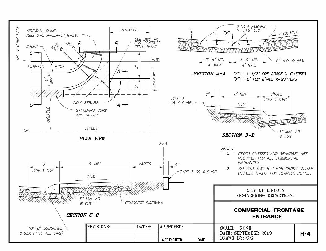
All concrete curbs, sidewalk access ramps, driveways, gutters, island paving, driveways and sidewalks will be installed in accordance with Sections 51 and 73 of the Caltrans Standard Specifications and related Caltrans Standard Plans; the Public Facilities Improvement Standards Details H-1 through H-6;and these standard provisions. All concrete will be designated as Class A "six-sack concrete" unless called out specifically on the approved project improvement plans, where a 28-day minimum compressive strength and/or mix design will be noted. The maximum allowable holding time before concrete placement will be 90- minutes from batch plant to pour. 1. Thickness – All residential and commercial sidewalks adjoining the Curb
and gutter, and meandering bikeways, and/or sidewalks, will be a nominal minimum of 4-inches thick unless they cross commercial driveway locations where they will be a nominal 6-inches thick.
2. Reinforcing – All commercial driveways, including valley gutters and five- foot wide sidewalks in the A-6 driveways, will be a minimum of 6-inches thick, with reinforcement of deformed steel number 4, grade 60 rebar, on 18-inch centers each way as required by City Engineer. Wire for tying reinforcement in place will be No. 18 or heavier, AWG black annealed. Rebar will be set on 2-inch concrete dobies/rebar supports at 3-foot maximum spacing each way. The dobies will have wire ties that will be utilized to anchor the dobies to the rebar. Reinforcement will conform to

PUBLIC FACILITIES SECTION 3 IMPROVEMENT STANDARDS STREETS AND HIGHWAYS
H 15 OF 28
Caltrans Section 52. Any vertical rebar will have exposed ends covered with rebar caps.
3. Finishing – Concrete will not be placed or finished in the rain. It will be
the Contractor's responsibility to schedule construction operations accordingly. Concrete will be cured in accordance with Caltrans Standards Section 90-1.03. All concrete work will be protected against damage and defacement from vandals or during subsequent construction operations. All gutters will be flow tested with water during the pour to assure proper drainage.
All concrete surfaces will be completed with a medium broom finish unless otherwise specified. Surfaces to be used by pedestrian traffic will be broomed transversely to the line of traffic. If water is necessary, the water will be applied to the surface immediately before brooming.
Concrete surfaces will not vary more than 0.02-foot from a 10-foot straightedge, except at grade changes. The finished surfaces will be free from blemishes. Alignment tolerances will be cause for rejection of the work.
4. Sidewalk Access Ramps – The City of Lincoln Public Facilities
Improvement Standards Details H-5, H-5A, H-5B, and H-6 specify standard sidewalk access ramps used in the City. At all locations, sidewalk access ramps will utilize raised truncated domes. The type of sidewalk access ramp, the placement of raised truncated domes, and the scored/grooved sections will be placed as shown on the approved project improvement plans, as required by Title 24 of the Office of the State Architect, as shown in these Public Facilities Improvement Standards Details, and the Caltrans Standard Plans and Standard Specifications.
5. Expansion joints, deep tool joints and score marks – Expansion joints will be the full depth of the concrete and placed at 60 foot intervals, at curb returns in curb, gutter and sidewalk sections, and opposite expansion joints in adjacent curb. All barrier curb and valley gutters will include expansion joints at 60-foot intervals. Expansion joints will be filled with 3/8-inch thick pre-molded joint filler per the Caltrans Standard Specification Section 51-2.01 and ASTM D1751. Refer to Section 3-9 of these Construction Standards for expansion joint filler material requirements. Expansion joint filler will be shaped to fit the concrete that is being placed. Expansion joint material will not be placed against an existing or cured surface, but will only be set with wet concrete on both

PUBLIC FACILITIES SECTION 3 IMPROVEMENT STANDARDS STREETS AND HIGHWAYS
H 16 OF 28
sides. The concrete adjacent to expansion joints will be finished with an edger tool. Deep tool joints and score marks will be placed at these intervals for the sidewalk widths indicated:
Required Spacing for Deep Tool and Score Mark Sidewalk width Deep Tool Spacing Score Mark Spacing
4-feet 12-feet 4-feet 5-feet 10-feet 5-feet 6-feet 12-feet 6-feet 8-feet 8-feet N/A
10-feet 10-feet N/A All deep tool joints will be 1-inch deep. A deep tool joint will be placed at the back of the curb for the total length of all monolithic curb, gutter, and sidewalk. All barrier and median curbs and valley gutters will include deep tool joints at 12-foot intervals.
6. Grades - All sidewalks (including portions through driveways and sidewalk access ramps) will be constructed with a minimum cross slope of 1% and a maximum of 1.5%.
For access ramp landings, the maximum allowable grade is 1% minimum and 1.5% maximum, perpendicular to the street. Parallel to the street, the grade of the landing will conform to the longitudinal grade of the street.
7. Monolithic Sidewalk, Curb and Gutter - When possible, adjoining
sidewalk, curb and gutter will be poured monolithically. When sidewalk, or curb and gutter is being placed against existing sidewalk or curb and gutter, dowels (#4 rebar grade 60, 12-inches long) will be installed at 12-inches on center 4-inches deep on each side.
8. Under Sidewalk Drainage Pipe – 1 1/2-inch or 2-inch PVC pipe may be
placed under the sidewalk surface to carry water from landscape areas to the gutter, when approved by the City Engineer. The discharge end of the pipe will be flush with the face of curb and are only allowed in conjunction with a Type II vertical curb.
9. Curb and Gutter Installation in An Existing Street - In an existing
street, a minimum width of 24-inches of existing asphalt concrete paving will be removed outside the proposed gutter lip and the lip poured against

PUBLIC FACILITIES SECTION 3 IMPROVEMENT STANDARDS STREETS AND HIGHWAYS
H 17 OF 28
a form board. The resulting patch between the gutter lip and the existing pavement will be 6-inches thick, or the thickness of the existing pavement, whichever is greater. If the joint is within 3 feet of a bike lane line or fog line, additional asphalt will be removed to the bike lane line or fog line.
10. Epoxy Work – Where concrete curb is epoxied to a concrete or asphalt concrete surface, a low viscosity paste polysulfide extended epoxy formula is to be used per Caltrans Standard Specification 95. 95% of the surface, below or within the boundaries of the curb, will be coated with this two-part epoxy. If extruded concrete curb is removed for pavement widening, the asphalt concrete pavement will be slurry sealed. Epoxy will be placed in conformance with the Caltrans Standard Specifications Section 95.
11. Median Noses - Median curbs are shown as Type 3 on the Public
Facilities Improvement Standards Detail H-2 Curbs and Gutters. They will have 3 each Type D Pavement Markers - 2-way yellow retroreflective, as specified in Caltrans Specifications Section 85 Pavement Markers. These will be placed onto the face of the curb with the top edge of the Marker one-inch below the top edge of the curb at the mid-point of the curb nose radius and 2-feet left and 2-feet right of mid-point. The Pavement Markers will be cemented to the curb with Standard or Rapid Set Type epoxy adhesive in conformance with the manufacturer's instructions and the Caltrans Specifications Section 95.
H. Asphalt Concrete – Asphalt concrete pavement will be constructed as
required in Section 39 of the either the 2010 or current edition of the Caltrans Standard Specifications and these requirements, as determined by the City Engineer
1. Construction - No prime coat will be required. Tack coat will be applied
between each lift. Lifts placed on the same day will not require tack coating if the surface is not contaminated. All vertical edges of asphalt concrete and concrete facilities such as gutters, cross gutters, swales, etc. will be tack coated. If the tack coat is scraped off or contaminated, it will be reapplied.
The minimum lift thickness will be 1½-inch for ½-inch material and 2¼ inches for ¾-inch material. The finished surface after rolling will be free of coarse and fine pockets. The handwork areas will closely match the texture of the machine laid mat.

PUBLIC FACILITIES SECTION 3 IMPROVEMENT STANDARDS STREETS AND HIGHWAYS
H 18 OF 28
All handwork areas will be compacted concurrently with breakdown rolling. The average finished pavement thickness will be equal to or greater than the design thickness. The minimum pavement thickness will be the design thickness minus 1/4-inch for design pavement thickness of 2-inches or less; minus 3/8- inch for design pavement thickness between 2 and 4-inches; and minus 1/2-inch for pavement thickness of 4-inches or greater. The provisions in Section 39-2.01, "Spreading and Compacting Equipment, of the Standard Specifications will apply. Asphalt Concrete and asphalt concrete base will be compacted to a relative compaction of 96.0 percent. The temperature of the asphalt concrete ready for compaction will not be less than 120-degrees and all breakdown compaction will be completed before the temperature drops to 95-degrees. The atmospheric temperature will be at least 50-degrees to place asphalt concrete. If asphalt concrete base is shown on the plans, the atmospheric temperature will be at least 40-degrees to begin placement.
2. Testing – Asphalt concrete testing will be per the appropriate Caltrans
standard (either current or 2010) as suitable for the pavement design utilized, and also as determined by the City Engineer. The testing requirement listed are therefore the minimum requirements. Asphalt concrete mixture verification tests will be performed at the rate of one set of tests per each 1,000-tons. A minimum of one test for each days paving will be performed. Asphalt concrete for mixture verification tests will be obtained in accordance with CTM 125. The location of each sample will be noted on the test report. The following mixture tests will be performed on each sample: Laboratory Compaction Unit Weight – CTM 304 Hveem Stability – CTM 366 Mix Voids - CTM 367 Layer thickness will be verified either by continuous inspection or by coring. If continuous visual inspection is used, a minimum laydown thickness of 1.25 times the design layer thickness will be used. If verified

PUBLIC FACILITIES SECTION 3 IMPROVEMENT STANDARDS STREETS AND HIGHWAYS
H 19 OF 28
by coring, a randomly selected core for each 2,500-square feet of pavement area with a minimum of 3 for any street segment or cul-de-sac. The minimum compaction at any location will be 96.0%. Compaction will be verified either by nuclear gauge testing. Relative compaction will be determined by CTM 375. One test will be taken for each 2,500-square feet of pavement area with a minimum of 3 tests per street segment. Each street segment may be averaged if the following number of test locations is met:
Pavement Area Number of Tests
0 to 5,000-sf 3 5,001-sf to 10,000-sf 5 10,001-sf to 15,000-sf 8 Over 15,000-sf 10 or 1 per 2,500-sf
If test results in any area fall below the 96.0% minimum requirement by nuclear methods, the results will be verified by cores. Three cores will be taken approximately 10-feet away from the original test location. If the average of these three tests fail to meet the minimum, the pavement area will be cold planed to the depth of the underlying pavement course or aggregate base and will be replaced. If the average pavement compaction fails to meet the 96.0% average requirement by testing using nuclear methods, cores will be taken at each test location and the compaction recomputed. The core test results will govern. If the core average fails to meet the average pavement requirement and the failure is due to one specific area of low test results, this low area will be removed and replaced. If no one distinct area can be isolated, the entire pavement layer will be removed and replaced for the full width of the pavement and to the limits of the failing segment. Areas of coarse handwork or unacceptable joints will be reheated using an infrared heater and reworked until the work complies with these requirements. Skin patching will not be allowed. Existing AC surfaces will be cut to a neat, straight line parallel with the street centerline and the exposed edge will be tacked with emulsion prior to paving. The exposed base material will be graded and recompacted prior to paving.

PUBLIC FACILITIES SECTION 3 IMPROVEMENT STANDARDS STREETS AND HIGHWAYS
H 20 OF 28
I. Raising Iron to Finished Grade – For appurtenances such as manholes and water valves that are in landscape areas, the top elevation/lid of the manhole or valve will be flush with the top of grass or to 1-inch maximum above the top of grass. In landscape areas using bark for cover, the top elevations/lid of that will be 2-inches minimum above the top of bark, to 4-inches maximum above the top of the bark. In concrete or asphalt concrete areas, the iron will be raised to finished grade prior to the final concrete pour, or the last lift of asphalt concrete. If maintenance or warranty work requires repair and/or removal of asphalt concrete around iron appurtenances, the replacement asphalt concrete will be ¾” per Caltrans Specifications.
J. Final Seal Coat in Residential Area – Prior to placement of traffic stripes
and pavement markings, all new public streets will be sealed with a clay- stabilized emulsion designed to seal and protect asphalt pavement. (Refer to Section 3-9 N Materials in these Public Facilities Improvement Standards.) Sealing will be applied after the ambient temperature is 50°F. and rising. Should wet or freezing weather occur within 24-hours following application, the application will be redone. Surface Preparation: All streets to be sealed will be cleaned and all debris will be removed prior to applying seal coat material. Oil spots will be treated with an oil spot primer to insure proper adhesion. All cracks will be blown clean with all debris removed prior to sealing. All cracks greater than ¼-inch wide will be sealed using a hot-applied crack sealant to the level of the adjacent areas. The crack seal material will contain no crumb rubber, and will have a softening point of at least 220°F. All cracks will be blown and cleaned of debris prior to sealing. 3-gallons of an industry-accepted latex such as Henry Duratuff or equal will be added to every 100-gallons of seal coat material directly into the applicator with the agitator running. The seal coat material with latex will be diluted with water at a rate of no more than 15% by volume for a more liquid, spreadable consistency. Once diluted, the material must have constant agitation to avoid separation of reinforcing material. The seal coat product will be applied following the label directions for application. One coat is acceptable on new asphalt surfaces. Two coats will be applied to any street that is over two years old. A two-coat application will require an average of 30-gallons per 1,000-square-feet. The condition of the pavement

PUBLIC FACILITIES SECTION 3 IMPROVEMENT STANDARDS STREETS AND HIGHWAYS
H 21 OF 28
will determine the amount of material needed. For excessively rough areas, the City Engineer may request the addition of three-pounds of 30-mesh or 60-mesh sand to each gallon of Henry #127 DuraSeal.
K. Crack and Joint Sealing – All cracks and joints in asphalt concrete will be filled with Henry #93 DuroFlex (Hot Pour) Asphalt Crack and Joint Sealant or equal following application directions on the product label. (Refer to Materials in these Public Facilities Improvement Standards.)
L. Sound and Retaining Walls & Graffiti Coating – Construction of sound and
retaining walls will conform to the approved project improvement plans for those sound and retaining walls to be owned and/or maintained by City. An anti-graffiti coating will be applied to the City side of all sound and retaining walls bounding the City right-of-way and owned and/or maintained by City. The City Engineer will be furnished a letter certifying that the coating has been applied, as these Public Facilities Improvement Standards require, prior to issuance of the Notice of Completion.
M. Street Barricades – All street and sidewalk barricades will conform to these
Public Facilities Improvement Standards Details H-7, H-8, and H-9, respectively. For additional information, refer to Caltrans Standards Section 83 Railings and Barriers.
N. Street Signs – Street name signs and all other signage will be placed as
shown on the approved project improvement plans, and Public Facilities Improvement Standards Details H-13, H-14, H-15, and H-16. Caltrans Standards Section 56-2 provides additional information.
Street name signs will be 9-inches high, 0.125” thick aluminum, and a minimum of 30-inches long. Panels will have 1/2-inch-rounded comers. The sign attachment will have two 5/16-inch aluminum drive rivets attached through each plate onto the post. The finish will be 3M or equal, VIP grade reflectorized white letters on a reflectorized navy blue background and/or as required by the City. The high intensity reflective sheeting will meet or exceed Caltrans Specifications. The street name letters will be 4-inches high, with the "CITY OF LINCOLN" letters one-inch high, and the street, avenue, etc. in 2-inch high letters. All letters will be upper case. Refer to the Public Facilities Improvement Standards Detail H-13 for exact placement and additional information. (Please refer to the Materials Section in these Public Facilities Improvement Standards for additional information.)

PUBLIC FACILITIES SECTION 3 IMPROVEMENT STANDARDS STREETS AND HIGHWAYS
H 22 OF 28
O. Street Signs Posts – All sign posts will be a square metal tubing conforming to the standard specifications for cold rolled carbon steel, commercial quality, ASTM A446, or hot rolled carbon steel sheet, structural quality ASTM A570-90 & ASTM A653-94 structural grade 50. The steel will be hot dipped galvanized with 1.40-ounces of zinc coating (G-140), conforming to ASTM A653. The square end of the post can be pointed for easy penetration and will be capable of being driven into the ground by the use of an approved driving cap. Corner weld should be zinc coated after scarfing operation. This square post has holes and is coated with a polyester TGIC powder coat in a green gloss finish as supplied by Unit-Strut or Uni-Mate, or equal.
The holes will be 7/16-inches in diameter placed on one-inch centers on all four sides on the centerline for the entire length of the pole. The holes will be in true alignment and opposite each other directly and diagonally. The finished posts will be straight and have a smooth uniform finish. All holes and ends will be free from burrs and the ends will be cut square. Permissible variation in the straightness is 1/16-inch in 3-feet. Square tubes will be installed into a sleeve of the same material. A 30-inch long anchor sleeve will be embedded in Class B/Class 3, 5-sack concrete that is placed in an excavated hole a minimum of 30-inches deep and 6- inches in diameter. Two holes of the sleeve will remain showing above the finished grade, with all holes below grade taped closed. No material other than the square post will intrude into the sleeve. The square signpost inside the sleeve will move freely in the vertical direction after installation. Signs will be securely anchored to the posts with theft-proof bolts, washers, and nuts. 4 x 4 redwood posts are allowable with prior approval of the City Engineer and will conform to Caltrans Specifications Section 56 for redwood posts and will be embedded in Class B, 5- sack concrete which is placed in an excavated hole a minimum of 36-inches deep and 6-inches in diameter. (Please refer to the Materials section in these Public Facilities Improvement Standards for additional information.)
P. Survey Monuments –All street survey monuments will be installed as shown
in Public Facilities Improvement Standard Detail H-24 except as otherwise shown on the approved project improvement plans. Surface monuments will be driven flush with the surface pavement. All lot property comers that are in

PUBLIC FACILITIES SECTION 3 IMPROVEMENT STANDARDS STREETS AND HIGHWAYS
H 23 OF 28
concrete sidewalks will be installed as shown in Public Facilities Improvement Standards Detail H-26 or as indicated on the recorded parcel or final map. All rear lot property corners will be marked with a ½-inch rebar, 12-inches long, and the top flush with finish grade.
3-8 TRAFFIC STRIPES AND PAVEMENT MARKINGS – All traffic stripes and
pavement markings will be installed in accordance with the approved project improvement plans and specifications, Caltrans Standards Sections 84, Caltrans Standard Plans, and the California MUTCD. All traffic str ipes and pavement markings on asphalt concrete will be thermoplastic material and conform to Section 84-2 of the State Standard Specifications. All thermoplastic striping and pavement markings will include glass beads. A. Removal of Existing- Sandblasting of traffic stripes and pavement markings
will not be permitted. Removal will be by grinding, or other methods approved in writing by the City Engineer. A rectangular area will be ground to prevent ghosting of the original markings.
B. Application - To remove all dirt and contaminants, mechanically wire brush existing surface that is to have the thermoplastic material applied. Portland cement pavement will be mechanically wire brushed or abrasive blast cleaned to remove all laitance and curing compound.
C. Thermoplastic material – Thermoplastic material will be applied only to dry
pavement surfaces when the surface temperature is above 65°F / 10°C.
1. The primer recommended by the thermoplastic material manufacturer will be applied to all Portland cement concrete surfaces and all asphalt surfaces over 6-months old. The primer will be applied immediately in advance of, and concurrent with, the application of thermoplastic material. The application rate will be recommended by the primer manufacturer and will not be thinned.
2. Preheaters with mixers having a 360° rotation will be used to preheat the thermoplastic material. The thermoplastic material will be between 392°F/200° C and 428°F/220° C when applied to the pavement, unless the manufacturer recommends a different temperature.
3. The thermoplastic material will be applied by either spray or extrusion methods in a single uniform layer. Unless otherwise specified in special provisions, the thermoplastic material for traffic stripes will be applied at a

PUBLIC FACILITIES SECTION 3 IMPROVEMENT STANDARDS STREETS AND HIGHWAYS
H 24 OF 28
minimum thickness of 0.06-inch/1.5mm. Pavement markings will be applied at a thickness of 0.1 to 0.15-inch/2.5 to 3.8mm. The pavement surface will be completely coated by the material and the voids of the pavement surface will be filled.
4. Glass beads will be applied immediately to the surface of the molten thermoplastic material at a rate of not less than 8.5-pounds/4 kg. Per 100- square feet/10-square meters. The amount of glass beadsꞏ applied will be measured by stabbing the glass bead tank with a calibrated rod.
5. Metal stencils will be used when applying pavement markings. D. Pavement Markers – All non-reflective pavement markers will be ceramic.
Blue reflective markers will be placed on the centerline of any road in line with the fire hydrant location.
Nonreflective Pavement Markers: Use ceramic or plastic nonreflective pavement markers. Nonreflective pavement markers must be free from defects that affect adhesion, appearance, performance, or any combination thereof. The top, bottom, and sides of nonreflective pavement markers must be free from objectionable marks or discoloration. The top surface of nonreflective pavement markers must be convex with a gradual change in curvature. The bottom of nonreflective pavement markers must have areas of integrally formed protrusions or indentations. The bottom surface of the markers must not deviate more than 0.05 inch from a flat surface. The protrusion areas must have faces parallel to the bottom of the marker and must project approximately 0.04 inch from the bottom. When tested under CTM 669, properties of ceramic nonreflective pavement markers must comply with the requirements shown in the following table:
Retroreflective Pavement Markers: The exterior surface of a retroreflective pavement marker shell must be smooth and contain 1 or 2 retroreflective faces of the specified color. The base of a retroreflective pavement marker must be flat, rough textured, and free from gloss and substances that could reduce the adhesive
Test Properties Requirement a Bond strength 700 psi, min b Glaze thickness 0.007 in., min c Hardness 6 Moh, min d Luminance factor, Type A, white markers only, glazed surface 75, min e Yellowness index, Type A, white markers only, glazed surface 7, max f Color-yellow, Type AY, yellow markers only. The chromaticity
coordinates must be within a color box defined in California Test 669 Pass
g Compressive strength 1,500 lb, min h Water absorption 2.0%, max i Artificial weathering, 500 hours exposure, yellowness index 20, max
PUBLIC FACILITIES SECTION 3 IMPROVEMENT STANDARDS STREETS AND HIGHWAYS
H 25 OF 28
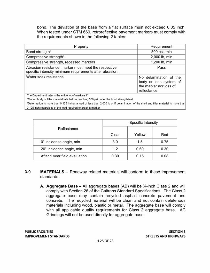
bond. The deviation of the base from a flat surface must not exceed 0.05 inch. When tested under CTM 669, retroreflective pavement markers must comply with the requirements shown in the following 2 tables:
Reflectance
Specific Intensity
Clear
Yellow
Red
0° incidence angle, min 3.0 1.5 0.75
20° incidence angle, min 1.2 0.60 0.30
After 1 year field evaluation 0.30 0.15 0.08
3-9 MATERIALS – Roadway related materials will conform to these improvement standards: A. Aggregate Base – All aggregate bases (AB) will be ¾-inch Class 2 and will
comply with Section 26 of the Caltrans Standard Specifications. The Class 2 aggregate base may contain recycled asphalt concrete pavement and concrete. The recycled material will be clean and not contain deleterious materials including wood, plastic or metal. The aggregate base will comply with all applicable quality requirements for Class 2 aggregate base. AC Grindings will not be used directly for aggregate base.
Property Requirement
Bond strengtha 500 psi, min Compressive strengthb 2,000 lb, min Compressive strength, recessed markers 1,200 lb, min
Abrasion resistance, marker must meet the respective specific intensity minimum requirements after abrasion.
Pass
Water soak resistance No delamination of the body or lens system of the marker nor loss of reflectance
The Department rejects the entire lot of markers if: aMarker body or filler material fails before reaching 500 psi under the bond strength test bDeformation is more than 0.125 inch at a load of less than 2,000 lb or if delamination of the shell and filler material is more than
0.125 inch regardless of the load required to break a marker

PUBLIC FACILITIES SECTION 3 IMPROVEMENT STANDARDS STREETS AND HIGHWAYS
H 26 OF 28
B. Asphalt Concrete – Asphalt concrete will be Type “A” medium gradation. The maximum nominal aggregate size will be ½ inch for residential streets and ½ inch for collectors and arterials.
Asphalt concrete mixtures will meet these requirements in addition to the requirements of Section 39: Mix Voids Residential: 3 – 4.5 % Collector and Arterials: 3.5 – 5% Stability Residential: 35 min. Collector 37 min. Arterials: 40 min. Coarse and Fine Durability 50 min. The Mix Design and Asphalt Concrete “Certificate of Compliance” will be submitted to the designated Geotechnical Engineer for review. The submittal will then be forwarded to the City Engineer for approval.
C. Concrete – All concrete (curbs, gutters, sidewalks, etc) will be Class "A" (equivalent of 6-Sack, 564-pounds of cement per cubic yard mix, Type II) and will conform to provisions in Section 90 of the Caltrans Special Provisions, unless otherwise noted in the Public Facilities Improvement Standards Details. All concrete will be designed for a 28-day minimum compressive strength of 3000- psi.
D. Concrete Additives – Concrete additive will conform to the Caltrans
Standard Specifications and will only be used upon the approval of the City Engineer.
E. Lime – Lime will conform to Section 24 of the State Specifications. F. Truncated Domes – Truncated dome panels will be of vitrified polymer
composite construction, embedded type, manufactured by Armor Tile Tactile Systems, Buffalo, New York, or approved equal. The dimensions and orientation of the truncated domes within the panel will conform to the approved project improvement plans.

PUBLIC FACILITIES SECTION 3 IMPROVEMENT STANDARDS STREETS AND HIGHWAYS
H 27 OF 28
G. Expansion Joiner Filler – The expansion/contraction joint filler will be 3/8-
inch resilient non-extruding cellular fiber joint, uniformly saturated with asphalt, offering a minimum 70% recovery after compression. Joint filler to meet ASTM D1751, such as Sealtight Fibre Expansion Joint as manufactured by W.R. Meadows, Inc. or equal.
H. Graffiti/Anti-Graffiti – The coating will be Prosoco Graffiti Stop, two coat
applications, Krystal Kote, Monochem Perma Shield Graffiti Control or approved equal.
I. Filter Fabric – Geotextile fabric used in trench backfill will conform to State
Specification Section 96 for edge drains. J. Pavement Reinforcing Fabric – Pavement reinforcing fabric will be non-
woven polyester, polypropylene, or polypropylene/nylon materials conforming to these requirements:
ASTM D3776 – Weight, oz/sq. yd 3.0 to 8.0 ASTM D1117 – Grab Tensile Strength (1-inch grab), pounds 90 minutes ASMT D1117 – Elongation at break, percent 40 minutes ASM D461 – Fabric Thickness, mils 12 to 100
K. Controlled Density Fill – Controlled Density Fill will conform to these
requirements:
Mix Components Amounts Volume (cu. Ft.) 28-day comp. Strength 100-psi N/A
Slump 6 to 8-inches N/A Water 292 lbs/yd 4.68
Type 1 Portland Cement
25-pounds 0.13
Class F Fly ash 200-pounds 1.38 Concrete Sand 1442-pounds 8.79
Max 3/8-inch Aggregate 1600-pounds 9.32 Entrained Air 10% ± 3% 2.70
TOTAL MIX VOLUME 27.00

PUBLIC FACILITIES SECTION 3 IMPROVEMENT STANDARDS STREETS AND HIGHWAYS
H 28 OF 28
L. Sign posts/metal – Uni-Strut, Uni-Mate, or equal, are square metal posts
with holes that comply with the specifications. The posts will be produced utilizing a polyester TGIC powder coat in a green gloss. Refer to Public Facility Improvement Standards Detail H-13 and Section 3-7 O for additional information.
M. Pavement Markers – Type D yellow, reflective; Type G clear, reflective; Type
AY yellow, non-reflective as specified in Section 3-8D.
N. Seal Coat – The asphalt-based seal coat material will be manufactured with a clay-stabilization emulsion. Henry #127 DuraSeal or equal will comply with these physical property requirements:
Cone Penetration 350-4450 (ASTM D-217) Residue by Evaporation 60-70 Density 11.0-11.3 pounds per gallon
O. Asphalt Surface Crack and Joint Sealant – The crack and joint sealant
material will contain no crub rubber, and will have a softening point of at least 220̊ F. Henry DuroFlex Crack and Joint Sealant or equal complies with this requirement.
P. Thermoplastic Stripes and Pavement Markings – The thermoplastic
material will conform to either State Specification 8010-01A or 2010-19A. Glass beads will conform to State Specification 8010-004 (Type II).
Q. Backer Rod Specification – Backer rods and proper sealants will conform
to State Specifications 41-5.02D.

PUBLIC FACILITIES IMPROVEMENT STANDARDS
STREETS & HIGHWAYS DETAILS Cross Gutter ..................................................................................... H-1 Curbs & Gutters ............................................................................... H-2 Modified Median Curb Detail ............................................................ H-2A Commercial Driveways Type A-6 ..................................................... H-3 Commercial Frontage Entrance ....................................................... H-4 Sidewalk Ramps for Curbs ............................................................... H-5 Sidewalk Ramps for Curbs ............................................................... H-5A Sidewalk Ramps for Curbs ............................................................... H-5B Typical Sidewalk Ramp Installation for Large Radius Curves .......... H-6 Street Closure Timber Barricade ...................................................... H-7 Signs and Barricades at End of Pavement Widening ...................... H-8 Sidewalk Barricade .......................................................................... H-9 Typical Sections Residential Streets ................................................ H-10 Typical Sections Minor Arterial & Collector Streets .......................... H-11 Typical Sections Major Arterial & Frontage Roads .......................... H-12 Special Sections Street Classes “A”, “B” & “C” ............................... H-12A Street Sign Fully Reflective .............................................................. H-13 Street Name Sign Installation on Street Light Pole .......................... H-14 Street Name Sign Placement Details ............................................... H-15 Street Name Sign Placement on Street Light .................................. H-16 Bus Turnout Details .......................................................................... H-17 Bus Stop ........................................................................................... H-18 Cross Walk / Stop Bar Striping ......................................................... H-19 Site Distance Requirements for 84’ Streets ..................................... H-20 Site Distance Requirements for 94’ Streets ..................................... H-21 Planter and Barrier Curb Detail (A) .................................................. H-21A Alley Details and Driveway Transitions ............................................ H-22 Visibility Requirements Residential Streets ...................................... H-23 Boxed Survey Monument ................................................................. H-24 Utility “T” Trench in Existing Pavement ............................................ H-25 Property Corner Marker Detail ......................................................... H-26 Standard Enclosure for Trash Bin .................................................... H-27 Conduit for Future City Use .............................................................. H-28 Cul-De-Sac Details ........................................................................... H-29 Hammer Head Design ...................................................................... H-30 Planter and Barrier Curb Details ...................................................... H-31 90° Intersection Elbow ..................................................................... H-32 Widening Details at Major Street Intersections ................................ H-33 Commercial Frontage and Driveway Regulations ............................ H-34 Utility Trench Cut-Off Wall ................................................................ H-35

PUBLIC FACILITIES IMPROVEMENT STANDARDS
[THIS PAGE INTENTIONALLY LEFT BLANK]