stratumtm stratumtm duo stratum contour · page 06 stratumtm february - 2014 thermal conductivity...
TRANSCRIPT
STRATUMTM
STRATUMTM DUOSTRATUMTM CONTOURCLADDING SYSTEM
FEBRUARY 2014
WWW.BGCINNOVADESIGN.CO.NZ

INTRODUCING INNOVA™
FEBRUARY 2014
BGC’S STUNNING NEW RANGE OF FACADE, LINING AND FLOORING PRODUCTS, INNOVA™ WILL MOVE YOU TO REASSESS YOUR CONCEPT OF EXCELLENCE IN FACADES AND FLOORING SYSTEMS. DURABLE AND DYNAMIC, FRESH AND CONTEMPORARY, INNOVA™ IS ALREADY TURNING INDUSTRY HEADS. NOW LET THE INNOVA™ RANGE OF CLADDING AND FLOORING PRODUCTS BREATHE NEW LIFE INTO YOUR CREATIVITY AND PROJECT SPECIFICATION.

STRATUMTM IS AN INNOVATIVE TRIO OF PLANK PRODUCTS, EACH OF WHICH CAN BE USED AS STAND ALONE PRODUCTS OR USED TOGETHER TO CREATE A STRIKING EXTERIOR CLADDING SOLUTION
THE 3 PROFILES IN THE STRATUMTM RANGEPROVIDE A MODERN ALTERNATIVE TO TRADITIONAL WEATHERBOARDS.
STRATUMTM IS A 300MM WIDE PLANK WITH A 16MM HORIZONTAL JOINT.
STRATUMTM DUO IS AGAIN A 300MM WIDE PLANK BUT FEATURES A 16MM WIDE GROOVE IN THE CENTRE OF THE PLANK GIVING THE APPEARANCE OF 2 THINNER PLANKS.
STRATUMTM CONTOUR IS A THINNER PLANK BUT FEATURES A 2MM DEEP SHADOWLINEAT THE TOP OF EACH PLANK.
STRATUMTM CLADDING SYSTEM
/ STRATUMTM CLADDING SYSTEM/ AVAILABLE IN 3 STRIKING PROFILES: STRATUM™ (300MM) STRATUM™ DUO (300MM) STRATUM™ CONTOUR (170MM)/ FEATURES AN EASY SHIPLAP JOINING METHOD/ FACTORY SEALED, AND PRIMED READY FOR PAINTING/ QUICK AND EASY TO INSTALL STRATUMTM AND STRATUMTM DUO – ADHESIVE AND BRADS STRATUMTM CONTOUR – MANUAL OR GUN NAILING/ BRANZ APPRAISED
PAGE 03STRATUMTM
FEBRUARY - 2014

CONTENTS
PAGE 04STRATUMTM
FEBRUARY - 2014
PRODUCT DESCRIPTION / 5ADVANTAGES / 5CONTROL OF EXTERNAL FIRE SPREAD / 5 PREVENTION OF FIRE OCCURING / 5PLANK SIZES AND MASS / 5THERMAL CONDUCTIVITY / 6DESIGN CONSIDERATIONS / 6ENERGY EFFICIENCY CONSIDERATIONS / 6WEATHER RESISTANCE/FREEZE THAW / 6CUTTING AND DRILLING / 6 HANDLING AND STORAGE / 6ACCESSORIES AVAILABLE FROM BGC / 7ACCESSORIES SUPPLIED BY BUILDING MERCHANT / 8FASTENERS / 9PLANK COVERAGE / 9FRAMING / 10CAVITY CONSTRUCTION / 10FIXING TO BATTENS / 10INSTALLATION DETAILS / 11-20MOISTURE MANAGEMENT / 21FINISHING / 21MAINTENANCE / 21WARRANTY / 21
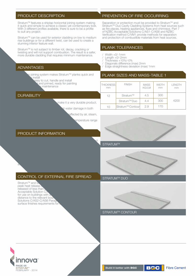
LENGTH mm
THICKNESSmm
12
10
FINISH
StratumTM
StratumTM Duo
StratumTM Contour
WIDTHmm
300
300
170
4200
MASSKG/LM
4.5
4.4
2.9
PAGE 05STRATUMTM
FEBRUARY - 2014
PRODUCT DESCRIPTION
PRODUCT INFORMATION
StratumTM features a shiplap horizontal joining system making it quick and simple to achieve a classic yet contemporary look. With 3 different profiles available, there is sure to be a profile to suit any project.
StratumTM can be used for exterior cladding on low to medium rise buildings or for a different twist, can be used to create a stunning interior feature wall.
StratumTM is not subject to timber rot, decay, cracking or twisting and will not support combustion. The result is a safer, more durable cladding that requires minimum maintenance.
StratumTM is manufactured from Portland cement, finely ground silica, cellulose fibres and water. Planks are cured in a high-pres-sure steam autoclave to create a durable, dimensionally stable product.
StratumTM is manufactured to the Australian / New Zealand Standard AS/NZS 2908.2-2000 Cellulose-Cement Products, Part 2: Flat sheets and StratumTM is classified as Type A-Category 2.
PLANK TOLERANCES
/ Width +0/-1mm/ Length +0/-2mm/ Thickness +10%/-0%/ Diagonals difference (max) 2mm/ Edge straightness deviation (max) 1mm
PLANK SIZES AND MASS-TABLE 1
STRATUMTM
STRATUMTM DUO
STRATUMTM CONTOUR
PREVENTION OF FIRE OCCURRING
Separation or protection must be provided to StratumTM and StratumTM Duo Cavity Cladding Systems from heat sources such as fire places, heating appliances, flues and chimneys. Part 7 of NZBC Acceptable Solutions C/AS1-C/AS6 and NZBC Verification method C/VM1 provide methods for separation and protection of combustible materials from heat sources.
CONTROL OF EXTERNAL FIRE SPREADStratumTM and StratumTM Duo Cavity cladding systems have a peak heat release rate of less than 100kW/m2 and a total heat released of less than 25 MJ/m2. In accordance with NZBC Acceptable Solution C/AS1 Table 5.1 the system is suitable for use on buildings with a SH Risk Group classification, at any distance to the relevant boundary. Refer to NZBC Acceptable Solutions C/AS2-C/AS6 Paragraph 5.8.1 for the specific exterior surface finishes requirements for other building Risk Groups.
DURABILITY
Stratum’sTM physical properties make it a very durable product.
/ StratumTM is immune to permanent water damage in both short and long-term exposure./ StratumTM will not rot or burn and is unaffected by air, steam, salt and sunlight./ StratumTM is not adversely affected over a temperature range of 0°C to 95°C.
ADVANTAGES
/ Shiplap joining system makes StratumTM planks quick and simple to install/ Quick and easy to cut, handle and install/ Acrylic sealed and primed, ready for painting/ Durable and low maintenance

PAGE 06STRATUMTM
FEBRUARY - 2014
THERMAL CONDUCTIVITY
ARCHITECTURAL DETAILS
DESIGN CONSIDERATIONS
WEATHER RESISTANCE/FREEZE THAW
Stratum™ planks have relatively low thermal conductivity. At Equilibrium Moisture content the approximate thermal conductivity of Stratum™ is; - 0.25 W/m°C.
Full architectural details are available from the BGC Fibre Cement NZ website - www.bgcinnovadesign.co.nz or on Productspec and full specification are available on Smartspec.
The designer should determine the wind pressures for the project and design accordingly. Stratum™ can be situated in specific design wind pressures up to a maximum design differential ultimate limit state (ULS) of 2.5kPa.
The timber structure should be designed to NZS3604. Alternatively the building can be to a specific design using NZS3603 and AS/NZS1170, and the framing must be of at least equivalent stiffness to the framing provisions of NZS3604.
In areas where there is a probability of high wind loading, care should be taken in the design detailing, especially around all opening, corners and other junctions to ensure the weather resistance of the total system.
Before Stratum™ is installed, particular care should be taken to ensure that all flashings and waterproofing work is complete, including all wall underlay or BGC Durabarrier. If Stratum™ is installed onto an unlined wall ie gable end or garage walls then a rigid sheathing/air barrier must be installed – ie BGC Durabarrier.
For Construction within the scope of E2/AS1, it is a requirement to have a horizontal flashing joint at the floor joist level between storeys and for construction greater than two storeys or 7 metres, an inter-storey flashing bridging the drained cavity must be installed.
The Stratum™ system has been successfully tested for weather resistance as per NZBC Verification Method E2/VM1.
Stratum™ should not be used in situations where it will be in direct contact with snow and ice for prolonged periods.
StratumTM may be cut to size on site. If using power tools for cutting, drilling or sanding they must be fitted with appropriate dust collection devices or alternatively an approved (P1 or P2) dust mask and safety glasses shall be worn. It is recommended that work always be carried out in a well ventilated location.
The most suitable cutting methods are:
/ DURABLADE 180mm Diameter. This unique cutting blade is ideal for cutting Fibre Cement. Can be fitted to a 185mm circular saw, ie Makita or similar. Please ensure safe working practices when using.
/ NOTCHING Notches can be made by cutting the two sides of the notch. Score along the back edge then snap upwards to remove the notch.
/ DRILLING Use normal high-speed masonry drill bits. Do not use the drill’s hammer function. For small round holes, the use of a hole-saw is recommended. For small rectangular or circular penetrations, drill a series of small holes around the perimeter of the cut out. Tap out the waste piece from the sheet face while supporting the underside of the opening to avoid damage. Clean rough edges with a rasp.
Large rectangular openings are formed by deeply scoring the perimeter of the opening. Next, form a hole in the centre of the opening (refer method above) then saw cut from the hole to the corners of the opening. Snap out the four triangular segments. Clean rough edges with a rasp. (see method above) then saw cut from the hole to the corners of the opening. Snap out the four triangular segments. Clean rough edges with a rasp
CUTTING AND DRILLING
HANDLING AND STORAGE
StratumTM must be stacked flat, up off the ground and supported on equally spaced (max 400mm) level gluts. Care should be taken to avoid damage to the ends, edges and surfaces.
Planks must be kept dry. When stored outdoors it must be protected from the weather. Planks must be dry prior to fixing, jointing or finishing.
ENERGY EFFICIENCY CONSIDERATIONS
Energy Efficiency requirements for both residential and commercial buildings are a requirement under clause H1 of the New Zealand Building Code (NZBC). Thermal heat transfer into and out of the building envelope will affect the running cost of the building and careful consideration of thermal heat transfer needs to be ad-dressed by the architects, engineers and building designers. Thermal bridging through steel framing will diminish the total R-Value (thermal resistance), of the wall. Thermal breaks are required for steel framed buildings and should be installed between the steel framing and the Stratum™ planks. Thermal breaks should have a minimum R-Value of 0.2.Guidance on insulation requirements can be found in the latest edition of BRANZ publication –‘House Insulation Guide’.
PAGE 07STRATUMTM
FEBRUARY - 2014
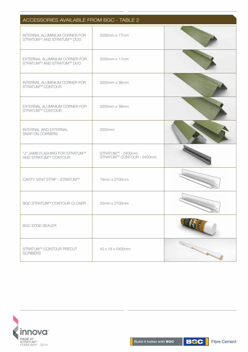
ACCESSORIES AVAILABLE FROM BGC - TABLE 2
INTERNAL ALUMINIUM CORNER FOR STRATUMTM AND STRATUMTM DUO
EXTERNAL ALUMINIUM CORNER FOR STRATUMTM AND STRATUMTM DUO
3000mm x 17mm
INTERNAL ALUMINIUM CORNER FOR STRATUMTM CONTOUR
3000mm x 36mm
3000mm x 17mm
EXTERNAL ALUMINIUM CORNER FOR STRATUMTM CONTOUR
3000mm x 36mm
“J” JAMB FLASHING FOR STRATUMTM AND STRATUMTM CONTOUR
STRATUMTM - 2400mm STRATUMTM CONTOUR - 2400mm
INTERNAL AND EXTERNAL SNAP ON CORNERS
3000mm
40 x 18 x 5400mm
19mm x 2700mm
33mm x 2700mm
BGC EDGE SEALER
STRATUMTM CONTOUR PRECUT SCRIBERS
CAVITY VENT STRIP - STRATUMTM
BGC STRATUMTM CONTOUR CLOSER

SEALANTBostik Safetech Safe Sealor any BRANZ Appraised paintable sealant
SEALANT / ADHESIVE Bostik Seal ‘n’ Flex FC
PAGE 08STRATUMTM
FEBRUARY - 2014
ACCESSORIES SUPPLIED BY BUILDING MERCHANT - TABLE 3
STRUCTURAL CAVITY TIMBER BATTEN H3.1 SG8
20 x 50mm20 x 70mm (for expressed joints inStratumTM and StratumTM Duo).
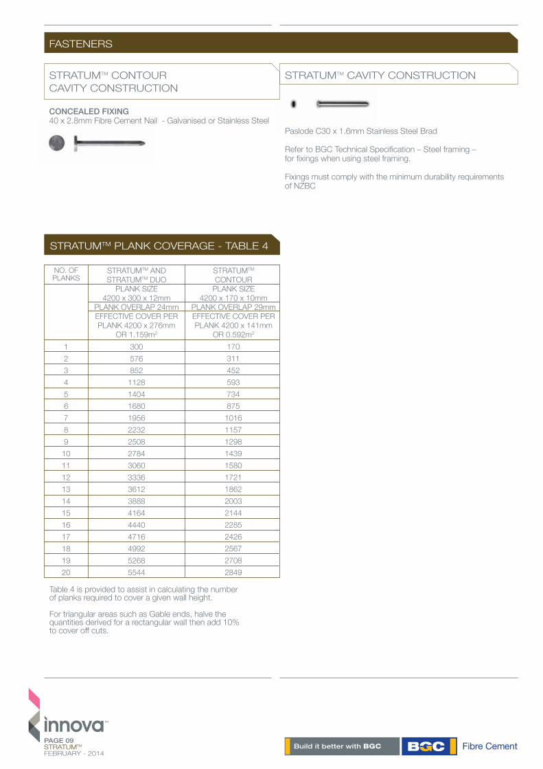
300576852
11281404168019562232250827843060333636123888416444404716499252685544
PAGE 09STRATUMTM
FEBRUARY - 2014
STRATUMTM AND STRATUMTM DUO
PLANK SIZE 4200 x 300 x 12mm
PLANK OVERLAP 24mmEFFECTIVE COVER PER PLANK 4200 x 276mm
OR 1.159m2
STRATUMTM CONTOUR
PLANK SIZE 4200 x 170 x 10mm
PLANK OVERLAP 29mmEFFECTIVE COVER PER PLANK 4200 x 141mm
OR 0.592m2
NO. OFPLANKS
1234567891011121314151617181920
170311452593734875
10161157129814391580172118622003214422852426256727082849
CONCEALED FIXING 40 x 2.8mm Fibre Cement Nail - Galvanised or Stainless Steel
Paslode C30 x 1.6mm Stainless Steel Brad
Refer to BGC Technical Specification – Steel framing – for fixings when using steel framing.
Fixings must comply with the minimum durability requirements of NZBC
STRATUMTM CONTOURCAVITY CONSTRUCTION
STRATUMTM CAVITY CONSTRUCTION
FASTENERS
STRATUMTM PLANK COVERAGE - TABLE 4
Table 4 is provided to assist in calculating the number of planks required to cover a given wall height.
For triangular areas such as Gable ends, halve the quantities derived for a rectangular wall then add 10% to cover off cuts.
STRATUMTM
FIXING C30 304 Stainless Steel Brad – Apply one Brad to the concealed lap section and one brad to the face of StratumTM approximately 50mm from the bottom of the plank. The Brads must be used in conjunction with Bostik Seal ‘n’ Flex FC.
StratumTM must be fixed to the cavity batten with a continuous 6mm bead of Bostik Seal ‘n’ Flex FC to all contact surfaces. The intermediate batten must have 1 x 6mm beads of Seal ‘n’ Flex FC.
A small bead of sealent must be applied to the lap section at the ends of each plank.
Note: Bostik Seal ‘n’ Flex FC must only be applied just prior to the installation of StratumTM Planks as it is a fast cure adhesive.
StratumTM Planks and cavity battens must be dry and free from dust prior to the application of Bostik Seal ‘n’ Flex FC. The adhesive must not be applied in temperatures below 5°.
STRATUMTM CONTOUR
FIXINGStratum™ Contour is concealed fixed with a 40 x 2.8mm Fibre Cement Nail on every stud.
Stratum™ Contour can be joined either on stud or off stud. Off Stud joints must not be closer than 100mm to the edge of the stud and must be staggered by 600mm minimum from the joints in previous courses. A bead of Bostik Seal ‘n’ Flex must be applied to the end of the plank before the corresponding plank is inserted.
A continuous cant strip or profiled packed is required behind the first course of Stratum™ Contour.
The bottom course of Stratum™ Contour must be face fixed to the cavity battens with a 50 x 2.8mm Flat Head Nail 75mm from the bottom of the plank. Pre drilling for the 50 x 2.8mm Nail is recommended. Each subsequent plank is installed with a 40 x 2.8mm Flat Head Nail in the lap. The Nails must be positioned a minimum of 10mm from the plank ends.
It is important that the first course is installed level as it provides a base for all subsequent courses.
The detailed diagrams following are intended to assist the designer in achieving a high quality weather resistant StratumTM installation.
A full range of architectural details are available on bgcinnovadesign.co.nz or from BGC Fibre Cement (NZ).
PAGE 10STRATUMTM
FEBRUARY - 2014
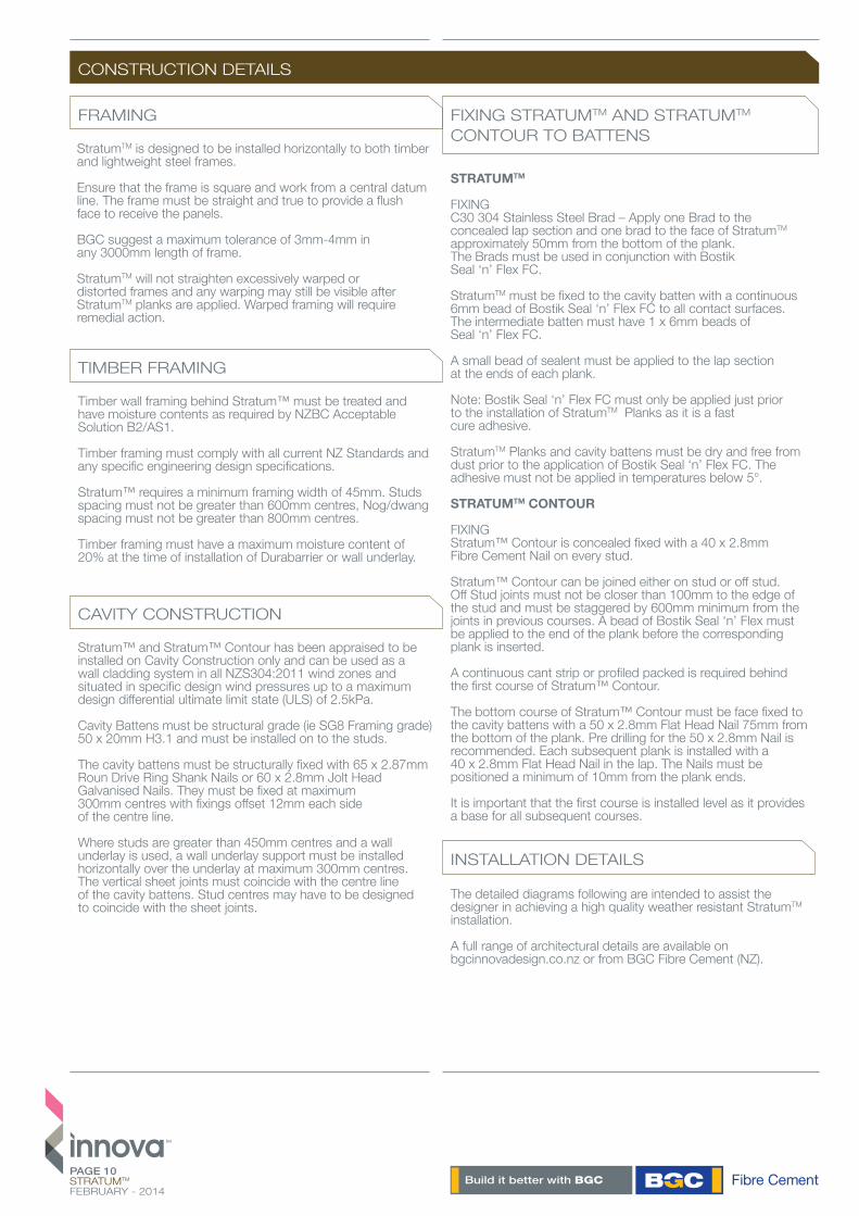
StratumTM is designed to be installed horizontally to both timber and lightweight steel frames.
Ensure that the frame is square and work from a central datum line. The frame must be straight and true to provide a flush face to receive the panels.
BGC suggest a maximum tolerance of 3mm-4mm in any 3000mm length of frame.
StratumTM will not straighten excessively warped or distorted frames and any warping may still be visible after StratumTM planks are applied. Warped framing will require remedial action.
CONSTRUCTION DETAILS
FRAMING
TIMBER FRAMING
INSTALLATION DETAILS
Timber wall framing behind Stratum™ must be treated and have moisture contents as required by NZBC Acceptable Solution B2/AS1.
Timber framing must comply with all current NZ Standards and any specific engineering design specifications.
Stratum™ requires a minimum framing width of 45mm. Studs spacing must not be greater than 600mm centres, Nog/dwang spacing must not be greater than 800mm centres.
Timber framing must have a maximum moisture content of 20% at the time of installation of Durabarrier or wall underlay.
Stratum™ and Stratum™ Contour has been appraised to be installed on Cavity Construction only and can be used as a wall cladding system in all NZS304:2011 wind zones and situated in specific design wind pressures up to a maximum design differential ultimate limit state (ULS) of 2.5kPa.
Cavity Battens must be structural grade (ie SG8 Framing grade) 50 x 20mm H3.1 and must be installed on to the studs.
The cavity battens must be structurally fixed with 65 x 2.87mm Roun Drive Ring Shank Nails or 60 x 2.8mm Jolt Head Galvanised Nails. They must be fixed at maximum 300mm centres with fixings offset 12mm each side of the centre line.
Where studs are greater than 450mm centres and a wall underlay is used, a wall underlay support must be installed horizontally over the underlay at maximum 300mm centres. The vertical sheet joints must coincide with the centre line of the cavity battens. Stud centres may have to be designed to coincide with the sheet joints.
FIXING STRATUMTM AND STRATUMTM CONTOUR TO BATTENS
CAVITY CONSTRUCTION
PAGE 11STRATUMTM
FEBRUARY - 2014
INSTALLATION DETAILS
FIGURE 1 CONSTRUCT FRAME
Wall Underlay
Ensure required ground clearance provided
PAGE 12STRATUMTM
FEBRUARY - 2014
INSTALLATION DETAILS
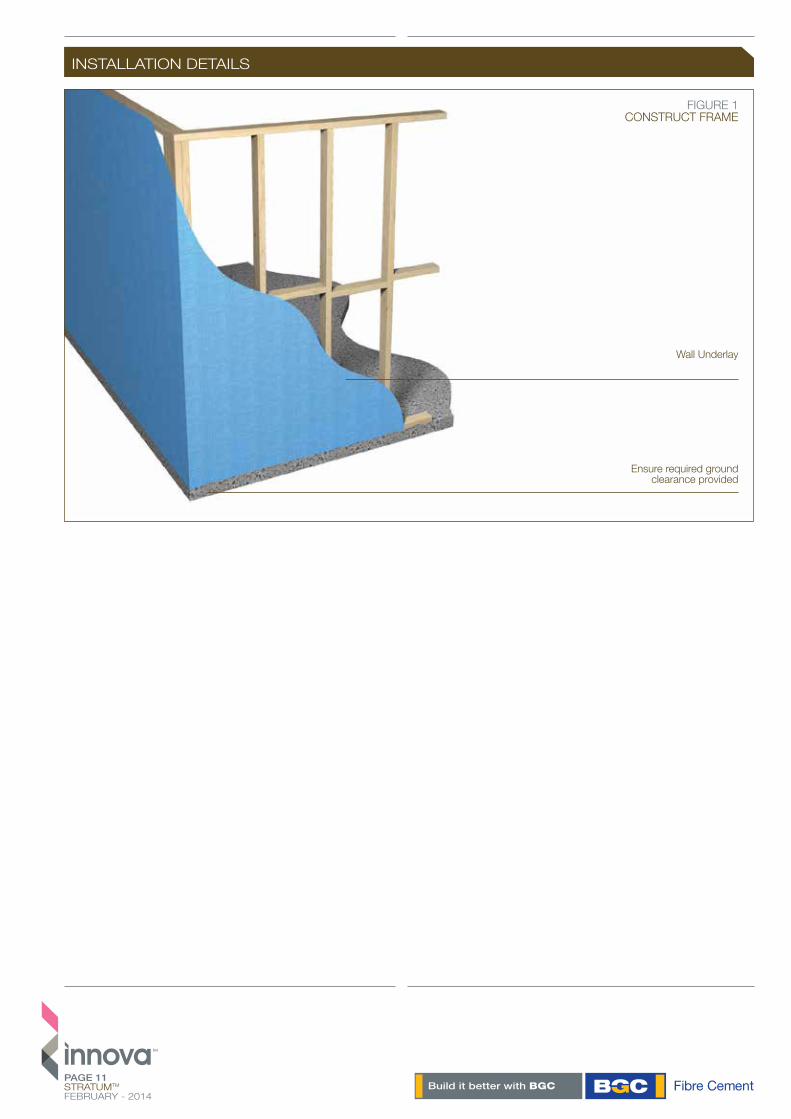
FIGURE 2 STRATUMTM CONTOUR SLAB DETAIL
40 x 2.8mm Fibre Cement Nail
Cavity Batten
StratumTM Contour
StratumTM Contour Closer
Wall Underlay
Continuous Cant Strip or Profiled Packer
FIGURE 3 STRATUMTM AND STRATUMTM DUO SLAB DETAIL
30 x 1.6mm C Series Stainless Steel Brad
50mm
100mm min to paving or 175mm to unprotected ground
Cavity Batten
Wall Underlay
6mm bead of Bostik Seal ‘n’ Flex
StratumTM

PAGE 13STRATUMTM
FEBRUARY - 2014
INSTALLATION DETAILS
6mm Bead of Bostik Seal ‘n’ Flex
Cavity Batten
Wall Underlay
6mm Bead of Bostik Seal ‘n’ Flex
FIGURE 5 STRATUMTMAND STRATUMTM DUO ON STUD JOINTING
30 x 1.6mm C Series Stainless Steel Brad
Vapour Permeable Sarking
FIGURE 4 STRATUMTM CONTOUR ON STUD JOINTING
Wall Underlay40x2.8mm Fibre Cement Nail
Cavity Batten
Bead of Bostik Seal ‘n’ Flex
18mm
StratumTM Contour
StratumTM
PAGE 14STRATUMTM
FEBRUARY - 2014
INSTALLATION DETAILS
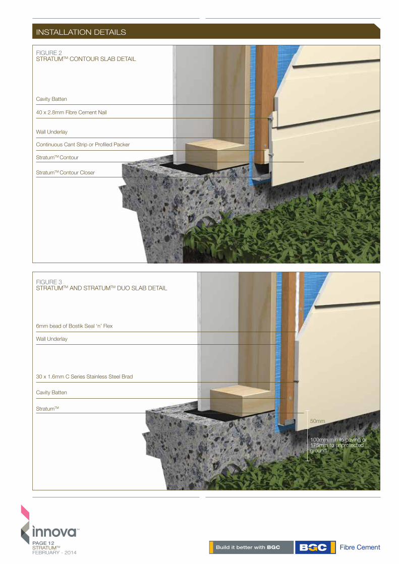
FIGURE 6 STRATUMTM CONTOUR OFF STUD BUTTED JOINT
Wall Underlay
Cavity Batten
40x2.8mm Fibre Cement Nail
Bead of Bostik Seal ‘n’ Flex
FIGURE 7 STRATUMTM AND STRATUMTM DUOON STUD JOINTING
6mm Bead of Bostik Seal ‘n’ Flex
Cavity Batten
Wall Underlay
30 x 1.6mm C Series Stainless Steel Brad
2-3mm Bead of Sealant
StratumTM Contour
StratumTM
PAGE 15STRATUMTM
FEBRUARY - 2014
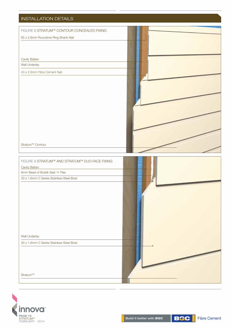
INSTALLATION DETAILS
FIGURE 9 STRATUMTM AND STRATUMTM DUO FACE FIXING
StratumTM
30 x 1.6mm C Series Stainless Steel Brad
30 x 1.6mm C Series Stainless Steel Brad
Wall Underlay
6mm Bead of Bostik Seal ‘n’ FlexCavity Batten
FIGURE 8 STRATUMTM CONTOUR CONCEALED FIXING
StratumTM Contour
Cavity Batten
65 x 2.8mm Roundrive Ring Shank Nail
Wall Underlay
40 x 2.8mm Fibre Cement Nail
PAGE 16STRATUMTM
FEBRUARY - 2014
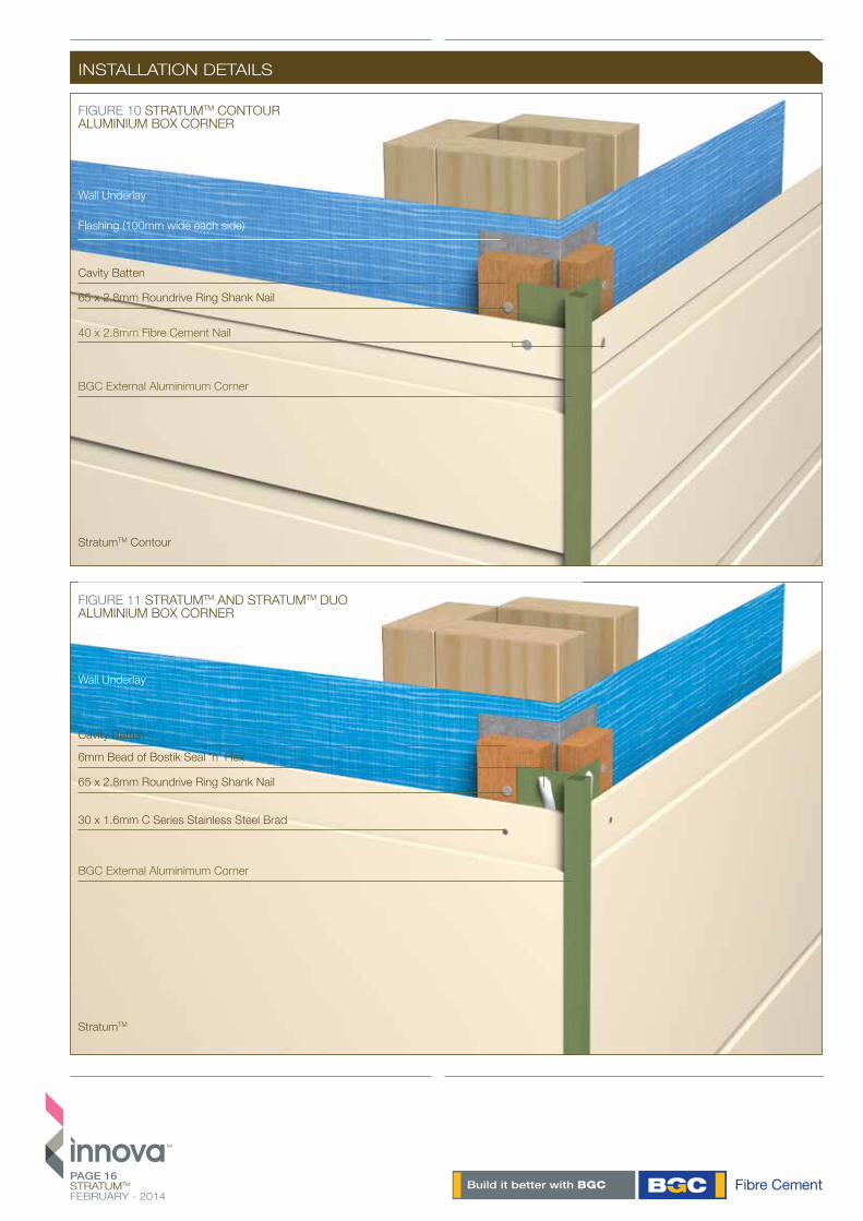
FIGURE 10 STRATUMTM CONTOURALUMINIUM BOX CORNER
FIGURE 11 STRATUMTM AND STRATUMTM DUO 14ALUMINIUM BOX CORNER
Wall Underlay
Wall Underlay
Flashing (100mm wide each side)
BGC External Aluminimum Corner
40 x 2.8mm Fibre Cement Nail
BGC External Aluminimum Corner
65 x 2.8mm Roundrive Ring Shank Nail
Cavity Batten
65 x 2.8mm Roundrive Ring Shank Nail
Cavity Batten
6mm Bead of Bostik Seal ‘n’ Flex
30 x 1.6mm C Series Stainless Steel Brad
StratumTM Contour
StratumTM
INSTALLATION DETAILS

PAGE 17STRATUMTM
FEBRUARY - 2014
INSTALLATION DETAILS
FIGURE 13STRATUMTM AND STRATUMTM DUO
INTERNAL CORNER ALUMINIUM W INTERNAL CORNER
FIGURE 12STRATUMTM CONTOUR INTERNAL CORNERALUMINIUM W INTERNAL CORNER
Cavity Batten
Cavity Batten
40 x 2.8mm Fibre Cement Nail
30 x 1.6mm C Series Stainless Steel Brad
BGC Internal Corner
BGC Internal Corner
Wall Underlay
Wall Underlay
Flashing (100mm wide each side)
6mm Bead of Bostik Seal ‘n’ Flex
Flashing (100mm wide each side)
65 x 2.8mm Roundrive Ring Shank Nail
StratumTM Contour
StratumTM

PAGE 18STRATUMTM
FEBRUARY - 2014
INSTALLATION DETAILS
FIGURE 14STRATUMTM CONTOUR WINDOW HEAD
FIGURE 15STRATUMTM AND STRATUMTM DUO WINDOW HEAD
StratumTM Contour
StratumTM
Aluminium Head Flashing with 15o fall
Aluminium Head Flashing with 15o fall
Wall Underlay
Wall Underlay
BGC Contour Closer
BGC Contour Closer
Cavity Batten
Cavity Batten
Continuous Cant Strip or Profiled Packer

PAGE 19STRATUMTM
FEBRUARY - 2014
INSTALLATION DETAILS
FIGURE 16STRATUMTM CONTOUR WINDOW SILL
FIGURE 17STRATUMTM AND STRATUMTM DUO WINDOW SILL
StratumTM Contour
StratumTM
Wall Underlay
Air Seal over Backing Rod
Sill Support Bar
Timber Packer
Foam Seal
Cavity Batten
30 x 1.6mm C Series Stainless Steel Brad
Wall Underlay
Air Seal over Backing Rod
Sill Support Bar
Timber Packer
Cavity Batten
40 x 2.8mm Fibre Cement Nail

TM
PAGE 20STRATUMTM
FEBRUARY - 2014
INSTALLATION DETAILS
FIGURE 18STRATUMTM CONTOUR JAMB DETAIL
FIGURE 19STRATUMTM AND STRATUMTM DUO JAMB DETAIL
Wall Underlay
Wall Underlay
Air Seal over Backing Rod
Air Seal over Backing Rod
Cavity Batten
Cavity Batten
BGC J Flashing
BGC J Flashing
Foam Seal
Foam Seal
Aluminium Window Joinery
Aluminium Window Joinery
Timber Packer
Timber Packer
StratumTM Contour
StratumTM

TM
PAGE 21STRATUMTM
FEBRUARY - 2014
MOISTURE MANAGEMENT
MAINTENANCE
WARRANTY
FINISHING
Designers, specifiers and builders have a duty of care to identify moisture-associated risks with any individual building design.
Wall construction design should consider both the interior and exterior environments of the building to effectively manage moisture. Special consideration should be given to buildings that are in extreme climates or at higher risk of wind driven rain.
In addition, all wall openings, penetrations, junctions, connections, window heads, sills and jambs must incorporate appropriate flashing for waterproofing. All other components, materials and installation methods used to manage moisture in walls should comply with the relevant standards of the New Zealand Building Code.
Building owners are responsible for the maintenance of Stratum™ cladding systems. The maintenance requirements should be determined by the specifier based on the location and exposure of the building.
It is recommended that
/ Regular cleaning at least annually of the paint finish with water and a mild detergent/ Do not water blast/ Inspect regularly and repair if required/ Check ground clearances/ Follow paint manufacturer’s recommendations on recoating
BGC Fibre Cement (NZ) warrants its products to be free from defects caused by defective materials or workmanship (manufac-turer) for a period of 15 years from the date of purchase, subject to the conditions set out below. Further, BGC Fibre Cement (NZ) warrants its products to be resistant from rotting, fire and cracking so long as the installation is carried out in accordance with BGC Fibre Cement literature available at the time of purchase.i) This warranty is non transferable.ii) The product must be installed and maintained in accordance with the relevant BGC Fibre Cement (NZ) literature current and available at the time of purchase. All additional products including acces-sories, jointing systems and coatings used in conjunction with the BGC Fibre Cement product(s) must be applied or installed according to the appropriate manufacturer’s instructions.iii) BGC Fibre Cement (NZ) is not liable for any breach of warranty unless the claimant provides proof of purchase and a claim is submitted in writing within 30 days of the defect becoming evident. If the defect is detected prior to installation, the claim must be submitted before installation occurs.iv) If BGC Fibre Cement (NZ) products are found to be defective, BGC Fibre Cement will at its option, repair or replace the product, supply equivalent replacement products or reimburse the purchase price of the product.v) BGC Fibre Cement (NZ) shall not be liable for any damage or losses (direct or indirect) including property damage or personal injury, economic loss or loss of profits, consequential loss arising in contract or negligence or howsoever arising.
BGC Fibre Cement (NZ) shall not be liable for any claims, damages or defects arising from or attributed to poor workman-ship, poor design or detailing, settlement or structural movement or movement of materials to which the product is attached, incorrect design of the structure, acts of God, including but not limited to floods, cyclones, earthquakes or severe weather or unusual climate conditions, performance of coatings or paints applied to the product, normal wear and tear, growth of mould, mildew, fungi, bacteria or any other organism on the products surface (exposed or unexposed).
vi) The project must be designed and constructed in accordance with all relevant requirements of the current New Zealand Building Code regulations and standards.vii)If satisfying a claim under this warranty which involves recoating or painting of BGC Fibre Cement (NZ) products, there may be slight colour differences between the replacement product and the original products due to the effect weathering and variations in materials over time.viii) All warranties, conditions, liabilities and obligations other than those specified in this warranty are excluded to the fullest extend allowed by the law.
DISCLAIMER
The successful performance of the relevant product depends on a number of factors outside the control of BGC Fibre Cement (NZ). As such, BGC Fibre Cement (NZ) shall not be liable for the recommendations made in its literature and the performance of the products/systems including its suitability for any purpose or ability to comply with the relevant conditions set out in the NewZealand Building Code. It is the responsibility of the building designer to ensure that the details and recommendations provided in the relevant BGC Fibre Cement (NZ) installation guide are suitable for the intended project and that specific design is conducted where appropriate.
The instructions and recommendations in BGC Fibre Cement (NZ) literature are based on good building practice, but are in no way an exhaustive statement of all relevant information and are subject to conditions above. BGC Fibre Cement has tested the performance of its products when installed in accordance with the products technical specification, in accordance with the standards required by the New Zealand Building Code. Those test results demonstrate the products compliance with the performance criteria set out by the New Zealand Building Code.
Painting of Stratum™ is required to meet the durability and the external moisture management of the NZBC and BGC Warranty.
Stratum™ must be painted within 90 days of installation.
Stratum™ panels must be clean, dust free and dry before painting.
If the BGC Aluminium corner has been used, Stratum™ can be painted a dark colour.
Brad heads must be flush with the sheet surface and skimmed with a suitable exterior 2 part builder’s filler. The skimmed area should be spot primed.
BGC recommends that Stratum™ is coated with a quality undercoat and minimum of two coats of high build acrylic paint. Refer to the paint manufacturer’s recommendations for specific details.

TM
PAGE 22STRATUMTM
FEBRUARY - 2014
NOTES

TM
PAGE 23STRATUMTM
FEBRUARY - 2014
NOTES
WWW.BGCINNOVADESIGN.CO.NZDESIGN WWW.THESHAPEGROUP.COM.AUDESIGN WWW.THESHAPEGROUP.COM.AU
BGC FIBRE CEMENT IS A PROUD AUSTRALIAN OWNED MANUFACTURER OF FIBRE CEMENT PRODUCTS.
BGC FIBRE CEMENT PROVIDES BUILDERS, DEVELOPERS AND ARCHITECTS WITH A RANGE OF DESIGN ALTERNATIVES AND INNOVATIVE PRODUCTS, SUCH AS:
EXTERIOR PRODUCTS AND APPLICATIONSINNOVA RANGE OF PRODUCTS
DURACOMTM / A compressed fibre cement facade system.DURAFLOORTM / Is the ultimate flooring product that can used in both interior and exterior applications. DURAGRIDTM RESIDENTIAL & DURAGRIDTM LIGHT COMMERCIAL / A light weight facade giving a modern and durable finish.DURAGROOVETM / A vertically grooved exterior facade panel.DURASCAPETM / A lightweight exterior facade base sheet with a subtle vertical shadow line. NULINETM PLUS / A weatherboard style cladding system.STONESHEETTM / Purpose designed substrate for stone tile facade. STRATUMTM / Is a trio of plank products, each of which can be used as stand alone products or used together to create a striking exterior cladding solution.
EXTERIOR PRODUCTS AND APPLICATIONSBGC FIBRE CEMENT RANGE OF PRODUCTS
DURASHEETTM / Ideal for the cladding of gables and lining of eaves. Can also be used on commercial soffits and cladding on non impact areas.DURAPLANKTM / Available in Smooth, Woodgrain and Rusticated finishes, DuraplankTM is ideal for exterior cladding of upper storey conversions or ground level extensions.DURALATTICETM / Square or diamond patterned lattice, suitable for screens, pergolas and fences.COMPRESSED / Used for domestic, commercial sheet for wet areas, flooring, partitions, exterior decking, fascia and facade cladding.DURALUXTM / Suitable for exterior applications where it will be sheltered from direct weather.
INTERIOR PRODUCTS AND APPLICATIONSBGC FIBRE CEMENT RANGE OF PRODUCTS
DURALUXTM / An interior lining board suitable for ceilings and soffits.DURALINERTM / An interior lining board, this is the perfect substrate for tiles and is ideal for wet areas.CERAMIC TILE UNDERLAY / A substrate for ceramic and slate floor tiles.VINYL CORK FLOOR COVERINGS / A substrate for vinyl floors.
CONTACT
BGC FIBRE CEMENTPO BOX 76695MANUKAU CITY 2241
TELEPHONE / 09 264 1457FREE PHONE / 0800 424234FACSIMILE / 09 264 1459
WWW.BGCINNOVADESIGN.CO.NZ