strategy of an integrated limiter design for eu-demo first
TRANSCRIPT

Strategy of an integrated limiter design for
EU-DEMO first wall protection from plasma
transient events
F. Maviglia,
G. Federici, M. Siccinio, R. Ambrosino, R. Bonifetto, G. Calabrò, R. De Luca, E.Fable, P. Fanelli, A. Fanni, M. Firdaouss, J. Gerardin, R. Lombroni, G. Maddaluno,M. Moscheni, F. Palermo, G. Pautasso, S. Pestchanyi, G. Ramogida, M. L.Richiusa, G. Sias, F. Subba, F. Villone, Z. Vizvary, WPPMI collaborators

Outline
• Introduction: ITER and DEMO heat load requirements
• First wall protection from plasma transients
1) Plasma transient identification
2) Plasma simulations
3) 3D heat flux (HF) calculations ↔ Limiters surface design
4) Thermal calculations
5) Limiters design
• Conclusions
Francesco Maviglia | IAEA Technical Meeting on Plasma Disruptions and their Mitigation | Virtual | 20-23 July 2020 | Page 2

KDII1: ITER and DEMO heat load requirements
“enhanced” heat flux technology
“normal” heat flux technology
ITER: • FW has no tritium breeding requirements.• A large fraction of ITER’s Cu-alloy first-wall can be
designed for up to ~5 MW/m2. (CuCrZr has extremely high K~300 W/mK but irradiation lifetime of only ~10 dpa)
DEMO:• Tritium breeding: FW with thin layer of materials.• DEMO FW structural material: EUROFER
(much lower thermal conductivity K~30 W/mK,but high irradiation lifetime) Steady state heat loads limited to ~1-2 MW/m².
• W armour (high melting point) conducts heat to the heat sink overheating the cooling channels, evaporation only at very high T poor resistance against heat load transients.
W (2mm)
EUROFER(2-3mm)
Coolant He/H2O high press/temp
bree
ding
zon
e
First wall - breeding blanket
R. Mitteau, JNM 2011
ITER conformal wall: precision required difficult to achieve with DEMO ≈9m tall BB segments
Present ITER SS limit up to 4.7MW/m2: DEMO (~1-2 MW/m²)load specification developed independently
Francesco Maviglia | IAEA Technical Meeting on Plasma Disruptions and their Mitigation | Virtual | 20-23 July 2020 | Page 3

EU-DEMO FW protection from plasma transients
Design, performance and feasibility of wall protection limiters during plasma transients
Transient identification:• transport simulations
• ITER HNLS
•Experimental (JET, AUG,
TCV, EAST)
Electromagn. sim.:•2D/3D EM models
•Closed loop sim.
•Magnetic + kinetic (ongoing)
3D Heat Flux calc.:•Charged particles•Radiation loads •Misalignment, e-folding length sensitivity studies
Limiters shaping:•shape + protrusion•poloidal location•number
Thermal calc./PFC des.: •1.5D/3D
•Vapour shielding
•Runaway electrons (REs)
•Advanced Materials
Limiter design:• Integration
•Remote maintenance
• Inspection
•TBR
1) 2) 3a)
3b)4)5)
Francesco Maviglia | IAEA Technical Meeting on Plasma Disruptions and their Mitigation | Virtual | 20-23 July 2020 | Page 4
Design process:

Plasma transient identification
Several activities launched to predict possible contact points:
Transport simulations (ASTRA code) to evaluate plasma perturbations (Δβpol, Δli, ΔIp)
Inter-machine perturbation database: JET, ASDEX, EAST, TCV (ongoing)
ITER Heat and Nuclear Load Specifications: e.g. U/D-VDE, unmitigated/mitigated disruptions
Experimental database, JET, ASDEX, EAST, TCV: H-L, L-H ELMs Minor disruption SN/DN
Synthetic (ASTRA) database,perturbations generated for: Loss of confinement ntm—like W influx H2O influx ELM like Minor disruption TQ interm. timesc. (conserv.)
Synthetic Experimental (Ongoing)
IPP
Univ: Cagliari/Tuscia
Francesco Maviglia | IAEA Technical Meeting on Plasma Disruptions and their Mitigation | Virtual | 20-23 July 2020 | Page 5

Plasma simulations: Electromagnetic model
3D code CARMA0NL (computationally expensive), and 2D codes CREATE-NL and
MAXFEA codes. 2D equivalent structures and vacuum vessel tuned on 3D model features
(e.g. vacuum vessel ports, non toroidally continues breeding blanket and divertor). The more
precise and faster 2D simulations used to predict possible plasma-wall impact locations
These codes are benchmarked with each other and experimentally.
.
CREATE-NL MAXFEA
2D, with 3D corrections3D
CARMA0NL
Francesco Maviglia | IAEA Technical Meeting on Plasma Disruptions and their Mitigation | Virtual | 20-23 July 2020 | Page 6
F. Villone et al. 2018 EPS
S.L. Chen, et al. NF 2019 R. Albanese, et al. 2019 FED P. Barabaschi, 1993 Naka

3D HF calculations and limiter surface design
Plasma ramp-up/down assumed [0.1; 0.2]MA/s. λq = 6mm, Psol[MW] = Ip[MA] assumption (ITER like) RU: x-point formation in range at [3.5; 6]MA: tRU= 18 to 60s
Misalignments may be reduced if limiter adjustable at OMP port. Bare wall HF ≈3-4MW/m2
No relevant HF found on other BB modules, nor on the limiter during flat-top phases
Max HF = 3.5MW/m² (ITER rescale)
RU: Limited eq. 6MA, #4 OML
PSOL = 6MW λq = 6mm
RU: 18-35s,
2-5MW/m2
Normal transients: ramp-up/down on Outer Midplane Limiter (OML)
PFCFlux
Loss of confinement: Conservative
case on Inner Midplane Limiter (IML)
#4 IML used to
prevent FWdamages during TQ
Preliminary
engineering design: HF≥40MW/m2
Off-normal transients
Francesco Maviglia | IAEA Technical Meeting on Plasma Disruptions and their Mitigation | Virtual | 20-23 July 2020 | Page 7
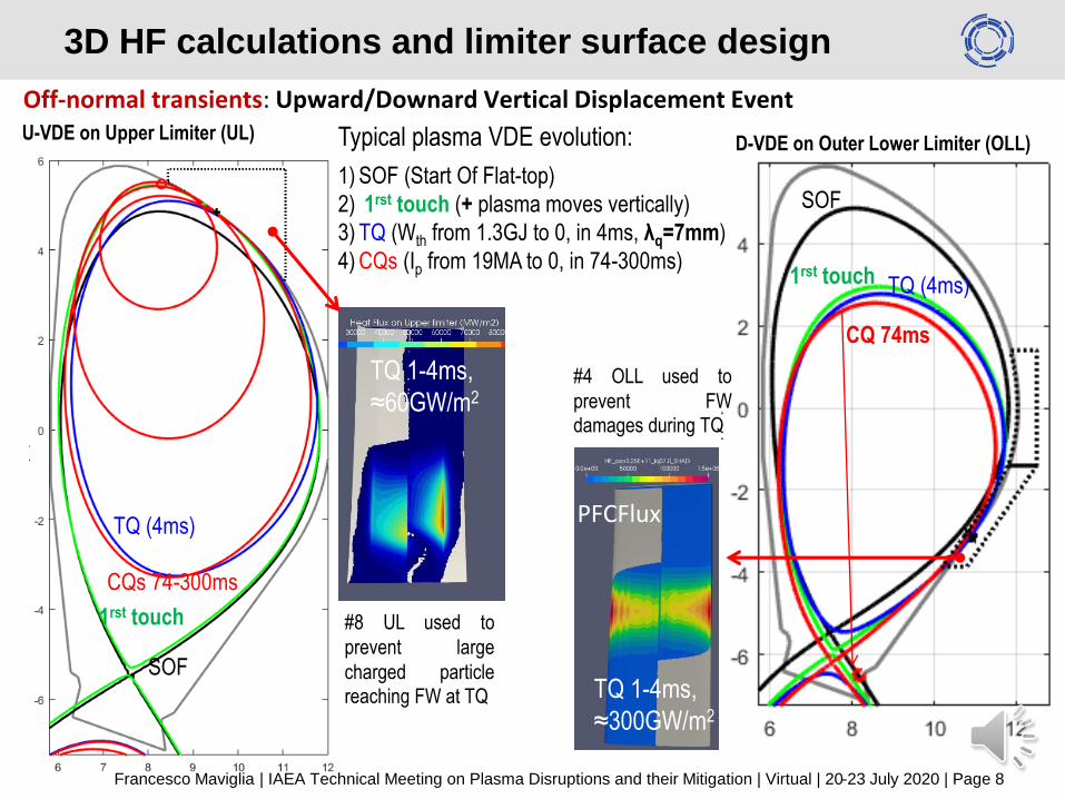
Off-normal transients: Upward/Downard Vertical Displacement Event
SOF
1rst touch
TQ (4ms)
CQs 74-300ms
3D HF calculations and limiter surface design
SOF
1rst touch TQ (4ms)
CQ 74ms
TQ 1-4ms,
≈300GW/m2
D-VDE on Outer Lower Limiter (OLL)
PFCFlux
TQ 1-4ms,
≈60GW/m2
#8 UL used to
prevent large
charged particlereaching FW at TQ
#4 OLL used to
prevent FWdamages during TQ
U-VDE on Upper Limiter (UL) Typical plasma VDE evolution:
1) SOF (Start Of Flat-top)
2) 1rst touch (+ plasma moves vertically)
3) TQ (Wth from 1.3GJ to 0, in 4ms, λq=7mm)
4) CQs (Ip from 19MA to 0, in 74-300ms)
Francesco Maviglia | IAEA Technical Meeting on Plasma Disruptions and their Mitigation | Virtual | 20-23 July 2020 | Page 8

Preliminary results: Mitigated Major Disruption or U-VDE : Initial thermal energy Wth=1.3GJ: 20% radiated at pre-TQ at MGI/SPI: remaining ≈ 1GJ At TQ ITER aims at radiating 80% in 1-3ms (controllable) -> Prad≈800GW
Calculations on TQ mitigated disruption started (mainly based on ITER HNLS scaling)
If Tor. & Pol. peak. fact.(TPF)*=2.8, for Prad = 800GW (hence Prad =
2.2TW ) → max HF ≈ 2GW/m2
W EUROFER
time:RACLETTE 1GW/m2 for 3ms, on H2O FW:
80% radiation in 3ms may be above FW W-limit
TQ radiation time may be slowed down with MGI/SPI
Mitigation techniques to consider FW damages (limiters ineffective)
Cooling pipe below limits
(W/m²)
≈30µm molten W
W-surface
Radiation during mitigated disruptions
CHERAB, ENEA-PoliTo
Francesco Maviglia | IAEA Technical Meeting on Plasma Disruptions and their Mitigation | Virtual | 20-23 July 2020 | Page 9
Input: Prad = 500GW
Output: Max HF ≈0.41GW/m2
*ITER uses TPF= 1.8 (tor.) and 1.5-4.5 (pol.).

3D HF calculations and limiter surface design
Inputs for: 3D field-line tracing charged particle HF (PFCflux, SMARDDA)Scenario (main
limiter)Case(s) PSOL (MW) λq (mm) Deposition time (s)
SOF/EOF (all) Diverted 69 50 Steady state
Min. disr. & ELM (all) Diverted 69 50 15 – 50 ms
Ramp-Up (OML) Limited 3.5 6 17.5 - 35
Ramp-Down (OLL) Limited5
6 25 - 5050 25 - 50
7.56 37.5 - 75
50 37.5 - 75
U-VDE (UL)
unmitigated
First touch 691 20 – 35 ms5 20 – 35 ms
TQ 325GW 7 1 - 4 ms
CQ1 & CQ2 1010 74 – 200 ms30 74 – 200 ms
D-VDE (OLL)
unmitigated
First touch 691 15- 35 ms5 15 - 35 ms
TQ 325GW 7 1 - 4 ms
CQ1 & CQ2 1010 74 – 200 ms30 74 – 200 ms
H-L transition (IML)Limited
(inboard)30
2 1 - 54 1 - 5
Inputs for: 3D radiation HF (CHERAB)Case PSOL (MW) Deposition time (s)
Mitigated disruption (all)
Mitig. - TQ 800GW 1-3 ms
Outputs: max HF (MW/m2)On limiters (ρ-
rescaled)On FW (ρ-rescaled)
2.11 0.67
1.31 1.48 (1)
2.40 0.32
3.61 04.51 0.474.19 03.14 0.42
100 (5) 015.9 0.04
58,800 (6) 286 (2)
4.68 0.056.07 0.22
623 (7) 051.8 (8) 0
300,000 (9) 5.9 (3)
10.8 019.2 0.14
39.56 (10) 0.1214.78 1.81
Outputs: max HF (MW/m2)On limiters & FT, with TPF 2.8
≈3,000-1,000 (4)
DEMO essential requirement to operate minimizing disruptions.All considered perturbations and relative HF on limiters and FW:
critical cases in redPreliminary misalignment studies ongoing for penalty factors.
Francesco Maviglia | IAEA Technical Meeting on Plasma Disruptions and their Mitigation | Virtual | 20-23 July 2020 | Page 10

•All heat sink below limits
Thermal calculations
RACLETTE code used to quickly simulate thermal behaviour of PFC designs:
BB FW simplified model Sacrificial limiter model Divertor like limiter model
H2O coolant, EUROFER heat-sink H2O coolant, CuCrZr heat-sink H2O coolant, CuCrZr heat-sink
Coolant parameters:Vel = 8m/sPres = 15 MPaT_coolant = 300°C
Coolant parameters:Vel = 8m/sPres = 5 MPaT_coolant = 160°C
Coolant parameters:Vel = 8m/sPres = 5 MPaT_coolant = 160°C
Case W-Evap. (µm) W-Melt. (µm) Heat sink temp. (°C)First Wall (EUROFER limit 550°C)(1)Control. Pert. 0 0 394(2) U-VDE TQ 0 0 448(3) D-VDE TQ 0 0 384(4) Mitig. Disr. 0 38 545Sacrificial limiter: (CuCrZr limit 350°C)(4) Mitig. Disr. 0 38 172(5) U-VDE 1st touch 0 0 171(6) U-VDE TQ 2560 988 176
(7) D-VDE 1st touch 82 698 179
(8) D-VDE 1st touch 0 0 171
(9) D-VDE TQ Not converged
(10) H-L conservative 120 3470 280Divertor like limiter: (CuCrZr limit 350°C)(4) Mitig. Disr. 0 23 184
RACLETTE is conservative when W vaporisation ≥tens µm: possible mitigation from vapour shielding
1
1
2
3
2 3
•FW armour protected, mitig. disr., to be tuned
t1=2.5mm
t2=20mm
28mm
W
H2O Ø=12mm
w=7mm
h=7mm
t1=2-3mm
H2O
EUROFER
W
CuCrZr pipe 1.5mm
Cu interlayer 1mmt2=2mm
13.5mm
t1=2.5mmt2=8mm
28mm
W
H2O Ø=12mm
CuCrZr pipe 1.5mm
Cu interlayer 1mm
Francesco Maviglia | IAEA Technical Meeting on Plasma Disruptions and their Mitigation | Virtual | 20-23 July 2020 | Page 11
•For VHHF sophisticated codes are being used

Vapor shielding model in Major Disruption
With shieldingWithout shielding
Preliminary simulations including vapor shielding have been performed on DEMO using TOKES code on:Major (Central) Disruption (plasma in diverted configuration):• Thermal quench duration 4ms• Charged particles energy = 0.65GJ (1/2 EKIN_tot) (to 1.3GJ)
Inne
r st
rike
Out
er s
trik
e
Inne
r st
rike
Out
er s
trik
e
Colors represent
different instants
from 1 to 10ms
With vapor shielding factor 10 reduction in Qwall (from 25 GW/m2 to 2.5 GW/m2).
Max vaporization is reduced from 700μm (in line with RACLETTE▲) to 4μm, melting from 400μm to 150μm
Preliminary results. In line with ITER modelling [1] and (old) exp. Validation [2]
[1] S.Pestchanyi, et al., FED, vol. 109, p. 141, 2016
[2] S.Pestchanyi, et al., FED, vol. 124, p. 401, 2017
S. Pestchanyi, et al., FST (2019)
S. Pestchanyi, et al., NME (2020)
DEMO-TOKES
Francesco Maviglia | IAEA Technical Meeting on Plasma Disruptions and their Mitigation | Virtual | 20-23 July 2020 | Page 12
Further DEMO experimental validation requested in QSPA

Armour R&D
Francesco Maviglia | IAEA Technical Meeting on Plasma Disruptions and their Mitigation | Virtual | 20-23 July 2020 | Page 13
Heat Flux Reduction
I. Prompt vapour shielding
II. Acceptable thermal
conductivity
III. High S/V ratio
Longer lifetime
I. Less thermal stress and
more ductile behaviour
II. Avoid overloading of the
heat sink
III. Hindered crack propagation
Ongoing activities:
Different geometries samples production
Microscopic inspection
Material characterization (density, thermal diffusivity, mechanical
testing)
Plasma compatibility and H-retention tests
HHF experiments on linear plasma devices (QSPA Kh-50)
FEM-based tools for thermal simulation with melting /
vaporization
W lattice: tailored metamaterial designed to get desired
characteristics and realized in additive manufacturing
Radiating Source
CuCrZr Heat sink(water cooled)
W lattices(target)
10
1.5
Sacrificial limiter as the last protection resource of the reactor wall
e.g.: Anisotropy A=0.5
Constant profile ligament
ligament length L=0.33mm
ligament radius section R=0.15mm
Relative density 53.3%
Thermal Condutivity 48.8 W/mK
QSPA Kh-50

Runaway Electrons preliminary calculations
The FLUKA code [1-3] is used to estimate the REs energydeposition profile for different PFC. Simplified assumptions:
• REs current = 4MA (EU-DEMO max curr. =20MA),
• e- energy 20MeV (mono-energetic), incidence angle α=[1,10]˚
• RRE=9m, aRE=1.5m (1/2 of pl.), cross section 7m;
Beam duration: wide range: A)1ms (EKIN= 15MJ), B) 100ms (≈CQtime EKIN + EMAG = 305MJ ). C) Conservative τ=16μs (EKIN= 1.3GJ)
Francesco Maviglia | IAEA Technical Meeting on Plasma Disruptions and their Mitigation | Virtual | 20-23 July 2020 | Page 14
[1] T. Böhlen, et al., "The FLUKA Code: Developments and Challenges for High Energy and Medical Applications“ Nuclear Data Sheets 120, 211-214 (2014)
[2] A. Ferrari, et al."FLUKA: a multi-particle transport code“, CERN-2005-10 (2005), INFN/TC_05/11, SLAC-R-773
[3] G. Maddaluno et al., “Energy deposition and thermal effects of runaway electrons in ITER-FEAT plasma facing components” JNM (2003)
[4] Y. Igitkhanov, B. Bazylev, S. Pestchanyi, “EFFECT OF RUNAWAY ELECTRONS ON THE DEMO WALL EROSION”, ICFRM-(2019).
FLUKA: single
20MeV e−
energy
deposition in thedivertor (α= 10°,BT = 5.8 T)
Input table used to run FEM analysis of PFCs (with W armor 8 and 20mm).
No cooling pipe melting observed in sim. (with present assumptions)
FLUKA being benchmarked with stopping power (ESTAR), and MEMOS-ENDEP[4]
GeV/cm3 (per e-)
Heat load per unit
surface for cases A,
B, C, rescaling
FLUKA

1) #8 Upper Limiters (UL), designed for U-VDE.2) #4 Outboard Lower Limiters (OLL), designed for D-VDE.3) #4 Inboard Mid-plane Limiters (IML), designed for H-L
transitions, and in general for all the events characterizedby a sudden loss of the plasma confinement energy.
4) #4 Outboard Mid-plane Limiters (OML), designed forplasma ramp up and down.
#4 OML:Ramp Up/ down: 18-
60s, 2-5MW/m2
#4 OLL D-VDE:
TQ 1-4ms, ≈300GW/m2
#4 IML H-L :
1-5s,≈15-40MW/m2
#8 UL U-VDE :
TQ 1-4ms,≈60GW/m2
Vert.
instab.
Confinement.
loss
Sketch of proposed limiter locations. Arrows
indicate plasma movement due to vertical
instability (up/down), and loss of energy
(inwards)
Two types of limiters areproposed:1. Sacrificial limiters (for the
others) with 20mm W- armorfor very high ≈0.1-100GW/m2 up to ≈100ms
2. Divertor-like (for OML), fornormal transients RU/RD(tens of seconds and up toten MW/m2):
Limiters design
Francesco Maviglia | IAEA Technical Meeting on Plasma Disruptions and their Mitigation | Virtual | 20-23 July 2020 | Page 15

DEMO requirements are different from ITER: wall load specification being
developed independently.
Present DEMO first wall heat load limits of 1MW/m2
Radiation and charged particles heat loads are evaluated, and four poloidal
location proposed for limiters (divertor-like and sacrificial).
Proposed discrete limiters able to protect the BB FW in all the considered
cases. Some requirements are needed on the mitigated disruptions.
Misalignment studies started on Limiters and FW.
More sophisticated simulations (e.g. vap. shielding, REs), and hardware R&D
and testing proposed for proposed PFC.
Limiter design and integration initiated
Conclusions
Francesco Maviglia | IAEA Technical Meeting on Plasma Disruptions and their Mitigation | Virtual | 20-23 July 2020 | Page 16
Thank you for your attention!

DEMO Static loads: Conservative – Psep slow transient
Conservative, R. Wenninger, NF 2017
Radiation loads: CHERAB code using Core (ASTRA) + SOL (SOLPS) photonic radiation
Charged particles: PFCflux/SMARDDA 3D field-line tracing
codes
Core
SOL
Blobs
Francesco Maviglia | IAEA Technical Meeting on Plasma Disruptions and their Mitigation | Virtual | 20-23 July 2020 | Page 17
(backup slide)

Results : SOF, Total heat flux
Total HFFar SOL Charged particles HFRadiative HF: CORE+SOL
3D HF maps produced (and continuously updated) with WPBB, and WPDIV for FW + Limiterdesign
No HFat 11o’clockNor IB
J. Gerardin(IPP.CZ), M. Firdaouss(CEA)
• Maximum total heat flux located on upper limiter : 1.1MW/m²• Module 7-8 shadowed from charged particles HF by limiter, and upper x-point rotation
Francesco Maviglia | IAEA Technical Meeting on Plasma Disruptions and their Mitigation | Virtual | 20-23 July 2020 | Page 18
(backup slide)

Plasma simulations: control loop
Definition of disruption cases, and relative inputs, e.g.:
• perturbation time evolution Bpol, Li, Ipla
• Control perturbations
• Electromagnetic simulations
• 2D heat flux (HF) calculation of radiated and charged particle
• Plan to use realistic diagnostics from end 2019
WPDC-PMI WPMAG-PMI WPBoP
WPDC
(Ongoing)
PMIWPPMI
E.g.: control simplified scheme
2D/3D
Francesco Maviglia | IAEA Technical Meeting on Plasma Disruptions and their Mitigation | Virtual | 20-23 July 2020 | Page 19
(backup slide)

Energy density [MJ/m2]– deposition time [ms] maps
Case W-Evap. (µm) W-Melt. (µm) Heat sink temp. (°C)Sacrificial limiter: (CuCrZr heat sink temp. lim. 350°C)(4) Mitig. Disr. 0 38 172(5) U-VDE 1st touch 0 0 171(6) U-VDE TQ 2560 988 176
(7) D-VDE 1st touch 82 698 179
(8) D-VDE 1st touch 0 0 171
(9) D-VDE TQ Not converged(10) H-L conservative 120 3470 280
RACLETTE is conservative when W vaporisation ≥tens µm: possible mitigation from vapour shielding F. Maviglia | KDII#1 Review | Garching | 22-23 October 2019 | Page 20
Example: Sacrificial limiter
E[MJ/m2]/τ[ms] scan created for each PFC, to quickly assess vap./melt./temp./CHF
▲▲-TOKES
equivalent,
next page
▲
(backup slide)

Preliminary misalignment studies
Francesco Maviglia | IAEA Technical Meeting on Plasma Disruptions and their Mitigation | Virtual | 20-23 July 2020 | Page 21
Components
LOB -20 -10 10 20 -20 -10 10 20
COB -20 -10 10 20 -20 -10 10 20
ROB -20 -10 10 20 -20 -10 10 20
LIB -20 -10 10 20 -20 -10 10 20
RIB -20 -10 10 20 -20 -10 10 20
LOB -20 -10 10 20 -20 -10 10 20
COB -20 -10 10 20 -20 -10 10 20
ROB -20 -10 10 20 -20 -10 10 20
LIB -20 -10 10 20 -20 -10 10 20
RIB -20 -10 10 20 -20 -10 10 20
OML -5 -2 2 5 -5 -2 2 5
UL -10 -5 -2 2 5 10
OLL -10 -5 -2 2 5 10
Component
Test Matrix
RU (PSOL=3.5 [MW] - lq=6 [mm])
Rigid radial translation [mm] Rigid radial translation [mm]
SOF (PSOL=69 [MW] - lq=50 [mm])
Rigid vertical translation [mm] Rigid vertical translation [mm]
Rigid radial translation [mm] Rigid radial translation [mm]
Rigid radial translation [mm]
Flexible deformations [mm]
TBD
Rigid radial translation [mm]
Vertical/radial misalignment studies ongoing to evaluate penalty factors (= HF misaligned/HF nominal):• First wall: ±20mm, ±10mm (Left/Central/Right Outer, & Left Right Inner Blanket)• OLL and UL: ±10mm, ±5mm, ±2mm.• OML: ±5mm, ±2mm.
CCFE/EEG M.L. Richiusa
TB presented @ SOFT 2020
Limiters shadow FW in critical areas (close to 2nd inactive x-point, & baffles) also in SOF/EOF (DEMO plasma-FW clearance ≥23 cm)
Misalignments mainly affects limiter edge exposure to HF
Limiter protrusion (chosen at the moment for FW protection) can be revised if BB tolerances require it. Flexible deformation ongoing. Example of penalty
factors for limiters
(backup slide)

Equatorial Port Limiter (Outboard Limiter)
MOVEMENT TILTING
Radial – YES Radial axis – NO
Vertical – NO Vertical axis – NO
Toroidal – NO Toroidal axis – YES
Hinge
Lifetime limit 2.75 dpa / 6 fpy in VV around the limiter confirmed by MCNP < 0.5 dpa / 6 fpy
From 6 degrees of freedom, 2 are needed:
a) Limiter port plug inside EQ portb) Limiter port plug + closure plate
TF coil heating <50W/m3 MCNP
• Radial protrusion to FW 2 cm (at assembly in Port Plug under B-field) with radial alignment from control room without physical access requirement of alignment +/-3 mm variation with 0.2 mm precision!
• Actuators by spring + He-filled bellow w/o motor!
Design for replacement of PFCs together with shield block, and reuse of Port Plug
Right TF coil Win-ding Pack
Left TF coilWP
Courtesy: Ch. Bachmann, Th. Franke, R. Mozzillo, A. Cufar
(backup slide)
Francesco Maviglia | IAEA Technical Meeting on Plasma Disruptions and their Mitigation | Virtual | 20-23 July 2020 | Page 22

TBR preliminary estimation with limiters(backup slide)
Present preliminary assumptions: : The change of the neutron spectrum also in the BB due to the presence of water in the limiters is not considered in this simple estimate and will be assessed by Pavel Pereslavtsev in 2019.16 equatorial and 16 upper port plugs. In addition 4 top limiter, 4 inboard limiters, 4 lower inboard limiters, and 8 lower outboard limiters
The change of the neutron spectrum also in the BB due to the presence of water in the limiters is not considered in this simple estimate and will be assessed by Pavel Pereslavtsev in 2019.
Required TBR of hypothetical blanket configuration dependent on:
TBR requirement for final BB design configuration, see previous req., i.e. 1.05
Assumed fraction of FW not covered by BB, i.e.:
Component Surface
8 upper port plugs, ~1.0 m² each 8 m²
3 NB ducts, ~1.3 m² each 4 m²
4 EC launchers, ~4 m² each 16 m²
5 Diag. plugs, ~4 m² each 20 m²
Total 1 48 m²
4 equat. limiters, ~3m² each 12 m²
8 upper port limiters, ~4.5 m² each 36 m²
4 inboard limiters, ~2.5 m² each 10 m²
4 lower mid-plane limiters, ~3 m² each
12 m²
Total 2 70 m²
Total 1 + Total 2 118 m²
FW surface area (excl. BB penetrations): 1473 m².
Non-breeding fraction = 118/1473=8.0% TBR increase factor = 1.087. required TBR =
1.087*1.05 = 1.14
Francesco Maviglia | IAEA Technical Meeting on Plasma Disruptions and their Mitigation | Virtual | 20-23 July 2020 | Page 23

3D HF calculations and limiter surface design
Plasma ramp-up/down assumed from +0.1 MA/s up to + 0.2 MA/s. λq = 6mm, Psol[MW] = Ip[MA] assumption (ITER like) RU: x-point formation in range at 3.5MA to 6MA: tRU= 18 to 60s RD: x-point kept down range 7.5MA – 5 MA: tRD = 20s to 80s
Misalignments may be reduced if limiter adjustable at OMP port. Bare wall HF ≈3-4MW/m2
No relevant HF found on other BB modules, nor on the limiter during flat-top phases
Max HF = 3.5MW/m² (ITER rescale)
RU: Limited eq. 6MA, 4 limiters
PSOL = 6MW λq = 6mm
RD: 25-60s,
2-5MW/m2
RD: Limited eq. 5MA, 4 limiters
RU: 18-35s,
2-5MW/m2
Normal transients: ramp-up/down
PFCFlux PFCFlux
Francesco Maviglia | IAEA Technical Meeting on Plasma Disruptions and their Mitigation | Virtual | 20-23 July 2020 | Page 24
(backup slide)

Off-normal transients: Upward Vertical Displacement Event and scenario optimization
SOF
1rst touch
TQ (4ms)
CQs 74-300ms
Baseline
•1rst touch close or at 11 ‘O
clock
•CQ ends up at 11 ‘O clock
Typical plasma VDE evolution:
1) SOF (Start Of Flat-top)
2) 1rst touch (+ plasma moves vertically)
3) TQ (Wth from 1.3GJ to 0, in 4ms)
4) CQs (Ip from 19MA to 0, in 74-300ms)
+
+
Optimised scenario
•1rst touch ,TQ and CQ
moved towards upper port
area.
Obtained by moving upper
x-point clockwise (reduced
upper-triangularity, δ95%
from 0.33 to 0.25)
SOF
1rst touch
TQ (4ms)
CQs 74-300ms
Off-normal transients: Unmitigated VDE
Francesco Maviglia | IAEA Technical Meeting on Plasma Disruptions and their Mitigation | Virtual | 20-23 July 2020 | Page 25
(backup slide)

Off-normal trans.: Downward-VDE and conservative loss of confinement
SOF
1rst touch TQ (4ms)
CQ 74ms
•1rst touch right below OMP at
4 ‘O clock, Far from baffle
•TQ shrinks plasma which
become diverted again.
Event: TQ intermed.
time-scale
Plasma shapes:
Flat-top
0.6s after event
1.2s after event
TQ 1-4ms,
≈300GW/m2
1-5s,≈15-
40MW/m2
Loss of confinement:
Conservative caseD-VDE (unmitigated)
None on the presently
considered loss of confinement
leads to inboard plasma contact:
conservative case chosen
deliberately above limits
3D HF calculations and limiter surface design
PFCFlux
PFCFlux
Francesco Maviglia | IAEA Technical Meeting on Plasma Disruptions and their Mitigation | Virtual | 20-23 July 2020 | Page 26
Preliminary
engineering design: HF≥40MW/m2
(backup slide)

Results : SOF, Total heat flux
Total heat fluxCharged particles heat fluxRadiative heat flux
• Maximum total heat flux located on upper limiter : 1.1MW/m²• Module 7-8 shadowed from charged particles HF by limiter, and
upper x-point rotation
F. Maviglia | WPBB review | 27 May 2020 | Page 27
(backup slide)