strategy module fm458/cmc 930 - bosch-industrial.com.au · strategy module fm458/cmc 930 6 720 803...
TRANSCRIPT

Strategy module
For contractors
FM458/CMC 930Read carefully prior to
commissioning or service.Service instructions
6 72
0 80
3 19
6(2
011/
06)
GB
/ IE
/ A
U

2 |
1 Safety . . . . . . . . . . . . . . . . . . . . . . . . . . . . . . . . . . . . . . . . 5
1.1 About these instructions . . . . . . . . . . . . . . . . . . . . . . . . . 5
1.2 Determined use . . . . . . . . . . . . . . . . . . . . . . . . . . . . . . . 5
1.3 Standards and directives . . . . . . . . . . . . . . . . . . . . . . . . . 5
1.4 Explanation of the symbols used . . . . . . . . . . . . . . . . . . . . 6
1.5 Observe this information . . . . . . . . . . . . . . . . . . . . . . . . . 6
1.6 Disposal . . . . . . . . . . . . . . . . . . . . . . . . . . . . . . . . . . . 8
2 Product and function description. . . . . . . . . . . . . . . . . . . . 9
2.1 Front panel . . . . . . . . . . . . . . . . . . . . . . . . . . . . . . . . . .11
2.2 Switch on the module PCB . . . . . . . . . . . . . . . . . . . . . . . .122.2.1 Module recognition switch . . . . . . . . . . . . . . . . . . . . . . .122.2.2 Voltage/current output . . . . . . . . . . . . . . . . . . . . . . . . .14
2.3 Terminology key . . . . . . . . . . . . . . . . . . . . . . . . . . . . . .152.3.1 EMS boiler . . . . . . . . . . . . . . . . . . . . . . . . . . . . . . .152.3.2 CAN boiler . . . . . . . . . . . . . . . . . . . . . . . . . . . . . . .152.3.3 Mixed cascade . . . . . . . . . . . . . . . . . . . . . . . . . . . . .152.3.4 Series operation. . . . . . . . . . . . . . . . . . . . . . . . . . . . .162.3.5 Parallel operation . . . . . . . . . . . . . . . . . . . . . . . . . . . .172.3.6 Boiler sequence . . . . . . . . . . . . . . . . . . . . . . . . . . . . .182.3.7 Load limit . . . . . . . . . . . . . . . . . . . . . . . . . . . . . . . .20
3 Installation . . . . . . . . . . . . . . . . . . . . . . . . . . . . . . . . . . . .23
3.1 Scope of supply . . . . . . . . . . . . . . . . . . . . . . . . . . . . . . .23
3.2 Checking the software versions . . . . . . . . . . . . . . . . . . . . .24
3.3 Installation in the CFB 930 control unit . . . . . . . . . . . . . . . . .24
3.4 Connecting inputs and outputs . . . . . . . . . . . . . . . . . . . . .25
3.5 Connecting sensors . . . . . . . . . . . . . . . . . . . . . . . . . . . .26
3.6 Connecting EMS boilers . . . . . . . . . . . . . . . . . . . . . . . . . .27
3.7 Assigning the boiler number . . . . . . . . . . . . . . . . . . . . . . .28
3.8 Recommended hydraulic schemes . . . . . . . . . . . . . . . . . . .323.8.1 CAN boiler via low loss header . . . . . . . . . . . . . . . . . . . . .343.8.2 EMS boiler via low loss header . . . . . . . . . . . . . . . . . . . . .363.8.3 EMS boiler with EMS DHW . . . . . . . . . . . . . . . . . . . . . . .383.8.4 CAN boilers in series . . . . . . . . . . . . . . . . . . . . . . . . . .403.8.5 CAN boilers in parallel . . . . . . . . . . . . . . . . . . . . . . . . .423.8.6 CAN boilers in "Tichelmann System" . . . . . . . . . . . . . . . . . .44
6 720 803 196 (2011/06) FM458/CMC 930 Strategy module

| 3
3.8.7 Twin-block boiler according to the "Tichelmann principle" . . . . . . . 463.8.8 Mixed cascade via low loss header . . . . . . . . . . . . . . . . . . 483.8.9 System with different EMS boilers . . . . . . . . . . . . . . . . . . . 50
4 Integrating EMS boilers . . . . . . . . . . . . . . . . . . . . . . . . . . . 52
4.1 Base controller BC15 . . . . . . . . . . . . . . . . . . . . . . . . . . . 52
5 Functions of the FM458/CMC 930 . . . . . . . . . . . . . . . . . . . 55
5.1 Operation with Programmer . . . . . . . . . . . . . . . . . . . . . . . 55
5.2 Integrating function module FM458/CMC 930 in the control unit . 565.2.1 Integrate function module FM458/CMC 930 on Programmer level. . . 565.2.2 Integrate function module FM458/CMC 930
manually on Programmer level . . . . . . . . . . . . . . . . . . . . . 56
6 General specification data. . . . . . . . . . . . . . . . . . . . . . . . . 58
6.1 0 – 10 V input . . . . . . . . . . . . . . . . . . . . . . . . . . . . . . . . 58
6.2 Temperature control 0 – 10 V input . . . . . . . . . . . . . . . . . . . 60
6.3 Output control for 0 – 10 V input . . . . . . . . . . . . . . . . . . . . 62
7 Strategy data . . . . . . . . . . . . . . . . . . . . . . . . . . . . . . . . . . 66
7.1 Number of boilers . . . . . . . . . . . . . . . . . . . . . . . . . . . . . 66
7.2 Maximum system temperature. . . . . . . . . . . . . . . . . . . . . . 67
7.3 Hydraulic decoupling . . . . . . . . . . . . . . . . . . . . . . . . . . . 68
7.4 Boiler sequences . . . . . . . . . . . . . . . . . . . . . . . . . . . . . . 69
7.5 Sequence switching . . . . . . . . . . . . . . . . . . . . . . . . . . . . 727.5.1 "Sequence revers. none" . . . . . . . . . . . . . . . . . . . . . . . . 737.5.2 Sequence reversal subject to hours run . . . . . . . . . . . . . . . . 747.5.3 Sequence reversal subject to outside temperature. . . . . . . . . . . 767.5.4 "Sequence revers daily" . . . . . . . . . . . . . . . . . . . . . . . . 787.5.5 "Sequence reverse external contact" . . . . . . . . . . . . . . . . . . 79
7.6 Load limit . . . . . . . . . . . . . . . . . . . . . . . . . . . . . . . . . . 807.6.1 Load limit according to outside temperature . . . . . . . . . . . . . . 817.6.2 Load limit via external contact . . . . . . . . . . . . . . . . . . . . . 847.6.3 Operating mode serial / parallel . . . . . . . . . . . . . . . . . . . . 857.6.4 Lead boiler run-on time (pump/servomotor) . . . . . . . . . . . . . . 867.6.5 Lag boiler run-on time (pump/servomotor) . . . . . . . . . . . . . . . 87
6 720 803 196 (2011/06)FM458/CMC 930 Strategy module

4 |
8 DHW data . . . . . . . . . . . . . . . . . . . . . . . . . . . . . . . . . . . . .88
8.1 Selecting the DHW cylinder . . . . . . . . . . . . . . . . . . . . . . . .88
8.2 Setting the temperature range . . . . . . . . . . . . . . . . . . . . . .91
8.3 Selecting switching optimisation . . . . . . . . . . . . . . . . . . . .92
8.4 Selecting residual heat use . . . . . . . . . . . . . . . . . . . . . . . .93
8.5 Setting hysteresis. . . . . . . . . . . . . . . . . . . . . . . . . . . . . .95
8.6 Selecting and setting up thermal disinfection. . . . . . . . . . . . .97
8.7 Setting the thermal disinfection temperature . . . . . . . . . . . . .99
8.8 Setting the day of the week for thermal disinfection . . . . . . . . 100
8.9 Setting the time for thermal disinfection . . . . . . . . . . . . . . . 101
8.10 Daily heat-up . . . . . . . . . . . . . . . . . . . . . . . . . . . . . . . . 103
8.11 Selecting the DHW circulation pump . . . . . . . . . . . . . . . . . 104
8.12 Setting the DHW circulation pump intervals. . . . . . . . . . . . . 106
9 Recording heat consumption . . . . . . . . . . . . . . . . . . . . . . 108
9.1 Setting the recording of heat demand "acc. to impulses" . . . . 108
9.2 Matching the impulse value. . . . . . . . . . . . . . . . . . . . . . . 110
9.3 Scanning heat demand . . . . . . . . . . . . . . . . . . . . . . . . . 111
9.4 Restarting the heat consumption count . . . . . . . . . . . . . . . 112
10 Relay test . . . . . . . . . . . . . . . . . . . . . . . . . . . . . . . . . . . . 113
11 Fault log . . . . . . . . . . . . . . . . . . . . . . . . . . . . . . . . . . . . . 115
12 Fault messages . . . . . . . . . . . . . . . . . . . . . . . . . . . . . . . . 116
13 Strategy monitor data . . . . . . . . . . . . . . . . . . . . . . . . . . . 119
14 EMS boiler. . . . . . . . . . . . . . . . . . . . . . . . . . . . . . . . . . . . 122
14.1 EMS boiler monitor data . . . . . . . . . . . . . . . . . . . . . . . . . 122
14.2 Supplementary fault messages with EMS . . . . . . . . . . . . . . 125
14.3 Maintenance messages for boilers with EMS . . . . . . . . . . . . 128
15 Technical data . . . . . . . . . . . . . . . . . . . . . . . . . . . . . . . . . 132
15.1 Function module FM458/CMC 930 . . . . . . . . . . . . . . . . . . . 132
16 Sensor curves . . . . . . . . . . . . . . . . . . . . . . . . . . . . . . . . . 133
17 Keyword index . . . . . . . . . . . . . . . . . . . . . . . . . . . . . . . . 135
6 720 803 196 (2011/06) FM458/CMC 930 Strategy module

Safety | 5
1 Safety
1.1 About these instructions
This chapter contains general safety instructions which must be observed during service work on the FM458/CMC 930 function module.
Also closely observe the further safety instructions, which you can find in other chapters of these service instructions. Carefully read the safety instructions before commencing the work described below.
If safety instructions are ignored, severe or even fatal injuries may result, as well as material losses and environmental damage.
1.2 Determined use
You can integrate the function module FM458/CMC 930 into the control units CFB 910 and CFB 930.
For faultless operation, you will need at least software version 8.xx for the control unit and Programmer programming unit.
1.3 Standards and directives
The design and operation of this product conforms to the European Directives and the supplementary national requirements. Its conformity is confirmed by the CE designation.
You may request the declaration of conformity. For this see the contact address at the back cover of these instructions.
6 720 803 196 (2011/06)FM458/CMC 930 Strategy module

6 | Safety
1.4 Explanation of the symbols used
Two levels of danger are identified and signalled by the following terms:
.
1.5 Observe this information
The FM458/CMC 930 function module was designed and built according to the state of the art and the recognised safety-related standards.
However, material losses resulting from inappropriate service work cannot be completely prevented.
WARNING!
RISK OF FATAL INJURY
Identifies possible risks associated with a product that might lead to serious injury or even death if appropriate care is not taken.
CAUTION!
RISK OF INJURY/SYSTEM DAMAGE
Identifies potentially dangerous situations, which might lead to medium or slight injuries or to material damage
USER INFORMATION
User tips for the optimum utilisation and adjustment of the appliance plus other useful information.
6 720 803 196 (2011/06) FM458/CMC 930 Strategy module
Safety | 7
Before commencing service work on the FM458/CMC 930 function module, read these service instructions carefully.
WARNING!
RISK OF FATAL INJURY
from electric shock!
The installation, electrical wiring, commissioning, electrical connection, as well as maintenance and repairs must only be carried out by a competent contractor who adheres to all current technical regulations and requirements.
Regional regulations should be observed in this regard!
WARNING!
RISK OF FATAL INJURY
from electric shock!
Ensure that all electrical work is only carried out by an authorised electrician.
Before opening the control unit: Isolate all poles of the power supply and secure against unintentional reconnection.
WARNING!
RISK OF FATAL INJURY
from electric shock!
The risk of voltage flashes through unintentional loosening of the cores at the terminals between the 230 V and the LV must be prevented.
Therefore fix the wires from each cable away from each other (e.g. with cable ties) or only strip the wire for a very short section.
6 720 803 196 (2011/06)FM458/CMC 930 Strategy module

8 | Safety
1.6 Disposal
Electronic components must not be disposed of with general domestic waste.Dispose of old modules correctly through an authorised disposal site.
CAUTION!
RISK OF INJURY/SYSTEM DAMAGE
from operator error.
Operator errors can result in injury and damage to property.
Ensure that children never operate the appliance unsupervised or play with it.
Ensure that only personnel able to operate the appliance correctly have access to it.
CAUTION!
DAMAGE TO THE APPLIANCE
from electrostatic discharge (ESD).
Before unpacking the module touch a radiator or an earthed metal water pipe to discharge any electrostatic charge in your body.
USER INFORMATION
Ensure that a regulation isolator is available to disconnect all poles from the mains power supply. Install an isolator if none is available.
USER INFORMATION
Only use original Bosch spare parts. Losses caused by the use of parts not supplied by Bosch are excluded from the Bosch warranty.
6 720 803 196 (2011/06) FM458/CMC 930 Strategy module

Product and function description | 9
2 Product and function description
The function module FM458/CMC 930 is designed exclusively for use in the modular control system CFB 930.
You can integrate the function module FM458/CMC 930 once or twice into a control unit of the control system CFB 930.
The main function of the function module FM458/CMC 930 consists in operating a multi-boiler system according to your requirements.
You can use the following functions or connection options after installing the FM458/CMC 930 function module:
– Module for use with control unit CFB 910 or CFB 930
– any combination of boilers with 1-stage, 2-stage and modulating burners, and control system CFB 930 and/or control system EMS
– maximum of 8 boilers as the module can be used 2 x.
– Operation in parallel or series to take system-specific standard efficiencies into account
– Load limit either according to outside temperature or external contact
– Sequence reversal for boilers either daily, according to outside temperature, hours run or an external contact
– Central fault message function via relay with zero volt contact
– programmable 0 - 10 V input for external set value hook-up as set temperature or default output
– programmable 0 - 10 V output for external set temperature demand
– DHW heating via EMS of boiler 1
USER INFORMATION
This module can only be installed in the master with address 0 or 1.
6 720 803 196 (2011/06)FM458/CMC 930 Strategy module

10 | Product and function description
– Heat meter input
– Internal communication via data BUS
– Encoded and colour-coded connection plugs
– Continued operation in case of faults
6 720 803 196 (2011/06) FM458/CMC 930 Strategy module

Product and function description | 11
2.1 Front panel
Fig. 1 Front panel – FM458/CMC 930 function module
1 LED boiler 4 enabled
2 LED boiler 3 enabled
3 LED boiler 2 enabled
4 LED boiler 1 enabled
5 LED "Module fault" (red) – general module fault
6 LED DHW active via EMS boiler 1
7 LED flow too cold, therefore higher output
8 LED flow too hot, therefore lower output
9 LED flue gas test active
6 720 803 196 (2011/06)FM458/CMC 930 Strategy module

12 | Product and function description
2.2 Switch on the module PCB
2.2.1 Module recognition switch
With this switch, the function module FM458/CMC 930 can be configured as the function module FM447 in the case of replacement.
This is required in older systems with software versions below 8.xx, which do not yet recognise the FM458/CMC 930.
Position Function
The module logs on asFM458/CMC 930.
The module logs on as FM447.
FM458/CMC 930
FM458/CMC 930
USER INFORMATION
The functions described in this document will not be available if the switch is set to FM447.
For information regarding parameterisation, please see the service instructions for the control unit CFB 910 or CFB 930.
6 720 803 196 (2011/06) FM458/CMC 930 Strategy module

Product and function description | 13
Fig. 2 Position module recognition switch
6 720 649 442-01.1ITL
FM
458/
CM
C 9
30F
M45
8/C
MC
930
6 720 803 196 (2011/06)FM458/CMC 930 Strategy module

14 | Product and function description
2.2.2 Voltage/current output
With the slide switch (voltage/current output), you can configure the output of the temperature demand (terminal U3,4).
Slide switch set to U: The temperature demand is issued as a voltage from 0 to 10 V.
Slide switch set to I: The temperature demand is issued as a current from 0 mA to 20 mA.
You can freely assign voltage or current (see Chapter 6.1 "0 – 10 V input", page 58).
Fig. 3 Slide switch voltage/current output FM458/CMC 930
1 Slide switch (factory setting 0 – 10 V)
6 720 803 196 (2011/06) FM458/CMC 930 Strategy module

Product and function description | 15
2.3 Terminology key
2.3.1 EMS boiler
EMS boilers are boilers which are equipped with an energy management system, i.e. wall mounted boilers with UBA 3.x or floor standing boilers with MX10/MX15 and burner control unit.
2.3.2 CAN boiler
CAN boilers are boilers which are connected to the control unit CFB 910/930 via the standardised 7-pole burner plug for stage 1 or the 4-pole burner plug for stage 2 or modulation.
2.3.3 Mixed cascade
A mixed cascade is a multi-boiler system with up to 8 boilers in which completely different boiler types can be combined with each other, e.g.
a) floor standing CAN boilers with EMS wall mounted boilers
b) floor standing EMS boilers with EMS wall mounted boilers
c) floor standing CAN boilers with floor standing EMS boilers
or
d) floor standing CAN boilers with floor standing boilers EMSboilers with EMS wall mounted boilers
6 720 803 196 (2011/06)FM458/CMC 930 Strategy module

16 | Product and function description
2.3.4 Series operation
In operation in series, the next boiler in the sequence will only be enabled if the previous boiler has reached 100 % of its output.
Fig. 4 Diagram "Operation in series"
1 Boiler 1 (modulating burner)
2 Boiler 2 (modulating burner)
3 Boiler 3 (2-stage burner)
4 On/Off mode
x Total heating system output
y Heating system heat input
6 720 803 196 (2011/06) FM458/CMC 930 Strategy module

Product and function description | 17
2.3.5 Parallel operation
In parallel mode, the boilers are jointly matched to the demand. With this operation, the strategy function first enables the base stage of boiler 1, then the base stage for boiler 2 etc. When all boilers operate at their base stage, all boilers are modulated in parallel.
Fig. 5 Diagram "parallel operation"
1 Boiler 1
2 Boiler 2
3 Boiler 3
4 On/Off mode
x Total heating system output
6 720 803 196 (2011/06)FM458/CMC 930 Strategy module

18 | Product and function description
2.3.6 Boiler sequence
Alongside the individual power stages and their enabling, the function module FM458/CMC 930 manages the sequence of boiler switching. This determines which boiler functions as lead boiler and whether or in what circumstances the sequence will be reversed. The sequences of the different boiler circuits can be defined automatically (by the FM458/CMC 930) or manually.
Five setting options are available for sequence reversal:
"No sequence reversal" (manual boiler sequence selection)
The system operator specifies a set boiler sequence that is always observed. The option "No sequence switching" must be set for the strategy at the service level on the Programmer programming unit.
Daily sequence switching
The strategy function switches to a different boiler sequence cyclically at 00:00 hours every day.
6 720 803 196 (2011/06) FM458/CMC 930 Strategy module

Product and function description | 19
Boiler sequence reversal after hours run
The boiler sequence is selected in accordance with the hours run. This means that the strategy function switches to a different boiler sequence cyclically at 00:00 if the relevant lead boiler has exceeded a set number of hours of operation.
Fig. 6 Boiler sequence reversal after hours run
1 Boiler 1
2 Boiler 2
3 Boiler 3
4 Lead boiler change-over
5 Hours run by the heating system
6 720 803 196 (2011/06)FM458/CMC 930 Strategy module

20 | Product and function description
Sequence reversal subject to outside temperature
The boiler sequences A, B, C and D are selected subject to the outside temperature. The temperature changeover thresholds are freely adjustable (settings see Chapter 7.5 "Sequence switching", page 72).
The following table shows an example for the different boiler sequences (in automatic mode by the FM458/CMC 930).
2.3.7 Load limit
The load limit (for settings, see Chapter 7.6 "Load limit", page 80) prevents the starting of lag boilers that are not required if high heat demands are strictly peak loads.
The load limit function enables the number of boilers to be matched to lower system loads, e.g. during spring and autumn. Boilers that are not required are disabled.
However, the load limit will be lifted if inadequate heat is provided due to faults in an individual boiler.
The following dependencies can be drawn into consideration for blocking the lag boiler using the load limit function.
Number of boilers 4th ZoneSequence D
3rd ZoneSequence C
2nd ZoneSequence B
1st ZoneSequence A
2 1-2 2-1
3 1-2-3 3-2-1 3-1-2
4 1-2-3-4 2-3-4-1 3-4-1-2 4-1-2-3
Temperature changeover thresholds 5 °C 10 °C 15 °C
Tab. 1 Factory-set boiler sequences (automatic)
6 720 803 196 (2011/06) FM458/CMC 930 Strategy module

Product and function description | 21
Load limit according to outside temperature
This function blocks the lag boiler automatically depending on a set outside temperature (setting range of 0 °C to +30 °C).
Subject to the number of boilers, up to 2 temperature thresholds can be defined. The outside temperature raneg is thus subdivided into up to 3 zones. Zone 1 is the high outside-temperature range. For this zone, the number of enabled boilers can be adjusted. As the outside temperature falls, additional boilers are allowed. All boilers can be enabled in zone 3. In heating systems with more than 3 boilers, boilers are variably enabled in zone 2 as the outside temperature drops (setting see Chapter 7.6 "Load limit", page 80).
Fig. 7 Diagram "Load limit at outside temperature"
1 Zone 3
2 Zone 2
3 Zone 1
x Temperature thresholds
y Number of boilers
6 720 803 196 (2011/06)FM458/CMC 930 Strategy module

6
22 | Product and function description
Load limit via external isolated contact
An adjustable number of boilers can be blocked via the external zero volt contact (on-site connection to terminal EL in the FM458 / CMC 930 function module). All boilers can be blocked. This enables all boilers to be shut down, for example if external heat sources are available.
720 803 196 (2011/06) FM458/CMC 930 Strategy module

Installation | 23
3 Installation
3.1 Scope of supply
Check the delivery for completeness.
Fig. 8 Scope of supply for function module FM458/CMC 930
1 Heat conductive paste
2 9 mm sensor as contact sensor1)
3 Function module FM458/CMC 930
4 Fixing material for 9 mm sensor
1) Subject to the installation situation, the sensors can be used for the sensor connections listed in Tab. 3, page 26. The curves are identical.
Not shown: Operating instructions, service instructions, wiring diagram
6 720 803 196 (2011/06)FM458/CMC 930 Strategy module

24 | Installation
3.2 Checking the software versions
The software versions of the controller module CM 431 and the Programmer programming unit must be at least version 8.xx.
Before installing the function module FM458/CMC 930, check the software version of the controller module CM 431 and the Programmer programming unit at the service level (at least Version 8.xx). You can obtain more detailed information from any Bosch branch.
3.3 Installation in the CFB 930 control unit
Generally, you can fit the FM458 / CMC 930 function module into any vacant slot in the CFB 9x0 of the series CFB 930 (e.g. slot 1 –4 in the CFB 9x0).
USER INFORMATION
Advice: Arrange the function module FM458/CMC 930 as far right as possible. This achieves a logical assignment of the heating circuits. The heating circuit modules should be inserted in the control unit starting from the left-hand side (slot 1).
Exception: certain function modules must be installed in designated slots.
This module can only be installed in the master control unit with ECO-CAN bus address 0 or 1.
6 720 803 196 (2011/06) FM458/CMC 930 Strategy module

Installation | 25
3.4 Connecting inputs and outputs
The LV terminals and the 230 V outputs are available at the rear top of the FM458/CMC 930 function module. Coloured labels with inscriptions matching the appropriate plugs are fitted to the strips. Plugs are colour-coded and inscribed.
Connect inputs and outputs correctly. For further information, see see Chapter 3.8 "Recommended hydraulic schemes", page 32 to Page 50.
Fig. 9 Slot assignment 1 – 4 (Example CFB 9xx)
1 Slot 1, e.g. FM442/CMM 920 (heating circuit 1, heating circuit 2)
2 Slot 2, e.g. FM442/CMM 920 (heating circuit 3, heating circuit 4)
3 Slot 3: e.g. FM441/CMM 910 (heating circuit 5, DHW/circulation pump)
4 Slot 4: e.g. FM458/CMC 930 (strategy, for multi-boiler systems)
Fig. 10
6 720 803 196 (2011/06)FM458/CMC 930 Strategy module

26 | Installation
3.5 Connecting sensors
The sensor connections are on the back side of the function module FM458/CMC 930. Coloured labels with inscriptions matching the appropriate plugs are fitted to the strips. Plugs are colour-coded and inscribed.
Sensor designation key
Designation Description
AS
Output central fault message, zero volt
min. breaking capacity 12 V/20 mA
max. breaking capacity 230 V/5 A
Tab. 2 Inputs and outputs (terminal designation)
Designation Function
FVS
Fühler Vorlauf Strategie[Strategy flow sensor]
This sensor is used to regulate a multi-boiler system. It defines the heat transfer point from the boiler to the system (system flow).
FRS
Fühler Rücklauf Strategie[Strategy return sensor]
This sensor is used to regulate the operating conditions of a multi-boiler system. It defines the system return.
ZW
Zählereingang Wärmemengen-zähler[Meter input - heat meter]
An external heat meter can be connected via a zero volt contact to this terminal; this can be evaluated in the statistic function.Option:Input for external boiler sequence reversal.
ELEingang Lastbegrenzung[Load limit input]
U in
1 / 2
Voltage input 0 – 10 volt
This input enables the system to be operated externally, dependent either on flow temperature or output; the system flow sensor acts as a reference point.
U out3 / 4
Output 0 – 10 volt
This output informs the external control system about the current set system flow temperature.
Tab. 3 Sensor connections
6 720 803 196 (2011/06) FM458/CMC 930 Strategy module

Installation | 27
3.6 Connecting EMS boilers
The connections for connecting EMS boilers are at the rear top of the FM458/CMC 930 function module. Labels with inscriptions matching the appropriate plugs are fitted to the strips.
EMS 1 interface to EMS – boiler 1
… …
EMS 4 interface to EMS – boiler 4
If a second FM458/CMC 930 is installed, terminal on the r.h. (2nd) FM458/CMC 930 is assigned to boiler 5, terminal EMS 1 to boiler 6, terminal EMS 2 to boiler 7 EMS 3 and terminal EMS 4 to boiler 8.
USER INFORMATION
Ensure that you connect the sensors correctly and in the correct positions. For further information, see Chapter 3.8 "Recommended hydraulic schemes", page 32 and following.
USER INFORMATION
When using two FM458/CMC 930 modules, connect the temperature sensors, the heat meter sensor, and the external sequence changeover and the external load limit to the module that is connected to boiler 1. If the voltage inputs are connected to each module as the default set temperature, the highest temperature will be used as the set value for the strategy. The voltage and fault message outputs are identical for both modules.
EMS 1 EMS 2 EMS 3 EMS 4
2 1 2 1 2 1 2 1
6 720 803 196 (2011/06)FM458/CMC 930 Strategy module

28 | Installation
3.7 Assigning the boiler number
The boilers are numbered consecutively starting from boiler 1.
Boiler numbers are assigned as follows:
– for CAN boilers, by adjusting the CAN BUS address (address DIP switches)
– for EMS boilers, via connection to terminal EMS 1, EMS 2, EMS 3 or EMS 4 on the FM458/CMC 930 module.
Important: the assignment of the boiler numbers must be unambiguous. Each boiler number may only be assigned once!
USER INFORMATION
The boiler sequence utilises the boiler number and is freely programmable via parameters.
6 720 803 196 (2011/06) FM458/CMC 930 Strategy module

Installation | 29
Application 1:
If only CAN boilers are installed, then the first CAN boiler will be equipped with the CFB 930 control unit with installed FM458/CMC 930 module; this control unit is set to CAN address 1. The lag boilers receive the control unit CFB 910; these are numbered upwards with CAN addr. 2, 3 etc.
Fig. 11 Multi-boiler system with CFB 930 control unit
1 CAN boiler 1 (Control unit with ECO-CAN bus address 1)
2 CAN boiler 2 (Control unit with ECO-CAN bus address 2)
3 CAN boiler 3 (Control unit with ECO-CAN bus address 3)
6 720 803 196 (2011/06)FM458/CMC 930 Strategy module

30 | Installation
Application 2:
If only EMS boilers are installed, use the CSM 920 control unit. This will be equipped with the FM458/CMC 930 module and set to CAN address 0/1. Boiler numbers are permanently assigned to the relevant boiler via terminals EMS 1, EMS 2, EMS or EMS 4 in the FM458/CMC 930 module. The boilers are consecutively numbered upwards.
Fig. 12 Multi-boiler system with EMS control unit
1 EMS boiler 1 (at terminal EMS1)
2 EMS boiler 2 (at terminal EMS2)
3 Control unit CSM 920 (control unit with ECO-CAN BUS address 0/1)
6 720 803 196 (2011/06) FM458/CMC 930 Strategy module

Installation | 31
Application 3:
If one or several CAN boiler(s) AND one or several EMS boiler(s) are installed, then the first CAN boiler will be equipped with the CFB 930 control unit with fitted FM458/CMC 930 module; this control unit is set to CAN address 1. The lag boilers will then be numbered upwards from 2, 3 etc.
Fig. 13 Multi-boiler system with CFB 930 controller and EMS controller
1 CAN boiler 1 (Control unit with ECO-CAN bus address 1)
2 EMS boiler 2 (at terminal EMS2)
3 CAN boiler 3 (Control unit with ECO-CAN bus address 3)
6 720 803 196 (2011/06)FM458/CMC 930 Strategy module

32 | Installation
3.8 Recommended hydraulic schemes
The recommended and displayed hydraulic schemes are tailored to the type of heat source, and show a selection of the schemes that are made possible by the FM458/CMC 930 function module.
We differentiate between EMS and CAN boilers. EMS boilers are factory-fitted with the EMS control system. Floor standing EMS boilers are fitted with the MX10/MX15 control unit with BC15 programming unit; wall mounted boilers are equipped with the BC15 programming unit. CAN boilers must each be equipped with a CFB 910/930 control unit.
Corresponding parameters are listed for each hydraulic scheme.
CAUTION!
DAMAGE TO THE SYSTEM
The hydraulic schemes listed in this chapter are only illustrations of relative positions of the sensors, pumps and servomotors/actuators that may be required.
For the sake of clarity, some hydraulic components that may be required, such as overflow valves, expansion vessels etc., are not shown.
Install the hydraulic components in accordance with current technology.
6 720 803 196 (2011/06) FM458/CMC 930 Strategy module

Installation | 33
Designation Designation
DV Motorised ring butterfly valve PS Cylinder primary pump
EMS Energy Management System PZ DHW circulation pump
FA Sensor outside temperature RK Boiler return
FB Drinking water sensor RV line regulating valve
FK Sensor boiler water temperature RWT Heat exchanger return
FV Heating circuit flow sensor SH Heating circuit actuator
FVS Strategy flow sensor SR Return servomotor
HK Heat.circuit TWH Temperature limiter - underfloor heating circuit
HB High temperature heating circuit VK Boiler flow
LT Low temperature heating circuit VWT Heat exchanger flow
PH CH circulation pump
PK Boiler circulation pump
Tab. 4 Abbreviations used in the hydraulic schemes
6 720 803 196 (2011/06)FM458/CMC 930 Strategy module

34 | Installation
3.8.1 CAN boiler via low loss header
4-boiler system; boilers integrated via low loss header (pressureless distributor), heating circuits and DHW heating via primary pump (CB = condensing boiler, LTB = low-temperature boiler)
Fig. 14 Hydraulic scheme 1
1 CAN boiler 1: e.g. condensing boiler
2 CAN boiler 2: e.g. low-temperature boiler
3 CAN boiler 3: e.g. low-temperature boiler
4 CAN boiler 4: e.g. low-temperature boiler
5 CFB 930 with FM441/CMM 910, FM442/CMM 920 and FM458/CMC 930
6 CFB 910
7 CFB 910
8 CFB 910
9 DHW cylinder
6 720 803 196 (2011/06) FM458/CMC 930 Strategy module

Installation | 35
Notes:
The operating conditions are met and the lag boilers are hydraulically blocked via the boiler circuit (either via the boiler circuit pump and 3-way boiler circuit actuator or via the boiler circuit pump and check valve).
DHW heating via FM441/CMM 910 function module.
No. Parameter Adjustments Description
1. Number of boilers 4
2. Maximum system temperature 75 °C system-specific
3. Hydraulic decoupling yes
4. Sequence reversal (Chapter 7.5, page 72) No default system-specific
5. Load limit (Chapter 7.6, page 80) No default system-specific
6. Operating mode No default system-specific
7. Lead boiler run-on time (pump) 60 min.
8. Run-on time for follow-on boiler 5 min.
6 720 803 196 (2011/06)FM458/CMC 930 Strategy module

36 | Installation
3.8.2 EMS boiler via low loss header
4-boiler system with floorstanding condensing boilers; boilers connected via low loss header (hydraulic separator), heating zones and DHW heating via tank primary pump (BW boiler = condensing boiler, LT boiler = low temperature boiler)
Fig. 15 Hydraulic scheme 2
1 EMS boiler 1: e.g. condensing boiler
2 EMS boiler 2: e.g. condensing boiler
3 EMS boiler 3: e.g. condensing boiler
4 EMS boiler 4: e.g. condensing boiler
5 CSM 920 with FM441/CMM 910, FM442/CMM 920 and FM458/CMC 930
6 DHW cylinder
7 MX10/MX15
8 MX10/MX15
9 MX10/MX15
10 MX10/MX15
6 720 803 196 (2011/06) FM458/CMC 930 Strategy module

Installation | 37
Notes:
The operating conditions are met and the lag boilers are hydraulically blocked via the boiler circuit pump and check valve.
DHW heating via FM441/CMM 910 function module.
No. Parameter Adjustments Description
1. Number of boilers 4
2. Maximum system temperature 75 °C system-specific
3. Hydraulic decoupling yes
4. Sequence reversal (Chapter 7.5, page 72) No default system-specific
5. Load limit (Chapter 7.6, page 80) No default system-specific
6. Operating mode No default system-specific
7. Lead boiler run-on time (pump) 60 min.
8. Run-on time for follow-on boiler 5 min.
6 720 803 196 (2011/06)FM458/CMC 930 Strategy module

38 | Installation
3.8.3 EMS boiler with EMS DHW
4-boiler system with floorstanding condensing boilers; boilers connected via low loss header (hydraulic separator), heating circuits and DHW heating via tank primary pump of the EMS boiler 1 (BW boiler = condensing boiler).
Fig. 16 Hydraulic scheme 3
1 EMS boiler 1: e.g. condensing boiler
2 EMS boiler 2: e.g. condensing boiler
3 EMS boiler 3: e.g. condensing boiler
4 EMS boiler 4: e.g. condensing boiler
5 CSM 920 with FM442/CMM 920 and FM458/CMC 930
6 DHW cylinder
6 720 803 196 (2011/06) FM458/CMC 930 Strategy module

Installation | 39
Notes:
DHW heating via diverter valve of EMS boiler 1 (see Chapter 8 "DHW data", page 88).
Hydraulic blocking of the lag boiler via boiler circuit pump and check valve.
No. Parameter Adjustments Description
1. Number of boilers 4
2. Maximum system temperature 75 °C system-specific
3. Hydraulic decoupling yes
4. Sequence reversal (Chapter 7.5, page 72) No default system-specific
5. Load limit (Chapter 7.6, page 80) No default system-specific
6. Operating mode No default boiler-specific
7. Lead boiler run-on time (pump) 60 min.
8. Run-on time for follow-on boiler 5 min.
6 720 803 196 (2011/06)FM458/CMC 930 Strategy module

40 | Installation
3.8.4 CAN boilers in series
2-boiler system; boilers integrated in series (pressure distributor), heating circuits and DHW heating via primary pump (CB = condensing boiler, LTB = low-temperature boiler)
Fig. 17 Hydraulic scheme 4
1 CAN boiler 1: e.g. condensing boiler
2 CAN boiler 2: e.g. low-temperature boiler
3 CFB 930 with FM441/CMM 910, FM442/CMM 920 and FM458/CMC 930
4 CFB 910
5 DHW cylinder
6 720 803 196 (2011/06) FM458/CMC 930 Strategy module

Installation | 41
Notes:
High efficiency through fixed boiler sequence with condensing boiler as lead boiler.
The operating conditions are met and the lag boilers are hydraulically blocked via the boiler circuit (either via the boiler circuit pump and 3-way boiler circuit actuator or via the boiler circuit pump and check valve).
DHW heating via FM441/CMM 910 function module.
No. Parameter Adjustments Description
1. Number of boilers 2
2. Maximum system temperature 75 °C system-specific
3. Hydraulic decoupling no
4. Sequence reversal (Chapter 7.5, page 72) None
5. Load limit (Chapter 7.6, page 80) No default system-specific
6. Operating mode No default system-specific
7. Lead boiler run-on time (pump) 60 min.
8. Run-on time for follow-on boiler 5 min.
6 720 803 196 (2011/06)FM458/CMC 930 Strategy module

42 | Installation
3.8.5 CAN boilers in parallel
2-boiler system; boilers integrated in parallel (pressure distributor); heating circuits and DHW heating via primary pump.
Fig. 18 Hydraulic scheme 5
1 external condensing flue gas heat exchanger (boiler 1)
2 CAN boiler 1: e.g. oil/gas boiler
3 CAN boiler 2: e.g. oil/gas boiler
4 CFB 930 with FM441/CMM 910, FM442/CMM 920 and FM458/CMC 930
5 CFB 910
6 DHW cylinder
6 720 803 196 (2011/06) FM458/CMC 930 Strategy module

Installation | 43
Notes:
Match the respective pressure drop on the boiler side through suitable measures, such as through sizing the pipework or balancing valves.
Separate boiler circuit servomotors (motorised ring butterfly valves) for maintaining the operating temperatures plus for hydraulic blocking of lag boilers.
Recommended load split of boilers: 50/50.
Externally controlled heating circuit not recommended.
DHW heating via FM441/CMM 910 function module.
No. Parameter Adjustments Description
1. Number of boilers 2
2. Maximum system temperature 75 °C system-specific
3. Hydraulic decoupling no
4. Sequence reversal (Chapter 7.5, page 72) No default system-specific
5. Load limit (Chapter 7.6, page 80) No default system-specific
6. Operating mode No default system-specific
7. Lead boiler run-on time (pump) 60 min.
8. Run-on time for follow-on boiler 5 min.
6 720 803 196 (2011/06)FM458/CMC 930 Strategy module

44 | Installation
3.8.6 CAN boilers in "Tichelmann System"
2-boiler system; boilers integrated according to "Tichelmann System" (pressure distributor), heating circuits and DHW heating via primary pump (LTB = low-temperature boiler)
Fig. 19 Hydraulic scheme 6
1 CAN boiler 1: e.g. low-temperature boiler
2 CAN boiler 2: e.g. low-temperature boiler
3 CFB 930 with FM441/CMM 910, FM442/CMM 920 and FM458/CMC 930
4 CFB 910
5 DHW cylinder
6 720 803 196 (2011/06) FM458/CMC 930 Strategy module

Installation | 45
information
Only install boilers of the same type (same hydraulic pressure drop).
Separate boiler circuit servomotors (motorised ring butterfly valves) for maintaining the operating temperatures plus for hydraulic blocking of lag boilers.
Load split of boilers: 50/50 %.
Externally regulated heating circuits are not recommended.
DHW heating via FM441/CMM 910 function module.
No. Parameter Adjustments Description
1. Number of boilers 2
2. Maximum system temperature 75 °C system-specific
3. Hydraulic decoupling no
4. Sequence reversal (Chapter 7.5, page 72) No default system-specific
5. Load limit (Chapter 7.6, page 80) No default system-specific
6. Operating mode serial boiler-specific
7. Lead boiler run-on time (pump) 60 min.
8. Run-on time for follow-on boiler 5 min.
6 720 803 196 (2011/06)FM458/CMC 930 Strategy module

46 | Installation
3.8.7 Twin-block boiler according to the "Tichelmann principle"
2-boiler system; boilers connected according to the "Tichelmann principle" (hydraulic separator); operating conditions for the 2-block boilers are ensured by internal control panels HT 3101e, heating circuits and domestic hot water by the tank primary pump.
Fig. 20 Hydraulic scheme 7
1 CAN boiler 1: e.g. oil/gas boiler
2 CAN boiler 2: e.g. oil/gas boiler
3 CFB 930 with FM441/CMM 910, FM442/CMM 920 and FM458/CMC 930
4 CFB 910
5 DHW cylinder
6 720 803 196 (2011/06) FM458/CMC 930 Strategy module

Installation | 47
information
Only install boilers of the same type (same hydraulic pressure drop).
Internal boiler servomotors maintain the operating conditions and the hydraulic blocking of the lag boiler.
Load split of boilers: 50/50 %.
Externally regulated heating circuits are not recommended.
DHW heating via FM441/CMM 910 function module.
No. Parameter Adjustments Description
1. Number of boilers 2
2. Maximum system temperature 75 °C system-specific
3. Hydraulic decoupling no
4. Sequence reversal (Chapter 7.5, page 72) No default system-specific
5. Load limit (Chapter 7.6, page 80) No default system-specific
6. Operating mode No default system-specific
7. Lead boiler run-on time (pump) 60 min.
8. Run-on time for follow-on boiler 5 min.
6 720 803 196 (2011/06)FM458/CMC 930 Strategy module

48 | Installation
3.8.8 Mixed cascade via low loss header
2-boiler system; boilers integrated via low loss header (pressureless distributor), heating circuits and DHW heating via primary pump (CB = condensing boiler, LTB = low-temperature boiler)
Fig. 21 Hydraulic scheme 8
1 CAN boiler 1: e.g. low-temperature boiler
2 EMS boiler 2: e.g. condensing boiler
3 CFB 930 with FM441/CMM 910, FM442/CMM 920 and FM458/CMC 930
4 MX10/MX15
5 DHW cylinder
6 720 803 196 (2011/06) FM458/CMC 930 Strategy module

Installation | 49
information
The operating conditions are met and the lag boilers are hydraulically blocked via the boiler circuit (either via boiler circuit pump and 3-way boiler circuit actuator (only CAN boilers) or via boiler circuit pump and check valve (EMS and CAN boilers)).
DHW heating via FM441/CMM 910 function module.
No. Parameter Adjustments Description
1. Number of boilers 2
2. Maximum system temperature 75 °C system-specific
3. Hydraulic decoupling yes
4. Sequence reversal (Chapter 7.5, page 72) No default system-specific
5. Load limit (Chapter 7.6, page 80) No default system-specific
6. Operating mode No default system-specific
7. Lead boiler run-on time (pump) 60 min.
8. Run-on time for follow-on boiler 5 min.
6 720 803 196 (2011/06)FM458/CMC 930 Strategy module

50 | Installation
3.8.9 System with different EMS boilers
2-boiler system with floor standing and wall mounted boilers; boilers integrated via low loss header (pressureless distributor), heating circuits and DHW heating via primary pump (CB = condensing boiler)
Fig. 22 Hydraulic scheme 9
1 EMS boiler 1: e.g. condensing boiler
2 EMS boiler 2: e.g. condensing boiler
3 MX10/MX15
4 CSM 920 with FM441/CMM 910, FM442/CMM 920 and FM458/CMC 930
5 DHW cylinder
6 720 803 196 (2011/06) FM458/CMC 930 Strategy module

Installation | 51
information
The operating conditions are met and the lag boilers are hydraulically blocked via the boiler circuit pump and check valve.
DHW heating via FM441/CMM 910 function module.
No. Parameter Adjustments Description
1. Number of boilers 2
2. Maximum system temperature 75 °C system-specific
3. Hydraulic decoupling yes
4. Sequence reversal (Chapter 7.5, page 72) No default system-specific
5. Load limit (Chapter 7.6, page 80) No default system-specific
6. Operating mode No default system-specific
7. Lead boiler run-on time (pump) 60 min.
8. Run-on time for follow-on boiler 5 min.
6 720 803 196 (2011/06)FM458/CMC 930 Strategy module

52 | Integrating EMS boilers
4 Integrating EMS boilers
4.1 Base controller BC15
The BC15 base controller enables the standard operation of boilers with EMS/UBA 3x or EMS/burner control unit. For information regarding the operation of the BC15, see the service instructions for the EMS boiler.
USER INFORMATION
Further functions are set via the Programmer programming unit.
Both rotary selectors of the BC15 base controller must be set to "Aut" (otherwise a fault message will be issued).
6 720 803 196 (2011/06) FM458/CMC 930 Strategy module
Integrating EMS boilers | 53
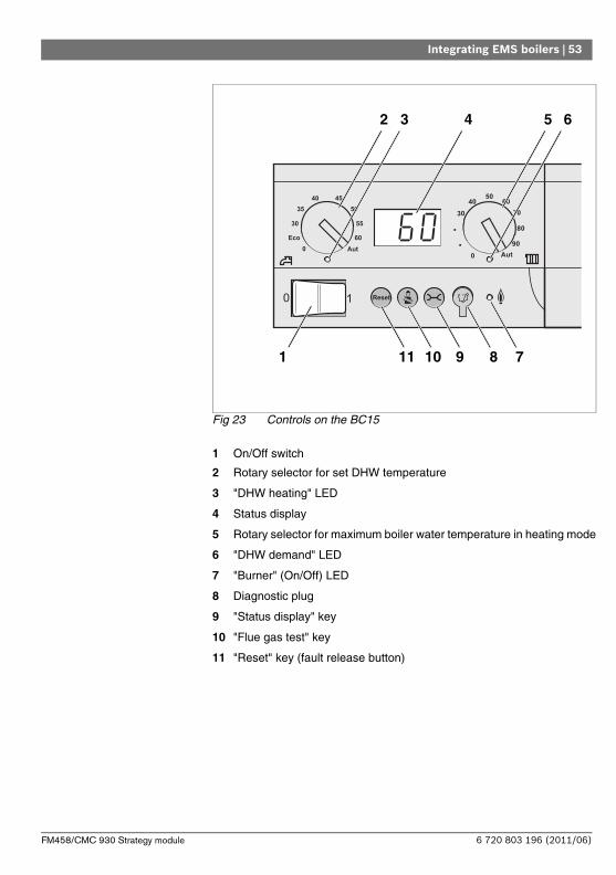
Fig 23 Controls on the BC15
1 On/Off switch
2 Rotary selector for set DHW temperature
3 "DHW heating" LED
4 Status display
5 Rotary selector for maximum boiler water temperature in heating mode
6 "DHW demand" LED
7 "Burner" (On/Off) LED
8 Diagnostic plug
9 "Status display" key
10 "Flue gas test" key
11 "Reset" key (fault release button)
42
1
5
711 910
3 6
8
6 720 803 196 (2011/06)FM458/CMC 930 Strategy module

54 | Integrating EMS boilers
Setting the output limit
The boiler output can be restricted to 11 kW (or 50 kW with higher boiler output) using a jumper on the back of the base controller.
Remove the base controller.
Remove jumper ( Fig. 24[1]) if the boiler output is to be restricted.
Jumper Status Explanation
Not insertedOutput restricted to 11 kW (50 kW) (only for boilers with UBA 3)
InsertedUnrestricted output (delivered condition)
Fig 24 Back of the BC15 base controller
1 Jumper for restricting output
1
6 720 803 196 (2011/06) FM458/CMC 930 Strategy module

Functions of the FM458/CMC 930 | 55
5 Functions of the FM458/CMC 930
In the following sections, it is explained how to use the different functions and make settings via the Programmer programming unit.
5.1 Operation with Programmer
Calling up the service level
The respective service instructions of your control unit explain exactly how to use the Programmer programming unit. Here you will get a short overview of operating the Programmer.
The Programmer has two operating levels available (level 1 with closed flap and level 2 with open flap) plus one service level (accessible via password). Various main menus are offered at the service level, giving access to sub-menus, where you can change the settings of the control units.
1 Display
2 Rotary selector
3 Function buttons
To reach the service level, press the following key combination (password), until "SERVICE LEVEL – Gen. parameters" appears on the display.
SERVICE LEVEL
GENERAL PARAM.
1
2
3
6 720 803 196 (2011/06)FM458/CMC 930 Strategy module

56 | Functions of the FM458/CMC 930
5.2 Integrating function module FM458/CMC 930 in the control unit
5.2.1 Integrate function module FM458/CMC 930 on Programmer level
After you have installed the FM458/CMC 930 function module ( see installation instructions "Modules for FB 9x0 control units"), your control unit will detect it automatically when it is switched on.
5.2.2 Integrate function module FM458/CMC 930 manually on Programmer level
Call up the service level.
Turn the rotary selector until "SERVICE LEVEL – Module selection" appears on the display.
The display shows the main menu.
Press "Display" to select the main menu "MODULE SELECTION".
The display shows "MODULE SELECTION – Slot A".
USER INFORMATION
If the function module FM458/CMC 930 is not automatically recognised, you must install it once manually via the Programmer programming unit.
SERVICE LEVEL
Module selection
MODULE SELECTION
Slot A
Boiler module
ZM 434
6 720 803 196 (2011/06) FM458/CMC 930 Strategy module

Functions of the FM458/CMC 930 | 57
Turn the rotary selector to the position (slot) where the FM458/CMC 930 function module is to be installed.
The FM458/CMC 930 function module should be installed in e.g. slot 2.
Hold down "Display" (the text in the lower line starts to flash) and turn rotary selector until the function module FM458/CMC 930 appears on the display.
Release the display key".
Press "Back".
The function module FM458/CMC 930 ("strategy module") is installed on slot 2.
Press "Back" three times or close the operating flap to reach operating level 1.
MODULE SELECTION
slot 2
Strategy module
FM458
6 720 803 196 (2011/06)FM458/CMC 930 Strategy module

58 | General specification data
6 General specification data
6.1 0 – 10 V input
As soon as a module with 0 – 10 V input has been fitted in the control unit, the following masks appear as listed in the table below:
Call up the service level. "GENERAL PARAM." appears as the first main menu.
Press "Display" to call up a submenu (here: "Min. outdoor temperature").
The display shows the selected submenu.
Turn the rotary selector until the submenu "0 – 10 V input" appears.
Module NameTemperature-based control
Output-based control
FM448/CMB 900-0-10V
Fault message module
X
FM456/CMC 910
KSE 2 (EMS) XX (CM431 V6.xx
or higher)
FM457/CMC 920
KSE 4 (EMS) XX (CM431 V6.xx
or higher)
FM458/CMC 930
Strategy module XX (CM431 V8.xx
or higher)
ZM433 Substation X
GENERAL PARAM.
Min outside temp
-10°C
6 720 803 196 (2011/06) FM458/CMC 930 Strategy module

General specification data | 59
Hold down "Display" and turn the rotary selector until the required set value appears (here: "Temp control").
The display shows the set value.
Release "Display" to save the entry.
+
GENERAL PARAM.
0-10 V input
Temp. control
Input range Factory setting
0 – 10 V inputOFF
Temp.controlOutput control
Temp. control
6 720 803 196 (2011/06)FM458/CMC 930 Strategy module

60 | General specification data
6.2 Temperature control 0 – 10 V input
If you have selected "Temp. control" for a 0 – 10 V input, you can select the start and stop point, if required, for the external 0 – 10 V input.
You can set the following:
– the set value in °C for 0 V ("Temp. control 0V equates to")
– the set value in °C for 10 V ("Temp. control 10V equates to")
The following linear curve is calculated from these values:
The start value (start point) of the curve is set to 0.6 V for a positive curve, Fig. 25 shows the factory setting.
Call up the service level. "GENERAL PARAM." appears as the first main menu.
Press "Display" to call up a submenu(here: "Min. outdoor temperature").
Fig 25 Input 0 – 10 V
x Input voltage in V (factory setting)
y Set boiler temperature in °C
6 720 803 196 (2011/06) FM458/CMC 930 Strategy module

General specification data | 61
The display shows the selected submenu.
Turn the rotary selector until submenu "Temp. control equates to 0 V" or "Temp. control equates to 10 V" appears.
Hold down "Display" and turn the rotary selector until the required set value appears (here: "5°C").
The display shows the set value.
Release "Display" to save the entry.
Press "Back" to return to the next level up.
Turn the rotary selector until submenu "Temp. control equates to 10 V" appears.
Hold down "Display" and turn the rotary selector until the required set value appears (here: "90°C").
The display shows the set value.
Release "Display" to save the entry.
GENERAL PARAM.
Min outside temp
-10°C
+
GENERAL PARAM.
Temp control
0 V equates to
5°C
+
GENERAL PARAM.
Temp control
10 V equates to
90°C
6 720 803 196 (2011/06)FM458/CMC 930 Strategy module

62 | General specification data
6.3 Output control for 0 – 10 V input
The 0 – 10 V input can also be used for output control.
If you have selected output control for the 0 – 10 V input, you can, if required, match the curve for external output control.
You can set the following:
– The set output value for 0 V ("Output control equates to 0V equates to")
– The set output value for 10 V ("Output control equates to 10V equates to")
The following linear curve is calculated from these values:
Input range Factory setting
Temperature control 0 V 5 °C – 99 °C 5 °C
Temperature control 10 V 5 °C – 99 °C 90 °C
USER INFORMATION
If a curve with a negative incline is programmed, e.g. 0 volt = 90 °C, ensure that all 0 – 10 volt inputs of a control unit are controlled. An open input corresponds to 0 V and thus to a heat demand of e.g. 90 °C.
The demand should be set parallel at all 0 – 10 V inputs of a control unit, if applicable.
6 720 803 196 (2011/06) FM458/CMC 930 Strategy module

General specification data | 63
The start value (start point) of the curve is set to 0.6 V with a positive curve.
Fig 26 0 – 10 V input
x Input voltage in V (factory setting)
y Output demand in %
USER INFORMATION
In case of external power control, the control units can no longer take internal heat demands, e.g. from heating zones or DHW function, into consideration.
USER INFORMATION
If a curve with a negative incline is programmed, e.g. 0 volt = 100 % output, ensure that all 0 – 10 volt inputs of this control unit are used. An open input corresponds to 0 V and thus to an output demand of 100 %.
The demand should be set parallel at all 0 – 10 V inputs of a control unit, if applicable.
6 720 803 196 (2011/06)FM458/CMC 930 Strategy module

64 | General specification data
Call up the service level. "GENERAL PARAM." appears as the first main menu.
Turn the rotary selector until the main menu "BOILER PARAM." appears.
Press "Display" to call up a submenu (here: "No. of boilers").
Turn the rotary selector until submenu "Output control" appears.
The display shows the selected submenu.
Hold down "Display" and turn the rotary selector until the required value appears (here: "0 V corresponds to 0%").
The selected value flashes on the display.
Release "Display" to save the entry.
Turn the rotary selector until the submenu "10 V equates to ...%" appears.
Hold down "Display" and turn the rotary selector until the required value appears (here: "10 V corresponds to 100%").
BOILER PARAM.
0-10 V input
Output-based control
+
BOILER PARAM.
Output-based control
0 V equates to
0%
+
6 720 803 196 (2011/06) FM458/CMC 930 Strategy module

General specification data | 65
The selected value flashes on the display.
Release "Display" to save the entry.
Press "Back" to return to the next level up.
BOILER PARAM.
Output-based control
10 V equates to
100%
Input range Factory setting
Output control 0 V 0 % – 100 % 0 %
Output control 10 V 0 % – 100 % 100 %
6 720 803 196 (2011/06)FM458/CMC 930 Strategy module

66 | Strategy data
7 Strategy data
7.1 Number of boilers
You select the number of boilers in this menu.
Call up the service level. "GENERAL PARAM." appears as the first main menu
Turn the rotary selector until the main menu "SERVICE LEVEL - Strategy" appears.
Press "Display" to call up a submenu (here: "Strategy data").
Turn the rotary selector until the submenu "No. of boilers" appears.
Hold down "Display" and turn the rotary selector until the required value appears (here: "1").
The selected value flashes on the display.
Release "Display" to save that value.
Press "Back" to return to the next level up.
+
Strategy data
No. of boilers
1
Setting range Factory setting
Number of boilers0 – 4 with 1 FM458/CMC 9300 – 8 with 2 FM458/CMC 930
1
6 720 803 196 (2011/06) FM458/CMC 930 Strategy module

Strategy data | 67
7.2 Maximum system temperature
You select the maximum system temperature in this menu.
Call up the service level. "GENERAL PARAM." appears as the first main menu
Turn the rotary selector until the main menu "SERVICE LEVEL - Strategy" appears.
Press "Display" to call up a submenu (here: "Strategy data").
Turn the rotary selector until the submenu "Maximum system temperature" appears.
Hold down "Display" and turn the rotary selector until the desired value appears (here: "75°C").
The selected value flashes on the display.
Release "Display" to save that value.
Press "Back" to return to the next level up.
USER INFORMATION
If you set the integration to "0", then the module assumes that the control unit should not take any heat source into consideration. All boilers are shut down. No further adjustments can be made.
+
Strategy data
Maximum system
temperature
75°C
6 720 803 196 (2011/06)FM458/CMC 930 Strategy module

68 | Strategy data
7.3 Hydraulic decoupling
In this menu you define whether a hydraulic balancing vessel is installed in the system.
Call up the service level. "GENERAL PARAM." appears as the first main menu
Turn the rotary selector until the main menu "SERVICE LEVEL - Strategy" appears.
Press "Display" to call up a submenu (here: "Strategy data").
Turn the rotary selector until the submenu "Hydraulic decoupling" appears.
Hold down "Display" and turn the rotary selector until the desired value appears (here: "yes").
The selected value flashes on the display.
Release "Display" to save that value.
Press "Back" to return to the next level up.
USER INFORMATION
Never set the maximum system temperature higher than the lowest maximum shutdown temperature of any individual boiler in the system.
Setting range Factory setting
Maximum system temperature 50 °C – 90 °C 75 °C
+
Strategy data
Hydraulic
decoupling
yes
Setting range Factory setting
Hydraulic decoupling yesno yes
6 720 803 196 (2011/06) FM458/CMC 930 Strategy module

Strategy data | 69
7.4 Boiler sequences
Fig 27 Possible boiler sequences
2 x FM458 / CMC 9301 x FM458 / CMC 930
6 720 803 196 (2011/06)FM458/CMC 930 Strategy module

70 | Strategy data
Boiler sequences are split into three categories:
The boiler sequences 1 - 24 comprise all possible boiler sequences for a 4 boiler system. In a system with 5 to 8 boilers, boilers 5 to 8 always occupy the same position at the end of the sequence. Boiler sequences 25 - 32 comprise a constant rotation of all boilers. In the boiler sequences 33 - 39, boiler 1 will always be positioned last. These sequences are intended for hydraulic systems in which boiler 1 takes over the water heating directly (hot water via EMS 3 control valve or EMS flow).
With the "Automatic" setting (factory setting), the FM458/CMC 930 determines the boiler sequence by itself, subject to the number of boilers, the selected sequence reversal and whether boiler 1 heats DHW directly.
Subject to the selected sequence reversal, up to 4 boiler sequences can be assigned (sequence A - D; every sequence is assigned a boiler sequence from Fig. 27, page 69 "Possible boiler sequences").
How is a boiler sequence adjusted?
The sequence to be adjusted (sequence A -- D) appears in the 2nd line of the Programmer display plus, if necessary, the condition to be met (e.g. "AT 15°C"); see Chapter 7.5 "Sequence switching", page 72.
On line 3 of the Programmer display, the boiler sequence appears that is listed in this sequence (the displayed number of boilers corresponds to that entered under "strategy data - no. of boilers"). "Automatic" means that the FM458/CMC 930 determines the boiler sequence (see above).
Line 4 of the Programmer display shows the number of the boiler sequence (the corresponding boiler sequence is displayed on line 3); you find an overview of the possible boiler sequences in Fig. 27, page 69 "Possible boiler sequences".
6 720 803 196 (2011/06) FM458/CMC 930 Strategy module

Strategy data | 71
Example of a boiler sequence entry:
– System with 3 boilers
– No set sequence reversal
>> Only one sequence (A) can be selected.
Call up the service level. "GENERAL PARAM." appears as the first main menu
Turn the rotary selector until the main menu "SERVICE LEVEL - Strategy" appears.
Press "Display" to call up a submenu (here: "Strategy data").
Turn the rotary selector until the submenu "LagA" appears.
The display shows the submenu.
Hold down "Display" and turn the dial until the required value appears (here: "2-3-1") of boiler sequence 5.
The selected value flashes on the display.
Release "Display" to save that value.
Press "Back" to return to the next level up.
Strategy data
LagA
Automatic
0
+
Strategy data
LagA
2-3-1
5
6 720 803 196 (2011/06)FM458/CMC 930 Strategy module

72 | Strategy data
7.5 Sequence switching
With this parameter you determine whether there should be a change between the boiler sequences.
Setting options:
– noneThe same sequence will be used (no change).
– Hours runThe sequences are changed subject to hours run by the lead boiler.
– Outside temperatureThe sequences are changed subject to the outside temperature.
– DailySequences are changed daily (at 00:00 h).
– External contactThe system changes between two sequences subject to the switching state (open/closed) of the "ZW" contact.
Call up the service level. "GENERAL PARAM." appears as the first main menu
Turn the rotary selector until the main menu "SERVICE LEVEL - Strategy" appears.
Press "Display" to call up the submenu (here: "Strategy data").
Turn the rotary selector until the submenu "Sequence revers.".
USER INFORMATION
A heat meter can no longer be connected if the sequence reversal is activated via the external contact.
6 720 803 196 (2011/06) FM458/CMC 930 Strategy module

Strategy data | 73
Hold down "Display" and turn the rotary selector until the desired value appears (here: "none").
The selected value flashes on the display.
Release "Display" to save that value.
Press "Back" to return to the next level up.
7.5.1 "Sequence revers. none"
Only sequence A can be selected if "Sequence revers. none" has been selected.
Selection of sequence A
Hold down "Display" and turn the rotary selector until the required value appears (here: "0").
The selected value flashes on the display.
Release "Display" to save that value.
+
Strategy data
Sequence switching
none
Setting range Factory setting
Sequence switching
noneWorking hours
Outside temperaturedaily
external contact
none
USER INFORMATION
After selecting the sequence reversal, additional parameters can be selected by turning the rotary selector clockwise.
+
Strategy data
LagA
Automatic
0
6 720 803 196 (2011/06)FM458/CMC 930 Strategy module

74 | Strategy data
Press "Back" to return to the next level up.
7.5.2 Sequence reversal subject to hours run
When "Sequence revers. hours run" has been selected, turning the rotary selector clockwise will display the menu for the hours after which the sequence should be reversed. The boiler sequence is changed over when the lead boiler reaches the number of hours selected here.
Hold down "Display" and turn the rotary selector until the required value appears (here: "250 hours").
The selected value flashes on the display.
Release "Display" to save that value.
Press "Back" to return to the next level up.
Setting range Factory setting
Sequence A 0 – 39 0 (= Automatic)
USER INFORMATION
The following boiler sequence is implemented when "Automatic" is selected:
Sequence no. 25 or sequence no. 33
+
Strategy data
Lead-Lag acc. to
250 hours
Setting range Factory setting
Hours sequence revers. 10 h – 1000 h 250 h
USER INFORMATION
After turning the rotary selector clockwise, the sequences A - D can be selected.
6 720 803 196 (2011/06) FM458/CMC 930 Strategy module

Strategy data | 75
Setting the boiler sequences for sequences A - D
Hold down "Display" and turn the rotary selector until the required value appears (here: "0").
The selected value flashes on the display.
Release "Display" to save that value.
Press "Back" to return to the next level up.
+
Strategy data
LagA
Automatic
0
Setting range Factory setting
Sequence A 0 – 39 0 (= Automatic)
Sequence B 0 – 39 0 (= Automatic)
Sequence C 0 – 39 0 (= Automatic)
Sequence D 0 – 39 0 (= Automatic)
USER INFORMATION
The "Automatic" setting will only be accepted if "Automatic" was selected for all sequences (A - D).The "Automatic" setting will be ignored, if for at least one sequence "Automatic" was not selected, and the change will only include the factory-set boiler sequences.
With the "Automatic" setting, the following boiler sequences are implemented for all sequences:
Two-boiler system: No. 25 and 26 or no. 33 (cycle reversal not possible)
Three-boiler system: No. 25 to 27 or no. 33 and 34
Four-boiler system: No. 25 to 28 or no. 33 to 35
Five-boiler system: No. 25 to 29 or no. 33 to 36
Six-boiler system: No. 25 to 30 or no. 33 to 37
Seven-boiler system: No. 25 to 31 or no. 33 to 38
Eight-boiler system: No. 25 to 32 or no. 33 to 39
6 720 803 196 (2011/06)FM458/CMC 930 Strategy module

76 | Strategy data
7.5.3 Sequence reversal subject to outside temperature
If "Sequence revers. outside temperature" has been selected, turning the rotary selector clockwise will display the menus for changeover thresholds for sequences A – C. The changeover threshold for sequence D cannot be adjusted; it is the result of the changeover threshold for C and applies to all temperatures set lower than in sequence C.
Hold down "Display" and turn the rotary selector until the desired value appears (here: "15°C").
The selected value flashes on the display.
Release "Display" to save that value.
The additional sequences B - C are selected by simply turning the rotary selector (no need to push "Display").
Press "Back" to return to the next level up.
+
Strategy data
LagA
OT >
15°C
Setting range Factory setting
Changeover thresholdSequence A
–20 °C to 30 °C 15 °C
Changeover thresholdSequence B
–29 °C to changeover threshold sequence A – 1 K
10 °C
Changeover thresholdSequence C
–29 °C to changeover threshold sequence B – 1 K
5 °C
Changeover thresholdSequence D
not adjustable none
USER INFORMATION
If –30 °C is selected when setting the changeover threshold for sequence B, then the temperature display will be hidden; sequences C and D will no longer be adjustable and will not be implemented.
If –30 °C is selected when setting the changeover threshold for sequence C, then the temperature display will be hidden; sequences D will no longer be adjustable and will not be implemented.
6 720 803 196 (2011/06) FM458/CMC 930 Strategy module

Strategy data | 77
Determining the sequences for outside temperature thresholds for sequences A – D
Once the outside temperature thresholds have been set, turning the rotary selector further clockwise will display the menus for setting the boiler sequences for sequences A – D.
Hold down "Display" and turn the rotary selector until the required value appears (here: "0").
The selected value flashes on the display.
Release "Display" to save that value.
Press "Back" to return to the next level up.
+
Strategy data
LagA OT > 15
Automatic
0
Setting range Factory setting
Sequence A 0 – 39 0 (= Automatic)
Sequence B 0 – 39 0 (= Automatic)
Sequence C 0 – 39 0 (= Automatic)
Sequence D 0 – 39 0 (= Automatic)
USER INFORMATION
For the sequences implemented in "Automatic", see Page 20.
6 720 803 196 (2011/06)FM458/CMC 930 Strategy module

78 | Strategy data
7.5.4 "Sequence revers daily"
If "Sequence revers daily" was selected, turning the rotary selector further clockwise will display the menus for the boiler sequences of sequences A - D.
Hold down "Display" and turn the rotary selector until the required value appears (here: "0").
The selected value flashes on the display.
Release "Display" to save that value.
Press "Back" to return to the next level up.
+
Strategy data
LagA
Automatic
0
Setting range Factory settingSequence A 0 – 39 0 (= Automatic)Sequence B 0 – 39 0 (= Automatic)Sequence C 0 – 39 0 (= Automatic)Sequence D 0 – 39 0 (= Automatic)
USER INFORMATION
The "Automatic" setting will only be accepted if "Automatic" was selected for all sequences (A - D).The "Automatic" setting will be ignored, if for at least one sequence "Automatic" was not selected, and the change will only include the factory-set boiler sequences.With the "Automatic" setting, the following boiler sequences are implemented for all sequences:Two-boiler system: No. 25 and 26 or no. 33 (sequence reversal not possible)Three-boiler system: No. 25 to 27 or no. 33 and 34
Four-boiler system: No. 25 to 28 or no. 33 to 35
Five-boiler system: No. 25 to 29 or no. 33 to 36
Six-boiler system: No. 25 to 30 or no. 33 to 37
Seven-boiler system: No. 25 to 31 or no. 33 to 38
Eight-boiler system: No. 25 to 32 or no. 33 to 39
6 720 803 196 (2011/06) FM458/CMC 930 Strategy module

Strategy data | 79
7.5.5 "Sequence reverse external contact"
If "Sequence reverse external contact" has been selected, turning the rotary selector twice clockwise will display the menus for sequence A (ZW open) and B (ZW closed).
Hold down "Display" and turn the rotary selector until the required value appears (here: "0").
The selected value flashes on the display.
Release "Display" to save that value.
Press "Back" to return to the next level up.
+
Strategy data
Sequence A ZW open
Automatic
0
Setting range Factory setting
Sequence A ZW open 0 – 39 0 (= Automatic)
Sequence B ZW closed 0 – 39 0 (= Automatic)
USER INFORMATION
Boiler sequence 25 or 33 will be operated if, for sequence A, "ZW open automatic" was selected. Boiler sequence 26 or 34 will be operated if, for sequence B, "ZW closed automatic" was selected.
6 720 803 196 (2011/06)FM458/CMC 930 Strategy module

80 | Strategy data
7.6 Load limit
With this parameter you determine whether there should be a load limit.
Setting options:
– noneStrategy can always enable all boilers.
– Outside temperatureA different number of boilers can be enabled, subject to the outside temperature.
– External contactOnly a specific number of boilers can be enabled subject to the switching state (open/closed) of the "EL" contact.
Call up the service level. "GENERAL PARAM." appears as the first main menu
Turn the rotary selector until the main menu "SERVICE LEVEL - Strategy" appears.
Press "Display" to call up a submenu (here: "Strategy data").
Turn the rotary selector until submenu "Load limit" appears.
Hold down "Display" and turn the rotary selector until the desired value appears (here: "none").
The selected value flashes on the display.
Release "Display" to save that value.
Press "Back" to return to the next level up.
+
Strategy data
Load limit
none
6 720 803 196 (2011/06) FM458/CMC 930 Strategy module

Strategy data | 81
7.6.1 Load limit according to outside temperature
If "Load limit acc. to outside temperature" was selected, turning the rotary selector clockwise will display the menu for entering load limit temperature threshold 1.
Hold down "Display" and turn the rotary selector until the desired value appears (here: "17°C").
The selected value flashes on the display.
Release "Display" to save that value.
Press "Back" to return to the next level up.
Setting range Factory setting
Load limitnone
Outside temperatureexternal contact
none
+
Strategy data
Limited to
1 boiler OT>
17°C
Setting range Factory setting
Temperature threshold –31 °C to 30 °C 17 °C
USER INFORMATION
It is possible to set the number of boiler (see Page 83).
6 720 803 196 (2011/06)FM458/CMC 930 Strategy module

82 | Strategy data
Enabling all boilers
Turning the rotary selector further clockwise will display the menu for entering load limit temperature threshold 2.
Hold down "Display" and turn the rotary selector until the desired value appears (here: "10°C").
The selected value flashes on the display.
Release "Display" to save that value.
Press "Back" to return to the next level up.
+
Strategy data
No limit
OT<
10°C
Setting range Factory setting
Temperature threshold–31 °C up to temperature
threshold 110 °C
6 720 803 196 (2011/06) FM458/CMC 930 Strategy module

Strategy data | 83
Number of boilers at outside temperatures above threshold 1
Turning the rotary selector further clockwise will enable you to select how many boilers can be enabled above temperature threshold 1.
Hold down "Display" and turn the rotary selector until the required value appears (here: "1").
The selected value flashes on the display.
Release "Display" to save that value.
Press "Back" to return to the next level up.
+
Strategy data
OT> 17°C
enabled Boiler
1
Setting range Factory setting
Number of boilers0 to no. of boilers – 1
1
6 720 803 196 (2011/06)FM458/CMC 930 Strategy module

84 | Strategy data
7.6.2 Load limit via external contact
If "Load limit acc. to external contact" was selected, turning the rotary selector clockwise will display the menu for entering the boilers to be enabled when the external contact is closed.
Hold down "Display" and turn the rotary selector until the required value appears (here: "1").
The selected value flashes on the display.
Release "Display" to save that value.
Press "Back" to return to the next level up.
+
Strategy data
With contact closed
enabled Boiler
1
Setting range Factory setting
Number of boilers0 to no. of boilers – 1
1
USER NOTE
All boilers will be enabled with the contact open.
6 720 803 196 (2011/06) FM458/CMC 930 Strategy module

Strategy data | 85
7.6.3 Operating mode serial / parallel
In this menu you can determine whether the boilers are to be enabled in series or in parallel.
For a definition of the serial or parallel operating mode, see Chapter 2.3.4 "Series operation", page 16 or Chapter 2.3.5 "Parallel operation", page 17.
Call up the service level. "GENERAL PARAM." appears as the first main menu
Turn the rotary selector until the main menu "SERVICE LEVEL - Strategy" appears.
Press "Display" to call up a submenu (here: "Strategy data").
Turn the rotary selector until submenu "Operating mode" appears.
Hold down "Display" and turn the rotary selector until the desired value appears (here: "serial").
The selected value flashes on the display.
Release "Display" to save that value.
Press "Back" to return to the next level up.
+
Strategy data
Operating mode
serial
Setting range Factory setting
Operating modeserial
parallelserial
6 720 803 196 (2011/06)FM458/CMC 930 Strategy module

86 | Strategy data
7.6.4 Lead boiler run-on time (pump/servomotor)
This menu enables you to set the run-on time for the pump or servomotor of the lead boiler.
Call up the service level. "GENERAL PARAM." appears as the first main menu
Turn the rotary selector until the main menu "SERVICE LEVEL - Strategy" appears.
Press "Display" to call up a submenu (here: "Strategy data").
Turn the rotary selector until the submenu "Lead boiler" appears.
Hold down "Display" and turn the rotary selector until the required value appears (here: "60 min").
The selected value flashes on the display.
Release "Display" to save that value.
Press "Back" to return to the next level up.
+
Strategy data
Lead boiler
After-run time
60 min
Setting range Factory setting
After-run time0 min – 60 min
Constant operation60 min.
6 720 803 196 (2011/06) FM458/CMC 930 Strategy module

Strategy data | 87
7.6.5 Lag boiler run-on time (pump/servomotor)
This menu enables you to set the run-on time for the pump or servomotor of the lag boiler.
Call up the service level. "GENERAL PARAM." appears as the first main menu
Turn the rotary selector until the main menu "SERVICE LEVEL - Strategy" appears.
Press "Display" to call up a submenu (here: "Strategy data").
Turn the rotary selector until the submenu "Lag boiler" appears.
Hold down "Display" and turn the rotary selector until the required value appears (here: "5 min").
The selected value flashes on the display.
Release "Display" to save that value.
Press "Back" to return to the next level up.
+
Strategy data
Lag boiler
After-run time
5 min
Setting range Factory setting
After-run time0 min – 60 min
Constant operation5 min.
USER INFORMATION
Select the run-on time of the lag boiler so that you can be sure that the boiler flow temperature has reached the same level as that of the return.
The pump run-on time selected for the EMS boiler must not exceed the run-on time selected in this menu.
6 720 803 196 (2011/06)FM458/CMC 930 Strategy module

88 | DHW data
8 DHW data
The FM458/CMC 930 strategy module supports DHW heating via the EMS boiler 1 (only in control unit CSM 920). DHW heating is achieved with the help of a primary pump or a changeover valve.
8.1 Selecting the DHW cylinder
Here, you can log the DHW cylinder on and off. If a cascade module is installed, you can select the type of water connections for the DHW cylinder.
Call up the service level. "GENERAL PARAM." appears as the first main menu
Turn the rotary selector until the main menu "SERVICE LEVEL - DHW" appears.
The display shows the main menu.
Press "Display" to call up a submenu (here: "DHW").
The automatically recognised DHW cylinder will be preset on the display.
USER INFORMATION
If a DHW module (e.g. FM441/CMM 910) is installed in a control unit CFB 930, DHW will be heated exclusively via the module.In this case, the DHW settings described in this chapter will not apply. For applicable settings see the documentation of the corresponding module/control unit.
SERVICE LEVEL
Domestic hot water
DHW DATA
Domestic hot water
EMS-3-way valve
6 720 803 196 (2011/06) FM458/CMC 930 Strategy module

DHW data | 89
Hold down "Display" and turn the rotary selector until the desired value appears (here: "No").
The display shows the set value.
Release "Display" to save that value.
Press "Back" to return to the next level up.
DHW DATA
Domestic hot water
no
Setting range Factory setting
Domestic hot water
noEMS-3-way valve
EMS primary pumpEMS integral water heater
automatically recognised presets in online mode
Parameter EMS-3-way valve EMS primary pumpEMS integral water
heater
Setting the temperature range X X X
Selecting switching optimisation X X
Selecting residual heat use X X
Setting hysteresis X X
Thermal disinfection* X X
Daily heating* X X X
DHW circulation pump* X X X
Tab. 5 Possible parameters, subject to hydraulic connection
* with subsequent settings
USER INFORMATION
The selection EMS tank primary pump is only possible in 1-boiler systems.
6 720 803 196 (2011/06)FM458/CMC 930 Strategy module

90 | DHW data
USER INFORMATION
When connecting a wall mounted boiler with stratification technology, observe the following:
– Parameter setting:
–Type of DHW heating: "EMS 3-way valve"
–Therm. disinfect: "No"
–DHW circulation pump: "No"
–Maximum adjustable DHW temperature (range): 60 °C.
– No solar DHW heating
– The DHW hysteresis is permanently set inside the boiler. This setting has priority over any change made in the menu.
– DHW comfort function: In night mode, the boiler can start when DHW is drawn (subject to the actual DHW temperature and the amount of DHW drawn).
– Display of the throughput (via flow meter) via BC15.
USER INFORMATION
The selection EMS tank primary pump is only possible in 1-boiler systems.
USER INFORMATION
The selection EMS tank primary pump is only possible in 1-boiler systems.
6 720 803 196 (2011/06) FM458/CMC 930 Strategy module

DHW data | 91
8.2 Setting the temperature range
With this function you can set the upper limit for the required DHW temperature.
Call up the service level. "GENERAL PARAM." appears as the first main menu
Turn the rotary selector until the main menu "SERVICE LEVEL - DHW" appears.
Press "Display" to call up a submenu (here: "DHW").
The display shows submenu "DHW".
Turn the rotary selector until the submenu "Range to" appears.
. The display shows the submenu "Range to".
Hold down "Display" and turn the rotary selector until the desired value appears (here: "80 °C").
WARNING!
RISK OF SCALDING
from hot water.There is a risk of scalding if the required DHW temperature is set higher than 60°C.
Do not draw off DHW unmixed.
DHW DATA
Domestic hot water
EMS-3-way valve
DHW DATA
Range to
60 °C
6 720 803 196 (2011/06)FM458/CMC 930 Strategy module

92 | DHW data
The display shows the set value.
Release "Display" to save that value.
Press "Back" to return to the next level up.
8.3 Selecting switching optimisation
If you select the "Optimisation" function, DHW heating will begin prior to the actual start point. The control unit calculates the timing of the start, taking into consideration the residual cylinder heat and the commencement of the heating for the heating circuits, so that the DHW temperature is reached in good time.
Call up the service level. "GENERAL PARAM." appears as the first main menu
Turn the rotary selector until the main menu "SERVICE LEVEL - DHW" appears.
Press "Display" to call up a submenu (here: "DHW").
The display shows submenu "DHW".
Turn the rotary selector until the submenu "Optimisation for starting" appears.
DHW DATA
Range to
80 °C
Setting range Factory setting
Range to 60 °C - 80 °C 60°C
DHW DATA
Domestic hot water
EMS-3-way valve
6 720 803 196 (2011/06) FM458/CMC 930 Strategy module

DHW data | 93
. The display shows the submenu "Start optimisation".
Hold down "Display" and turn the rotary selector until the desired value appears (here: "yes").
The display shows the set value.
Release "Display" to save that value.
Press "Back" to return to the next level up.
8.4 Selecting residual heat use
If you select the "Resid. heat use" function, you can utilise the residual boiler heat for cylinder heating.
"Residual heat use yes"
If you select "Resid. heat use yes", the control unit calculates the shutdown temperature of the burner and the runtime of the primary pump via the residual boiler heat, until the cylinder is fully heated. The burner is switched OFF before the set DHW temperature is reached. The cylinder primary pump continues to operate. The control unit calculates the runtime of the primary pump (between 3 and 30 minutes) to heat the cylinder.
DHW DATA
Optimisation
for starting
no
DHW DATA
Optimisation
for starting
Yes
Setting range Factory setting
Optimisationyesno
no
6 720 803 196 (2011/06)FM458/CMC 930 Strategy module

94 | DHW data
"Residual heat use no"
If you select "Resid. heat use no" you will only utilise a little residual heat. The burner runs until the required DHW temperature has been reached. The cylinder primary pump runs on for 3 minutes after the burner has been switched off.
Call up the service level. "GENERAL PARAM." appears as the first main menu
Turn the rotary selector until the main menu "SERVICE LEVEL - DHW" appears.
Press "Display" to call up a submenu (here: "DHW").
The display shows submenu "DHW".
Turn the rotary selector until the submenu "Resid. heat use" appears.
. The display shows the submenu "Resid. heat use".
Hold down "Display" and turn the rotary selector until the required value appears (here: "No").
The display shows the set value.
Release "Display" to save that value.
DHW DATA
Domestic hot water
EMS-3-way valve
DHW DATA
Residual heat utilisation
yes
DHW DATA
Residual heat utilisation
no
6 720 803 196 (2011/06) FM458/CMC 930 Strategy module

DHW data | 95
Press "Back" to return to the next level up.
8.5 Setting hysteresis
With the "Hysteresis" function, you can determine at how many Kelvin (K) below the set DHW temperature the reheating of the cylinder begins.
Call up the service level. "GENERAL PARAM." appears as the first main menu
Turn the rotary selector until the main menu "Service level - DHW" appears.
Press "Display" to call up a submenu (here: "DHW").
The display shows submenu "DHW".
Turn the rotary selector until the submenu "Hysteresis" appears.
. The display shows the submenu "Hysteresis".
Hold down "Display" and turn the rotary selector until the required value appears (here: "-20 K").
Setting range Factory setting
Residual heat utilisationyesno
yes
DHW DATA
Domestic hot water
EMS-3-way valve
DHW DATA
Hysteresis
-5K
6 720 803 196 (2011/06)FM458/CMC 930 Strategy module

96 | DHW data
The display shows the set value.
Release "Display" to save that value.
Press "Back" to return to the next level up.
DHW DATA
Hysteresis
-20K
Setting range Factory setting
Hysteresis –20 K – 2 K –5 K
6 720 803 196 (2011/06) FM458/CMC 930 Strategy module

DHW data | 97
8.6 Selecting and setting up thermal disinfection
If you select the "Therm. disinfect" function, the DHW is brought to a temperature (70 °C) once or several times a week which is high enough to kill off germs (e.g. Legionnella bacteria).
The cylinder primary pump and DHW circulation pump run constantly during the thermal disinfection process.
If you have selected "Therm. disinfect yes", thermal disinfection commences according to factory settings or your own preferences.
You can adjust the factory settings for thermal disinfection via additional menus.
The system tries to reach the set thermal disinfection temperature for three hours. If that fails, the fault message "Therm. disinfect failed" appears.
You may also set up thermal disinfection via your own switching program.
Call up the service level. "GENERAL PARAM." appears as the first main menu
Turn the rotary selector until the main menu "SERVICE LEVEL - DHW" appears.
Press "Display" to call up a submenu (here: "DHW").
The display shows submenu "DHW".
Turn the rotary selector until the submenu "Therm. disinfect" appears.
DHW DATA
Domestic hot water
EMS-3-way valve
6 720 803 196 (2011/06)FM458/CMC 930 Strategy module

98 | DHW data
. The display shows the submenu "Therm. disinfect".
Hold down "Display" and turn the rotary selector until the desired value appears (here: "yes").
The display shows the set value.
Release "Display" to save that value.
Press "Back" to return to the next level up.
DHW DATA
Thermal
disinfect
no
DHW DATA
Thermal
disinfect
Yes
Setting range Factory setting
Thermal disinfectionnoyes
no
6 720 803 196 (2011/06) FM458/CMC 930 Strategy module

DHW data | 99
8.7 Setting the thermal disinfection temperature
You can set the thermal disinfection temperature via the "Therm. disinfect temperature" function.
Call up the service level. "GENERAL PARAM." appears as the first main menu
Turn the rotary selector until the main menu "SERVICE LEVEL - DHW" appears.
Press "Display" to call up a submenu (here: "DHW").
The display shows submenu "DHW".
Turn the rotary selector until the submenu "Therm. disinfect temperature" appears.
. The display shows the submenu "Therm. disinfect temperature".
Hold down "Display" and turn the rotary selector until the required value appears (here: "75 °C").
WARNING!
RISK OF SCALDING
from hot water.
If the DHW circuit is not equipped with a thermostatic mixer, never open the hot water taps/valves on their own (i.e. without mixing in cold water) during or immediately after thermal disinfection.
DHW DATA
Domestic hot water
EMS-3-way valve
DHW DATA
Temperature
Therm. disinfect
70°
6 720 803 196 (2011/06)FM458/CMC 930 Strategy module

100 | DHW data
The display shows the set value.
Release "Display" to save that value.
Press "Back" to return to the next level up.
8.8 Setting the day of the week for thermal disinfection
You can set the day of the week when thermal disinfection should be carried out via the "Weekday Therm. disinfect" function.
Call up the service level. "GENERAL PARAM." appears as the first main menu
Turn the rotary selector until the main menu "SERVICE LEVEL - DHW" appears.
Press "Display" to call up a submenu (here: "DHW").
The display shows submenu "DHW".
Turn the rotary selector until the submenu "Therm. disinfect weekday" appears.
. The display shows the submenu "Therm. disinfect weekday".
DHW DATA
Temperature
Therm. disinfect
75 °C
Setting range Factory setting
Therm. disinfect temperature 65 °C – 75 °C 70°C
DHW DATA
Domestic hot water
EMS-3-way valve
DHW DATA
Weekday
Therm. disinfect
Tuesday
6 720 803 196 (2011/06) FM458/CMC 930 Strategy module

DHW data | 101
Hold down "Display" and turn the rotary selector until the required value appears (here: "Sunday").
The display shows the set value.
Release "Display" to save that value.
Press "Back" to return to the next level up.
8.9 Setting the time for thermal disinfection
You can set the time of day when thermal disinfection should be carried out via the "Therm. disinfect time" function.
Call up the service level. "GENERAL PARAM." appears as the first main menu
Turn the rotary selector until the main menu "SERVICE LEVEL - DHW" appears.
Press "Display" to call up a submenu (here: "DHW").
The display shows submenu "DHW".
Turn the rotary selector until the submenu "Therm. disinfect time" appears.
DHW DATA
Weekday
Therm. disinfect
Sunday
Setting range Factory setting
Weekday Therm. disinfectMonday – Sunday
daily Tuesday
DHW DATA
Domestic hot water
EMS-3-way valve
6 720 803 196 (2011/06)FM458/CMC 930 Strategy module

102 | DHW data
. The display shows the submenu "Therm. disinfect time".
Hold down "Display" and turn the rotary selector until the required value appears (here: "18:00").
The display shows the set value.
Release "Display" to save that value.
Press "Back" to return to the next level up.
DHW DATA
Clock time
Therm. disinfect
1:00
DHW DATA
Clock time
Therm. disinfect
18:00
Setting range Factory setting
Time of disinfection 0:00 – 23:00 1:00
6 720 803 196 (2011/06) FM458/CMC 930 Strategy module

DHW data | 103
8.10 Daily heat-up
When daily heat-up is set, the DHW (which may include a solar storage tank, if installed) is heated to 60 °C once a day to prevent legionella bacteria from multiplying in the DHW. This complies with the requirements of DVGW Code of Practice W551.
The time when the cylinder is heated can be adjusted.
Call up the service level. "GENERAL PARAM." appears as the first main menu
Turn the rotary selector until the main menu "SERVICE LEVEL - DHW" appears.
Press "Display" to call up a submenu (here: "DHW").
The display shows submenu "DHW".
Turn the rotary selector until the submenu "Daily heat-up" appears.
. The display shows the submenu "Daily heat-up".
Hold down "Display" and turn the rotary selector until the required value appears (here: "18:00").
DHW DATA
Domestic hot water
EMS-3-way valve
DHW DATA
Daily
Heat-up
Inactive
6 720 803 196 (2011/06)FM458/CMC 930 Strategy module

104 | DHW data
The display shows the set value.
Release "Display" to save that value.
Press "Back" to return to the next level up.
8.11 Selecting the DHW circulation pump
You can set DHW to be immediately available at the draw-off points via the "DHW circulation" function.
Call up the service level. "GENERAL PARAM." appears as the first main menu
Turn the rotary selector until the main menu "SERVICE LEVEL - DHW" appears.
Press "Display" to call up a submenu (here: "DHW").
The display shows submenu "DHW".
DHW DATA
Daily
Heat-up
18:00
USER INFORMATION
If the DHW was heated to 60 °C within the last 12 hours, it is not heated at the specified time.
Setting range Factory setting
Time of disinfectionInactive
0:00 – 23:00Inactive
DHW DATA
Domestic hot water
EMS-3-way valve
6 720 803 196 (2011/06) FM458/CMC 930 Strategy module

DHW data | 105
Turn the rotary selector until the submenu "DHW circulat" appears.
. The display shows the submenu "DHW circulation".
Hold down "Display" and turn the rotary selector until the required value appears (here: "No").
The display shows the set value.
Release "Display" to save that value.
Press "Back" to return to the next level up.
DHW DATA
DHW circulat.
Yes
DHW DATA
DHW circulat.
no
Setting range Factory setting
DHW circulat.yesno
yes
6 720 803 196 (2011/06)FM458/CMC 930 Strategy module

106 | DHW data
8.12 Setting the DHW circulation pump intervals
You can reduce operating costs using the intermittent DHW circulation pump mode.
You can determine that DHW is immediately available at the draw-off points via the "DHW circulat per hour" function.
The set interval applies during the period when the time program enables the DHW circulation pump. This may be:
– The factory-set DHW circulation pump program
– Your own DHW circulation pump program
– A connection to the heating circuit switching times
In constant mode the DHW circulation pump operates continuously when in day mode, and is switched off in night mode.
Example:
Your own time program was created to start the DHW circulation pump between05:30 – 22:00 with setting "DHW circulation per hour 2 times ON".
The DHW circulation pump is switched on in cycles
– at 05:30 h for 3 minutes
– at 06:00 h for 3 minutes
– at 06:30 h for 3 minutes
– etc. until 22:00 h.
Call up the service level. "GENERAL PARAM." appears as the first main menu
Turn the rotary selector until the main menu "SERVICE LEVEL - DHW" appears.
Press "Display" to call up a submenu (here: "DHW").
6 720 803 196 (2011/06) FM458/CMC 930 Strategy module

DHW data | 107
The display shows submenu "DHW".
Turn the rotary selector until the submenu "DHW circulat per hour" appears.
. The display shows the submenu "DHW circulation per hour".
Hold down "Display" and turn the rotary selector until the required value appears (here: "off"). The DHW circulation pump will now only operate during heating once.
The display shows the set value.
Release "Display" to save that value.
Press "Back" to return to the next level up.
DHW DATA
Domestic hot water
EMS-3-way valve
DHW DATA
DHW circulat.
per hour
2 times on
DHW DATA
DHW circulat.
per hour
Off
Setting range Factory setting
DHW circulation per hour
Off1 times on2 times on3 times on4 times on5 times on6 times on
Constant operation
2 times on
6 720 803 196 (2011/06)FM458/CMC 930 Strategy module

108 | Recording heat consumption
9 Recording heat consumption
In its basic version, the control unit software enables you to calculate the heat demand of a heating system via the setting of the burner output (for further information see the service instructions of the relevant control unit).
9.1 Setting the recording of heat demand "acc. to impulses"
Display the heat demand via the input provided on the Programmer programming unit, if a heat meter (WMZ) is integrated into the heating system. The FM458/CMC 930 function module has a pulse counter input, which must be enabled with the Programmer programming unit.
Call up the service level. "GENERAL PARAM." appears as the first main menu
Press "Display" to call up a submenu (here: "Min. outside temp").
The display shows the submenu "Min. outside temp".
Turn the rotary selector until the submenu "Heat amount - no display" appears.
USER INFORMATION
If the FM458/CMC 930 module has been installed and the heat volume is recorded via the heat meter (WMZ), you cannot calculate the heat demand via the burner setting, as one function cancels out the other. This display will not be shown on the Programmer programming unit. Selecting one choice disables the alternative function.
GENERAL PARAM.
Min outside temp
-10 °C
6 720 803 196 (2011/06) FM458/CMC 930 Strategy module

Recording heat consumption | 109
. The display shows the submenu "Heat amount - no display".
Hold down "Display" and turn the rotary selector until the desired value appears (here: "acc. to impulses").
The display shows the set value.
Release "Display" to save that value.
Press "Back" to return to the next level up.
* This option only appears if the relevant module was installed and the corresponding function was selected.
GENERAL PARAM.
Amount of heat
no display
GENERAL PARAM.
Amount of heat
acc. to impulses
Setting range Factory setting
Amount of heat
no displayacc. to impulsesacc. to burner*
Solar*
no display
6 720 803 196 (2011/06)FM458/CMC 930 Strategy module

110 | Recording heat consumption
9.2 Matching the impulse value
Now match the impulse value of the heat meter to the optional settings of the Programmer programming unit.
Turn the rotary selector until the submenu "Impulse value" appears.
. The display shows the submenu "impulse value".
Hold down "Display" and turn the rotary selector until the desired value appears (here: "10 kW/Im").
The display shows the set value.
Release "Display" to save that value.
Press "Back" to return to the next level up.
GENERAL PARAM.
Impulse value
1 kW/Im
GENERAL PARAM.
Impulse value
10 kW/Im
USER INFORMATION
The impulse setting of your control unit must absolutely match the impulse setting of the heat meter.Where that is not the case, errors will occur during counting.
Setting range Factory setting
Impulse value
1 kW/pulse10 kW/pulse
100 kW/pulse1000 kW/pulse
1 kW/pulse
6 720 803 196 (2011/06) FM458/CMC 930 Strategy module

Recording heat consumption | 111
9.3 Scanning heat demand
Open the Programmer programming unit flap.
Turn the rotary selector until the display shows the various heat consumption values.
You can scan the daily, weekly or annual consumption.
Tab. 6 Possible heat consumption displays
Daily consumpt.
Current
500 kWh
Weekly consumpt.
Current
2430 kWh
Annual consumpt.
Current
354 MWh
Display of heat consumption dataDaily consumpt. Weekly consumpt. Annual consumpt.
Current Current CurrentYesterday one week ago one year ago
Day before yest. two weeks ago two years agoMetering period
from 00:00to 00:00
from Mondayto Sunday
from 01.01.XXto 31.12.XX
USER INFORMATION
Changes to the date and time falsify the correct display of consumption values and may result in loss of data.
USER INFORMATION
The heat consumption of the heating system is shown in kWh and above 10.000 kWh in MWh.
6 720 803 196 (2011/06)FM458/CMC 930 Strategy module

112 | Recording heat consumption
9.4 Restarting the heat consumption count
First carry out a reset before starting a new heat consumption count.
Call up the service level. "GENERAL PARAM." appears as the first main menu
Turn the rotary selector until the main menu "SERVICE LEVEL - Reset" appears.
The display shows the main menu.
Press "Display" to select the main menu "RESET".
Turn the rotary selector until the submenu "Heat amount" appears.
The display shows the submenu "Heat amount".
Hold down "Display" until "SERVICE LEVEL – Reset" appears on the display.
The blocks in the last line disappear one after the other. The settings are reset when no further blocks are displayed. The reset operation will be terminated if you release the key before all blocks have disappeared. After implementing a reset, the display will revert to the next higher level.
Now the heat volume will be counted from zero.
Press "Back" to return to the next level up.
SERVICE LEVEL
Reset
RESET
Amount of heat
6 720 803 196 (2011/06) FM458/CMC 930 Strategy module

Relay test | 113
10 Relay test
Call up the service level. "GENERAL PARAM." appears as the first main menu
Turn the rotary selector until main menu "Relay test" appears.
The display shows the main menu "SERVICE LEVEL - relay test".
Press "Display" to select the main menu "RELAY TEST".
The display shows the submenu "Boiler".
Turn the rotary selector until the submenu "Relay test - strategy FM458" appears.
Press "Display" to select the submenu "Relay test - strategy FM458".
The display shows the selected submenu.
Hold down "Display" and turn the rotary selector until the required value appears (here: "Current fault").
SERVICE LEVEL
Relay test
RELAY TEST
Boiler
STRATEGY DATA
FM458 slot 3
Fault mess relay
No fault
6 720 803 196 (2011/06)FM458/CMC 930 Strategy module

114 | Relay test
The display shows the set value.
Release "Display" to save that value.
Press "Back" twice to return to the next higher level.
STRATEGY DATA
FM458 slot 3
Fault mess relay
Current fault
USER INFORMATION
At the end of the "Relay test", all adjustments are cancelled.
6 720 803 196 (2011/06) FM458/CMC 930 Strategy module

6 720 803 196 (2011/06)FM458/CMC 930 Strategy module
Fault log | 115
11 Fault log
Using the "Fault log" menu you can display the last four fault messages for the heating system. The Programmer can only display the fault messages of the control unit with which it is connected.Call up the service level. "GENERAL PARAM." appears as the first main menu.
Turn the rotary selector until the main menu "SERVICE LEVEL - Fault log" appears.
The display shows the main menu.
Press the "Display" key.
The fault message is displayed.
Fault messages recorded by the control unit will be displayed together with the beginning and end times of the fault.
The display will show "No fault" if the connected control unit has not recorded any faults.
Turn rotary selector and scroll through recent fault messages.
Press "Back" to return to the next level up.
SERVICE LEVEL
Fault log
Fault
Supply sensor 2
From 23:20 13.10
to 23:45 13.10

116 | Fault messages
12 Fault messages
USER INFORMATION
In the "fault" column, there is a list of all the faults which can occur between the FM458/CMC 930 function module and the connected heat appliances.
Fault messages relating to the CAN boilers are described in the service instructions of the CFB 910/930 control units.
The terms in the "fault" column show the messages as they appear on the Programmer programming unit display.
FaultEffect on control characteristics
Possible causes of the fault
Remedy
Boiler xBoiler allocat.
– Will no longer be considered as part of the strategy
– Incorrect boiler number; boiler incorrectly connected
– Check boiler assignment or wiring
Boiler xno connection
– Will no longer be considered as part of the strategy
– Communication with the boiler interruptedincorrect number of boilers
– Check configuration or wiring
strategyFlow sensor
– Emergency mode The strategy expects an actual flow temperature of 5 °C
– Sensor faulty, sensor lead broken, strategy module faulty
– Check sensor and sensor lead, check module
strategyReturn sensor
– Emergency mode Operation without condensate protection
– Sensor faulty, sensor lead broken, strategy module faulty
– Check sensor and sensor lead, check module
strategyconfigurationFlow control
– Operation according to boiler 1. Mixers are fully opened if boiler 1 has no flow temperature control via heating circuit mixers.
– "Flow temperature control via heating circuit actuators" has been selected for at least for one but not for all boilers.
– Check configuration
Tab. 7 Fault messages
6 720 803 196 (2011/06) FM458/CMC 930 Strategy module

Fault messages | 117
strategyconfigurationReturn control
– Return control continues, therefore enabling a boiler flow rate reduction for condensing boilers.
– "Return temperature control via heating circuit actuators" has been selected for at least for one but not for all boilers.
– Check configuration
strategyconfigurationNo output
– Default output for all boilers 100 %
– No output has been set for one boiler when output control was selected.
– Check configuration
Boiler xStatus y/zBurner
– The boiler protection (frost protection) is not assured.
– No DHW.
– No heating.
– The EMS boiler reports a lockout fault with display code (y) and service code (z).
– Check the boiler documentation for a detailed description of this fault and take the measures specified there
– On BC15 press the "Reset" button.
Boiler xEMS
– The combustion is not at an optimum level (high emissions).
– The EMS boiler reports a fault.
– Check the display and service code on the BC15
– Check the detailed description of this fault in Chapter 14.2 "Supplementary fault messages with EMS" and take the measures specified there.
Boiler xMaintenance Hyy
– No effect.
– Service message, no plant error.
– Example: maintenance interval has expired.
– Check the detailed description of this maintenance message in Chapter 14.3 "Maintenance messages for boilers with EMS" and take the measures specified there.
FaultEffect on control characteristics
Possible causes of the fault
Remedy
Tab. 7 Fault messages
6 720 803 196 (2011/06)FM458/CMC 930 Strategy module

118 | Fault messages
Boiler xIn manual mode
– It can get too cold. – This is not a fault; at least one of the rotary selectors on the BC15 base controller is not set to "Aut".
–
If manual mode is no longer required, set both rotary selectors on the BC15 base controller to "AUT".
Domestic hot waterEMS
– No DHW. – The EMS boiler reports a fault with the DHW function.
– Check the display and service code on the BC15
– Check the detailed description of this fault in Chapter 14.3 "Maintenance messages for boilers with EMS" and take the measures specified there.
AddressUnknownmodule slot x
– The module switches all outputs off and the fault LED on.
– The control unit software is too old to use this module.
– The replacement FM458/CMC 930 was not reconfigured as FM447
– The module/control unit is faulty.
– Slide module recognition switch on the FM458/CMC 930 into position FM447 (See chapter 2.2.1 "Module recognition switch").
– Replacement of the module/control unit.
AddressConflict slot x
– The module switches all outputs off and the fault LED on.
– Module in the wrong slot/in the wrong control unit. Certain modules can only be used with specific CAN addresses. Install the strategy module only into the control unit with ECO-CAN BUS address 0 or 1.
– Check module arrangement or match ECO-CAN BUS address.
FaultEffect on control characteristics
Possible causes of the fault
Remedy
Tab. 7 Fault messages
6 720 803 196 (2011/06) FM458/CMC 930 Strategy module

Strategy monitor data | 119
13 Strategy monitor data
You can scan current values (monitor data) for the strategy via the "Monitor" menu.
d Call up the service level. "GENERAL PARAM." appears as the first main menu.
Turn the rotary selector until the main menu "SERVICE LEVEL - Monitor" appears.
The display shows the main menu.
Press "Display" to select the main menu "MONITOR".
The display shows the submenu "Boiler 1".
Turn the rotary selector until the submenu "Strategy" appears.
The display shows the submenu "Strategy".
The individual monitor data of the boiler can be called up using the rotary selector.
SERVICE LEVEL
Monitor
MONITOR
boiler 1
MONITOR
strategy
6 720 803 196 (2011/06)FM458/CMC 930 Strategy module

120 | Strategy monitor data
Strategy monitor data
System data:
Display Explanation Unit
Flow X/Y Set/actual flow temperature °C
RETURN X/Y Return temperature set value/actual value °C
EXT. DEMANDExternal temperature demandExternal output demand
°C%
1-2-3-4-5 Current boiler sequence
BOILER ON Number of boilers currently enabled.
BOILER MAXIMUM Number of boilers that can be enabled.
OUT There is no heat demand, therefore all boilers are off.
FROST Boiler on due to a risk of frost.
OUTPUT Boiler enabled via output control (0 – 10 V input)
RAMP UPThe set flow temperature of the low loss header was suddenly increased by an application. The enabled output stages are incremented in a special mode.
REDUCEThe set flow temperature of the low loss header was suddenly decreased by an application. The enabled output stages are decremented in a special mode.
MODULATION Burner modulating to maintain the set system value.
BURNER ONSet temperature higher than the actual system temperature. Integral runs to start the burner.
2 STUFE-ONSet temperature higher than the actual system temperature. Integral runs to start a stage 2.
MAXIMUMSet temperature higher than the actual system temperature. All boilers operate at maximum output.
BURNER-OFFSet temperature lower than the actual system temperature. Integral runs to stop the burner.
2 STUFE-OFFSet temperature higher than the actual system temperature. Integral runs to stop a stage 2.
ZU-WARMSet temperature higher than the actual system temperature. All boilers are off.
COMPENSATIONSet and actual system temperatures are identical. Boiler enable will be unchanged.
1000/6600 Current/maximum control deviation integral K2s
X System Y% X = system too cold, X = system too hot, y =system use
Tab. 8 System data
* Subject to the operating mode only one parameter may be displayed.
Op
erat
ing
mo
de*
6 720 803 196 (2011/06) FM458/CMC 930 Strategy module

Strategy monitor data | 121
In addition, the strategy monitor data include a display of the most important monitor data for all system boilers (respectively one Programmer mask per boiler).
Display Explanation Unit
Boiler xy x = boiler number, y = EMS or CAN
1-stage This boiler has a 1-stage burner.
2-stage This boiler has a 2-stage burner.
Modulating This boiler is equipped with a modulating burner.
Flue gas test Boiler in flue gas test
Domestic hot water This boiler loads DHW.
No comm. Communication cannot be established with this boiler.
Boiler allocat.Either more than one boiler responds to this boiler number or the number of this boiler is greater than the set number of boilers.
fault The boiler is not ready for use (e.g. locked out).
Flow Current boiler flow temperature °C
Output xy Set/actual boiler output
Tab. 9 Boiler parameters in strategy
* Subject to the operating mode only one parameter may be displayed.
Op
erat
ing
mo
de*
USER INFORMATION
For further monitor data for boilers with CFB 930, see the documentation of the CFB 910/930 control units.
For further monitor data for boilers with the EMS control system, see the details in the following chapter.
6 720 803 196 (2011/06)FM458/CMC 930 Strategy module

122 | EMS boiler
14 EMS boiler
14.1 EMS boiler monitor data
You can scan current boiler values (monitor data) via the "Monitor" menu.
d Call up the service level. "GENERAL PARAM." appears as the first main menu
Turn the rotary selector until the main menu "SERVICE LEVEL - Monitor" appears.
The display shows the main menu.
Press "Display" to select the main menu "MONITOR".
The display shows the submenu "Boiler 1".
The individual "Boiler" can be called up using the rotary selector.
Press "Display" to call up submenu "Boiler 1 monitor data").
The display shows the first monitor data of boiler 1.
SERVICE LEVEL
Monitor
MONITOR
boiler 1
boiler 1 EMS
Single stage
Flow 50
Output 20/100
6 720 803 196 (2011/06) FM458/CMC 930 Strategy module

EMS boiler | 123
The individual monitor data of the boiler can be called up using the rotary selector.
Display Explanation Unit
EMS boiler x x = boiler number
1-stage This boiler has a 1-stage burner.
2-stage This boiler has a 2-stage burner.
Modulating This boiler is equipped with a modulating burner.
Flue gas test Boiler in flue gas test
Domestic hot water
This boiler loads DHW.
No comm. Communication cannot be established with this boiler.
Boiler allocat. Either more than one boiler responds to this boiler number or the number of this boiler is greater than the set number of boilers.
fault The boiler is not ready for use (e.g. locked out).
Flow Current boiler flow temperature °C
Output x/y Set/actual boiler output
Outside Current outside temperature °C
adjusted Corrected outside temperature °C
Ext. demand External set flow temperature in °C or set output in %, if the 0 – 10 V input is enabled
°C/%
Flow x/y x = set flow temperaturey = actual flow temperature
°C
Return Return temperature °C
B starts Number of burner starts °C
Status Current operating status
Service code Service code (only EMS boiler) to differentiate between status messages
Operatn Hours run by the burner (only EMS boilers)
Tab. 10 EMS boiler monitor data
* Subject to the operating mode only one parameter may be displayed.
Op
erat
ing
mo
de*
6 720 803 196 (2011/06)FM458/CMC 930 Strategy module

124 | EMS boiler
KIM x V y x=Kim number, y=Version number of the UBA (only UBA boiler)
UBA 3 V Software version UBA3
BIM x V y x=BIM number, y=Software version BIM (only boilers with MX10/MX15)
MX10/MX15 V Software version MX10/MX15 (only boilers with MX10/MX15)
Burner control unit V Software version burner control unit (only boilers with MX10/MX15)
Output Current output of boiler %
Max. output Maximum enabled boiler output %
WW-EMS Boiler heats DHW
Pump Current pump rate (only UBA boilers) %
Maximum Maximum boiler output kW
Min. output Minimum modulation output or output of stage 1 %
Flue gas Flue gas temperature °C
Air Air inlet temperature of the burner °C
Pressure Boiler water pressure bar
Flame current Ionisation current of the burner flame µA
Pilot Status of the ignition facility
Flame Flame status
Pump logic Boiler operating temperature that must be reached afterstarting the burner
°C
Valve 1 Status fuel valve 1
Valve 2 Status fuel valve 2
Display Explanation Unit
Tab. 10 EMS boiler monitor data
* Subject to the operating mode only one parameter may be displayed.
Op
erat
ing
mo
de*
6 720 803 196 (2011/06) FM458/CMC 930 Strategy module

EMS boiler | 125
14.2 Supplementary fault messages with EMS
Calling up status (display code) and service codes
If a fault occurs, the status is immediately displayed by the control unit. The display flashes when a locking safety shutdown occurs.
Press "Status display" to check the service code.
Press "Status display" several times to display further status information until the boiler status is displayed again.
Fig. 28 Call up display and service code(e.g. MX10/MX15 control unit / BC15 base controller)
6 720 803 196 (2011/06)FM458/CMC 930 Strategy module

126 | EMS boiler
DHW EMS faults
DC: Display code (status)
SC: Service code
DC SC FaultEffect on control characteristics
Possible causes of the fault Remedy
A01 808 DHW sensor defective
– DHW is no longer heated.
– Sensor incorrectly connected or faulty.
– Sensor lead break or short circuit.
– Sensor aged.
Check DHW sensor connection and replace if required.
A01 810 DHW remains cold
– There is a constant attempt to heat the DHW storage tank.
– Solar thermal system does not start
– Constant drawing or system leak.
– Sensor incorrectly connected or faulty.
– Sensor lead break or short circuit.
– Sensor aged.
– Primary pump incorrectly connected or faulty.
Remedy leaks.
Check DHW sensor connection and replace if required.
Check function of the sensor and primary pump
Check sensor mounting on DHW cylinder.
A01 811 Thermal disinfection
– Fan speed cannot be optimally matched.
– Constant drawing or system leak.
– Sensor incorrectly connected or faulty.
– Sensor lead break or short circuit.
– Sensor aged.
– Primary pump incorrectly connected or faulty.
Remedy leaks.
Check DHW sensor connection and replace if required.
Check function of the sensor and primary pump
Check sensor mounting on DHW cylinder.
Tab. 11 Possible messages with DHW EMS faults
6 720 803 196 (2011/06) FM458/CMC 930 Strategy module

EMS boiler | 127
EMS faults
DC SC FaultEffect on control characteristics
Possible causes of the fault Remedy
AD 1 817 Air temperature sensor defective
– Fan speed cannot be optimally matched.
– This fault message is generated if a temperature is recorded at the air temperature sensor which is too low (< –30 °C) or too high (> +100 °C).
Check the air temperature sensor incl. the plug-in connection at the burner control unit, and replace if required.
AD 1 818 Boiler remains cold
– Inadequate heating system supply
– If the boiler remains below the pump logic temperature (47 °C) for a specified period even though the burner is operating, this fault message is generated.
Check the system design and the pump parameters, and correct if required.
Check the non-return valve is working and replace if required.
Check whether gravity brakes are in operating position.
AD 1 819 Oil preheater permanent signal
– Burner attempts to start.
– The oil preheater receives an enable signal, even though it is switched off.
Check the plug allocation on the burner control unit and the oil preheater, and correct if required.
AD 1 820 Oil too cold – Burner attempts to start.
– The oil preheater does not respond within 6 minutes, indicating that the oil has reached operating temperature.
Check the electrical connection of the oil pre-heater; if not OK, replace the oil pre-heater.
Tab. 12 Possible messages with EMS faults
USER INFORMATION
Other faults are described in the documents relating to the individual boiler.
6 720 803 196 (2011/06)FM458/CMC 930 Strategy module

128 | EMS boiler
14.3 Maintenance messages for boilers with EMS
DC: Display code (status)
SC Servicing Possible cause RemedyEMS with boiler
H 1 Flue gas temperature high
As soon as the flue gas temperature has exceeded a certain limit (110 °C), the burner is switched to stage 1, and this service message is generated. The message will only be cleared when the command "Reset maintenance message" is issued.
Cleaning the boiler.
Check the position, equipment level and state of the plate insert, and correct if required.
Burner control unit
H 2 Burner fan too slow
The burner control unit must generate an unusually high PWM signal for the required speed.
Check the burner fan for contamination and clean or replace if required.
Burner control unit
H 3 Hours run expired
Does not occur in conjunction with this control unit.
Burner control unit
H 4 Low flame sensor current
The flame signal is only just above the burner control unit shutdown threshold.
– Flame sensor or bracket is dirty.
– Mixing system incorrectly aligned in relation to sight tube.
– Faulty flame sensor/burner control unit electrical connection.
– Flame sensor or burner control unit faulty.
Check flame sensor and bracket (mirror) for dirt, and clean if required.
Check the alignment of the mixing system to the sight tube and correct if required.
Check the mixing system for contamination and clean if required.
Check the flame sensor plug-in connection on the burner control unit.
Check burner setting and correct if necessary.
Check the flame sensor signal for stages 1 and 2 using the RC30 . Replace the flame sensor if this is not OK.
Burner control unit
Tab. 13 Service messages
6 720 803 196 (2011/06) FM458/CMC 930 Strategy module

EMS boiler | 129
H 5 Long ignition delay
At the last burner start, the flame was established after a long delay:
– Faulty oil supply.
– Faulty ignition system.
– Faulty burner setting.
– Faulty burner components.
Check oil supply.
Check the ignition via a relay test (RC30); check the ignition electrode for contamination or damage (electrode gap) and replace if required.
Replace the oil nozzle.
Replace the oil cut-off valve of the oil preheater.
Check the mixing system and clean if necessary.
Check burner setting, correct if necessary.
Burner control unit
SC Servicing Possible cause RemedyEMS with boiler
Tab. 13 Service messages
6 720 803 196 (2011/06)FM458/CMC 930 Strategy module

130 | EMS boiler
H 6 Frequent flame interruption
During the last burner starts, the flame blew off frequently.
– Faulty oil supply.
– Faulty ignition system.
– Faulty burner setting.
– Faulty burner components.
Call up the fault memory of blocking type errors to check in which operating phase the flame blew off.
If only 6U/511 (no flame established) is present:
Check oil supply.
Check the flame sensor current using RC30.
Check the ignition via a relay test (RC30).
Replace the oil nozzle.
Replace the oil cut-off valve of the oil preheater.
Check the mixing system and clean if necessary.
Check burner setting, correct if necessary.
If other blocking faults (flame blow-off after the flame was established successfully) are present:
Check burner setting and correct if necessary.
Check the oil supply equipment.
Check plug assignment of 1./2. Check solenoid valve (fault 6L/516).
Check flame sensor current during operation. If signal < 50 µA, check holding bracket (on G135) and clean or replace flame sensor if required.
Burner control
unit
H 7 System pressure
The operating pressure in the heating system has dropped too low.
Top up the heating water until the operating pressure > 1.0 bar.
UBA3
SC Servicing Possible cause RemedyEMS with boiler
Tab. 13 Service messages
6 720 803 196 (2011/06) FM458/CMC 930 Strategy module

EMS boiler | 131
H 8 By date Does not occur in conjunction with this control unit.
Burner control unit
H 9 Incorrect pump
The wrong pump type is recognised via the pump interface.
Install correct pump. UBA3
H 10 High flame current
Over a longer period, high flame currents have been measured during operation.
Carry out a service.Check connecting lead between burner control unit and flame sensor, and remedy fault. Replace flame sensor.Replace burner control unit.
Burner control unit
H 11 SLS sensor fault
Cold water inlet sensor lead break. Check sensor and replace if required.
UBA3.5
H 12 SLS sensor fault
Cylinder sensor lead break Check sensor and replace if required.
UBA3.5
SC Servicing Possible cause RemedyEMS with boiler
Tab. 13 Service messages
6 720 803 196 (2011/06)FM458/CMC 930 Strategy module

6 720 803 196 (2011/06) FM458/CMC 930 Strategy module
132 | Technical data
15 Technical data
15.1 Function module FM458/CMC 930
Sensor measuring range
Power supply (at 50 Hz ± 4 %) V 230 ± 10 %
Power consumption VA 2
Maximum switching current Central fault message output
A 5
Tab. 14 Technical data FM458/CMC 930
Sensorlower fault limit in
°Csmallest display
value in °Chighest display value
in °C
upper fault limit
in °C
FVS System flow temp. < 5 0 99 > 125
FRS System return temp. < –5 0 99 > 125
ZW
Heat meter inputor
External sequence reversal input
Zero volt contact 5 V DC
ELExternal load limit input Zero volt contact 5 V DC
U 0 – 10 V input0 – 10 V input; input impedance 10 kΩ
U
Output 0–10 V or Output impedance 100 Ω
Output 0 – 20 mA Output impedance 30 Ω
Tab. 15 Sensor measuring range

Sensor curves | 133
16 Sensor curves
With the help of the diagram, you can determine whether a correlation exists between temperature and resistance.
Isolate the heating system from the power supply before taking any readings.
Fault checking (without room temperature sensor)
Remove the sensor terminals.
Check the resistance at the sensor lead ends using an ohmmeter.
Check the temperature of the sensor with a thermometer.
USER INFORMATION
The sensor tolerance for all curves is ± 10 % (Ω).
6 720 803 196 (2011/06)FM458/CMC 930 Strategy module

134 | Sensor curves
Fig. 29 Outside temperature sensor and boiler water, flow, system flow, system return, DHW temperature sensors
1 Outside temperature sensor curve
2 Curve - boiler water, flow, system flow, system return, DHW temperature sensors
6 720 803 196 (2011/06) FM458/CMC 930 Strategy module

6 720 803 196 (2011/06)FM458/CMC 930 Strategy module
Keyword index | 135
17 Keyword index
Numerics0 – 10 V input . . . . . . . . . . . . 60, 63
AAbbreviations in hydraulic schemes . . 33
BBC15 base controller . . . . . . . . . . 52Boiler sequence . . . . . . . . . . . . . 18Boiler sequences . . . . . . . . . . . . 69
CConfiguration FM457/CMC 920, FM458/CMC 930 . . . . . . . . . . . . 12
DDHW circulat. . . . . . . . . . . . . . 104
EEMS fault messages . . . . . . . . . 126EMS service messages . . . . . . . . 128
FFault log . . . . . . . . . . . . . . . . 115
HHeat meter integration . . . . . . . . 108Hydraulic schemes - recommendations . 32
IInputs and outputs (terminal designation) . . . . . . . . . . 26Integrate function module FM444 . . . . 56
LLoad limit . . . . . . . . . . . . . . 20, 80
MMalfunctions . . . . . . . . . . . . . . 116Module recognition switch . . . . . . . 12Monitor . . . . . . . . . . . . . . . . 122
OOptimisation - DHW . . . . . . . . . . . 92
PParallel operation . . . . . . . . . . . . 17
RRelay test . . . . . . . . . . . . . . . 113Residual heat . . . . . . . . . . . . . . 93
SSensor connections . . . . . . . . . . . 26Sequence switching . . . . . . . . . . . 72Series operation . . . . . . . . . . . . . 16Service level . . . . . . . . . . . . . . . 55Slot assignment . . . . . . . . . . . . . 25Software version . . . . . . . . . . . . 24Strategy monitor data . . . . . . . . . 119
TTemperature - therm. disinfect . . . . . 99Thermal disinfection . . . . . . . . . . . 97

Bosch ThermotechnologyCotswold Way, Warndon, Worcester WR4 9SWAll Enquiries: 0844 892 3004
www.boschthermotechnology.co.uk
Bosch Thermotechnik GmbHSophienstrasse 30-32D-35576 [email protected]
C & F Quadrant Ltd.Unit L40 Cherry Orchard Industrial EstateCherry Orchard, Dublin 10Tel.: 01.6305700Fax.: 01.6305706 / 01.6305715www.cfquadrant.ieE-mail: [email protected]
Robert Bosch (Australia) Pty LtdThermotechnology Division1555 Centre RoadClayton Victoria 3168
AustraliaPhone: 1300 30 70 37Fax: 1300 30 70 38www.bosch-climate.com.au
New ZealandPhone: 0800 4 Bosch or 08 543 352www.bosch.co.nz