strategies for reducing start-up emissions …aiche-cf.org/clearwater/2015/paper2/15.2.2.pdf ·...
TRANSCRIPT

NORAM Engineering and Constructors Ltd. June 5-6, 2015
AIChE Clearwater Conference, 2015. 39th International Phosphate Fertilizer & Sulfuric Acid Technology Conference.
Page 1 of 19
STRATEGIES FOR REDUCING START-UP EMISSIONS
FROM SULFURIC ACID PLANTS
Kim Nikolaisen*, Ph.D, P.Eng
Andrés Mahecha-Botero, Ph.D, P.Eng
C. Guy Cooper, P. Eng
NORAM Engineering and Constructors
200 Granville Street, Suite 1800
Vancouver, BC, Canada
Prepared for:
AIChE Clearwater Conference, 2015
39th International Phosphate Fertilizer and Sulfuric Acid Technology Conference
* Corresponding author: [email protected]

NORAM Engineering and Constructors Ltd. June 5-6, 2015
AIChE Clearwater Conference, 2015. 39th International Phosphate Fertilizer & Sulfuric Acid Technology Conference.
Page 2 of 19
ABSTRACT
Sulfuric acid plants can produce two types of potentially harmful and regulated gas emissions: Sulfur dioxide (SO2) and sulfuric acid (H2SO4). While essentially all sulfuric acid plants have emission limitations during continuous operation, the regulation requirements during plant start-up vary widely. These start-up emissions are gaining more attention from both regulatory authorities and proactive plant owners.
During plant start-up, the catalyst in the catalytic converter is in a transition state from colder temperatures towards regular optimum operating conditions. When SO2 is first passed over the catalyst, the SO2 emissions may spike above 1000 ppm for several minutes (or longer) until regular temperature profiles are established. Also during start-up, as the sulfuric acid in the absorption towers heats up to normal optimum operating temperatures, the sulfur trioxide (SO3) absorption efficiency is lower and a persistent acid plume may be seen from the plant stack until the acid temperature is sufficiently high. Also, blue smoke can sometimes be visible from start-up stacks during catalyst preheating.
This paper describes different strategies to reduce the SO2 and H2SO4 emissions during start-up including: catalyst selection, catalyst purging and preheating, simultaneous preheating of catalyst beds, sulfuric acid preheating (using acid cross-flow or acid heaters), acid aerosol removal (using wet electrostatic precipitation, Brownian diffusion mist eliminators or fluidized bed scrubbing), and SO2 scrubbing. Other issues that can potentially occur during plant start-up are discussed, including sulfur vapour carryover and loss of ignition of catalyst beds. Keywords: Sulfuric acid manufacture, SO2 production, SO2 abatement, Pollution control, Energy efficiency, Plant design, Process modelling.

NORAM Engineering and Constructors Ltd. June 5-6, 2015
AIChE Clearwater Conference, 2015. 39th International Phosphate Fertilizer & Sulfuric Acid Technology Conference.
Page 3 of 19
1. INTRODUCTION During normal operation of a sulfuric acid plant there are two major gaseous emission species: Sulfur dioxide (SO2) and Sulfuric acid (H2SO4). Both of these emissions are regulated by the relevant authorities. In the USA the EPA sets a general emission limit of 4 lb SO2/ton of acid (100% H2SO4) produced and 0.15 lb H2SO4/ton acid (100% H2SO4) produced (USA EPA 1974). However, new plants, modified plants or plants in proximity of communities or environmentally sensitive areas may face even more stringent regulations. During the start-up of a sulfuric acid plant the emissions of SO2 and H2SO4 may be several times higher than the normally regulated limitation, but for a “short” time only, until operations are normalized. Some plants will have special start-up regulations to abide by, while others do not. As an example, one plant in Canada reported a 10 minute rolling-average SO2 emission maximum of 1000 ppmv in the stack. In addition, one plant in South America is installing a stand-by tail gas scrubber to clean gas when the SO2 emissions reach 600 ppmv. To the authors’ knowledge there are no general national regulations in North America that cover start-up emissions, but it is clear that a growing number of operations are facing increasing pressure to reduce start-up emissions in addition to decreasing continuous operation emission levels.
This paper focuses on the start-up emissions of SO2 and H2SO4. A description of when, where and why these gaseous emissions occur during start-up, is followed with a discussion of strategies to reduce these emissions either by treating the causes or the symptoms.
2. SULFURIC ACID PLANT START-UP DESCRIPTION Many things happen during start-up of an acid plant, and every plant will have unique procedures. The following is a generalized description of a cold plant start-up focusing on the elements with importance to the emissions of SO2 and H2SO4 during start-up. First, we will discuss the case of a sulfur burning plant and next, the differences in non-sulfur burning plants namely dry plants for metallurgical off-gas treatment or acid regeneration plants.
Preheating of the acid plant is necessary in order to “ignite” the SO2 oxidation catalyst before SO2 is introduced to the converter. The industrially important vanadium pentoxide catalyst is a “supported liquid phase” catalyst. The active phase is a liquid salt mixture filling the pores of a porous support. The “ignition” of the catalyst is the temperature at which the solid salt mixture melts to allow the dissolution and diffusion of the gasses (SO2, O2 and SO3) in the liquid, and where precipitated, catalytically inactive vanadium(IV) compounds dissolve into the melt as active vanadium(V) compounds

NORAM Engineering and Constructors Ltd. June 5-6, 2015
AIChE Clearwater Conference, 2015. 39th International Phosphate Fertilizer & Sulfuric Acid Technology Conference.
Page 4 of 19
(Christensen and others 2014). The “ignition” temperature is in the range 590-680°F (310-360°C) depending on the type of catalyst. Furthermore, the preheating of the plant ensures that the gas equipment including converter and heat exchangers are dry and above the dew point of the sulfuric gas.
Gaseous H2SO4 emissions are made up of three sources:
1. H2SO4 vapor from the strong sulfuric acid in the final absorption tower where the gas is saturated with acid,
2. non-absorbed SO3 gas,
3. acid aerosols and acid mist generated in the final absorption tower and not removed by the mist eliminators.
Item 2, non-absorbed SO3 gas, escaping to the stack will react rapidly with water from the ambient atmosphere or trace amounts of water in the plant gas upon mixing and cooling. Therefore, SO3 emissions are considered and measured as H2SO4 emissions.
2.1. Sulfur Furnace Preheating Sulfur burning plants will typically preheat the sulfur furnace by combustion of hydrocarbons. Starting with a cold plant, the resulting wet combustion gas will be vented through a start-up stack/vent, downstream of a boiler before entering the converter. This operation is necessary since the catalyst cannot be exposed to water vapor until it is above 212-302°F (100-150°C; the recommended temperature varies between vendors), or it may be destroyed by the moisture. The vented combustion gases may have a strong odor, but no significant SO2/H2SO4 emissions occur during this stage, unless the furnace had a frozen pool of sulfur inside of it, or if the start-up fuel has high sulfur content. 2.2. Dry Blows Once the sulfur furnace is hot e.g. 1500-1800°F (800-1000°C) heat is transferred from the furnace to the catalyst by dry blows. During dry blows, dry air from the sulfuric acid drying tower is blown through the preheated furnace where it picks up heat from the hot refractory and transfers it to the cold catalyst. The temperature of the furnace will decrease and the catalyst temperatures increase. Once the furnace temperature drops to about 392°F (200°C) the converter is isolated, and the sulfur furnace preheating resumed. This dry blow procedure is continued until all the catalyst in the converter is above the minimum temperature 212-302°F to avoid damage from moisture. The number of dry blows required depends on the plant design.
NORAM Engineering and Constructors Ltd. June 5-6, 2015
AIChE Clearwater Conference, 2015. 39th International Phosphate Fertilizer & Sulfuric Acid Technology Conference.
Page 5 of 19
The vented combustion gases, again, may be smelly, but no significant SO2/ H2SO4 emissions occur during this stage. 2.3. Burn Through Once all the catalyst has reached the minimum temperature during dry blows, the catalyst can be heated directly with the wet combustion gasses until the desired ignition temperatures are reached. During this phase, the wet combustion gasses are normally exhausted through start-up vents upstream of the sulfuric acid absorption towers so as to avoid unnecessary dilution of the strong acid inventory and to avoid equipment corrosion problems. As a minimum the catalyst in the first pass has to be heated to the ignition temperature to be able to convert SO2 and produce sulfuric acid. However, due to emission concerns it is customary to heat most or all catalyst beds at least to the ignition temperature and perhaps even higher, 750-890°F (400-475°C) is not uncommon. When the ignition temperature is reached and the catalytic salt melts, any “trapped” SO2/SO3 gas will diffuse out of the catalyst, pass through heat exchangers and generate a “blue smoke” from the start-up vents. This “blue smoke” consists of sub-micron sulfuric acid aerosols formed by the reaction of SO3 and H2O and condensation of the resulting H2SO4 gas. This form of emission is a concern to some producers. 2.4. Firing Sulfur Once the catalyst has been heated to the required temperatures, the hydrocarbon fuel burner is stopped and the sulfur burners installed, start-up vents are closed and damper and blind positions are changed to configure the plant for normal process gas flow and exhausting only through the plant stack. Sulfuric acid will also have to be circulating over all towers before introducing sulfur.
When sulfur is combusted in air to produce SO2 and the SO2 gas passes through the converter it will be oxidized to SO3. However, the preheated catalyst is not yet at the optimum temperatures, and it is normal that not all the SO2 will be converted to SO3, which results in “high” SO2 emissions for a period of time during the initial firing of sulfur. Initially, sulfur is usually fired at low rates producing SO2 gas of lower concentration as compared to design conditions, which improves the conversion of SO2 to SO3, due to higher excess amounts of catalyst and improved chemical equilibrium conditions.
The catalytically generated SO3 passes through the acid absorption tower(s) to be
absorbed into the acid. However, during initial sulfur firing the circulating acid is often cold and may not be at the optimum concentration for SO3 absorption. It is thought that the high viscosity of the cold acid results in a liquid boundary layer of oleum due to low

NORAM Engineering and Constructors Ltd. June 5-6, 2015
AIChE Clearwater Conference, 2015. 39th International Phosphate Fertilizer & Sulfuric Acid Technology Conference.
Page 6 of 19
counter diffusion rates of H2O to the surface. Non-absorbed SO3 gas leads to sulfuric acid emissions from the stack, resulting in a “bluish-white” persistent plume from the stack (Guenkel 2013). This plume will have a high fraction of sub-micron acid aerosols, which are difficult to remove.
If the ratio of sulfur to air is not controlled properly, sulfur may not be burned
completely in the furnace. Sulfur pooling may occur in the furnace, or sulfur vapors may be carried over to downstream equipment. These sulfur vapors may condense or sublime on cold surfaces and become a fire hazard. Such sulfur fires have been observed in several plants causing major damage to the equipment. Carry over sulfur will often reach demisters and cause plugging and equipment damage. Unburned sulfur from the furnace can also have important effects on the SO2 emissions from the plant. If unburned sulfur leaves the furnace there may also be little or no oxygen left to oxidize SO2 to SO3 in the converter, which can result in the SO2 concentration in the stack reaching dangerous levels. This latter scenario is known to have caused hospitalization of people exposed to the start-up SO2 emissions. All though this sulfur-to-air ratio control issue could happen any time, it is more likely to happen during start-up.
2.5. Preheating Systems All sulfuric acid plants have to preheat the catalyst in dry gas to above the dew point, and to above the ignition temperature in dry/wet gas. Metallurgical and sulfuric acid regeneration plants do not have a sulfur furnace to allow a dry blow procedure as described in section 2.1 and 2.2. Instead, it is customary to have a hydrocarbon-fired preheating system consisting of a preheat furnace with a preheater gas-gas heat exchanger. The dry side of the sulfuric acid plant is heated indirectly by transferring heat from this preheat furnace to the dried process air. Depending on the design of the system this can be a faster and easier way to heat up the plant than with dry blows in sulfur burning plants.
Especially for some metallurgical acid plants, it can be difficult to achieve a high enough SO2 concentration initially to run autothermally, which can result in loss of catalyst ignition and SO2 emissions. In these cases, the start-up preheating system can be utilized to recover to normal operation.
3. STRATEGIES FOR REDUCING START-UP EMISSIONS OF SO2 As with all problems or disease, you can chose to attack the causes or treat the symptoms. In the case of start-up emissions of SO2, the causes are related to the catalyst and the preferred strategy may be to manage the source of the problem. However, a “bullet proof” solution is tail gas scrubbing, which treats the symptom.

NORAM Engineering and Constructors Ltd. June 5-6, 2015
AIChE Clearwater Conference, 2015. 39th International Phosphate Fertilizer & Sulfuric Acid Technology Conference.
Page 7 of 19
3.1. Catalyst Preheating As described in section 2.3, the catalyst needs to be preheated to above the ignition temperature to be able to oxidize SO2 to SO3. The higher the temperature, the faster the kinetics of the reaction. However, since the oxidation reaction is an equilibrium reaction, too high a temperature will slow down the kinetics and limit the extent of the reaction. Therefore, the temperature profiles of the catalyst beds are of paramount importance in reducing the start-up emissions of unconverted SO2 through the stack.
To predict the ideal catalyst bed temperature profiles for start-up is very complex because the catalyst, as well as the plant itself, is in a transient state. In addition to temperature, the catalyst activity is affected by pressure, gas concentrations, and the state of the catalyst before introduction of SO2. The latter depends on the shut-down procedures, and is important because the catalyst may absorb considerable amounts of SO2 or SO3, up to 10% of the catalyst mass (Christensen and others 2014). If for example the SO3 content in the catalyst is low when process gas is introduced, the bed can become quite hot (due to the heat of sulfatization) and conversion can be limited by equilibrium. In olden days, when start-up SO2 emissions were not scrutinized, sulfur would be fired as soon as the first catalyst bed was heated to somewhat above the ignition temperature. The downstream beds would be below the ignition temperature, preheated with whatever heat was left in the gas having passed through the upstream beds. Once the hot SO2 gas is passed through the first catalyst bed a lot of heat is released from the oxidation reaction and this extra heat results in a much faster heat up of the remaining catalyst and equipment than achievable in the previous “burn through” stage with wet combustion gas (section 2.3). Today, this method is only acceptable in sulfuric acid plants with a SO2 tail gas scrubber, which can effectively remove the otherwise high emissions of SO2.
Most plants today have to preheat all catalyst beds to above the ignition temperature to limit the SO2 emissions. A guess on the optimal start profile through each catalyst bed before introduction of SO2, would be hot in the top and decreasing down through the bed. In this case you could secure both high temperatures and high approach to equilibrium. Of cause this optimal profile will be lost as you approach the steady state adiabatic operating curve. In addition to the hot-to-cold temperature gradient through each bed from inlet to outlet, it is probably beneficial to have a “step-wise” or discontinuous temperature profile through the converter beds, similar to their average normal operating temperatures or slightly below as shown in Table 1. It is thought that this converter temperature profile, will result in the shortest transient to steady state.
An effective way to achieve this “ideal” start-up temperature profile, and hence
reduce start-up SO2 emissions, while speeding up the preheating phase, is a dedicated start-up preheat duct on the converter as shown in Figure 1. This feature on the converter gives the operator the flexibility to direct the hot preheating gas towards the colder downstream beds, which otherwise trail in temperature. Both plant operators and catalyst

NORAM Engineering and Constructors Ltd. June 5-6, 2015
AIChE Clearwater Conference, 2015. 39th International Phosphate Fertilizer & Sulfuric Acid Technology Conference.
Page 8 of 19
vendors have expressed that this converter preheat duct improves start-up times and emissions. The example shown in Figure 1 shows preheating ducts to bed 3 and 4, but sometimes it is beneficial to have ducts to all the lower beds.
Table 1. Example of catalyst bed temperatures for a 3:1 Double Absorption sulfuric acid plant with 14 vol% SO2 to bed 1.
Catalyst Temperature Inlet Outlet Average Bed 1 734°F (390°C) 1179°F (637°C) 957°F (514°C) Bed 2 797°F (425°C) 984°F (529°C) 891°F (477°C) Bed 3 797°F (425°C) 852°F (456°C) 825°F (441°C) Bed 4 734°F (390°C) 762°F (406°C) 748°F (398°C)
Figure 1. Examples of effective preheat ducting on NORAM stainless steel converters. 3.2. Catalyst Types Cesium promoted vanadium pentoxide catalysts, which were introduced in the 1980’s, are considerably more active than conventional potassium promoted catalysts.

NORAM Engineering and Constructors Ltd. June 5-6, 2015
AIChE Clearwater Conference, 2015. 39th International Phosphate Fertilizer & Sulfuric Acid Technology Conference.
Page 9 of 19
Cesium catalysts also have a lower ignition temperature around 610°F (320°C) vs. 680°F (360°C) for conventional catalysts. This is why a layer of cesium catalyst on top of the beds can be very helpful during start-up to reduce emissions, especially if it is difficult to get the beds up to the higher ignition temperature required by conventional catalyst. As described in section 3.1, once the catalyst is above the ignition temperature the heat of reaction of the SO2 oxidation will help to reach steady state quicker, and all the catalyst in the bed is then used for converting SO2 which reduces SO2 emissions. One example of the effect of cesium promoted catalyst top layer on the start-up SO2 emissions is shown in Figure 2. This plant installed a top layer of cesium catalyst in bed 3 only, which resulted in reducing the start-up time and the peak SO2 concentration to approximately half.
Figure 2. Effect of cesium promoted catalyst on SO2 start-up emissions (Haldor Topsøe A/S 2004). 3.3. SO2 Scrubbing If none of the catalyst related strategies discussed above result in the required reduction of SO2 emissions during start-up, then a tail gas SO2 scrubber may have to be installed after the final absorption tower. The subject of SO2 scrubbing by chemisorption or physisorption has been discussed widely (e.g. Srivastava 2000; Louie 2008; Friedman and Friedman 2013), and this paper only highlights some of the more recent technologies that add interesting options in the selection of scrubbing technology.
NORAM Engineering and Constructors Ltd. June 5-6, 2015
AIChE Clearwater Conference, 2015. 39th International Phosphate Fertilizer & Sulfuric Acid Technology Conference.
Page 10 of 19
While, the addition of a scrubber to an existing acid plant or in the design of a new plant with tail gas scrubbing may add to the chemicals handled on site, it also adds a number of process and operational benefits. Firstly, with a scrubber, start-up duration can be considerably shortened since, only the first catalyst bed needs to reach the ignition temperature. The scrubber will handle the otherwise too high SO2 emission. Secondly, it adds flexibility in plant operations and a layer of protection in terms of avoiding emissions during a plant upset.
When considering scrubbing, the first distinction to be made is between start-up and continuous operation. Is the scrubber going to be used only at start-up or also during normal operation? At start-up the gas flow rate is usually only about half that of normal operation and the air blower will most likely have excess pressure discharge capacity. Therefore, a dedicated start-up scrubber can be designed to be much smaller than a scrubber for continuous operation. If the scrubber is selected to do both start-up and normal operation duties, then a fluidized bed scrubber will be very interesting option due to its flexibility. During normal operation the scrubbing efficiency can be tuned on-line to find an optimum between scrubbing efficiency and pressure drop. During start-up operation it can be operated at higher liquid circulation rates and gas pressure drop to reduce emissions of SO2 and acid aerosols (i.e. start-up stack plume or “blue smoke”) efficiently and simultaneously (Nikolaisen and others 2013). This fluidized bed scrubbing technology will be discussed in more detail in section 4.3.3. The biggest obstacles for the plant operator with a tail gas scrubber are the scrubbing chemicals cost and handling as well as the waste product handling. For some operators it may be attractive to use an inexpensive scrubbing chemical like slaked lime or a lime stone suspension, especially if the gypsum waste product (CaSO4/CaSO3) can be disposed of properly in existing gypsum piles or mining tailings. However, standard fixed, packed beds cannot handle slurries without fouling and plugging, and spray towers are large and not very efficient (Srivastava 2001). A proven, compact, and non-fouling, fluidized bed scrubber system, TurboScrubber®, has been proposed as a good candidate for use in such lime slurry applications for the sulfuric acid industry (Nikolaisen and others 2013).
Another potential issue is the loss of sulfuric acid production resulting from increased pressure drop of a continuous add-on scrubber. Again, fluidized bed scrubbing technology has been proposed to add a “pressure drop neutral” tail gas SO2 scrubber. This can be achieved by replacing upstream high pressure drop mist elimination candles with a mesh pad and utilize the “freed up” pressure drop towards the add-on fluidized bed scrubber, which can remove SO2 and acid aerosols simultaneously (Nikolaisen and others 2013). Regenerative SO2 scrubbing has received renewed attention lately due to new market players with improved solvents (Micone and others 2013; Puricelli and Vera-Castaneda 2013). In regenerative SO2 scrubbing, SO2 in the tail gas is absorbed into a lean, cold solvent. The resulting rich, solvent leaving the scrubber is then regenerated in a

NORAM Engineering and Constructors Ltd. June 5-6, 2015
AIChE Clearwater Conference, 2015. 39th International Phosphate Fertilizer & Sulfuric Acid Technology Conference.
Page 11 of 19
smaller stripping tower using steam to heat the rich solvent and strip the dissolved SO2. The stripped SO2 gas is saturated with water and can be returned to the front end of the acid plant for conversion to acid. The idea and use of regenerative SO2 scrubbing has been around for a long time, using a variety of solvents (Louie 2008). As regenerative SO2 scrubbing technologies are capital intensive compared to simple chemisorption scrubbing (caustic, peroxide, ammonia, lime etc.) they will not be warranted for start-up SO2 scrubbing only.
4. STRATEGIES FOR REDUCING START-UP EMISSIONS OF H2SO4 The cause of the majority of the emissions of H2SO4 during start-up is really the emission of SO3 gas from the plant forming acid aerosols when reacting with H2O in the gas or from the atmosphere and when cooled. Different strategies attacking the cause or the symptoms of these emissions are discussed in the following. 4.1. Catalyst Purging Reducing SO2 and acid emissions during start-up has to be considered during plant shut down. This requirement is because SO2 and SO3 gas is dissolved in the catalyst molten salt phase and needs time to be stripped out. Once the catalyst temperature drops below about 750°F (400°C) SO2/SO3 will be trapped in the catalyst. When the plant is heated back up during start-up and the catalyst reaches 660-700°F (350-370°C), or even lower temperatures with cesium catalyst, “blue smoke” will be seen in the stack or start-up vents. Though some SO2 is stripped, the majority of the sulfuric species will be SO3 since the catalyst is still active. It is the SO3 with water that forms “blue smoke”.
To minimize this problem, the catalyst must be purged with dried (hot) air while the catalyst is still warm. The catalyst temperatures should be kept above 750°F (400°C) while purging by using by-passes around boilers, superheaters, gas-gas heat exchangers etc. Purging must continue until no SO2/SO3 – no “white smoke” is present in the gas from the sample lines after the final catalyst pass (Haldor Topsøe A/S 2008).
The reason SO2 and SO3 are trapped in the catalyst during shutdown is that the
sulfur furnace and other equipment cool down rather quickly, so that it is difficult to obtain a good purge before the catalyst melt freezes. Plants with a preheat system, should consider using this to keep the catalyst hot during shut-down until the catalyst has been satisfactorily purged. Sulfur burning plants without a preheat system should consider reducing the dry air flow rate through the furnace and converter as much as possible. This would increase the duration of purging time above 750°F (400°C), and improve the stripping of SO2/SO3, which is primarily limited by internal mass transfer and largely unaffected by a lower gas flow rate.
NORAM Engineering and Constructors Ltd. June 5-6, 2015
AIChE Clearwater Conference, 2015. 39th International Phosphate Fertilizer & Sulfuric Acid Technology Conference.
Page 12 of 19
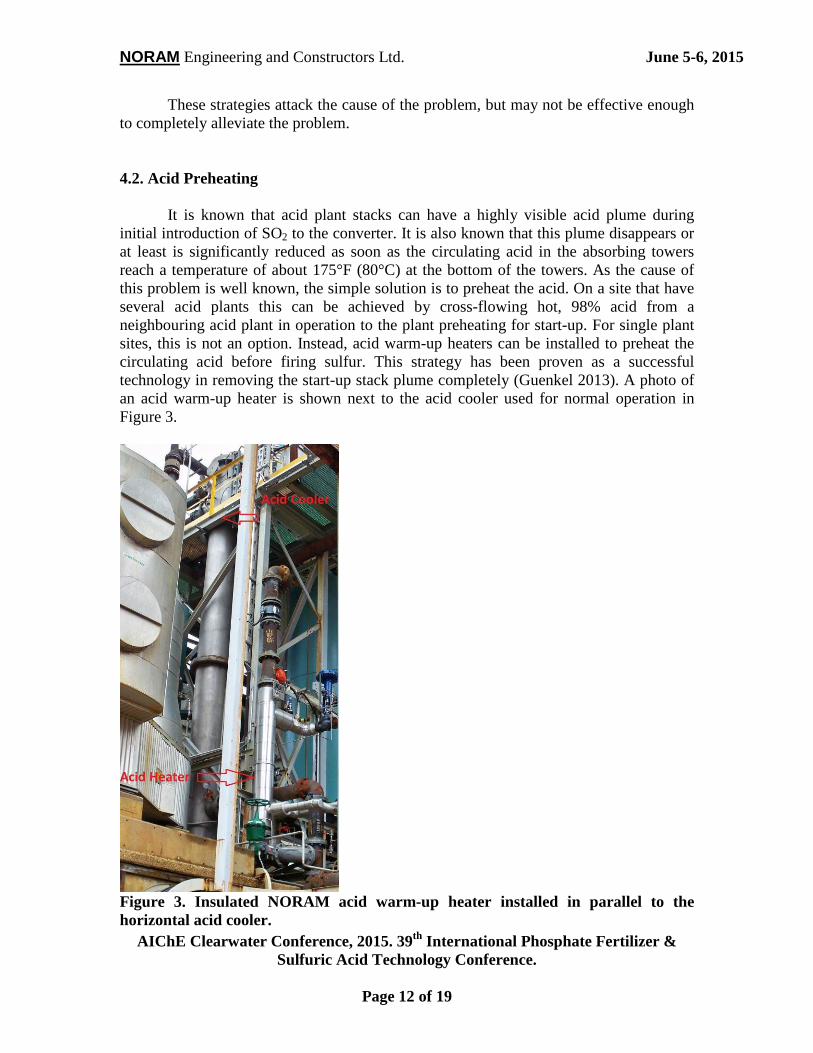
These strategies attack the cause of the problem, but may not be effective enough to completely alleviate the problem. 4.2. Acid Preheating It is known that acid plant stacks can have a highly visible acid plume during initial introduction of SO2 to the converter. It is also known that this plume disappears or at least is significantly reduced as soon as the circulating acid in the absorbing towers reach a temperature of about 175°F (80°C) at the bottom of the towers. As the cause of this problem is well known, the simple solution is to preheat the acid. On a site that have several acid plants this can be achieved by cross-flowing hot, 98% acid from a neighbouring acid plant in operation to the plant preheating for start-up. For single plant sites, this is not an option. Instead, acid warm-up heaters can be installed to preheat the circulating acid before firing sulfur. This strategy has been proven as a successful technology in removing the start-up stack plume completely (Guenkel 2013). A photo of an acid warm-up heater is shown next to the acid cooler used for normal operation in Figure 3.
Figure 3. Insulated NORAM acid warm-up heater installed in parallel to the horizontal acid cooler.

NORAM Engineering and Constructors Ltd. June 5-6, 2015
AIChE Clearwater Conference, 2015. 39th International Phosphate Fertilizer & Sulfuric Acid Technology Conference.
Page 13 of 19
4.3. Acid Aerosol Removal If the two strategies discussed in section 4.1 and 4.2 are not acceptable to the operator, or do not achieve the desired result, then the following methods can be considered to remove the acid aerosols resulting from the emission of SO3 gas. 4.3.1. WESP Wet Electrostatic Precipitators (WESP) are one of the most efficient technologies available to remove sub-micron sulfuric acid aerosols. The incoming gas containing the SO3 is prequenched with water/weak acid to cool and saturate the gas with water. In this prequench stage the SO3 gas reacts with H2O to form sulfuric acid aerosols, which are easily removed by the WESP by >99% efficiency. However, WESPs are fairly expensive and are not likely to be an economic solution for solving a start-up problem that last in the order of hours per year. Furthermore, WESP will not have any additional benefits in the removal of SO2. 4.3.2. Brownian Diffusion Mist Eliminators Brownian diffusion mist eliminators are high efficiency sub-micron aerosol separation filters. As such they may be employed to efficiently abate the acid mist start-up plume from the main stack or from the start-up vents during preheating. As seen in Figure 4, Brownian diffusion filters can remove more than 90% of sub-micron aerosols in the range 0.2-0.4 micron, and more than 98% of a typical, total distribution of acid aerosols and mist.
For plants that are lucky enough to already have Brownian diffusion candles (BD candles) in the final absorption tower, small modifications to the equipment should suffice to make them work as “start-up plume eliminators”.
As discussed in section 2.4, the cold acid irrigating the absorption towers during
start-up may become surface saturated with SO3 during start-up allowing SO3 slippage until the acid heats up. In addition, increased acid/oleum aerosols formation can be expected due to shock cooling of the hot gas while the acid is cold and if the acid concentration is not optimal, e.g. lower than 98 wt% H2SO4. Hence, during start-up there will probably be increased rates of both non-absorbed SO3 gas and sub-micron aerosols.
BD candles will remove the majority of the sub-micron aerosols formed in the tower irrespectively of whether they are irrigated or not. If not irrigated, the BD candles will also become saturated with SO3 and slip SO3 gas, due to the cold acid temperature and because they catch the oleum aerosols generated at the inlet to the cold tower.

NORAM Engineering and Constructors Ltd. June 5-6, 2015
AIChE Clearwater Conference, 2015. 39th International Phosphate Fertilizer & Sulfuric Acid Technology Conference.
Page 14 of 19
Figure 4. Collection efficiency for a typical Brownian diffusion device (Louie 2008).
However, if the BD candles can be continuously wetted with 98% acid, they will
become efficient SO3 scrubbing devices, due to the high wetted surface area and intimate contact with the flowing gas through the candles compared to the lower surface area and gas contact of the packing in the tower. The key to removing SO3 at start-up with candles is to make sure the BD candles are saturated with acid, and preferably warm, 98.5 wt% acid. This candle irrigation can be implemented either with spray nozzles located at the tubesheet inlet to standing candles or with spray nozzles located above from the top of hanging candles. There are also more robust pre-wetting systems available as shown in Figure 5. In this proven candle prewetting system, the acid flow should be started prior to the introduction of SO2 to the converter, to make sure all candles are saturated with flowing acid.
Figure 5. Hanging Brownian diffusion mist eliminator candle prewetting system. Fresh acid fed to a ring distributor sitting above the fiber matrix on each candle (Courtesy of Begg Cousland Envirotec Ltd., 2015).

NORAM Engineering and Constructors Ltd. June 5-6, 2015
AIChE Clearwater Conference, 2015. 39th International Phosphate Fertilizer & Sulfuric Acid Technology Conference.
Page 15 of 19
4.3.3. Fluidized Bed Scrubbing System The use of fluidized bed technology to perform start-up SO2 absorption was discussed in section 3.3. This technology also has merits in the abatement of particulate matter and aerosol removal, which can be achieved simultaneously with SO2 absorption in the same unit. FTL/Osprey’s patented TurboScrubber® system, licensed by NORAM, uses hollow plastic elements of varying shape, marketed as Turbofill®, Turboid® and TurboPak® depending on shape (Figure 6), and selected according to the process requirements to generate a three phase fluidized bed. This fluidized bed increases Reynolds numbers (turbulence) in the gaseous phase and the liquid phase to provide an intense enhancement of turbulent action which in turn leads to substantial increases in overall mass and heat transfer coefficients as well as interphase surface renewal rates as compared to classical packings and other scrubbing technologies. Figure 7 shows images of the fluidized bed.
Figure 6. Photos of the two main packing elements. Left: Turboid®. Right: TurboPak®.
NORAM’s TurboScrubber® System is a proven fluidized bed scrubbing
technology (over 100 installations worldwide), which allows the use of all standard scrubbing chemicals (eg. NaOH/Na2CO3, H2O2, NH3, amines, sea water), and also handles slurries such as limestone/hydrated lime (e.g. CaCO3, Ca(OH)2, Mg(OH)2). Furthermore, this fluidized bed technology has inherent particle/mist removal capabilities, which results in the possibility to remove both SO2 and acid mist/”blue smoke” in one single process unit.

NORAM Engineering and Constructors Ltd. June 5-6, 2015
AIChE Clearwater Conference, 2015. 39th International Phosphate Fertilizer & Sulfuric Acid Technology Conference.
Page 16 of 19
Figure 7. Sketch of TurboScrubber tower indicating flows and turbulent action along with an image showing the general arrangement of the TurboScrubber tower. Left: Large industrial installation. Center: Flow schematic. Right: Small scale system.
The use of fluidized bed technology, implemented as NORAM’s TurboScrubber® System, has for example been proposed for a sulfur burning plant producing up to 260 MTPD of sulfuric acid. At this plant, the stack emissions during continuous operation are approximately 180 ppmv SO2. During start-up when sulfur is first fired into the furnace this plant experiences a spike in the SO2 concentration in the stack that may exceed 1000 ppmv for several minutes, and requires the operators to shut down and re-start the plant several times during the start-up period, to be able to comply with regulatory emission requirements. Furthermore, during start-up the plant has two sources of acid mist/”blue smoke”: 1) the start-up vents during catalyst preheating, and 2) the main stack during initial sulfur firing due to cold absorber acid.

NORAM Engineering and Constructors Ltd. June 5-6, 2015
AIChE Clearwater Conference, 2015. 39th International Phosphate Fertilizer & Sulfuric Acid Technology Conference.
Page 17 of 19
The performance data in Table 2 highlights the flexibility of the TurboScrubber system. In this case study the scrubber has been sized for a SO2 removal efficiency of minimum 95% (9 ppmv SO2 in the stack) during continuous operation with only 5.8 inch W.C. pressure drop. During normal operation the system will also remove sub-micron acid mist with an efficiency of 40-55%. During start-up, when the plant gas flow is about 55% of the full capacity flow rate, and by increasing the scrubbing liquid circulation rate, the degree of turbulent mixing is increased considerably at the expense of 7 inch W.C. of pressure drop. However, this pressure drop is readily available during start-up due to the low gas flow rate. The increased turbulence of the fluidized bed results in a predicted acid mist removal of more than 94%. It is also worth noting that the increased turbulence and residence time of the scrubber increases the SO2 removal efficiency to more than 99.99% during start-up.
Due to the acid aerosol removal characteristics it is possible to use the
TurboScrubber as an “add-on” SO2 scrubbing technology without adding pressure drop to the continuously operating acid plant. This can be achieved by replacing the mist eliminator candles in the upstream sulfuric acid absorber with a mesh pad, and use only the “freed up” pressure drop for the “add-on” TurboScrubber, which will also remove sulfuric acid in addition to the SO2. Table 2. Case study of the performance of a single TurboScrubber unit during both continuous and start-up operation.
Units Continuous Start-up TurboScrubber Diameter m 1.8 Number of Turboids 32,000 Liquid Circulation Rate m3/h 82 610 SO2 Removal Efficiency > 95% > 99.99% D50 0.6 micron acid mist removal efficiency, SG 1.6 40% 94% D50 0.8 micron acid mist removal efficiency, SG 1.6 56% 99% Pressure Drop inch W.C. 5.8 12.7 D50: Mass-median-diameter. Considered as the average particle diameter by mass. SG: Specific gravity

NORAM Engineering and Constructors Ltd. June 5-6, 2015
AIChE Clearwater Conference, 2015. 39th International Phosphate Fertilizer & Sulfuric Acid Technology Conference.
Page 18 of 19
5. CONCLUSIONS During the start-up of a sulfuric acid plant there is always a potential for short term high gaseous emissions of SO2 and H2SO4. Operators are often faced with a dilemma between managers requesting full production as fast as possible and local stake holders or regulators wanting a clean and safe operation of the plant. It is the authors’ impression that the pressures from outside stake holders are becoming more important and affecting not only continuous operation, but also start-up of the sulfuric acid plant. This paper describes a typical sulfuric acid plant start-up sequence and the causes that lead to gaseous emissions of SO2 and H2SO4. A number of strategies to minimize these start-up emissions are presented. Some of these strategies attack the cause of the problem (e.g. catalyst type, converter preheating, catalyst purging, and cold start-up acid) and other strategies attack the symptoms by removing the emissions (e.g. SO2 scrubbing, and acid aerosol removal techniques). Start-up SO2 emissions can be partially reduced through catalyst selection, and flexible preheating equipment and procedures. But currently, only scrubbing can “guarantee” efficient SO2 removal. Start-up H2SO4 emissions can be effectively eliminated by the use of acid warm-up heaters or with modified Brownian diffusion mist eliminator systems in the final absorption tower. A novel fluidized bed technology solution to the sulfuric acid industry, NORAM’s TurboScrubber® system, is proposed. This is the only available technology, which can simultaneously and efficiently remove both SO2 and acid start-up emissions in one unit operation. NORAM supplies equipment to the sulfuric acid industry and has performed over 250 engineering studies associated with sulfuric acid plants. This equipment and engineering studies include solutions to start-up emission challenges.
6. ACKNOWLEDGEMENTS The authors acknowledge colleagues, operators and equipment suppliers, who contributed to this paper. Special thanks, for taking the time to discuss technical content, is given to Kevin Grigg, Sam Chidester, Kurt Christensen, Graeme Cousland and Ed Fowler.

NORAM Engineering and Constructors Ltd. June 5-6, 2015
AIChE Clearwater Conference, 2015. 39th International Phosphate Fertilizer & Sulfuric Acid Technology Conference.
Page 19 of 19
7. REFERENCES Christensen, K., Cavalca, F., Beato, P. and Helveg, S., From nano-scale studies of working sulfuric acid catalysts to improved industrial-scale sulfuric acid production. Sulfur 2014 Conference Proceedings, Paris, France, 3-6 November (2014).
Friedman, L.J. and Friedman, S. J., Proven Low Emissions from Sulfuric acid Plants with Alkali or Peroxide Systems. AIChE Clearwater Conference, 37th International Phosphate Fertilizer & Sulfuric Acid Technology Conference, (2013).
Guenkel, A. Reducing Acid Mist Emission in an Acid Plant During Cold Start-Up. Sufuric Acid Today, www.H2SO4today.com, Fall/Winter (2013).
Haldor Topsøe A/S, Improved Start-up and Flexibility using Caesium Catalyst, HaJH/HVH 07/2004, (2004).
Haldor Topsøe A/S, Manual for Topsøe’s sulphuric acid catalysts, April (2008).
Louie, D.K. Handbook of sulfuric acid manufacturing. DKL Engineering. Richmond Hill, Canada, (2008).
Micone, P., Edkins, N., Moreton, N., McIlwain, J., Reducing CAPEX and OPEX using CANSOLV-SO2 technology, AIChE Clearwater Conference, 37th International Phosphate Fertilizer & Sulfuric Acid Technology Conference, (2013).
Nikolaisen, K., Missions, D., Davis, H. and Mahecha-Botero, A., Tail Gas SO2 Scrubbing Using Fluidized Bed Technology, Sulfur 2013 Conference Proceedings, Miami, USA, 4-7 November (2013).
Puricelli, S.M., Vera-Castaneda, E., MECS SolvR Regenerative Sulfur Dioxide Technology, AIChE Clearwater Conference, 37th International Phosphate Fertilizer & Sulfuric Acid Technology Conference, (2013).
Srivastava, R.K., Controlling SO2 Emissions: A Review of Technologies, EPA Report “EPA/600/R-00/093”, November (2000).
USA EPA environmental standards, “40 CFR 60 Subpart H 60.83”, (1974).