strategies for fast-tracking conceptual plant studies ... · strategies for fast-tracking...
TRANSCRIPT

Process, Power and Marine Division
John SaninsJohn SaninsDirector, Global Business DevelopmentDirector, Global Business Development
Intergraph UK & I 200818th November 2008
SStrategies for Fasttrategies for Fast--Tracking Conceptual Tracking Conceptual Plant Studies using SmartPlant LayoutPlant Studies using SmartPlant Layout

Process, Power and Marine Division
SStrategies for Fasttrategies for Fast--TrackingTrackingConceptual Plant StudiesConceptual Plant Studies
September, 2008September, 2008
© 2008. Intergraph Corporation. All Rights Reserved. 3
Introduction Introduction ……
Conceptual Plant Engineering – Intergraph’s Perspective;– Business Drivers, Challenges & Opportunities Today …– Industry Best Practice – General Observations– Current Work Practices & Workflows – an EPC’s View– Strategy Options to support Conceptual Plant Design & Layout– Intergraph's Approach
• SmartPlant Layout Positioning & Overview• Optimized conceptual plant layout workflow
using SmartPlant Layout integratedwith Aspen Tech Applications
• Business Value
– Q & A
– Summary & Close
LayoutLayout

© 2008. Intergraph Corporation. All Rights Reserved. 4
Introduction Introduction ……
Conceptual Plant Engineering – Intergraph’s Perspective;– Business Drivers, Challenges & Opportunities Today …– Case Study; The Dow Chemical Company– Industry Best Practice – General Observations– Current Work Practices & Workflows – an EPC’s View– Strategy Options to support Conceptual Plant Design & Layout– Intergraph's Approach
• SmartPlant Layout Positioning & Overview• Optimized conceptual plant layout workflow
using SmartPlant Layout integratedwith Aspen Tech Applications
• Business Value
– Q & A– Summary & Close
LayoutLayout

© 2008. Intergraph Corporation. All Rights Reserved. 5
Business Challenges Business Challenges ……Opportunities to Change?Opportunities to Change?
““ …… over 80% of a projectover 80% of a project’’s total cost are committed withins total cost are committed withinthe first 20% of the total projectthe first 20% of the total project’’s design time s design time …”…”
Pro
fit
Time
FasterStart‐up
TraditionalStart‐up
CapitalCost Savings
FasterProfitability
IncreasedProfit
Traditional Project Cost/Breakeven Curve
Digital Plant Project Cost/Breakeven Curve
Co
st
ReducedCapital Spend
CapitalCost Savings
ConceptualDesign
DetailedDesign
Fabrication &Construction
Commission& Test Plant Operations & Maintenance
According to a Construction Industry Institute studyof 53 major projects, projects which included the most effort on conceptual plant studies averaged:
• 20% Lower Engineering costs• 39% Schedule reduction• 15% Plant Utilization/ Capacity increase
compared to projects that spent the least effort on conceptual plant design studies as part of pre-project planning.
Plant Hand-over
Plant Lifecycle
LayoutLayout
© 2008. Intergraph Corporation. All Rights Reserved. 6
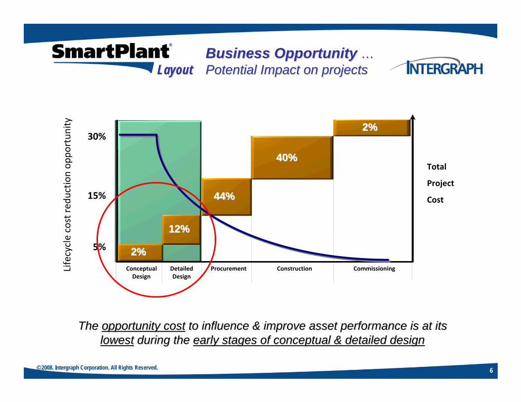
The The opportunity costopportunity cost to influence & improve asset performance is at its to influence & improve asset performance is at its lowestlowest during the during the early stages of conceptual & detailed designearly stages of conceptual & detailed design
Business Opportunity Business Opportunity ……Potential Impact on projectsPotential Impact on projectsLayoutLayout
2%2%
2%2%
40%40%
DetailedDesign
Procurement Construction CommissioningConceptualDesign
Total
Project
Cost
30%
15%
5%
12%12%
44%44%
Lifecycle cost red
uctio
n op
portun
ity

© 2008. Intergraph Corporation. All Rights Reserved. 7
User Case Study User Case Study ……
The Dow Chemical CompanyThe Dow Chemical Company

© 2008. Intergraph Corporation. All Rights Reserved. 8
Some Observations Some Observations ……From the EPC’s Perspective:
Boundaries between Conceptual Studies (traditional layout), FEED & Design continue to blur to support more fully integrated, complex projectsCommercial/ contractual basis supporting project execution strategies continues to poise challenges on projects
From the Owner/ Operator’s Perspective …Major opportunity to influence overall CAPEX/ OPEXContinued pressures to reduce schedule(time to market) & cost without any compromise to plant quality, integrity, safety & the environmentCapital Investments continue to get larger on a global scale ~ increasing number of ‘Mega-Projects’
How to manage the resulting challenges moving froma functional (PFD) to technical (P&ID) design, into plant layout …
LayoutLayout

© 2008. Intergraph Corporation. All Rights Reserved. 9
Det
aile
d D
esig
nD
etai
led
Des
ign
Det
aile
d D
esig
n
Heat & MaterialBalance
Heat & MaterialHeat & MaterialBalanceBalance
PFDPFDPFD
EvaluationEvaluationEvaluation
ProcessConfiguration& Simulation
ProcessProcessConfigurationConfiguration& Simulation& Simulation
Estimationand Cost
EstimationEstimationand Costand Cost
ProcessDatasheetsProcessProcess
DatasheetsDatasheets
EquipmentList
EquipmentEquipmentListList
An EPC View Today An EPC View Today ……Current Work Process/ Work FlowCurrent Work Process/ Work Flow
EquipmentDatasheetsEquipmentEquipmentDatasheetsDatasheets
P&ID’s 3D Plant Model

© 2008. Intergraph Corporation. All Rights Reserved. 10
Det
aile
d D
esig
nD
etai
led
Des
ign
Det
aile
d D
esig
n
Heat & MaterialBalance
Heat & MaterialHeat & MaterialBalanceBalance
PFDPFDPFD
EvaluationEvaluationEvaluation
ProcessConfiguration& Simulation
ProcessProcessConfigurationConfiguration& Simulation& Simulation
Estimationand Cost
EstimationEstimationand Costand Cost
ProcessDatasheetsProcessProcess
DatasheetsDatasheets
EquipmentDatasheetsEquipmentEquipmentDatasheetsDatasheets
P&ID’s 3D Plant Model
Solution Mapping toSolution Mapping toWork Process/ Work FlowWork Process/ Work Flow
EquipmentList
EquipmentEquipmentListList

© 2008. Intergraph Corporation. All Rights Reserved. 11
Conceptual Plant DesignConceptual Plant DesignLayout Strategies & OptionsLayout Strategies & Options
Layout Strategy Estimation Basis#1. 2D CAD-based Plot Plans Internal Rates/ Historical Data
#2. ‘Simplified’ 3D Plant Model Internal Rates/ Historical Data
#3. Integrated Process/ Plant Model Linked to Cost Estimation Software
Observations Comments 2D CAD-based Plot Plans ‘The way we’ve traditionally done it …’
Simplified 3D Plant Model ’If the customer is prepared to pay for it …’
Integrated Process/ Plant Model ‘Who will gain the overall benefits?’
Sound familiar …?
LayoutLayout

© 2008. Intergraph Corporation. All Rights Reserved. 12
Paper-based Drawing Layouts/2D Studies; Simplified 3D CAD Models
Undertaking Conceptual Plant Layouts~ Design Cases ~ using 3D plant layout toolsIntegrated with process design
CurrentApproach:
AlternateApproach:
So, Where should 3D Plant Modeling start?So, Where should 3D Plant Modeling start?
2D CAD/ Drafting & simplified 3D Modeling2D CAD/ Drafting & simplified 3D Modeling 3D Plant Design/ Modeling3D Plant Design/ Modeling
LayoutLayout
Feasibility/Concept
Feed EngineeringProcurement/Construction/ Commissioning
Operations/ Maintenance

© 2008. Intergraph Corporation. All Rights Reserved. 13
SmartPlant Layout …Intergraph’s latest solution optimized for preliminary 3D conceptual plant layout
– Early plant layout, iteration & optimization– Proposal/ tender/ RFQ/ RFP development– More accurate/ early design estimates– Not intended as a “piping designer”
Scope …Tools for optimization of plant layout;
– Layout design case management– Selected equipment, piping, structure,
space management commands– Selected local drawings and reports– Interfaces with cost estimation– Pipe Auto-Routing … Powered by Alias I-Route
IntroductionIntroductionLayoutLayout

© 2008. Intergraph Corporation. All Rights Reserved. 14
ObjectivesObjectives
Targeted at Front End Engineering DesignStarting point …
Process Flow Diagram ~ PFD
Plot size & shape ~ 2D CAD-based drawings
Facilitate layout evolution, evaluation& plant optimisation …
Plant areas & zonesEquipment placementPipe routesStructural requirements – Pipe Racks
Input to cost estimationRollover into detail design
Find the minimum evaluation cost
Avoid obstructions
Utilise Pipe Racks & Zones
LayoutLayout

© 2008. Intergraph Corporation. All Rights Reserved. 15
Simulation/ Process Design/ 3D Layout/ EstimationSimulation/ Process Design/ 3D Layout/ EstimationData Oriented Integration WorkflowData Oriented Integration Workflow
Today …
Future …
K-BaseK-Base
• PFD’s• Equipment Data Sheets• Equipment Lists (published as Equipment Data Sheets)• Stream Data Sheets (published as Equipment Data Sheets)
• 3D Model & Data • ISO Drawings• Ortho Drawings• Reports
SmartPlant3D
SmartPlant3D
P&IDs
• PFD’s• Equipment
Data Sheets• Equipment
Lists• Stream
Data Sheets
ZyqadZyqad
SmartPlantP&ID
SmartPlantP&ID
SmartPlantLayout
SmartPlantLayout
• P&IDs • Reports
• Piping MTO• Structural MTO
• Correlated P&IDs
• PFD’s• Equipment Data Sheets• Equipment Lists (published as Equipment Data Sheets)• Stream Data Sheets (published as Equipment Data Sheets)
• 3D Model & Data • ISO Drawings• Ortho Drawings• Reports
SmartPlant3D
SmartPlant3D
P&IDs
• PFD’s• Equipment
Data Sheets• Equipment
Lists• Stream
Data Sheets
ZyqadZyqad
SmartPlantP&ID
SmartPlantP&ID
SmartPlantLayout
SmartPlantLayout
K-BaseK-Base
• P&IDs • Reports
• Piping MTO• Structural MTO
• Correlated P&IDs
• Piping Data
© 2008. Intergraph Corporation. All Rights Reserved. 16
Pip
ing
Pip
ing
Str
uct
ura
lStr
uct
ura
l
Ele
ctri
cal
Ele
ctri
cal
(Cab
le T
ray)
(Cab
le T
ray)
HV
AC
HV
AC
Dra
win
gs
&D
raw
ing
s &
Rep
ort
sR
ep
ort
s
Sp
ace
Sp
ace
Man
ag
em
en
tM
an
ag
em
en
t
Eq
uip
men
tEq
uip
men
t&
Fu
rnis
hin
gs
& F
urn
ish
ing
s
Cata
log
ue
Cata
log
ue
CommonCommon
Gri
ds
Gri
ds
Han
gers
Han
gers
& S
up
po
rts
& S
up
po
rts
Syst
em
sSyst
em
s&
Sp
eci
fica
tio
ns
& S
peci
fica
tio
ns
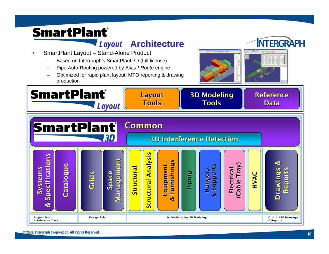
Project Setup& Reference Data
Design Aids Multi-discipline 3D Modeling Ortho/ ISO Drawings& Reports
Str
uct
ura
l A
naly
sis
Str
uct
ura
l A
naly
sis
3D Interference Detection3D Interference Detection
SmartPlant Layout – Stand-Alone Product– Based on Intergraph’s SmartPlant 3D (full license)– Pipe Auto-Routing powered by Alias I-Route engine– Optimized for rapid plant layout, MTO reporting & drawing
production
LayoutLayoutLayoutLayoutToolsTools
3D Modeling3D ModelingToolsTools
ReferenceReferenceDataData
ArchitectureArchitectureLayoutLayout

© 2008. Intergraph Corporation. All Rights Reserved. 17
Optimized SmartPlant Layout WorkspaceLayout Tools:
– Define Connections– Limit Path– Auto Route
Modeling Tools:– Place Equipment– Place Zones– Place Pipe & Components– Place Structural
Reference Data (OOTB):– Layout Equipment– Pipe Auto-router Rules– Layout Piping Specifications– Code Lists– Layout Drawing & Report Templates
Layout
Zones
Equipment
Piping
WorkflowWorkflowLayout Task/ Reference DataLayout Task/ Reference Data
User‐Configurable/Extendible
User‐Configurable/Extendible
LayoutLayout

© 2008. Intergraph Corporation. All Rights Reserved. 18
DefineSite Grid,
Plant Zones& Pipe Racks
DefineSite Grid,
Plant Zones& Pipe Racks
Create/ Position Equipment
Create/ Position Equipment
Define / ImportPipe Runs
Define / ImportPipe Runs
Auto-RoutePipe Runs
Auto-RoutePipe Runs
Adjust Layout(Optimization)
Adjust Layout(Optimization)
Document Design Case
Document Design Case
LayoutOK?
LayoutOK?
Yes
No
WorkflowWorkflowLayout Workflow/ OverviewLayout Workflow/ OverviewLayoutLayout

© 2008. Intergraph Corporation. All Rights Reserved. 19
Intelligent ‘Smart’ Grid Wizard assistsinitial site layoutDynamic creation of Pipe Racks
– Identical to SmartPlant 3D Structure
Equipment placed from SmartPlant Layout reference data catalog
– Based on identical SmartPlant 3D Equipment objects
WorkflowWorkflowDefine Site Grid, Pipe RacksDefine Site Grid, Pipe Racks& Zones; Position Equipment& Zones; Position EquipmentLayoutLayout

© 2008. Intergraph Corporation. All Rights Reserved. 20
Piping can be placed in the 3D modelfrom various sources;
– SmartPlant P&ID• Import of line connection data & correlation
– 3D Model• User routes piping & then applies rules• Auto-routing pipe
– Spreadsheet• Import of line & connection data from Excel
Connectivity between;– Equipment origins– Equipment bounding boxes– Equipment nozzles– 3D points– Connection zones– Runs
WorkflowWorkflowDefine & Import Pipe RunsDefine & Import Pipe RunsLayoutLayout

© 2008. Intergraph Corporation. All Rights Reserved. 21
Goal is to find the minimum cost route while avoiding obstructions …
… resulting route driven by space objects(3D volumes& zones) initially created in theSmartPlant Layout 3D model …
- 3D Volumes & Zones(with special attributes)
• Attraction• Pipe Rack
– ‘Via’ zones• Avoidance• Connection
– Obstructions– SmartPlant Layout 3D Plant Objects
Pipe AutoPipe Auto--router Theoryrouter Theory
User‐Configurable/Rules
User‐Configurable/Rules
LayoutLayout

© 2008. Intergraph Corporation. All Rights Reserved. 22
Vessel
Equipment
#5. Attraction Zone#6. Via Zone
#4.Avoidance
Zone
#1. Connection Zone #2. PipeRack Zone
#3.Interference Volume
RulesRules‘‘ForcingForcing’’ the Routethe Route
#7. SmartPlant Layout 3D Plant Objects
LayoutLayout
© 2008. Intergraph Corporation. All Rights Reserved. 23
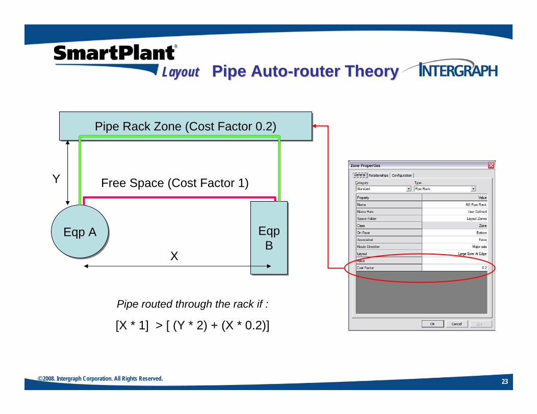
Pipe Rack Zone (Cost Factor 0.2)Pipe Rack Zone (Cost Factor 0.2)
Eqp AEqp A EqpB
EqpB
Free Space (Cost Factor 1)
X
Y
Pipe routed through the rack if :
[X * 1] > [ (Y * 2) + (X * 0.2)]
Pipe AutoPipe Auto--router Theoryrouter TheoryLayoutLayout

© 2008. Intergraph Corporation. All Rights Reserved. 24
Auto-router defines minimum cost routes, while …– Complying with defined zones– Avoiding obstructions– Complying with rules
Routes driven by space elements in 3D model …– Zones
• Attraction• Pipe Rack• Avoidance• Connection
– Other obstructions/objects
Routes driven by rules …– Branch gap– Air gap– Standout– Etc.
PipeAir Gap
Standout
Branch Gap
WorkflowWorkflowAutoAuto--Route Pipe RunsRoute Pipe RunsLayoutLayout

© 2008. Intergraph Corporation. All Rights Reserved. 25
Branch Gap
• Branch GapThe separation between adjacent branches connecting to the same header. If the branch gap value is greater than the in line length, this value will take precedence.
RulesRulesBranch GapBranch GapLayoutLayout

© 2008. Intergraph Corporation. All Rights Reserved. 26
= a Routing Parameter
• Pipe Air GapThe separation required between adjacent pipes.If the Piping Materials Class has butt welded joints, the nominal pipe diameter (NPD) & this value determines the pipe separation.Where adjacent pipes have different NPD sizes, the separation is half that for pipe 1 plus half that for pipe 2.
Pipe Air Gap
RulesRulesPipe Air GapPipe Air GapLayoutLayout

© 2008. Intergraph Corporation. All Rights Reserved. 27
Standout10cm + Min Pipe
Length
RulesRulesStandoutStandoutLayoutLayout

© 2008. Intergraph Corporation. All Rights Reserved. 28
Pipe Specs Pipe Specs Piping PartsPiping Parts
Can be either SmartPlant Layout specific specsCan be either SmartPlant Layout specific specsor or ““standardstandard”” SmartPlant 3D SpecsSmartPlant 3D Specs
• Defines Piping Specifications used in Layout… ‘Generic’ ~ limited ~ specifications of basic piping components
RulesRulesLayout Piping SpecificationLayout Piping SpecificationLayoutLayout

© 2008. Intergraph Corporation. All Rights Reserved. 29
Rack SpacingRack Spacing Cost FactorsCost Factors
• Defines spacing of pipes… Defines cost factors – straight vs. bends
RulesRulesRack Spacing & Cost FactorsRack Spacing & Cost FactorsLayoutLayout

© 2008. Intergraph Corporation. All Rights Reserved. 30
Allows definition of Layout Equipment, its dimensions, Allows definition of Layout Equipment, its dimensions, location & orientation for use in alternate scenarioslocation & orientation for use in alternate scenarios
• Defines Equipment in Layout… can be saved and reused
RulesRulesLayout EquipmentLayout EquipmentLayoutLayout

© 2008. Intergraph Corporation. All Rights Reserved. 31
WorkflowWorkflowInitial Starting PointInitial Starting Point
Initial Layouts & Sketches~ P&ID & Plan Layout
Initial ‘Intelligent’ SmartPlant P&ID
LayoutLayout
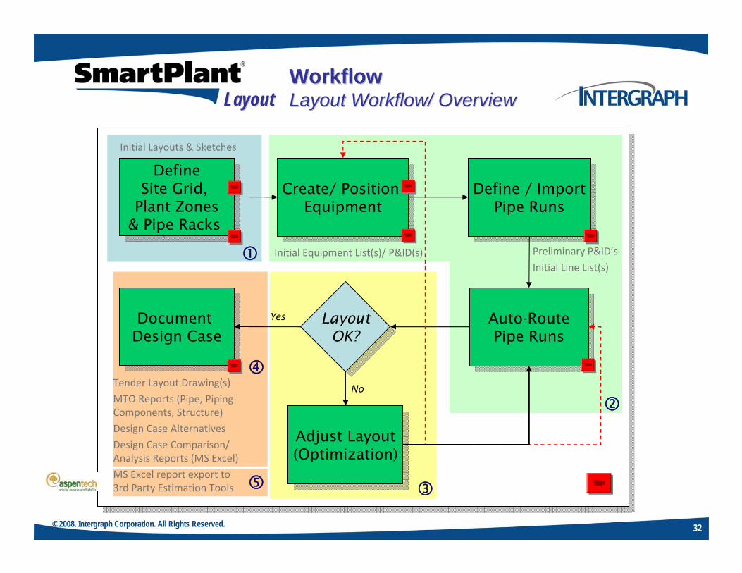
© 2008. Intergraph Corporation. All Rights Reserved. 32
DefineSite Grid,
Plant Zones& Pipe Racks
DefineSite Grid,
Plant Zones& Pipe Racks
Create/ Position Equipment
Create/ Position Equipment
Define / ImportPipe Runs
Define / ImportPipe Runs
Auto-RoutePipe Runs
Auto-RoutePipe Runs
Adjust Layout(Optimization)
Adjust Layout(Optimization)
Document Design Case
Document Design Case
LayoutOK?
LayoutOK?
Yes
NoTender Layout Drawing(s)
MTO Reports (Pipe, Piping Components, Structure)
Design Case Alternatives
Design Case Comparison/Analysis Reports (MS Excel)
MS Excel report export to3rd Party Estimation Tools
Initial Equipment List(s)/ P&ID(s) Preliminary P&ID’s
Initial Line List(s)
Initial Layouts & Sketches
WorkflowWorkflowLayout Workflow/ OverviewLayout Workflow/ OverviewLayoutLayout

© 2008. Intergraph Corporation. All Rights Reserved. 33
Optimize layout through adjustments to site grid(s), pipe racks, zones& equipment positionAlternatives (Design Cases) for equipment & volume position- parameters can be saved & recalledResults can viewed …
– On-screen– Via intelligent orthographic drawings– Via intelligent reports
Direct integration via SmartPlant Review for layoutwalk-thru. & visualization
Output for cost estimation;Aspen Icarus™ (Kbase)
– Pipe/ Fittings– Steel
WorkflowWorkflowOptimization/ Case ManagementOptimization/ Case Management
COST ESTIMATIONKbase
LayoutLayout

© 2008. Intergraph Corporation. All Rights Reserved. 34
SmartPlant Layout 3D data (MS Excel reports) are importedinto Aspen Technology’s Kbase for cost evaluation
WorkflowWorkflowCost Estimation with KbaseCost Estimation with Kbase
SmartPlantLayoutLine ListReport
LayoutLayout

© 2008. Intergraph Corporation. All Rights Reserved. 35
Speed & quality improvements compared tomanually drafted layouts;
– Improved preliminary designs– Increased estimate accuracy based on actual
layout– Higher Quailty Proposals
leading to …
10% reduction in concept development man-hours90% reduction in material estimate man-hours10-20% reduction in detailed design manhours5-10% reduction in total plant installed costReduction in materials requirements
ValueValueConceptual Plant Layout Benefits Conceptual Plant Layout Benefits
SmartPlant Layout SmartPlant Layout –– Design Layout Design Layout (Case) (Case) AlternativesAlternatives
LayoutLayout
SmartPlant Layout Customer Comments:
“… Strong points include compatibility with SmartPlant 3D, user‐friendliness & easy to configure & learn …”
“… a good replacement for our current 3D plant layout solution …”
“… the equipment task, input definition of pipeline data, rules setup & connectivity were easy to use ”
“ …no other product on the market today (is capable of) producing a FEED model from withina detailed design solution integrated to process & cost estimating tools …”

© 2008. Intergraph Corporation. All Rights Reserved. 36
Summary & CloseSummary & Close

© 2008. Intergraph Corporation. All Rights Reserved. 37
SummarySummary
SmartPlant Layout is a new, standalone solution for conceptual 3D plant layout & designfor use by the EPC OR the Plant Owner!
Preliminary 3D plant layout benefits are well documented compared to manual methods …
– Significant modeling/ layout productivity– Data integration,– Layout optimization– Conceptual layout quality improvements
When integrated with SmartPlant 3D &SmartPlant P&ID …
SmartPlant Layout delivers furtherincremental benefits to your projects …
– Conceptual/ preliminary designs seamlesslyevolve into early detailed design phase
– Improved preliminary cost estimates– Over 85% reduction in re-modeling man-hours
during the conceptual design phase– Over 90% reduction in model data reuse from
proposal to initial detailed design phase of project– Improved design quality – Lower administrative burden
LayoutLayout

Process, Power and Marine Division
Integrating the Engineering Enterprise…