strain controlled tests on glass fiber reinforced...
TRANSCRIPT

STRAIN CONTROLLED TESTS ON GLASS FIBER REINFORCED PLASTICS
Razvan Natanail 1, Ioan Bondrea 2
1 Lucian Blaga University Sibiu [email protected] 2 Lucian Blaga University Sibiu, [email protected]
Keywords: composite, glass-fiber, GFRP, LCF. Abstract: The objective of the present investigation is the experimental determination of the material properties for application of the local strain concept. This concept is mainly applied for the design of engineering structures which are subjected to time dependant variable loads which are causing elastic-plastic stress-strain-cycles in the high stressed spots during the operation of the structure. The investigations relate to two different glass-fiber reinforced plastics. The materials differ mainly in the arrangement of the fibers: amorphous and multi-axial layers (+/- 45).
1. INTRODUCTION
High-stress low-cycle fatigue characterization of plastic composites have become of
interest to design engineers due to the increased utilization of plastics in structural elements. The shortages regarding the development time for the realization of high performance and at the same time economical cars require reliable knowledge about the properties of the used materials. The continuing trend towards premium performance of modern cars has a significant increase in the mechanical and thermal load of components.
The rapidly increasing use of glass fiber reinforced plastics (GFRP) in recent years has brought about the need for greater knowledge of their behavior under load. Glass fiber reinforced plastics are generally more sensitive to fatigue loading than are composites based on high modulus fibers [2].
The assurance and maintenance of the safety and integrity of structures is one of the most important tasks in engineering. Numerous catastrophic failures that have occurred in the past have proved that this demand has to be given higher priority. An important reason for failures is the limitation of the actual knowledge (state of the art) in the field of strength of materials especially in the subject of fatigue.
The design concepts for the assessment of the structural durability are derived from the stress categories in structures:
Primary membrane, bending and torsion stresses
Secondary stresses (Structural stresses)
Peak stresses or strains at notched regions
Stress intensities near crack like defects. Basis of the local concepts are based on the assumption that the local stress- strain-
history in the highest stressed portion of a structure is decisive for the failure and hence also for the lifetime of the structure.
The local stress state may be linear elastic or elastic plastic. For the linear elastic behavior the stresses can be used as damage parameters (Local Stress Concept) whereas in the plastic regime the strains are the cause for the failure (Local Strain Concept).
In contrast to the Nominal Stress Concepts which normally describes the life up to fracture, the failure criteria in the local concepts is crack initiation. So the lifetime calculation can be carried out in two stages: application of the local concepts followed by fracture mechanics.
An overview of the structure of the Local Strain Concept (LSC) is shown in figure 1. The input is cyclic material data obtained from un-notched standard specimen. The load-time-history has to be transferred into local stress-strain-loops in the notch which is mainly
ANNALS of the ORADEA UNIVERSITY.
Fascicle of Management and Technological Engineering, Volume X (XX), 2011, NR2
4.73

obtained by applying the Rainflow Counting method with consideration of few special laws. The comparison of the Low-Cycle-Fatigue (LCF)-curve and the notch cycles leads to the damage calculation which is as well based on Miner-Palmgren-Rule.
Figure 1. Principle of Local Strain Concept [1]
The results of the LCF-tests are plotted in strain-amplitude as a function of the
number of cycles to crack initiation. The numerical expression of the LCF-curve according to the famous Manson-Coffin-equation is the sum of elastic and the plastic strain, see figure 2.
The intersection of the elastic and the plastic line is often used as separation between the LCF- and High Cycle Fatigue (HCF)-regime.
Figure 2. Low- Cycle- Fatigue (LCF) Curve, Manson- Coffin. Equation [1]
For the description of the cyclic stress-strain-function, the so called stabilized loop is
used which is the stress-strain-loop recorded at 50 % of the crack initiation cycles. The cyclic stress-strain-loop differs from the monotonic stress-strain-loop that is recorded in tensile tests.
ANNALS of the ORADEA UNIVERSITY.
Fascicle of Management and Technological Engineering, Volume X (XX), 2011, NR2
4.74

The difference between the cyclic and the monotonic stress-strain-loops is governed by the individual material behavior, which can be classified into:
cyclic hardening materials
cyclic softening materials
neutral materials. The Ramberg-Osgood-Law is used for the numerical approximation of the cyclic
stress-strain-loop, which is again a sum of the elastic and the plastic part, figure 3. The constants E, K' and n' can be obtained by regression analysis in double-log-presentation of the experimental results.
Figure 3. Eyuation of cyclic stress- strain- curve [1]
The damage caused by each cycle is expressed by a damage parameter which
includes the strain amplitude and the influence of the level of the loop. The mostly used damage parameter is the parameter proposed by Smith/Watson and Topper (SWT).
2. EXPERIMENTAL METHODS
The investigations relate to two different glass-fiber reinforced plastics. Our project partner, the vehicle manufacturer, Binz selected the materials and the company PB Composite produced them. The materials differ mainly in the arrangement of the fibers: amorphous and +/- 45° multi-axial layer (figure 4).
Figure 4. Scanning electron microscope (SEM) picture of the top layers of the tested materials
The material used for the LCF study was in the form of laminated plates. The
amorphous +/- 45° multi-axial layer
Filler
Glass Fibers
Epoxy Resin
Gel Coat
Filler
Glass Fibers
Epoxy Resin Gel Coat
ANNALS of the ORADEA UNIVERSITY.
Fascicle of Management and Technological Engineering, Volume X (XX), 2011, NR2
4.75

samples have a top and bottom layer of 600 g/cm² of glass fiber and a epoxy resin system 285 of the firm Lange and Ritter. The rest of the specimen is filled with special filler with micro-balloons. The range of fiber volume fraction for the tested laminates was found to be 0.1. The top and bottom layers have a fiber volume ratio of 0.25. The shape and dimensions of the specimens used for the experiments are shown in figure 5. The specimens have a original thickness of 5 mm, a wide of 30 mm and a shaft of 90 mm. Un-notched specimens (Kt = 1.0) were tested. A special clamping facility was build for the tests see figure 6.
Figure 5. Geometry of specimens
Figure 6. CAD- drawing of clamping facility
Quasistatic tensile tests have been carried out at room temperature (20°C) under
displacement control on a 100-kN-testing machine, type Zwick. In order to determine Youngs modulus, which is a decisive parameter for the evaluation of the LCF-tests, 3 specimens have been loaded in the linear elastic range with 3 cycles each. In order to determine the standard tensile properties the specimens have been loaded up to fracture.
The LCF-test have been carried out on a servohydraulic test frame, type MTS, see figure 7. The software MTS Cyclic Fatigue Test Star, Version 4.6, has been used for the conduction and evaluation of the tests. The 20-kN-cylinder is direct integrated in the test rig. The strain was measured and controlled by an extensometer.
ANNALS of the ORADEA UNIVERSITY.
Fascicle of Management and Technological Engineering, Volume X (XX), 2011, NR2
4.76
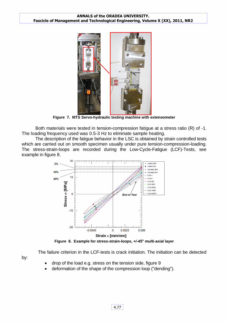
Figure 7. MTS Servo-hydraulic testing machine with extensometer
Both materials were tested in tension-compression fatigue at a stress ratio (R) of -1.
The loading frequency used was 0.5-3 Hz to eliminate sample heating. The description of the fatigue behavior in the LSC is obtained by strain controlled tests
which are carried out on smooth specimen usually under pure tension-compression-loading. The stress-strain-loops are recorded during the Low-Cycle-Fatigue (LCF)-Tests, see example in figure 8.
Figure 8. Example for stress-strain-loops, +/-45° multi-axial layer
The failure criterion in the LCF-tests is crack initiation. The initiation can be detected
by:
drop of the load e.g. stress on the tension side, figure 9
deformation of the shape of the compression loop ("dending").
ANNALS of the ORADEA UNIVERSITY.
Fascicle of Management and Technological Engineering, Volume X (XX), 2011, NR2
4.77
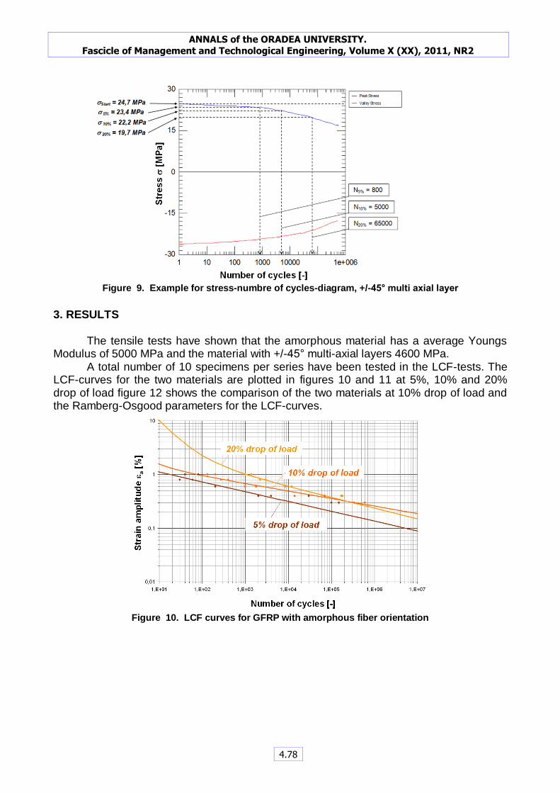
Figure 9. Example for stress-numbre of cycles-diagram, +/-45° multi axial layer
3. RESULTS
The tensile tests have shown that the amorphous material has a average Youngs Modulus of 5000 MPa and the material with +/-45° multi-axial layers 4600 MPa.
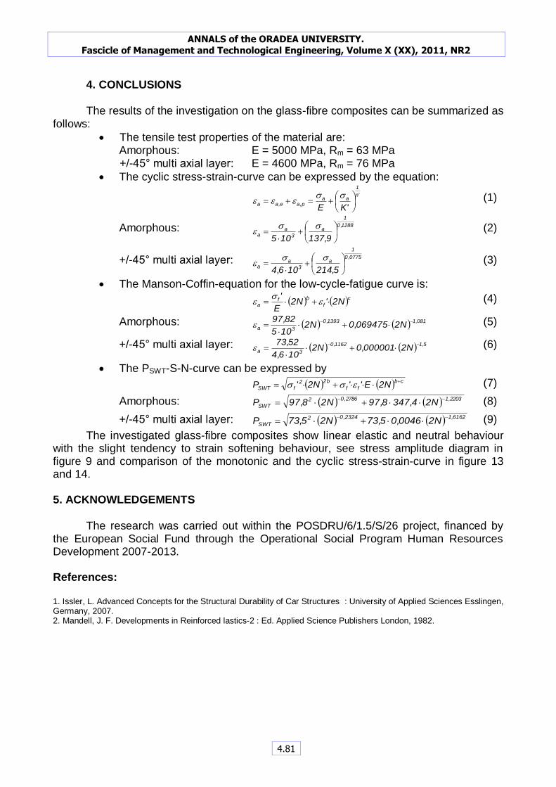
A total number of 10 specimens per series have been tested in the LCF-tests. The LCF-curves for the two materials are plotted in figures 10 and 11 at 5%, 10% and 20% drop of load figure 12 shows the comparison of the two materials at 10% drop of load and the Ramberg-Osgood parameters for the LCF-curves.
Figure 10. LCF curves for GFRP with amorphous fiber orientation
ANNALS of the ORADEA UNIVERSITY.
Fascicle of Management and Technological Engineering, Volume X (XX), 2011, NR2
4.78

Figure 11. LCF curves for GFRP with +/-45° multi-axial layer
Figure 12. Comparison of LCF curves at 10% drop of stress
The definition for cack initiation is a drop of 10 % of the maximum stress. The
comparison of the monotonic and cyclic curves is plotted in figures 13 and 14.
Manson-Coffin GFK B_10%
sf' [MPa] 73,52
b [-] -0,1162
ef' [m/m] 0,000001
c [-] -1,5000
E [GPa] 4,6
Manson-Coffin GFK A_10%
sf' [MPa] 97,82
b [-] -0,1393
ef' [m/m] 0,069475
c [-] -1,0810
E [GPa] 5
ANNALS of the ORADEA UNIVERSITY.
Fascicle of Management and Technological Engineering, Volume X (XX), 2011, NR2
4.79

Figure 13. Comparison of monotonic and cyclic curve for GFRP with amorphous fiber orientation
Figure 14. Comparison of monotonic and cyclic curve for GFRP with +/-45° multi-axial layers
The fatigue studies have shown that high-cycle fatigue life is dominated by fatigue
cracking in the matrix that subsequently propagate and rupture the fibers. Once a significant number of fibers fracture, the composite laminate fails shortly thereafter.
Ramberg-
Osgood
cyclic
GFK A_10%
K' [MPa] 137,92
n' [-] 0,1288
E [GPa] 5
Ramberg-
Osgood
cyclic
GFK B_10%
K' [MPa] 214,45
n' [-] 0,0775
E [GPa] 4,6
ANNALS of the ORADEA UNIVERSITY.
Fascicle of Management and Technological Engineering, Volume X (XX), 2011, NR2
4.80
4. CONCLUSIONS
The results of the investigation on the glass-fibre composites can be summarized as
follows:
The tensile test properties of the material are: Amorphous: E = 5000 MPa, Rm = 63 MPa
+/-45° multi axial layer: E = 4600 MPa, Rm = 76 MPa
The cyclic stress-strain-curve can be expressed by the equation:
'n
1
aap,ae,aa
'KE
sseee (1)
Amorphous: 1288,0
1
a
3
aa
9,137105
sse (2)
+/-45° multi axial layer: 0775,0
1
a
3
aa
5,214106,4
sse (3)
The Manson-Coffin-equation for the low-cycle-fatigue curve is:
cf
bfa N2'N2
E
' e
se (4)
Amorphous: 081,11393,0
3a N2069475,0N2105
82,97
e (5)
+/-45° multi axial layer: 5,11162,0
3a N2000001,0N2106,4
52,73
e (6)
The PSWT-S-N-curve can be expressed by
cb
ff
b22
fSWT N2E''N2'P
ess (7)
Amorphous: 2203,12786,02
SWT N24,3478,97N28,97P
(8)
+/-45° multi axial layer: 6162,12324,02
SWT N20046,05,73N25,73P
(9)
The investigated glass-fibre composites show linear elastic and neutral behaviour with the slight tendency to strain softening behaviour, see stress amplitude diagram in figure 9 and comparison of the monotonic and the cyclic stress-strain-curve in figure 13 and 14. 5. ACKNOWLEDGEMENTS
The research was carried out within the POSDRU/6/1.5/S/26 project, financed by
the European Social Fund through the Operational Social Program Human Resources Development 2007-2013. References:
1. Issler, L. Advanced Concepts for the Structural Durability of Car Structures : University of Applied Sciences Esslingen, Germany, 2007. 2. Mandell, J. F. Developments in Reinforced lastics-2 : Ed. Applied Science Publishers London, 1982.
ANNALS of the ORADEA UNIVERSITY.
Fascicle of Management and Technological Engineering, Volume X (XX), 2011, NR2
4.81