stove - dunbrik flues · height above the last support of up to 1.5 metres, subject to the ......
TRANSCRIPT

Twin Wall Flue
Economical twin wall, insulated stainless steel chimney system for wood burning/multi fuel stoves 100% Manufactured
in the UK
SflueTOVE
SflueTOVE

2 3
IntroductionThe Sflue family of products has been specifically designed to meet the requirements for multi-fuel appliances that operate under negative or neural draught conditions. Under no circumstances should Sflue be used on appliances that generate high levels of condensation or positive pressure within the chimney system. For such systems our NOVA® product should be used. With a specific range of components and a multi-barb twist-lock jointing system, Sflue offers the ultimate in ease of installation and quality at a competitive price. Sflue is a CE approved product and has been tested to the requirements of BS EN 1856-1, see Table 1 - Chimney designation.
DescriptionSflue is a prefabricated, factory made twin-wall insulated stainless steel system chimney. The fully welded construction combined with a high performance / high density insulating medium, provides the optimum level of performance required for modern-day solid fuel appliances such as DEFRA approved high-efficiency wood-burners alongside traditional stove installations.
The construction provides a high thermal resistance which ensures rapid stabilisation of the flue gas temperature and draught, whilst maintaining a relatively low temperature on the external surface of the chimney. Sflue is designed for internal and external applications, suitable for negative pressure applications.
Sflue utilises an eight-barb quick lock jointing system to secure each joint. The components are secured by locating the barbs with a twist of each section. A locking band must then be used at each joint. The joint design facilitates a maximum unsupported height above the last support of up to 1.5 metres, subject to the design considerations detailed within the Installation Instructions and on page 14 of this brochure.
Sflue is manufactured from a high grade 316L (1.4404 : X2CrNiMo 17-12-2) stainless steel liner and a 304 (1.4301 : X5CrNiMo 18-10-2) outer case. The product utilises a high performance mineral wool which is auger injected into a 25mm annulus between the inner and outer to a mean density of 250kg/m3, offering rapid stabilisation of draught and excellent thermal performance. The unique joint design allows the inner liner to freely expand and contract throughout the system as the flue gas temperature varies, alleviating the need for additional expansion components.
ApplicationSflue is available in four internal diameters ranging from 127mm to 203mm and is suitable for solid fuel applications operating under negative draught / dry conditions or where the maximum positive pressure will not exceed 40Pa as designated by N1, at a maximum flue gas temperature of 450°C.
When used for solid fuel where the flue gas temperature is greater than 250°C and passing through a combustible floor, the ventilated support components must be used as detailed on page 14.
Sflue product designations to BS EN 1856-10086-CPD-496040 Sflue BS EN 1856-1 T450 N1 D Vm L50040 G(50)
Standard number
Temperature class
Pressure class
Condense resistance D=dry W=wet
Corrosion class
Material specification Liner grade 316L Liner thickness: 0.4mm
Sootfire resistance G=yes O=no
Table 1 - Chimney designation to BS EN 1856-1
TerminalsPage 8
Storm CollarPage 9
FlashingPage 11/12
Rafter SupportPage 6
Ventilated FirestopPage 5
Ventilated Ceiling SupportPage 5
Appliance/Single Wall AdaptorPage 7
ElbowPage 4
Wall BandPage 6
TeePage 5
Wall SupportPage 6
Wall SleevePage 9
Tee CapPage 5
Trim CollarPage 9

4 5
B
B
A
A
C
B
Standard VentilatedCeiling Support
Solid fuel and oil fired appliance (T450)The following components MUST be used where Sflue is used on solid fuel or oil fired appliances where the flue gas temperature will not exceed 450°C and /or where the chimney system penetrates a combustible floor. Each ventilated component offers a 50mm clearance to combustible materials.
Standard Ventilated Ceiling Support (T450)Used to both support and firestop the chimney system when it passes through the first combustible floor directly above the appliance. The support component incorporates a patented intumescent matrix design which expands rapidly with temperature and seals the plate to prevent the potential spread of fire or smoke from the room below.
ø A B C Code127mm 361 281 379 2172705152mm 381 301 399 2172706178mm 411 331 429 2172707203mm 431 351 453 2172708
For painted variations add the following letters after the part number:- White: ZW
Ventilated Firestop (T450)Used where the chimney passes through the upper combustible floors and where sections below the floor are enclosed within a non combustible shaft. This item is non load-bearing.
ø A B Code127mm 281 379 2188705152mm 301 399 2188706178mm 331 429 2188707203mm 355 453 2188708
For basic installation information concerning floor-
penetrations, please see page 14 of this brochure
B
B
A
A
C
B
Ventilated Firestop
Straight LengthAvailable in nominal installed lengths of 1000mm, 500mm, 300mm & 120mm.
Installed Length
120mm 300mm 500mm 1000mm
ø Code Code Code Code127mm 2110605 2141105 2141005 2140905152mm 2110606 2141106 2141006 2140906178mm 2110607 2141107 2141007 2140907203mm 2110608 2141108 2141008 2140908
Adjustable LengthThe two-part adjustable length offers a degree of flexibility when standard length dimensions are not suitable. All adjustable lengths are supplied with separate insulating material for insertion into the annulus once the installed length has been determined.
As the insulation density is installed on site and not controlled by SFL, we recommend that this component is located at least 300mm from any combustible material.
Type Short (200mm - 325mm) Long (350mm - 530mm)
ø Code Code
127mm 2144005 2141205
152mm 2144006 2141206
178mm 2144007 2141207
203mm 2144008 2141208
Inspection LengthA 500mm length incorporating a removable door for inspection/cleaning
ø Code
127mm 2141805
152mm 2141806
178mm 2141807
203mm 2141808
2 Segment Elbows (15°, 30°, 45°)Provides a change of direction, measured from the vertical by the specified angle. See technical data on page 15 for dimensions. Elbows are supplied with an unbarbed female coupler and screw-toggle type locking band for rigid joint bracing, especially when used as an offset around gutters and fascia boards.
Angle 15° 30° 45°
ø Code Code Code127mm 2131405 2132305 2132205152mm 2131406 2132306 2132206178mm 2131407 2132307 2132207203mm 2131408 2132308 2132208
Three-segment 90° ElbowsProvides a change of direction of 90° and counts as two 45° elbows where used in a solid fuel system according to building regulations approved document J (Part F for Scotland). Can also be used under the alternative installation instructions as detailed in BS EN 15287-1
Dimension (mm)
ø A B C Code127mm 87 126 148 2145305152mm 92 136 157 2145306178mm 97 144 165 2145307203mm 102 156 174 2145308
A
A
B
C
TEES / FLOOR PENETRATION
Tee Cap with DrainUsed at the bottom of a vertical chimney to facilitate drainage. Fitted with a stainless steel 1” BSP external thread drain connection.
ø Code127mm 2153205152mm 2153206178mm 2153207203mm 2153208
TEE COMPONENTS
Tee CapUsed to close off the branch or base of a tee or for use as an access/inspection component.
ø Code127mm 2119105152mm 2119106178mm 2119107203mm 2119108
A
B
B
A
B
A
B
C
D
90° Equal TeeUsed as the entry to a vertical chimney from a horizontal stove outlet or as an inspection opening.
Dimension (mm)
ø A B Code127mm 300 150 2114305
152mm 325 162 2114306
178mm 350 175 2114307
203mm 375 187 2114308
135° TeeUsed at the base of a vertical chimney, or to allow a smooth transition from the horizontal to vertical plain when used with a 45° elbow. The coupler on the branch is unbarbed to allow unlimited rotational adjustment and provided with an adjustable screw-toggle locking band.
Dimension (mm)
With 45° Elbow
ø A B C D Code127mm 495 340 388 38 2141305152mm 495 375 422 45 2141306178mm 745 420 463 54 2141307203mm 745 450 492 60 2141308
TEES
LENGTHS & ELBOWS
FLOOR PENETRATION

6 7
A
B
A
B
Ceiling Support
Firestop Spacer
A
Non-combustible floors The following components MUST be used on gas or oil fired appliances where the flue gas temperatures does not exceed 250°C and / or where the chimney passes through a non-combustible floor.
Ceiling SupportProvides a 50mm air gap clearance to a penetrated floor or ceiling and is only used where Sflue penetrates a non-combustible floor, and / or services a gas or oil fired appliance where the flue gas temperature does not exceed 250°C
ø A B Code127mm 330 280 2102705152mm 355 305 2102706178mm 381 331 2102707203mm 406 356 2102708
Firestop SpacerUsed to provide location, fire and dust stopping where Sflue is used through non-combustible floors, and / or serves a gas or oil fired appliance where the flue gas temperatures does not exceed 250°C. This item is not load bearing.
ø A B Code127mm 330 280 2108705152mm 355 305 2108706178mm 381 331 2108707203mm 406 356 2108708 Support length (Strut/Guy
Attachment)A 100mm installed length which incorporates a plate located 33mm from the bottom edge and features slotted holes for rotational adjustment, for fixing to bespoke bracketry. This component also doubles as a strut / guy attachment length offering anchoring points to which guys, or preferably rigid stays can be secured using M8 nuts and bolts. Manufactured from stainless steel.
ø Code127mm 2171305152mm 2171306178mm 2171307203mm 2171308
Wall Support BracketUsed to take the vertical load of the chimney when supported from a wall. The support bracket is fully adjustable allowing varying clearances from the wall (50mm as standard). Requires M10 wall fixings.
ø A B C Code127mm 282 311 265 2151705152mm 302 331 285 2151706178mm 331 360 314 2151707203mm 355 384 338 2151708
For loading details and maximum distance between supports,
please see page 13
Wall BandsWall bands provide lateral support for the chimney and must be used at intervals not exceeding 3.0 metres beyond any load bearing support.
ø A Code127mm 142 3115155
152mm 162 3115205
178mm 192 3115234
203mm 212 3115255
Wall Band Extension PiecesUsed with Wall Bands, these components allow the clearance between the wall and outer surface of the chimney to be increased. Where externally applied, the intervals between Wall Band fixing centres must be reduced from 3.0 metres to 2.5 metres. The maximum clearance is as detailed below.
ø Min Max CodeAll 50 100 3119136
See page 14 for application information
See page 14 for assembly details
A
O.D.
C
BA
A
CB
A
Appliance AdaptorUsed to connect the appliance outlet to the Sflue chimney system. Also used to connect Sflue to single wall connecting flue pipe.
ø A O.D. Code127mm 36 123 2119405152mm 36 148 2119406178mm 36 178 2119407203mm 36 198 2119408
Adaptor to Cast IronA crimped, reduced inner section to adapt a cast iron stove outlet directly to twin-wall, featuring an outer sleeve.
ø A O.D. Code127mm 103 114 2119505152mm 103 139 2119506178mm 103 165 2119507203mm 103 190 2119508
Appliance Increaser AdaptorUsed to increase the appliance outlet size by one diameter.
ø A O.D. Code127mm 30 97 2119705
152mm 30 123 2119706178mm 30 148 2119707203mm 30 173 2119708
Sflue to Flex AdaptorUsed to connect Sflue to a flexible flue liner.
ø A B Code127mm 134 125 2150105152mm 161 145 2150106178mm 187 175 2150107203mm 218 195 2150108
IncreaserFacilitates an increase in diameter by one step. Constructed with a stepped coupler-plate-coupler design.
ø Flue size A Code127mm 152 2151005127mm 178 2154805127mm 203 2154905152mm 178 2150606152mm 200 2154806178mm 200 2151207
A
O.D.
A
O.D.
A (I.D)
B (O.D.)
A
ø
ADAPTORS
Adaptor to Cast Iron
Appliance Adaptor installation
Twin wall outer extends to top of appliance
Liner extends into flue outlet
Use ceramic rope or fire cement when installing adaptor to Stove outlet
Adaptors will suit most types of single wall connecting pipe.
Roof / Rafter SupportProvided with adjustable and locking gimbal plates to permit a chimney to be supported on roof joists, trussed rafters etc.
ø CodeAll 2102900
Single Wall to Sflue Anchor PlateDesigned to be used when connecting Sflue to a lintel or pre-cast chamber. A short section of liner projects a nominal 150mm through the bottom of the plate. This component could also be used to connect a liner to Sflue on a capped chimney within the attic space. Maximum Load: 13m
ø A B C Code127mm 128 400 350 2152705152mm 153 400 350 2152706178mm 179 400 350 2152707203mm 204 400 350 2152708
Guy Wire BracketA clamping collar for the attachment of struts/supports
ø Code127mm 2109205152mm 2109206178mm 2109207203mm 2109208
PENETRATION & SUPPORT COMPONENTS
SUPPORT COMPONENTS

8 9
A
A
TERMINALSSolid Fuel Chimney Termination Heights.Chimney termination heights and positions are subject to current Building Regulations and National Standards. The illustrations are based on Approved Document J of the Building Regulations for solid fuel and oil fired appliances. Domestic natural gas fired appliances are governed by BS5440-1. All other European countries are governed by their own Regulations, however reference can be made to the countries National Annex of BS EN 15287-1 for individual requirements.
If the chimney serves an oil fired appliance with a pressure jet burner, the chimney must discharge a minimum 600mm above the roof penetration point, or any adjacent structure, if it is within 750mm. It must also be at least 600mm from any opening into the building and 300mm from any combustible material.
Where used with an oil fired appliance with a vaporising burner, termination must comply with the details in this diagram
Minimum distance measured from the top of the chimney construction, excluding any pot or terminal:
A 2.3 metres horizontally clear of the roof surface, e.g. if the roof pitch is 45°, then the chimney should project 2.3 metres above it. AND:
a) At least 1m above the highest point of intersection of the chimney and weather surface; or
b) At least as high as the ridge.
B 1.0 metre, provided A is satisfied, or 600mm above the ridge if G is less than 600mm.
C 1.0 metre above the top of any flat roof, and the top of any openable roof light, dormer window or ventilator, etc., if it is located within 2.3 metres.
D/E If D is less than 2.3 metres, E shall be not less than 600mm.
F 600mm above the ridge.
G If G is within 600mm of the ridge then B shall be 600mm above the ridge.
Fig. 5: Termination heights, not including cowl or terminal
Top StubThe terminal offers the least resistance to flue gases and is ideal for solid fuel and oil fired appliances, providing there is drainage at the base of the chimney.
Dimension
ø A (mm) Code127mm 228 2117305152mm 228 2117306178mm 228 2117307203mm 228 2117308
Rain CapThe Rain Cap offers a degree of protection from rain and is suitable for solid fuel and oil fired appliances.
Dimension
ø A (mm) Code127mm 109 2107405152mm 95.5 2107406178mm 131 2107407203mm 122 2107408
Rain Cap with 1” Mesh
Dimension
ø A Code127mm 109 2107605152mm 95.5 2107606178mm 131 2107607203mm 122 2107608
A
ACCESSORIES, & WEATHERING
45° Adjustable Wall Sleeves
Must be used where a 135° tee is used to pass the chimney through an external wall and thus providing a continuous, uninterrupted run through the wall. Provides 50mm clearance as standard. Adjustable for a wall thickness of 200mm - 380mm
Important: Once extended, the joint must be secured with self-tapping screws and covered around the circumference with a heat resistant foil duct tape.
For masonry/non combustible walls
ø A Code127mm 280 2107105152mm 300 2107106178mm 330 2107107203mm 350 2107108
Trim CollarThe trim collar is a polished stainless steel circular collar with a nominal 105mm wide circular flange. This item is used to offer an aesthetic closing ring where a chimney passes through an outside wall.
ø Code127mm 2108505152mm 2108506178mm 2108507203mm 2108508
Angled Wall Cover RingThe wall cover ring is designed to offer an aesthetic trim around the chimney where it penetrates a wall at a 45° angle.
ø Code127mm 2108505152mm 2108506178mm 2108507203mm 2108508
Aluminium Storm CollarUsed to weather the top of the flashing, supplied with a tube of silicon sealant.
ø A B C Code127mm 177 280 70 70123407152mm 202 301 70 70123409178mm 227 330 70 70123410203mm 252 351 70 70123411
Locking BandThe locking band must be used on all joints and is included with each component having a female coupler.
ø Code127mm 2108605152mm 2108606178mm 2108607203mm 2108608
Locking Band (Screw Toggle)The screw-toggle locking band is provided as standard with the unbarbed female coupler on elbows and 135° tee branches.
ø Code127mm 2108605MT152mm 2108606MT178mm 2108607MT203mm 2108608MT
Structural Locking BandRequired for added security on unsupported stacks up to 2.5m above the final support or wall band in accordance with the instructions on page 14.
ø Code127mm 2159805152mm 2159806178mm 2159807203mm 2159808
Intumescent SealantRequired for the correct installation of the ventilated ceiling support.
Code310ml 2159805
Angled wall cover rings

10 11
FLASHINGS & WEATHERING
These flashings offer an installation friendly alternative to the traditional type of roof flashing. The EPDM flashings are available in four sizes which covers an external diameter range between 60mm and 450mm.
In addition to the conventional range of aluminium flashings for slate roofs, SFL now offers an environmentally friendly alternative to lead flashings for use on uneven roofing materials. SFL Eco Pro Lead-free, malleable flashings feature a durable 0.6mm 304 BA stainless-steel cone, formed and adhered to the flashing base.The flashing base can be dressed in exactly the same way as lead and is highly flexible. Craftsmen experienced in working with lead covering will find it easy to apply.
The lead-free base is highly weather resistant, completely waterproof and provides a breathable membrane which prevents the build-up of condensation. It is one third the weight of conventional lead and does not require the application of patination oil to prevent oxidation. As well as all the physical and environmental benefits, there is peace of mind that your flashing will not be the target of lead thieves and the inconvenience caused by lead theft.
EPDM Flashing
Lead-free Flashing Installation
EPDM Synthetic Rubber Flashing
N.B. Where the lead-free base is in contact with rainwater contaminated by copper or bitumen, a protective coating will need to be applied. Please contact SFL Customer Services for details.
Aluminium FlashingsThe SFL aluminum flashing range offers a competitive alternative to the traditional lead flashing, while still maintaining a traditional design and malleable material. All aluminum flashings require a Storm Collar (p.9).
Flat FlashingFor flat or nearly flat roofs.
5° – 30° Adjustable FlashingFor low pitched roofs.
32° – 45° Adjustable FlashingFor high pitched roofs.
Dimension (mm)
ø A B C Code A B C Code A B C Code127mm 190 280 495 70000007 190 280 495 70053007 190 375 660 70324507152mm 210 300 495 70000009 210 300 660 70053009 210 403 660 70324509178mm 235 325 660 70000010 235 325 660 70053010 235 440 820 70324510203mm 260 350 660 70000011 260 350 660 70053011 260 475 820 70324511
SFL EcoPro Lead-Free Flashings
5° – 30° Adjustable FlashingFor low pitched roofs.
32° – 45° Adjustable FlashingFor high pitched roofs.
Dimension (mm)
ø A B C Code A B C Code127mm 205 275 900 70053007P 191 350 900 70324507P152mm 227 300 900 70053009P 211 379 900 70324509P178mm 260 338 900 70053010P 242 425 900 70324510P203mm 282 364 900 70053011P 263 452 900 70324511P
EPDM Synthetic Rubber FlashingThe selection of the correct flashing depends on the outside chimney diameter and intended roof pitch. The table identifies which flashing should be used. Each consists of a malleable aluminium base to which an EPDM rubber cone is sealed. The cone is easily trimmed on site to suit the external diameter of the chimney. Separate installation instructions are provided with every flashing.
øExt Dia (mm)
Roof Pitch
Flashing No.
Cone IndexCut Line
Base Size (A) Code
127mm 180 0-40° 2 E 600x600mm 4901020152mm 200 0-30° 2 F 600x600mm 4901020152mm 200 0-45° 3 C 764x764mm 4901030178mm 230 0-40° 3 D 764x764mm 4901030203mm 250 0-35° 3 F 764x764mm 4901030
The EPDM flashing system will effectively seal and remain pliant over a wide range of external chimney surface temperature extremes from -30° to 115°C. The EPDM cones have also been proven to withstand intermittent surface temperatures of up to 150°C.
EPDM flashings should not be used on single wall chimney systems serving solid fuel appliances or any application where the potential surface temperature of the chimney will exceed the maximum design temperatures details above.
FLASHINGS & WEATHERING
EPDM Flashing Installation

12 13
Lateral SupportsWall Bands are available for the lateral support of the installation. All Wall Bands offer 50mm clearance from the outer case of the flue. Optional Extension Brackets are available to increase this distance up to a maximum of 100mm, see page 6.
Roof / Rafter SupportA roof / rafter support bracket is available where the flue section passes through the roof to termination. This component offers both lateral and vertical loading.
ApprovalsSflue has been assessed and CE marked to BS EN 1856-1 to the performance designations as detailed on page 4, Table 1.
Sflue has also been assessed by the Loss Prevention Council for fire resistance. A fire resistance of two hours can be achieved in accordance with the stability and integrity criteria of BS 476: Part 20 for duct type B.
QualityAll components are manufactured under a quality assurance scheme, certificate No. FM557622, administered by British Standards in accordance with BS EN 9001. In addition SFL operate a CE approved factory production control system as required under the Construction Products Regulation.
Installation RegulationsWhere the flue passes through combustible floors it is important that the correct firestop components are used and the correct distance to combustible materials is observed.
All firestop and support components within the Sflue range are designed to offer a minimum clearance to combustible material of 50mm. In all instances the requirements of the building regulations must be complied with and the appropriate references are: Document J of the DOE Building Regulations, Section F of the Building Standards (Scotland), Section L of the Building Regulations (Northern Ireland). Reference should also be made to the relevant British and European Standards governing the installation of flue and chimney products for the associated fuel and appliance types as detailed:
• Solid Fuel and Oil Fired Applications: BS EN 15287
• Domestic Gas Installations up to 60kW: BS5440: Part 1
• Commercial Gas Installation up to 70kW and 1.8MW (net), the installation should conform to BS 6644
For further information, please refer to the following installation Instructions in this document.
Note: In the UK, connection to an appliance which is not connected to a fuel supply, may be carried out by a competent person. However connection to an appliance that is connected to a fuel supply must be carried out by an approved and registered heating engineer, e.g. Gas Safe(Gas) or OFTEC (Oil). For other European countries, reference should be made to EN 15287: Part 1: Chimneys- Design, installation & commissioning of chimneys. Chimneys for non-room-sealed heating appliances. The National Annex NA of EN 15287 should detail the national regulatory requirements for that particular country.
Components
Sflue offers a complete range of prefabricated components allowing total flexibility to meet today’s demanding applications. Installed lengths of 1000mm, 500mm, 300mm and 120mm are available, together with adjustable lengths. A variety of tees, elbows, supports, fixings and firestop components are available as standard throughout the diameter range.
Those components within the range that are manufactured from only single skin, can be vulnerable when exposed to the products of combustion from solid fuel appliances. This is especially true for terminals; however in the majority of cases, an open-ended terminal better suits appliance performance, but it is acknowledged that on occasions, other types of terminal from the range have to be used to reduce rain entry. The tee cap and drain when used on solid fuel are also vulnerable to flue gas by-products, particularly if the chimney is not regularly maintained and cleaned. Such components are considered sacrificial and their life expectancy will vary depending on application, location, maintenance and fuel usage. For this reason, these items are only covered by a 12 month guarantee and not the standard 10 year conditional manufacturing defects warranty.
Life Expectancy and affecting factors
Sflue is manufactured to the highest standard and tested in accordance with EN 1856-1. Under normal operating conditions Sflue should provide many years service and is provided with a 10 year conditional manufacturing defect warranty. However careful consideration of the following points must be observed to limit the risk of chemical corrosion to the product.
Chemical contamination of combustion air
Under no circumstances should an appliance be located where there is the potential of chemical contamination of the combustion air. Typical examples are de-greasing plants, dry cleaning agents and chemical cleaning products.
Chemical chimney cleaning products
Under no circumstances should chemical chimney cleaning products be used. Only traditional sweeping of the chimney should be employed.
Use only approved solid fuels
Where used on solid fuel, care should be taken to ensure that only high quality fuel is used. SFL do not recommend fuels such as petroleum coke or other fuels containing a blend of petroleum coke. Also some smokeless fuels contain halogens that are released during combustion, forming Hydrochloric and Hydrofluoric Acids. These fuels can lead to premature failure of the chimney system through corrosion. Before burning any fuel, SFL would suggest that written confirmation is obtained to ensure that the fuel is halogen free. Only HETAS Approved solid fuels should be used with SFL products.
Joint design and construction
The joint is made by fitting the female end over the male end and engaging the joint system by rotating the component clockwise. A locking band is then fitted to finalise the joint, as detailed below.
The Sflue joint incorporates an eight barb* twist lock coupler system to allow easy and rapid installation of the product. When used with the Sflue support components the joint will support up to 1.5* metres free standing above the last support. See the following installation Instructions for further details.
It is also important when burning wood that it has not been treated and is free of any potential chemicals such as preservatives, insecticides or pressure treatments. Freshly cut firewood can contain up to 50% moisture, provision must be made to allow the wood to season so that the moisture content is reduced to around 20%. This must be done in a dry environment and can take up to 8 months. Green wood can lead to products like creosote being deposited on the chimney liner and could lead to a chimney fire occurring or premature corrosion / failure of the liner.
Coastal locationsIt is advised where the chimney is exposed to severe coastal locations that suitable external protection is applied to the outer case of the product. This could be achieved using a specialist protective coating or by having the product professionally painted. It is recommended that only stainless steel components are used for external applications; however where galvanised components are used, they should be adequately protected using an appropriate coating.
Calculation and Technical SupportUsing the latest software modelling, SFL can undertake full chimney sizing calculations to BS EN 13384 Parts 1 & 2 as well as advise on other technical matters regarding the Clean Air Act and current regulations regarding chimney systems.
Wall Support Bracket – technical information
Support configuration and distance between brackets
Closed minimum 50mm
EEE
Open. Must not exceeddim. “E”
ø (mm) A (m) B (m) E (mm)127 30 25 150152 30 25 150178 20 15 200203 20 15 200
This table details the maximum distance in metres between wall supports, based on the support configuration below.
Closed Open
A
B
Product weightsMaximum weight of Sflue per metre run installed, excluding support components.
Ø (mm) 127 152 178 203kg/m 6.7 8.2 9.7 11.2
IMPORTANT: Wall support loadings are dependent on appropriate wall fixings and the structural integrity of the wall itself.
SYSTEM DETAILS SYSTEM DETAILS
Maximum structural considerations for componentsThe table below shows the maximum number of metres that can be supported by various components. It is essential that these are not exceeded. Where possible components such as inlet tees and inspection lengths should not be vertically loaded, but suspended below a support component, such as the wall support assembly. Where this is unavoidable, refer to the maximum heights in the table below.
Table 2.
ComponentsDiameter (mm)
130 150 180 200
Inspection length 13m 13m 13m 13m
Ceiling support 6m 6m 6m 6m
Ventilated ceiling support 6m 6m 6m 6m
Anchor plate 13m 13m 13m 13m
90° tee 13m 13m 13m 13m
135° tee 10m 10m 10m 10m
Roof Support 9m 9m 9m 9m
14 15
+
Rear fixing bracket (M10 fixing holes)
back ring
M8 nut inserts
Front securing ring
(OPTIONAL) Side extension brackets to extend Wall Band to 100mm clearance. Must be ordered separately.
+
Fig. 2 Fig. 3
A
A
B
C
C
B
Elbows are not loadbearing. Vertical runs after changes of direction should be re-supported appropriately.
Ø
120mm length 300mm length15° 30° 45° 15° 30° 45°
B C B C B C B C B C B C
127 457 76 429 147 382 208 631 123 584 237 509 335152 478 79 447 152 399 215 651 125 603 242 526 342178 497 81 466 157 416 222 671 128 621 247 543 349203 516 84 485 162 433 229 690 130 640 252 560 356
Ø
500mm length 1000mm length15° 30° 45° 15° 30° 45°
B C B C B C B C B C B C
127 825 174 758 337 651 476 1308 304 1191 587 1004 830152 844 177 776 342 668 484 1328 306 1209 592 1021 837178 864 180 795 347 685 491 1347 309 1228 597 1038 844203 884 182 814 352 702 498 1367 312 1247 602 1055 851
The maximum supported height above an inlet tee must be no greater than that stated in Table 2
Combustible floor penetration (>250°C)Where the chimney system is used with appliances producing flue gas temperatures exceeding 250°C, and where the chimney passes through a combustible floor, the following ventilated components MUST be used. All floor penetration components are designed to be secured to a pre-built frame construction and lined with a 30 minute fire resistant board to the dimension detailed in the table opposite.
Ventilated Fire Stop
Minimum 50mm AIR GAP clearance between the outer chimney surface and the inside of the enclosure
Ventilated ceiling support
30 minute fire resistant enclosure through ANY upper floor in compliance with Building Regulations
Sflue must project below the ceiling by a minimum of 425mm before connection to a single wall flue pipe. Single wall flue pipes should maintain a distance of 3 x OD to any adjacent combustible surface.
Flue pipe connection to the
appliance
No joint should occur within the thickness of a floor
Ceiling support collar to be secured to outer flue with self-tapping screws
Ventilated Firestop Plate
Floor frame to be lined with 30min. fire resistant board
Basic installation diagram of ventilated ceiling support and ventilated firestop components
Upper floor
First floor
For further information please refer to Installation Instructions.
Wall Band Assembly
The illustration below shows a typical support arrangement for an external chimney. The vertical weight of the chimney is taken by a wall support bracket. A removable tee cap with drain (21532XX) is fitted to the underside of the wall support bracket which can be removed for sweeping and inspection. Wall bands (3115XXX) are then installed every 3.0 metres to provide lateral support. It is essential that adequate bracing is provided directly before and after an offset or change in direction. It is important that adequate fixings are used throughout the chimney system to anchor support components to the structure, such as M10 rawl bolts etc.
Maximum unsupported height above offset is 1.5 metres.
If structural locking bands are used in the joint prior to the final wall band and then on each subsequent joint, the unsupported height can be increased to 2.5m
Always support the chimney laterally after a change in direction.
Maximum distance between lateral supports for both internal and external applications is 3.0 metres.
A wall support bracket must be used to take the vertical weight of the chimney. See page 13 for full load data.
INSTALLATION
Elbow offset dimensionsThis data relates to just two elbows used to form an offset as shown in Fig. 2. It also indicates the installed length of the elbow segments. Data is also provided where standard lengths are also incorporated within the offset, see Fig. 3.
15°15° 30° 45°
Ø A B C A B C A B C127 87 342 45 87 325 87 87 297 123152 92 362 48 92 343 92 92 314 130178 97 381 50 97 362 97 97 331 137203 102 401 53 102 380 102 102 348 144
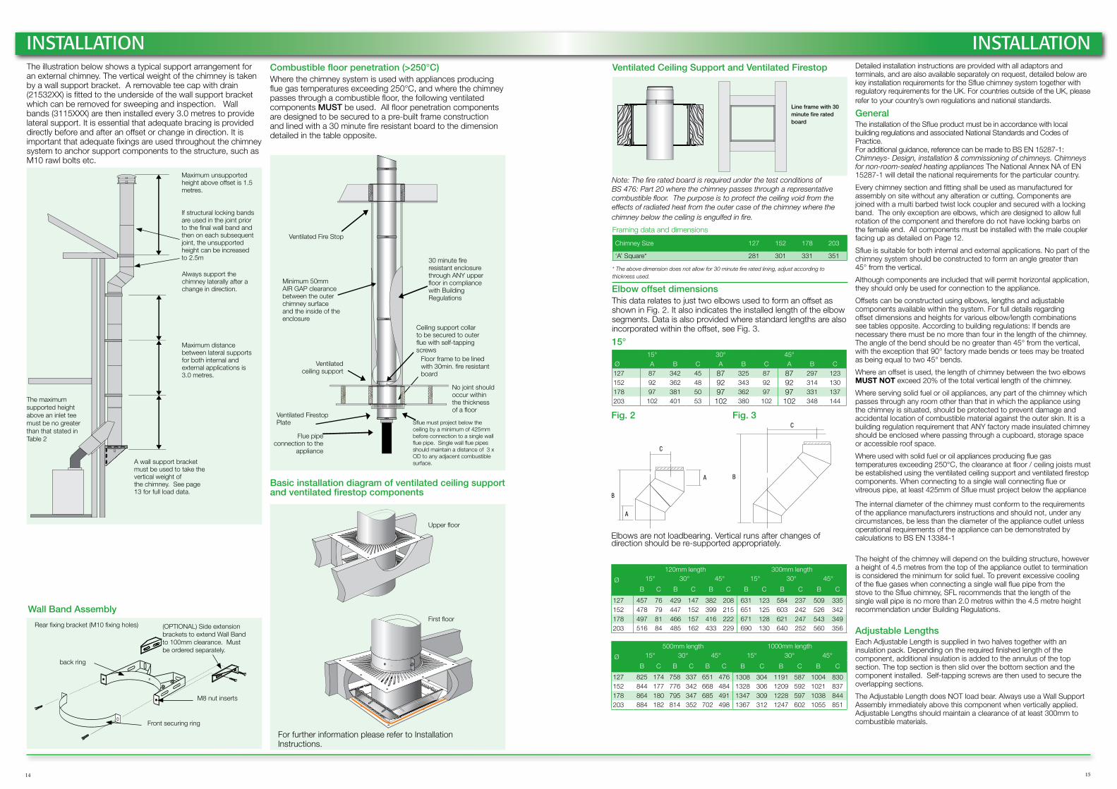
INSTALLATIONVentilated Ceiling Support and Ventilated Firestop
Framing data and dimensions
Chimney Size 127 152 178 203
‘A’ Square* 281 301 331 351
* The above dimension does not allow for 30 minute fire rated lining, adjust according to thickness used.
Line frame with 30 minute fire rated board
Note: The fire rated board is required under the test conditions of BS 476: Part 20 where the chimney passes through a representative combustible floor. The purpose is to protect the ceiling void from the effects of radiated heat from the outer case of the chimney where the chimney below the ceiling is engulfed in fire.
Detailed installation instructions are provided with all adaptors and terminals, and are also available separately on request, detailed below are key installation requirements for the Sflue chimney system together with regulatory requirements for the UK. For countries outside of the UK, please refer to your country’s own regulations and national standards.
GeneralThe installation of the Sflue product must be in accordance with local building regulations and associated National Standards and Codes of Practice. For additional guidance, reference can be made to BS EN 15287-1: Chimneys- Design, installation & commissioning of chimneys. Chimneys for non-room-sealed heating appliances The National Annex NA of EN 15287-1 will detail the national requirements for the particular country.
Every chimney section and fitting shall be used as manufactured for assembly on site without any alteration or cutting. Components are joined with a multi barbed twist lock coupler and secured with a locking band. The only exception are elbows, which are designed to allow full rotation of the component and therefore do not have locking barbs on the female end. All components must be installed with the male coupler facing up as detailed on Page 12.
Sflue is suitable for both internal and external applications. No part of the chimney system should be constructed to form an angle greater than 45° from the vertical.
Although components are included that will permit horizontal application, they should only be used for connection to the appliance.
Offsets can be constructed using elbows, lengths and adjustable components available within the system. For full details regarding offset dimensions and heights for various elbow/length combinations see tables opposite. According to building regulations: If bends are necessary there must be no more than four in the length of the chimney. The angle of the bend should be no greater than 45° from the vertical, with the exception that 90° factory made bends or tees may be treated as being equal to two 45° bends.
Where an offset is used, the length of chimney between the two elbows MUST NOT exceed 20% of the total vertical length of the chimney.
Where serving solid fuel or oil appliances, any part of the chimney which passes through any room other than that in which the appliance using the chimney is situated, should be protected to prevent damage and accidental location of combustible material against the outer skin. It is a building regulation requirement that ANY factory made insulated chimney should be enclosed where passing through a cupboard, storage space or accessible roof space.
Where used with solid fuel or oil appliances producing flue gas temperatures exceeding 250°C, the clearance at floor / ceiling joists must be established using the ventilated ceiling support and ventilated firestop components. When connecting to a single wall connecting flue or vitreous pipe, at least 425mm of Sflue must project below the appliance
The internal diameter of the chimney must conform to the requirements of the appliance manufacturers instructions and should not, under any circumstances, be less than the diameter of the appliance outlet unless operational requirements of the appliance can be demonstrated by calculations to BS EN 13384-1
The height of the chimney will depend on the building structure, however a height of 4.5 metres from the top of the appliance outlet to termination is considered the minimum for solid fuel. To prevent excessive cooling of the flue gases when connecting a single wall flue pipe from the stove to the Sflue chimney, SFL recommends that the length of the single wall pipe is no more than 2.0 metres within the 4.5 metre height recommendation under Building Regulations.
Adjustable LengthsEach Adjustable Length is supplied in two halves together with an insulation pack. Depending on the required finished length of the component, additional insulation is added to the annulus of the top section. The top section is then slid over the bottom section and the component installed. Self-tapping screws are then used to secure the overlapping sections.
The Adjustable Length does NOT load bear. Always use a Wall Support Assembly immediately above this component when vertically applied. Adjustable Lengths should maintain a clearance of at least 300mm to combustible materials.

UK Sales and Customer & Export Services
SF LtdPottington Business ParkBarnstapleDevon EX31 1LZTel: 01271 326633Fax: 01271 334303 [email protected]
In order to minimise the environmental impact on this publication, it has been printed locally, using vegetable based inks on FSC
® certified paper.
The information contained in this brochure was accurate at the date of publishing. However the company reserves the right to introduce at any time modifications and changes of details as may be necessary. To avoid any misunderstanding, interested parties should contact the company to confirm whether any material alterations have been made since the date of this brochure.
Sflu
e Li
tera
ture
© S
F Lt
d -
Vers
ion
0709
15
www.sflchimneys.com
Consider your environment and download the latest electronic version of the Sflue sales literature direct
from our website using the QR code
Single wall connecting flue pipe for multi fuel appliances
Smooth Joint SystemFully Welded
Available in Satin Black Finish
Diameters: 130mm-200mm
Twin & single wall multi fuel flexible liner
Triple Lock SeamHigh Strength
High TemperatureTwin Wall Construction
Diameters: 100mm-200mm
EN1856-2 T600 N1 D Vm L50020 GEN1856-2 T200 P2 W Vm L50020 O
EN1856-2 T600 N1 D V2 L50060 G(XX*) NMEN1856-2 T600 N1 D V2 L50060 G(400) M
*XX = 3xDiameter
SflueTOVE