stormwater management & drainage design 5.0 general
TRANSCRIPT

CCHHAAPPTTEERR 55
STORMWATER MANAGEMENT & DRAINAGE DESIGN 5.0 GENERAL
A. Drainage, for both water quantity and quality, shall be designed in general by the criteria established herein, the City's Master Drainage Plan, the Virginia Department of Transportation Drainage Manual and the Virginia Stormwater Management Handbook.
B. When there is a conflict between the Virginia Department of Transportation Drainage
Manual, the Hampton Roads Planning District Commission Regional Construction Standards and these criteria, these criteria shall govern.
C. Drainage calculations shall be accompanied by a drainage summary (i.e. narrative
describing existing and proposed drainage patterns, methods of analysis, assumptions, conclusions, etc.), drainage area maps including all offsite area and an explanation of all computer printouts and program methodology. The drainage calculations and narrative must ensure Adequate Drainage is provided with any proposed development.
D. All offsite public drainage easements shall be obtained prior to plan approval. E. All proposed public storm drain systems shall tie to an existing City maintained
public system or one constructed, bonded and pending acceptance. F. If a proposed development drains to a facility that is owned or maintained by another
local or state agency, then that agency's approval is required prior to plan approval. Approval shall be coordinated through the Department of Development & Permits.
G. Fill may not be placed in a flood plain below the 50 yr. design year storm elevation
without a construction plan which compensates the flood plain for any loss of natural detention volume or hydraulic capacity.
5.1 ADEQUATE DRAINAGE
A. Adequate drainage must have the hydraulic characteristics to accommodate increases in volume, velocity and peak flow rate of stormwater for the watershed or portion thereof, for the required design year storm or design year event.
Revised 7/13 STORMWATER MANAGEMENT & DRAINAGE DESIGN Page 5- 1

B. An Adequate Natural Outfall shall be as designated on the master drainage
topographic maps and is defined as having sufficient capacity to receive the ultimate runoff from the watershed without deterioration of the facility and without adversely affecting property in the watershed. The hydraulic grade line effect must be considered at the receiving facility.
C. A Designated Adequate Outfall shall be defined as a river, creek, or other drainage
facility so determined by the City for the proposed system. D. Adequate drainage is to be designed to:
1. Account for both offsite and onsite stormwaters, at ultimate development based on approved LAND USE PLAN prepared by the Chesapeake Planning Department;
2. Honor natural drainage divides (consideration of exceptions may be given
based on actual topographic survey & adequacy of outfall. 3. Convey stormwater to an adequate natural outfall or designated adequate
outfall. 4. Not adversely affect the adjacent or neighboring properties.
E. It is the responsibility of the developer to provide adequate drainage for the proposed development and the upstream watershed along or through his property at ultimate development. This includes accommodating the ultimate runoff at an acceptable hydraulic grade line consistent with upstream land elevations.
F. It is also the responsibility of the developer to provide adequate drainage to the
adequate natural outfall or the designated adequate outfall. Offsite facilities must be designed for increased volume and peak flow rates, which accommodate the current development offsite and ultimate development onsite. Staged construction will be considered for perimeter and offsite improvements where the developer's engineer can show that it is feasible. (70-123)
G. Additional studies and a higher level of design calculations may be required by the
City to assure adequate drainage in order to protect life and property.
H. Offsite drainage improvements will be required to prevent the proposed development from having any significant detrimental effect on the downstream facilities to an adequate natural outfall. Payment of pro rata drainage fees does not relieve the developer of making necessary off site drainage improvements.
I. Detention systems may still require offsite improvements to mitigate the impact of
increasing the volume of runoff or duration into an inadequate outfall. No offsite drainage improvements or easements shall be required when ALL of the following conditions are met:
Revised 7/13 STORMWATER MANAGEMENT & DRAINAGE DESIGN Page 5- 2
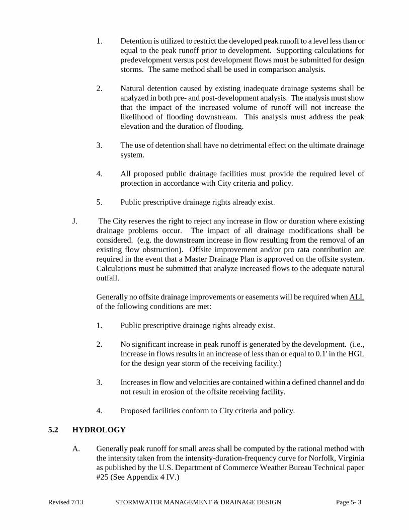
1. Detention is utilized to restrict the developed peak runoff to a level less than or equal to the peak runoff prior to development. Supporting calculations for predevelopment versus post development flows must be submitted for design storms. The same method shall be used in comparison analysis.
2. Natural detention caused by existing inadequate drainage systems shall be
analyzed in both pre- and post-development analysis. The analysis must show that the impact of the increased volume of runoff will not increase the likelihood of flooding downstream. This analysis must address the peak elevation and the duration of flooding.
3. The use of detention shall have no detrimental effect on the ultimate drainage
system. 4. All proposed public drainage facilities must provide the required level of
protection in accordance with City criteria and policy.
5. Public prescriptive drainage rights already exist.
J. The City reserves the right to reject any increase in flow or duration where existing drainage problems occur. The impact of all drainage modifications shall be considered. (e.g. the downstream increase in flow resulting from the removal of an existing flow obstruction). Offsite improvement and/or pro rata contribution are required in the event that a Master Drainage Plan is approved on the offsite system. Calculations must be submitted that analyze increased flows to the adequate natural outfall.
Generally no offsite drainage improvements or easements will be required when ALL of the following conditions are met:
1. Public prescriptive drainage rights already exist.
2. No significant increase in peak runoff is generated by the development. (i.e.,
Increase in flows results in an increase of less than or equal to 0.1' in the HGL for the design year storm of the receiving facility.)
3. Increases in flow and velocities are contained within a defined channel and do
not result in erosion of the offsite receiving facility.
4. Proposed facilities conform to City criteria and policy.
5.2 HYDROLOGY
A. Generally peak runoff for small areas shall be computed by the rational method with the intensity taken from the intensity-duration-frequency curve for Norfolk, Virginia as published by the U.S. Department of Commerce Weather Bureau Technical paper #25 (See Appendix 4 IV.)
Revised 7/13 STORMWATER MANAGEMENT & DRAINAGE DESIGN Page 5- 3

B. Where the drainage basin exceeds 200 acres or when a detention design is involved, hydrographic or other approved methods are to be used for design purposes. Hydrographs shall be based on a Soil Conservation Service (SCS) Type II, 24-hour duration storm. Total rainfall depths are listed in the following table:
24 Hour Rainfall Depths (NOAA’s NWS)
Total Design Rainfall Storm Depth
2-yr. 3.4" 5-yr. 5.0" 10-yr. 6.0” 25-yr. 7.0” 50-yr. 8.0" 100 9.0”
C. Acceptable methods for runoff analysis are tabulated below:
Method Drainage Area Rational Method 0 - 200 Acres (private sites/facilities only) TR-55 All TR-20 All HEC-HMS All SWMM ALL
Other methods subject to approval by City.
D. Runoff coefficients (C) and curve numbers (CN) shall be based on a weighted
coefficient or curve number for the composite area. The base values for calculating the weighted coefficient and curve number shall be: C CN* Paved and Roof Areas = 0.90 98 Lawns up to 2% Slope = 0.20 74 Wetlands = 0.15 73 Typical weighted coefficients and curve numbers are:
C CN* Farmettes (3) acre = 0.30 76 Residential 1/2 acre or more = 0.35 80 Residential 10,000 sq. ft. or more = 0.40 81 Residential less than 10,000 sq. ft. = 0.45 83 Apartments and Townhouses = 0.70 90 Parks, Lawns, etc. = 0.20 74 Woodlands = 0.10 70
** Industrial and Commercial = 0.75 min 94 Unimproved/Cultivated Land = 0.25 75
*** Gravel Parking Lots = 0.90 98
Revised 7/13 STORMWATER MANAGEMENT & DRAINAGE DESIGN Page 5- 4
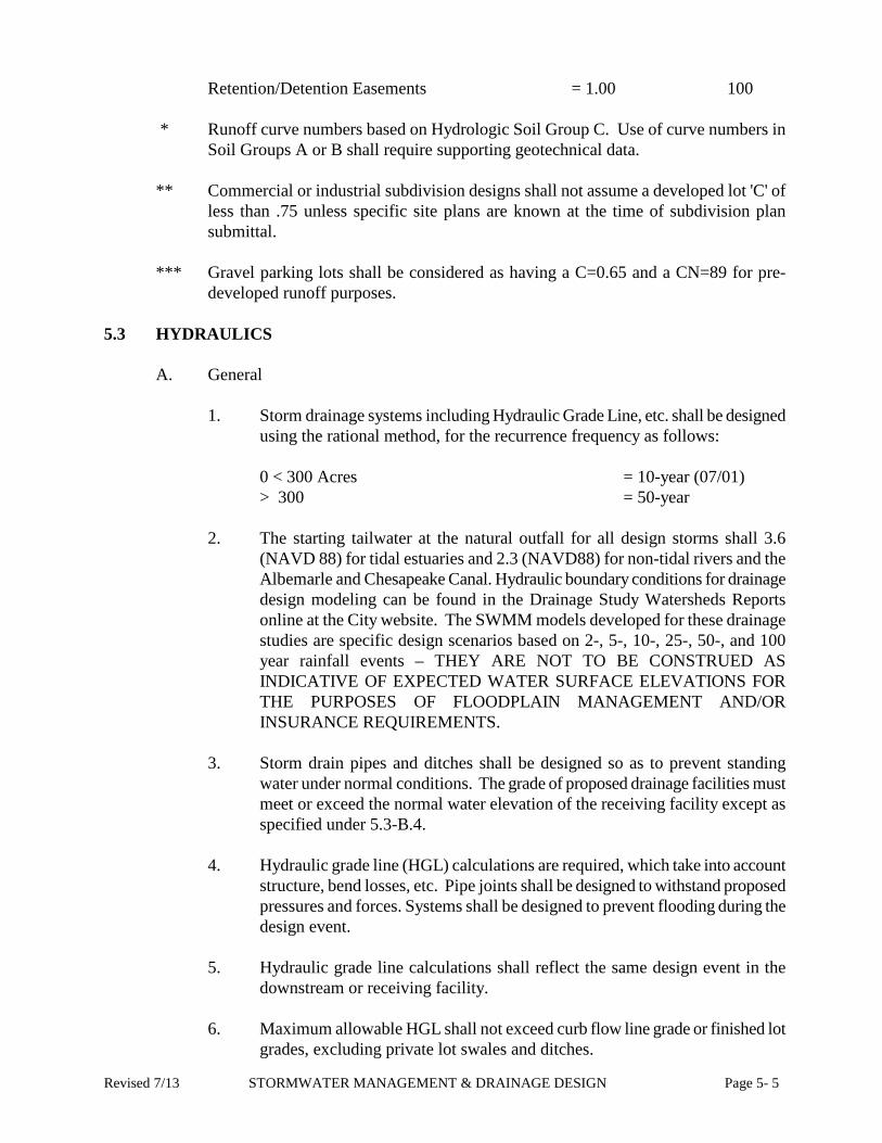
Retention/Detention Easements = 1.00 100 * Runoff curve numbers based on Hydrologic Soil Group C. Use of curve numbers in
Soil Groups A or B shall require supporting geotechnical data. ** Commercial or industrial subdivision designs shall not assume a developed lot 'C' of
less than .75 unless specific site plans are known at the time of subdivision plan submittal.
*** Gravel parking lots shall be considered as having a C=0.65 and a CN=89 for pre-
developed runoff purposes. 5.3 HYDRAULICS
A. General
1. Storm drainage systems including Hydraulic Grade Line, etc. shall be designed using the rational method, for the recurrence frequency as follows:
0 < 300 Acres = 10-year (07/01) > 300 = 50-year
2. The starting tailwater at the natural outfall for all design storms shall 3.6
(NAVD 88) for tidal estuaries and 2.3 (NAVD88) for non-tidal rivers and the Albemarle and Chesapeake Canal. Hydraulic boundary conditions for drainage design modeling can be found in the Drainage Study Watersheds Reports online at the City website. The SWMM models developed for these drainage studies are specific design scenarios based on 2-, 5-, 10-, 25-, 50-, and 100 year rainfall events – THEY ARE NOT TO BE CONSTRUED AS INDICATIVE OF EXPECTED WATER SURFACE ELEVATIONS FOR THE PURPOSES OF FLOODPLAIN MANAGEMENT AND/OR INSURANCE REQUIREMENTS.
3. Storm drain pipes and ditches shall be designed so as to prevent standing
water under normal conditions. The grade of proposed drainage facilities must meet or exceed the normal water elevation of the receiving facility except as specified under 5.3-B.4.
4. Hydraulic grade line (HGL) calculations are required, which take into account structure, bend losses, etc. Pipe joints shall be designed to withstand proposed pressures and forces. Systems shall be designed to prevent flooding during the design event.
5. Hydraulic grade line calculations shall reflect the same design event in the
downstream or receiving facility. 6. Maximum allowable HGL shall not exceed curb flow line grade or finished lot
grades, excluding private lot swales and ditches.
Revised 7/13 STORMWATER MANAGEMENT & DRAINAGE DESIGN Page 5- 5

7. Standard Manning Coefficients
Roughness coefficient for storm drain facilities shall be as defined in Table 2.8.2 of the VDOT Drainage Manual, except that 0.013 shall be used for concrete pipe and .011 for PVC and P.E. Existing and proposed earthen channels shall use a coefficient consistent with the anticipated conditions based on the City’s maintenance intervals as follows: (07/01)
Roadside Ditch - = .035 Lead Ditches - = .060
Canals/Channels - = .075 (07/01)
8. Adjacent properties cannot sheet flow across a proposed development. A collection system with drainage easement must be provided to drain any offsite flow.
B. Storm Drains & Culverts
1. Proposed storm drain systems shall not cause flooding during the design event.
2. The minimum pipe size shall be 15” if the pipe will be part of the Public Drainage System. Smaller diameter pipe may be considered when special circumstances exist, such as insufficient cover or clearance.
3. Materials:
a. Concrete
Class III R.C.P. required for all pipes in the right-of-way and those routinely subject to vehicular traffic including cross pipes in ditch maintenance strips. Since the service life of concrete pipe historically exceeds 50 years, no service life calculations will be required.
Higher class pipe shall be required in railroad crossings and excessive fill as defined by VDOT. (Class V or in accordance with railroad requirements).
b. HDPE (High-Density PolyEthylene)
The following conditions shall apply when HDPE pipe is pre-approved by the City for use in public easements. When manufacturer, Virginia Department of Transportation and City Specifications conflict; the most stringent shall govern. If HDPE storm drainage pipe is to be used in the right-of-way or in areas subject to traffic loading it must be installed in accordance with manufacturer's recommendations to support an HS-20 live load with a maximum deflection of 5% of the minimum pipe diameter specified in ASTM D3034. When allowed
Revised 7/13 STORMWATER MANAGEMENT & DRAINAGE DESIGN Page 5- 6

within public easements additional restraints are required or cal-culations must be submitted to show that there is sufficient restraint through adequate cover or other manufacturer approved methods to prevent floatation if cover is less than 1.5 times the pipe diameter. HDPE pipe shall not be approved as lake in-fall or outfall pipes.
In locations where less than 3 feet of cover is available, design and construction shall include the following:
i.) Virginia Department of Transportation type 57, angular stone
must be used for bedding, haunching and backfill. ii.) A minimum proctor density of 95% must be obtained. The
City reserves the right to call in an independent qualified testing firm to confirm proper proctor density.
iii.) Minimum cover may not be less than specified by the
manufacturer with 1' as the absolute minimum. iv.) Cover shall be measured from the top of the pipe to the mini-
mum finished grade elevation for rigid pavement and to the bottom of the pavement section for flexible pavement.
Construction plans must contain all necessary details and specifications for proper installation of HDPE storm drainage pipe. These shall include:
• Installation requirements • Backfill material specifications • Minimum proctor density requirements
4. Submerged storm drain systems are not acceptable. Lake entrance pipes may be submerged for erosion control purposes but shall not contain any standing water for more than 100' of their length or to a distance of one lot if system is piped between two residential lots. Typically, lake inflow pipes shall be set at normal water elevation. Lake outfall pipes shall be dry under normal conditions. A waiver for use of submerged pipes may be considered where pipe submergence is unavoidable.
5. The maximum length between access openings on a closed conduit system
shall not exceed 300’. 6. Prefabricated tee, wye or bend sections may be used only under extenuating
circumstances, when approved by the City. 7. There may not be a reduction in pipe size greater than one increment along the
direction of flow. 8. Changes in pipe size or material may only occur at structures.
Revised 7/13 STORMWATER MANAGEMENT & DRAINAGE DESIGN Page 5- 7

9. Radial storm drain pipes are not acceptable unless otherwise approved by the
City. If approved, the minimum radius must be in accordance with current VDOT requirements.
10. The length of pipe at a crossing is determined by ensuring a 2:1 side slope
exists from the top of the bank to the pipe invert. End treatments (flared end sections wing walls) are required for storm drain systems, per VDOT Drainage Manual.
11. Any development without curb and gutter must provide entrance/driveway
culverts for each lot. Minimum length is 24’. 12. Flows used in determining inlet and gutter capacities shall be derived using the
actual time of concentration at each point of analysis for a 10 year storm event. As an alternative a rainfall intensity of 4.0in./hr. may be used in lieu of submitting actual time of concentration calculations. Inlets shall be spaced and sized to eliminate pavement spreads in excess of 10' on the typical street section. Calculations are required with plan submittal.
13. Precast drainage structures may be substituted for City Standard drainage
structures provided that the contractor submits (prior to construction) a letter of certification from a registered Professional Engineer. This letter of certification must state that the precast structure(s) shop drawings have been reviewed, are structurally sound for HS-20 loading and will provide a 50 year service life. Certification is not required if VDOT Standard Structures are used.
14. Generally, the use of conflict manholes shall not be permitted. A waiver may
be granted by the City to approve the use of a conflict manhole in “hardship” cases. Drainage analysis must be submitted showing that the pipe system at this location is adequate for the appropriate design storm.
15. Storm drain facilities shall be designed to provide a 10-year design velocity of
not less than 2.5 ft./sec. Calculations must reflect actual hydraulic conditions. Consideration will be given to minimum pipe size for small drainage areas.
16. Calculations deriving the initial Tc of a storm drainage system must be
submitted with the plans. No supporting calculations are required if an initial Tc of 10 minutes is assumed in a residential subdivision.
17. The inverts of all drainage structures shall be shaped in accordance with City
Standard IS-1, PFM Volume II.
18. Drop inlets must utilize a Dl-1 frame and cover. Grates with round bars are only acceptable for limited access roadways.
19. The minimum acceptable cover over an entrance pipe is 9”. However, the pipe
Revised 7/13 STORMWATER MANAGEMENT & DRAINAGE DESIGN Page 5- 8

crown may not extend up into the pavement section. Cover can be reduced to 7” for concrete entrances.
20. All entrance pipes shall be sized for ultimate upstream development
(supporting calculations must be submitted). 21. Storm drainage drop inlet structures are not permitted in the entrance.
Manholes that are in the entrance must be designed to withstand HS-20 loading.
22. Onsite drainage systems will be required for car wash facilities. No drainage
from the car wash operation shall drain through the entrance or over the curb. 23. Public water shall not sheet flow onto private property.
C. Ditches, Channels, & Swales
1. Calculations shall be provided showing that the conveyance of runoff from the required design year storm event will not top the banks of a proposed ditch or existing receiving channel.
2. Maximum permissible ditch side slopes are 2:1. Steeper slopes will require
soil tests to determine that conditions will retain steeper slopes, acceptable stabilization methods or, paved inverts.
3. Swales are defined as being no more than 18” deep (24” for private swales),
no steeper than 4:1 side slopes with a minimum grade of .5% and carrying no more than (3.5 cfs) during the 10 year design event. Minimum desirable swale depth shall be 7 inches.
4. Swales shall not be used to drain ditches. 5. Paved inverts where required for erosion protection or where sections K and L
are applicable shall be constructed as per Chesapeake Standards. The maximum acceptable side slopes for the remaining earthen portion is 4:1. Adequate weep holes are required to control groundwater. Weep hole spacing calculations must be submitted with the plan.
6. The use of swales draining across the sidewalk into the gutter is generally
unacceptable. In those cases where necessary, flow shall be limited to less than one (1) cfs. These flows must be included in gutter capacity.
7. The minimum paved ditch invert width shall be 2 feet, the maximum width
shall be 10 feet. Supporting structural design calculations will be required for wider paved inverts.
8. The minimum bottom width for an earthen public ditch is 2 feet.
Consideration will be given when limited right-of-way exists.
Revised 7/13 STORMWATER MANAGEMENT & DRAINAGE DESIGN Page 5- 9

9. At all times during construction drainage shall be maintained through a
development to accommodate upstream areas until new facilities are in place and operational.
10. Existing ditches that are not publicly maintained and are proposed as public
facilities shall be upgraded to meet all City criteria as to side-slopes, bottom width, vegetation and maintenance strips. Maintenance strips shall be cleared of trees and spoil piles that interfere with maintenance functions.
11. Any new offsite ditches must be piped. 12. Existing Roadside Ditches.
a. Existing roadside ditches along the frontage of a development must be
piped if greater than 3 feet deep as measured from the lower top of bank to the invert of the ditch (except where permitted in Chapter 8 & SDMP Developments).
b. Regrading of offsite roadside ditches greater than 3 feet deep will not require piping. Regrading should not deepen the ditch more than 6 inches unless otherwise approved by the City. Removal of sediment to previously established inverts is not considered regrading.
c. Existing offsite roadside ditches greater than 3 ft in depth shall be relocated and a shoulder established (see Chapter 8) if the ditch is deepened more than 6 inches from previously established inverts.
d. Under no circumstances shall cleaning, construction or regrading of a
roadside ditch reduce the width of the existing shoulder.
e. A typical cross-section is required showing all roadside ditch work. The cross-section shall show the existing ditch, right-of-way line, edge of pavement and proposed excavation.
13. If a utility line is proposed to be installed adjacent to or below an existing
ditch, then the plan shall clearly show the direction of flow and require ditch restoration to include cleaning and regrading to proposed grades as shown on the plan, including any driveway pipe replacements.
5.4 STORMWATER MANAGEMENT
A. Water Quantity
1. Detention shall be defined as the provision of an acceptable storage area for stormwater with the use of a permanent control structure providing a significant reduction in the peak discharge of stormwater.
2. Detention of stormwater is desirable in many cases to alleviate existing
Revised 7/13 STORMWATER MANAGEMENT & DRAINAGE DESIGN Page 5- 10

downstream drainage problems and to preclude the development of new problems. Detention is mandatory where the existing downstream drainage system is clearly inadequate and its expansion or improvement is either financially prohibitive or aesthetically unacceptable. In watersheds with inadequate existing downstream facilities, downstream improvements and/or prolonged detention may be necessary. However, in some areas of the watersheds, detention will cause increased peak flows to occur on the major outfall. The City reserves the right to prohibit detention of storm-water where the City determines that its use is not in the public interest.
3. Generally detention facilities must be designed to return to a water surface
elevation that will provide 90% of the design event storage capacity within 48 hours of the beginning of a 24 hour SCS 10-year storm.
4. All public detention systems shall be designed to withstand a 50 -year storm
without failure of the control structure or property damage. A 50-year impoundment easement shall be dedicated for all public detention systems.
5. An emergency drainage-way should be provided for all public impoundments. This emergency drainage way shall provide an over flow path for impounded waters that will not result in property damage during the 100-year storm if the design storm elevation is exceeded.
6. In the event that an emergency spillway is impractical the engineer must show
that no property damage will result from a 100-year storm event in lieu of providing an emergency spillway.
7. The lowest finished lot grade outside of the impoundment easement must be
greater than the 50-year water surface elevation, excluding private lot swales. 8. Inflow and discharge pipes should be located as far as possible from each
other to allow for maximum sediment settling. Also, the dual/combined inlet/outlet pipe system is not an acceptable system.
9. The inverts of pipes whose purpose is to interconnect lake systems shall be no
more than 4' below the normal water elevation. 10. The limits of impoundment and the design storm volume shall be shown on
the plan and impoundment easement plat. Lot lines shall be extended through public impoundments.
11. Detention facilities with outfall structures openings less than 0.7 sq. ft. shall
have trash racks or riser structures to prevent clogging. Trash racks may be required when conditions warrant its use.
12. Prior to the construction of detention facilities, plans containing the minimum
and maximum depths and drainage calculations shall be submitted and approved unless a use permit has been obtained in accordance with City Code 26-222.
Revised 7/13 STORMWATER MANAGEMENT & DRAINAGE DESIGN Page 5- 11

13. Stage/storage/discharge calculations shall be based on the volume available
above the outflow control device invert. Analysis must consider any tailwater impact and reverse flow conditions.
14. Borrow pits that will be used for detention shall meet all City criteria and
policy except for depth. 15. Parking lot drainage detention systems should ensure that the maximum
possible ponding depth will not result in vehicular or property damage. 16. Private BMP’s shall not be located in public easements. 17. Dry Detention Requirements:
a. Cross Slope: Bottom 1% minimum
Side 4:1 maximum
b. Longitudinal Slope: Paved Invert 0.2% minimum
Grass Invert 0.5% minimum
c. Paved Invert - Minimum depth 12", weep holes will be required on both sides at a maximum interval of 4' center to center, minimum bottom width. Weep hole calculations are required. Sufficient weep holes required to control groundwater. Refer to Volume II of the PFM for detail and placement or filter fabric and stone bedding.
d. Grass Invert - Will not be permitted unless ground water tests are
submitted which show that the projected seasonal high water table will be a minimum of 12" below proposed flow line. Seasonal water table shall be projected based on water table observation at time of test (extreme weather conditions must be considered) and adjusted for the time of year, soil gradation and topography.
e. Restriction Plate - Use as an outflow control device is generally
unacceptable unless approved by the City. Where approved they must be welded in place.
18. Wet Detention Requirements:
a. Cross Slope (from top of bank to lake bottom) Residential Areas - 4:1 maximum Commercial/Industrial Areas - 3:1 maximum
b. Minimum normal water depth for public facilities shall be 8 feet. The
maximum depth of the facility shall be 20 feet as measured from the
Revised 7/13 STORMWATER MANAGEMENT & DRAINAGE DESIGN Page 5- 12

bottom of the excavation to the top of the bank. At no time shall an impoundment exceed 20 acres in area without a use permit (City Code 26-221(3))
c. Minimum desirable normal water width for public facilities is 100'.
Absolute minimum acceptable width is 80' where a result of a physical site restriction. (e.g. Virginia Power Tower). Reduction in the 80’ minimum will be considered when physical site restrictions dictate.
d. Calculations and tests shall show that the seasonal low water table will
support the normal water elevations proposed. Seasonal water table shall be projected based on water table observation at time of test and adjusted for the time of year, soil gradation and topography (extreme weather conditions must be considered.)
B. Water Quality
The following section applies to proposed developments and redevelopments Citywide for implementation of Best Management Practices (BMPs) for water quality. The policy and criteria apply City-wide and to all proposed developments and redevelopments in a Resource Protection Area (RPA) or Resource Management Area (RMA) as shown on the Chesapeake Bay Preservation Area Overlay District Map. This section is to be used to ensure compliance with the Chesapeake Bay Preservation Area Designation and Management Regulations as noted in Chapter 20 (section 9VAC10-20-110 thru 9VAC10-20-150) of the Virginia Administrative Code and the City’s Stormwater Management Ordinance, Chapter 26 - Article X of the City of Chesapeake Code. MASTER PLANNED AREAS Designers are advised that some areas of the City that were master planned with respect to water quantity and quality issues may be eligible for a variance to the Stormwater Management Ordinance since these areas do already provide the intended water quality protection mandated under the ordinance. BMPs may still be required, however, if the proposed site design exceeds the stormwater quantity that was originally anticipated. 1. Design Criteria
a. All criteria/policy shall be in accordance with Volume I of the Public Facilities
Manual. The following criteria is for any development or redevelopment, outside of RPA & RMA’s, which exceeds 10,000 square feet of land disturbance; within the RMA which exceed 2500 SF of land disturbance, or any land disturbance in the RPA.
b. The purpose and intent of these requirements are to prevent a net increase in
nonpoint source pollution Citywide from new development (i.e. the post development nonpoint source pollution runoff load can not exceed the predevelopment load based on average land cover conditions) and achieve a
Revised 7/13 STORMWATER MANAGEMENT & DRAINAGE DESIGN Page 5- 13

10% reduction in nonpoint source pollution for redevelopment within the CBPA (i.e. the post development nonpoint source pollution runoff must be 90% or less of the predevelopment load for a site in the CBPA). (Chesapeake Bay Preservation Area Designation and Management Regulations Section 9VAC10-20-110-A)
c. For land development where the existing percent impervious cover is greater
than the average land cover condition the pollutant discharge after development shall not exceed (i) the pollutant discharge based on existing condition less 10% or (ii) the pollutant discharge based on the average land cover condition, whichever is greater. (Virginia Stormwater Management Regulations Section 4VAC 3-20-71.B.3)
d. In order to meet the purpose and intent of this policy, designers will be
allowed to use one of the two following methods of achieving water quality: i.) Performance Based Method – designers shall use the worksheets from
DCR’s Stormwater Management Handbook. ii.) Technology Based Method – designers shall use the worksheets
provided later in this section.
The designer is directed to refer to Department of Conservation and Recreation’s (DCR) 1999 Stormwater Management Handbook for more details on the two methods and to the flow chart provided on page to help in choosing which method to apply given a known development situation.
e. Major subdivisions shall not have BMP's for individual lots. Centrally located
BMP's shall be utilized. f. The predevelopment non-point source pollution runoff load shall be based on
average land cover conditions, and the associated % imperviousness shown in the “Equivalent Impervious Cover for Watershed Table” of this policy.
Table 1: Equivalent Impervious Cover for Watershed (I watershed)
Equivalent Impervious Cover for Watershed Watershed Percentage (%) Albermarle and Chesapeake CD-1, CD-2, & CD-3 HR-1
16 29 29
Eastern Branch of the Elizabeth River 52 North Landing River 16 Northwest River 16 Southern Branch of the Elizabeth River BM-2 & BM-3
28 28
Revised 7/13 STORMWATER MANAGEMENT & DRAINAGE DESIGN Page 5- 14

Western Branch of the Elizabeth River 26 Note: Above equivalent impervious values shall be used regardless of the the method of calculation (Performance Based or Technology Based)
g. The limits of the RPA, RMA and floodplains shall be delineated on all final plans and plats (Chesapeake Bay Preservation Area Designation and Management Regulations Section 9VAC10-20-191.A.4). The Chesapeake Bay Preservation Area Overlay District Map is located in the Chesapeake Planning Department. The Watershed Overlay map is located in the Chesapeake Development & Permits Department.
2. General Construction Requirements
a. Vegetation shall be established where required in accordance with the
Virginia Erosion and Sediment Control Handbook or as approved by the City.
b. Control structures shall be in accordance with PFM Volume II or
VDOT specs as applicable, unless otherwise approved by the City. Any other structure must be certified by a P.E. for HS20 loading.
c. Riser structures shall have a minimum diameter 3” holes and suitable
methods to prevent clogging. d. Trash racks are required when outlet openings are less than .7ft² to
prevent clogging from floating debris. The top of the trash rack shall be on the same elevation as the design high water elevation.
e. Prior to initiation of any land disturbing activity exceeding 10,000
square feet in area (2,500 square feet in CBPA areas), all necessary permits required by federal, state and local regulations shall be obtained and evidence of such submitted to the Department of Development & Permits. If no permits are required it shall be noted on the plan.
f. Erosion and sediment control plans are required for land disturbance greater than 10,000 square feet outside the CBPA or 2,500 square feet in CBPA areas. The limits of land disturbance, including clearing and grading shall be clearly shown on the plans and physically marked on the development site.
3. Maintenance and Inspection Requirements
a. Maintenance of private best management practices shall be the
responsibility of the property owner.
Revised 7/13 STORMWATER MANAGEMENT & DRAINAGE DESIGN Page 5- 15

b. Maintenance agreements for residential and non-residential site plans shall be executed prior to construction plan approval. Maintenance agreements for subdivisions shall be executed prior to or concurrently with plat recordation. City standard agreements shall be used.
Revised 7/13 STORMWATER MANAGEMENT & DRAINAGE DESIGN Page 5- 16

4. Acceptable BMP Facilities: TABLE 2
APPROVED BMP’S AND THE COMPARITIVE POLLUTANT REMOVAL EFFICIENCY
Water Quality BMP Virginia Stormwater Management Handbook Min. Std.
Target Phosphorus
Removal Efficiency
Percent Impervious
Cover
Vegetated Filter Strip 3.14 - min. 25' long, drainage area < 5ac. 10% 16-21% Grass Swale 3.13 - low gradient swale w/ check dams 15% Stormceptor (manufactured BMP)
3.15A - design per manufacturer recommend. to achieve stated removal rate 15-20%
Constructed Wetlands 3.09 - 2 x WQV 30% 22-37% Extended Detention 3.07 - 30 hr drawdown of 2 x WQV 35% Water Quality Swale 3.13 - ref. DCR's SWM Handbook for details 35% Retention Basin I 3.06 - permanent pool volume = 3 x WQV 40%
Bioretention Basin 3.11 - treat. vol. = 1/2" runoff from impervious areas 50% 38-66%
Bioretention Filter 3.11A - treat. vol. = 1/2" runoff from impervious areas 50%
Enhanced Extended Detention
3.07 - 30 hr drawdown of 1 x WQV, and 1 x WQV shallow marsh
50%
Retention Basin II 3.06 - permanent pool volume = 4 x WQV 50%
Infiltration 3.10 - storage vol. = 1/2" runoff from impervious areas 50%
Intermitten Sand Filter 3.12 - treating 1/2" runoff from impervious areas 65% 67-100%
Infiltration 3.10 - storage vol. = 1" runoff from impervious areas 65%
Retention Basin III 3.06 - permanent pool vol. = 4 x WQV, aquatic bench 65%
Bioretention Basin 3.11 - treat. vol. = 1" runoff from impervious areas 65%
Bioretention Filter 3.11A - treat vol. = 1" runoff from impervious areas 65%
Filterra (manufactured bioretention filter BMP)
3.11C - design per manufacturer recommendations
65%
Notes: • WQV = Water Quality Volume (first ½” of runoff from the impervious areas) • Refer to the Virginia Stormwater Management Handbook for design standards and specifications for the BMP’s listed above • The Keystone Pollutant designated for Virginia is total phosporus.
5. Design Calculations
Revised 7/13 STORMWATER MANAGEMENT & DRAINAGE DESIGN Page 5- 17
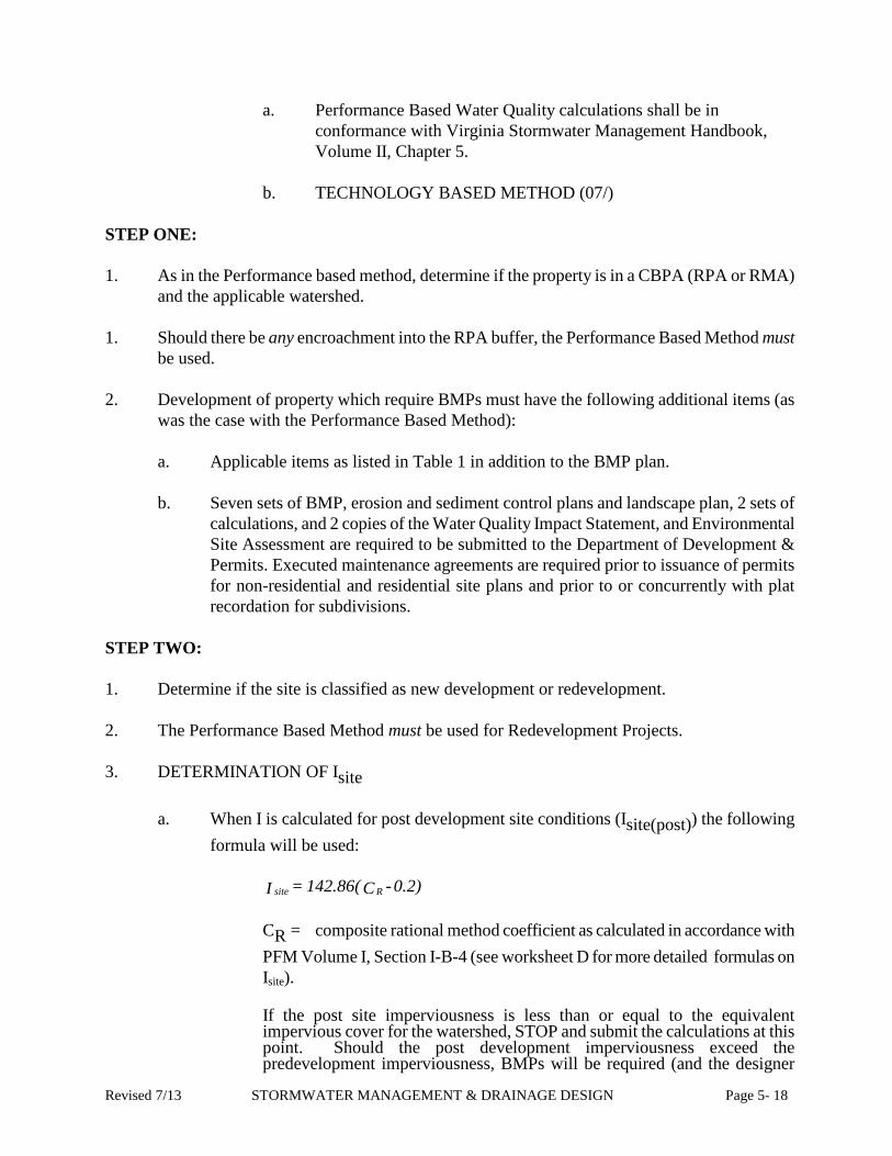
a. Performance Based Water Quality calculations shall be in
conformance with Virginia Stormwater Management Handbook, Volume II, Chapter 5.
b. TECHNOLOGY BASED METHOD (07/)
STEP ONE: 1. As in the Performance based method, determine if the property is in a CBPA (RPA or RMA)
and the applicable watershed. 1. Should there be any encroachment into the RPA buffer, the Performance Based Method must
be used. 2. Development of property which require BMPs must have the following additional items (as
was the case with the Performance Based Method):
a. Applicable items as listed in Table 1 in addition to the BMP plan. b. Seven sets of BMP, erosion and sediment control plans and landscape plan, 2 sets of
calculations, and 2 copies of the Water Quality Impact Statement, and Environmental Site Assessment are required to be submitted to the Department of Development & Permits. Executed maintenance agreements are required prior to issuance of permits for non-residential and residential site plans and prior to or concurrently with plat recordation for subdivisions.
STEP TWO: 1. Determine if the site is classified as new development or redevelopment. 2. The Performance Based Method must be used for Redevelopment Projects. 3. DETERMINATION OF Isite
a. When I is calculated for post development site conditions (Isite(post)) the following formula will be used:
0.2)-C142.86(=I Rsite
CR = composite rational method coefficient as calculated in accordance with PFM Volume I, Section I-B-4 (see worksheet D for more detailed formulas on Isite).
If the post site imperviousness is less than or equal to the equivalent impervious cover for the watershed, STOP and submit the calculations at this point. Should the post development imperviousness exceed the predevelopment imperviousness, BMPs will be required (and the designer
Revised 7/13 STORMWATER MANAGEMENT & DRAINAGE DESIGN Page 5- 18

needs to complete the remainder of the calculations).
STEP THREE: 1. Enter Table 2 with the post development site imperviousness from Step Two. Find the
appropriate Percent Impervious Cover range, and select a Water Quality BMP corresponding to that range.
STEP FOUR: 1. Determine the Area of the Site or the Planning Area to be used on the worksheet for Asite. In
most cases, Asite will be the area of the entire parcel. However, in cases where only a portion of the site is to be developed, the Planning Area shall be used for Asite. I.e., only the area to be developed and its perimeter buffers shall be considered as the Planning Area or Asite on the worksheet.
STEP FIVE: 1. Determine the Area draining to the Primary BMP(s). The Primary BMP(s) will be the
BMP(s) selected in Step 3 above. The area of the site that cannot practically drain to the Primary BMP(s) shall be designed to drain to a Secondary BMP(s) if at all possible.
STEP SIX: 1. A forebay area must be provided prior to a Primary BMP. It shall be sized in accordance with
the guidance listed in the information below:
~ 0.25 inch per impervious acre (recommended) ~ 0.10 inch per impervious acre (minimum) ~ For SWMFs treating only the first ½ inch of runoff, 10% of detention volume can be used for the forebay volume. ~ Forebays should be 4 to 6 feet deep.
STEP SEVEN: LANDSCAPING REQUIREMENTS 1. Provide required landscaping within and around the BMP areas. This Landscaping shall be
known as a “G” buffer. Following is some guidance on placement of G-buffer landscaping: a. Designer shall place landscaping around BMP as much as practicable, using
“clustering” of landscaping whenever possible. b. In no case shall the landscaping be placed more than 50 feet away from a Primary
BMP and 15 feet from Secondary BMP(s).
Revised 7/13 STORMWATER MANAGEMENT & DRAINAGE DESIGN Page 5- 19

2. Landscaping shall be required as follows:
Buffer Yard Width of Buffer Plants Required Per 100 Linear
Feet of Buffer Width G-1 (Principal BMPs) 20’ recommended
(10’ minimum) 5 large trees, 20 shrubs 30-36” height
G-2 (Secondary BMPs) 10’ shrubs 30-36”
i. When trees are permitted within BMPs they shall be water tolerant species, and shall
be approved by the City Arborist.
ii.When shrubs are permitted within BMPs they shall be of water tolerant species and shall be approved by the City Arborist.
Notes: i. Trees and shrubs are defined in Chesapeake Zoning Ordinance
19-600. ii. Landscaping provided for the G-buffer shall count towards the
canopy requirements for site and subdivision plans. iii. Landscaping provided for the G-Buffer shall count towards
required buffers so long as the BMPs are oriented to provide a continuous landscaping buffer as intended by the Landscaping Ordinance.
iv. In NO case shall the G-buffer negate the need for planter island tress.
Note: This method NOT to be used for Redevelopment Projects, Projects with Buffer
Encroachments.
Revised 7/13 STORMWATER MANAGEMENT & DRAINAGE DESIGN Page 5- 20

WORK SHEET D - Technology Method (07/01) 3. Compile POST-DEVELOPMENT site-specific data and determine site imperviousness (Isite).
Area in Acres
Rational Method CRA CRA
* A= CRA=
=A
CA=CR ∑∑ =
=0.2)-C142.86(=I Rsite (percent expressed in whole numbers)
*The area subject to regulations is the entire parcel area or the “Planning Area”. See definitions in this policy.
4. Determine the average land cover conditions (Iwatershed).
Use Iwatershed = _________% from Equivalent Impervious Cover for Watershed Table 5. Determine need to continue.
=I site % (from Step 1)
Iwatershed = % from applicable watershed (from Step 2)
If II watershedsite ≤ ,STOP and submit analysis to this point. If II watershedsite , CONTINUE.
6. To determine the appropriate Primary BMP(s) required, enter Table 3 with the Percent Impervious Cover for the site (or Planning Area) determined in Step 2 above.
Applicable Percent Impervious Cover Range = ____________ (from Table 3)
Primary BMP Design Proposed ________________
Revised 7/13 STORMWATER MANAGEMENT & DRAINAGE DESIGN Page 5- 21

7. Provide adequate coverage of site (or Planning Area) with BMPs:
a. Area of Site* = ________ = ASITE *The area subject to regulations is the entire parcel area or the “Planning Area”. See definitions in this policy.
b. Area of Site to Primary BMP(s) = ________ = A PRIMARY BMP c. Area of Site to Secondary BMPs = A SEC BMP = ________
d. Area of Site to All BMPs = A primary BMP + A SEC BMP = ___________ = A BMP
8. Provide forebay area to Primary BMP (see also Forbay Design Guidelines):
[Note: Forebay volume will count towards BMP volume, but only up to 10% of the total required volume] a. For BMP sized to treat 0.5 in/imp ac
VFOREBAY = 10% V BMP (where V BMP is the volume of the BMP based on 0.5 in/imp ac)
b. For BMP sized to treat > 0.5 in/imp ac
VFOREBAY = 0.25 in/imp ac (recommended) VFOREBAY = 0.10 in/imp ac (minimum)
9. Provide required landscaping as described in Step Seven of the Technology Based Method. Landscaping shall be required as follows:
Buffer Yard Width of Buffer Plants Required Per 100 Linear Feet of Buffer Width
G-1 (Principal BMPs) 20' recommended (10' minimum)
5 large trees, 20 shrubs 30-36" height
G-2 (Secondary BMPs) 10' 25 shrubs 30-36" height
Worksheet D facilitates calculation procedure for the Technology Based Method. The applicable worksheet must be completed and accompany plan submittals.
Revised 7/13 STORMWATER MANAGEMENT & DRAINAGE DESIGN Page 5- 22

EASEMENTS
A. Easement Widths:
1. Storm Drain Pipes - "Drainage Easement” shall be centered over pipe.
W = 2d + D + 2 (rounded up to nearest 5' within the development) Where d = Depth of pipe (Invert to F.G.) Where D = Diameter of pipe (I.D.) Where W = Easement width Minimum Width = 20’
2. Ditches - Easements for open drainage ditches must be delineated as a
combination easement ("Drainage/Access Easement"). The total width for the drainage facility and maintenance strip(s) shall be determined as indicated below. Additional easements may be necessary to access drainage facilities located in remote areas of a development.
PUBLIC DITCH EASEMENT GUIDELINE
Top of Bank Width (T) (FT)
Minimum Drainage Easement
(Total) (FT)
Minimum Width of
Maintenance Strip (FT)
Maintenance Strip on 1
side or Both Sides (FT)
T<10 25 (15) 1 10<T15 30 (15) 1 15<T<20 40 (20) 1 20<T<25 45 (20) 1 25<T<30 50 (20) 1 30<T<35 55 (20) 1 35<T<40 80 (20) 2 40<T<50 90 (20) 2
Plans must address the disposal of all spoil. Spoil deposition in maintenance strip is generally unacceptable. * All ditches with top of bank width of 50' or larger should have easement width approved by the City prior to plan submittal.
NOTE: Dedication of that portion of the ultimate easement which lies on the developers property shall be required for existing City maintained or public facilities through or adjacent to proposed development.
Revised 7/13 STORMWATER MANAGEMENT & DRAINAGE DESIGN Page 5- 23

B. All instruments recording easements must have verbiage from Appendix VII to
identify the purpose and restrictions of the easement. Alternative language may be considered on a case-by-case basis. Additional review time will be required to allow for the City Attorney’s Office to review and comment.
C. Public detention easements will require a note for each impoundment facility to appear on the plat in accordance with Appendix VII:
D. Private stormwater management facility easements shall be recorded on standard form
agreement provided by the City. (See Appendix XXIX).
E. Private drainage easements shall be required when lot drainage passes through adjacent lots (see Appendix X).
F. Developments adjacent to natural outfalls must dedicate drainage and/or impoundment easements to the 50 yr. design storm elevation contour.
G. Where detention facilities are used, the limits of impoundment must be shown on the plan by
metes and bounds. H. Detention Facilities
Detention facilities must be provided with a permanent "Lake Access," free of any obstacles
that could obstruct maintenance of the facility or access for public safety personnel. An acceptable "Lake Access" can be provided with one of the following methods: 1. Some portion of the lake perimeter must be immediately adjacent to a public
improved roadway, and provide a minimum 20 feet unobstructed width from such roadway to the lakes edge.
2. Where detention facilities are NOT immediately adjacent to a public improved
roadway a specifically designated 20' width minimum Lake Access Easement from a public roadway to the detention facility shall be provided with the following requirements:
a. CG-7 entrance 12' in width at the Lake Access Easement/public road intersection. Access easement shall be constructed of an all weather surface designed to support adequately emergency apparatus likely to be operated on the access easement in adverse conditions. The surface may be cosmetically appealing such as grass, as long as adequate subgrade support structure exists.
See PFM, Volume II, for standard detail.
b. The Lake Access Easement can co-exist with a drainage easement, but still
Revised 7/13 STORMWATER MANAGEMENT & DRAINAGE DESIGN Page 5- 24

must be designated specifically as a Lake Access Easement, on the construction plan and plat. The verbatim Lake Access Easement language from Appendix VII must be provided on the plat.
c. The Lake Access Easement should intersect the detention facility at the outfall structure, unless a variance is requested and granted otherwise. The easement should be configured whereas the outfall structure will not obstruct access to the lake's edge for emergency operations and equipment. A minimum 12-foot wide sloping access shall be provided to the water's edge for ease of emergency lake access by water apparatus and personnel.
I. Excess excavated material shall not be left in public easements. If it is to be taken off site, proper authorization is required and fees paid to the Commissioner of Revenue in accordance with City Code. (26-222-223). Spoil may be graded into low berms within maintenance strips as long as it does not interfere with drainage or access.
5.5 PIPE POLICY
A. Proposed drainage facilities shall be designed in a manner to minimize the construction of ditches that require City maintenance. To the greatest extent practical, public drainage systems will be piped and constructed within City right-of-way. The construction of new ditches and/or the alteration of existing drainage patterns, that in effect creates new public drainage ditches will not be permitted.
B. Pipe Policy in New Subdivisions (not including SDMP subdivisions):
1. All interior ditches shall be piped in their entirety. 2. A perimeter ditch is defined as a facility that generally follows a property boundary.
If the ultimate cross-section of the ultimate required easement extends to the property boundary, the existing ditch shall be considered a perimeter facility.
3. Perimeter ditches whose sole function is to drain the subject subdivision shall be
piped in their entirety.
4. Perimeter ditches which drain adjacent and upstream lands shall be piped in accordance with the following formula: "The subject subdivision shall install pipe in fifty percent of the linear distance of each common boundary between the subject subdivision and each adjacent undeveloped property. When the perimeter ditch divides the subject subdivision from an existing subdivision, the fifty-percent shall be applied to the common boundary of the two subdivisions. In calculating the length of pipe that shall be required, the measurements shall exclude any pipe to be placed under existing or proposed streets and highways. The location of the pipe to be installed shall be subject to the approval of the City. When the subject subdivision abuts an existing subdivision which has been developed under the requirements of this Pipe Policy, the subject subdivision shall install pipe in the remainder of the
Revised 7/13 STORMWATER MANAGEMENT & DRAINAGE DESIGN Page 5- 25

perimeter ditch to provide a one-hundred percent piped facility". (Council Adopted Policy)
5. Where perimeter ditches are ravine-like in nature (i.e. have no well-defined top of bank) or have existing sideslopes greater than 3:1 and are capable of passing the ultimate design flows, the perimeter ditch may be exempted from piping by the City. Brush removal, longitudinal regrading and bank sloping shall be required to maximize hydraulic performance.
6. Where approved by the City, a paved ditch may be used in lieu of perimeter or interior piping. The standard paved invert will be 2 feet deep and have 1:1 sideslopes. The maximum grass sideslope above the paving shall be 4:1. A one (1) foot wide invert with a .2% longitudinal slope shall be used for equivalent pipe sizes from 12" up to and including 36". The equivalent paved ditch for pipe sizes 42" to 60" shall have a 2' wide invert and a minimum slope of .1%. Ditches with paved inverts shall generally be less than 5' deep and shall contain the design storm below the top of bank.
7. In the event a perimeter ditch carries a quantity of runoff that exceeds the capacity of
an equivalent 60-inch pipe size as determined by the City, the perimeter ditch facility may be constructed as a paved ditch in lieu of pipe at the discretion of the developer. The determination of capacity will be based on hydrological and hydraulic criteria specified in this chapter. However, if the diversion of additional drainage areas to the perimeter ditch cause the ditch flows to exceed the capacity of a 60-inch pipe, then the facility must be piped regardless of the pipe size required.
8. Where perimeter ditches are permitted in subdivisions, stub streets or temporary cul-
de-sacs will be constructed to the ultimate top of bank. Right-of-way shall be dedi-cated to the property line and the perimeter ditch crossing must be designed. This crossing will be fully bonded over the normal subdivision bond period. If no adjacent development has required the extension of the street, prior to acceptance of subdivision by the City a two (2) year ancillary bond must be posted for one-half the improvement and will be accepted in lieu of actual installation. At the end of the 2-year ancillary bond period if no street extension is required, the ancillary bond will be released.
9. In some cases, the perimeter facility may require permitting from a Federal agency to
pipe or pave. If the Federal agency rejects the permit, evidence shall be provided of said rejection. An alternative equivalent facility shall be provided to the City for consideration. Any alternative must provide the appropriate hydraulic characteristics while minimizing future City maintenance responsibilities.
10. In situations where the adjacent property owner refuses to permit piping of the perimeter ditch, the 50% piping shall be done entirely on the developer's property so as to establish a parallel system with the existing ditch. The appropriate width easement must be dedicated in accordance with section 5.5 of this chapter.
Revised 7/13 STORMWATER MANAGEMENT & DRAINAGE DESIGN Page 5- 26
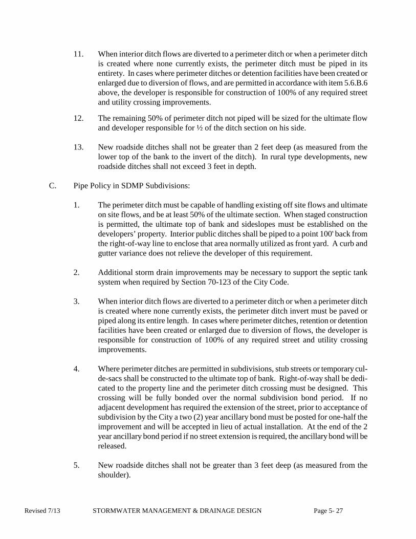
11. When interior ditch flows are diverted to a perimeter ditch or when a perimeter ditch is created where none currently exists, the perimeter ditch must be piped in its entirety. In cases where perimeter ditches or detention facilities have been created or enlarged due to diversion of flows, and are permitted in accordance with item 5.6.B.6 above, the developer is responsible for construction of 100% of any required street and utility crossing improvements.
12. The remaining 50% of perimeter ditch not piped will be sized for the ultimate flow and developer responsible for ½ of the ditch section on his side.
13. New roadside ditches shall not be greater than 2 feet deep (as measured from the
lower top of the bank to the invert of the ditch). In rural type developments, new roadside ditches shall not exceed 3 feet in depth.
C. Pipe Policy in SDMP Subdivisions:
1. The perimeter ditch must be capable of handling existing off site flows and ultimate
on site flows, and be at least 50% of the ultimate section. When staged construction is permitted, the ultimate top of bank and sideslopes must be established on the developers’ property. Interior public ditches shall be piped to a point 100' back from the right-of-way line to enclose that area normally utilized as front yard. A curb and gutter variance does not relieve the developer of this requirement.
2. Additional storm drain improvements may be necessary to support the septic tank
system when required by Section 70-123 of the City Code.
3. When interior ditch flows are diverted to a perimeter ditch or when a perimeter ditch is created where none currently exists, the perimeter ditch invert must be paved or piped along its entire length. In cases where perimeter ditches, retention or detention facilities have been created or enlarged due to diversion of flows, the developer is responsible for construction of 100% of any required street and utility crossing improvements.
4. Where perimeter ditches are permitted in subdivisions, stub streets or temporary cul-
de-sacs shall be constructed to the ultimate top of bank. Right-of-way shall be dedi-cated to the property line and the perimeter ditch crossing must be designed. This crossing will be fully bonded over the normal subdivision bond period. If no adjacent development has required the extension of the street, prior to acceptance of subdivision by the City a two (2) year ancillary bond must be posted for one-half the improvement and will be accepted in lieu of actual installation. At the end of the 2 year ancillary bond period if no street extension is required, the ancillary bond will be released.
5. New roadside ditches shall not be greater than 3 feet deep (as measured from the
shoulder).
Revised 7/13 STORMWATER MANAGEMENT & DRAINAGE DESIGN Page 5- 27

5.6 MASTER DRAINAGE AND DRAINAGE PRO-RATA
A Master Drainage Plan has been established in accordance with Section 70-123 City Code in order to ensure orderly development within the City. Developers are required to adhere to this plan. The Master Drainage Plan separates the City into drainage basins, sub-basins and sub-areas so as to define the drainage outfall and downstream improvements necessary for ultimate development in accordance with the approved LAND USE PLAN. Any drainage sub-basins that require improvements are assigned a pro rata drainage coefficient. A developer shall be required to contribute his share in cash and/or through pro rata improvements prior to final approval for site plans or plat recordation for subdivisions. Payment of pro rata does not relieve the developer of making all improvements necessary to provide adequate drainage as specified below. A pro rata improvement is a facility that has been specified in the Master Drainage Plan and generally serves an area of one-half square mile or more. However, a pro rata facility can be any facility required by the City Master Drainage Plan.
A. Definitions:
1. Pro Rata - The concept where by the cost and responsibility of developing a storm
drainage system capable of passing the design storm at ultimate development is shared by both the City and developers. The City accepts that portion of im-provements required by existing developments and areas to remain undeveloped and the developer is required to pay his share of the improvements based on the rate of runoff generated by his development.
2. Pro Rata Facility - Any improvement specified in the Master Drainage Plan where the
estimated cost was used in the determination of a Pro Rata Coefficient (PRC). A "Pro Rata Facility" generally consists of channel improvements, road crossings and drainage easements.
B. Plan Description:
1. A Pro Rata Coefficient (PRC) has been established for each of the areas studied in
the Master Drainage Plan. A developer’s pro rata share is a function of the master drainage improvements required for the watershed and the impervious area within the corresponding master drainage sub-basin or area. Pro rata coefficients are derived from the following formula:
PRC = CI CA
Where:
PRC = Pro Rata Coefficient CI = Total Cost of Improvements required by the adopted Master Plan for
the respective drainage sub-basin or area. C = Ultimate Composite Rational Coefficient anticipated under the
Revised 7/13 STORMWATER MANAGEMENT & DRAINAGE DESIGN Page 5- 28

approved future Land Use Plan. A = Total area of watershed in acres.
2. A developers pro rata share will be determined by the following formula:
$ = PRC x C x A x RF
Where: $ = Developers Pro Rata Share
PRC = Pro Rata Coefficient for Drainage Sub-basin.
C = Ultimate Composite Rational Coefficient for the Development. A = Total Acreage for Development. RF = Pro Rata reduction factor for detention (see Item 5.7.C.9 below).
3. In order to keep pro rata coefficients current with anticipated easement and
construction costs, annual updates will be performed. 4. Construction costs for each watershed may be recalculated to accurately reflect the
anticipated costs for programmed improvements. Construction cost revisions for inflation will be based on the Construction Cost Index published in the Market Trends section of the Engineering News Record. Easement costs will be based on the current land value established by the Chesapeake Real Estate Assessor's Office.
5. A pro rata coefficient will be given in the initial review letter. The developers pro
rata contribution will be based on this coefficient for a period of one year. If the plan has not been approved within one year of the initial review, the current pro rata coefficient will be used to determine the developers pro rata share of improvements. Subdivision sections recorded within 1 year of approval will use the pro rata coefficient given in the approval letter. After 1 year the unrecorded subdivision sections will be subject to the current pro rata coefficient for the watershed.
C. General Requirements:
1. The developer must participate in improvements proposed in the City Master Drainage Plan by either cash contributions or through City approved master drainage improvements.
2. The required monetary participation (cash or check) must be deposited prior to or concurrently with approval of the subdivision plat for recordation or prior to approval of plans for all other types of developments.
3. Participation is based on the current drainage pro rata fee schedule available from the Departments of Public Works or Development & Permits. This schedule is updated annually.
4. Pro rata concept is only applicable to watersheds included in the current Master
Revised 7/13 STORMWATER MANAGEMENT & DRAINAGE DESIGN Page 5- 29

Drainage Plan.
5. The developer is responsible for participation in pro rata if his development is located in any study area included in the Master Drainage Plan regardless of whether or not detention is used.
6. In addition to pro rata requirements the developer is responsible for providing those
improvements and easements necessary to provide adequate capacity to the existing offsite facilities between his site and a City designated "Pro Rata Facility".
7. In the event that the proposed development does not meet current criteria with its
offsite and/or pro rata improvements, the developer has the option of making additional "Pro Rata Facility" improvements or waiting for future improvements to be made by others prior to or concurrently with his development.
8. Credit for construction of Pro Rata Facilities or credit for easement dedication will be
based on the values used to determine the current Pro Rata Coefficient as determined by the City. Easement and construction costs are evaluated annually.
9. The developer may choose to use detention in his development within a watershed
where no detention is required by the Master Drainage Plan for that specific watershed. If the proposed detention system detains post-development discharge to less than or equal to pre- development flows for the design storm event, the following pro rata reduction factors will apply:
CHANGE IN FACTOR C (C)
% REDUCTION
PRO RATA REDUCTION FACTOR (R)
Greater than or equal to 0.7 20.0 .8
Less than 0.7 Greater than or equal to 0.6
17.5
.825
Less than 0.6 Greater than or equal to 0.5
15.0
.85
Less than 0.5 Greater than or equal to 0.4
12.5
.875
Less than 0.4 Greater than or equal to 0.3 Less than 0.3 Greater than or equal to 0.2
10.0
7.5
.09
.925
Less than 0.2 Greater than or equal to 0.1
5.0
.95
Revised 7/13 STORMWATER MANAGEMENT & DRAINAGE DESIGN Page 5- 30

C = 'C' Developed - 'C' Undeveloped
Coefficient 'C' is a rational method runoff factor as prescribed under City policy and criteria.
Rf = Factor to be applied to pro rata cost to provide credit (Pro Rata for onsite
detention to pre-development flows. Reduction Factor)
10. In the event a proposed development is granted a variance to switch drainage divides, the developer shall pay the pro-rata amount based on the original watershed the development lies within.
11. If the Master Plan requires detention; no credit will be given for detention unless the cost of the detention facility was included in the determination of the PRC.
5.8 LOT GRADING
A. A subdivided lot must be self-sufficient with respect to drainage and not dependent on the
maintenance of the adjoining property owner. Any drainage improvement that is required to drain more than one lot shall be constructed or bonded prior to the recordation of the corresponding subdivision plat.
B. All interior lots within new subdivisions shall be TYPE A drainage (no rear yard drainage
facilities) with a minimum acceptable slope of 1%. If the 1% minimum slope is proven to be impracticable for those proposed lots adjacent to an existing subdivision or adjacent to property that is not part of the subdivision, a minimum acceptable slope not less than 0.5% shall be provided.
C. Private drainage swales can only be used to drain a single lot. Each lot shall drain directly into a public system or shall be designed to drain into a piped system contained within a recorded private drainage easement. Maintenance of private systems shall be the responsibility of the adjacent property owners. The City will consider a variance for the use of paved private swales when conditions warrant. Said swales shall not be located on a common property line and private drainage easements will be required.
D. Construction plans shall provide sufficient grades, ridge lines and directional arrows to
define the proposed drainage pattern of the entire lot. A minimum of seven proposed lot grades shall be provided; four at the corners; two at the side yard midpoints; and one grade located at the center of the lot (rear of typical structure location). Intermediate grades will be defined by linear interpolation of lot grades provided. Note Type A, B, or AB lot drainage for each lot.
Revised 7/13 STORMWATER MANAGEMENT & DRAINAGE DESIGN Page 5- 31

E. Sufficient lot grading shall be provided for SDMP & estate type lots to ensure acceptable lot drainage 100’ around the principle structure.
F. The limits of lot grading which requires considerable fill (greater than 1.0 ft.) shall be clearly
delineated (shaded, cross-hatched, etc.) on the plan and is the responsibility of the developer. For sites with more than 1 foot of fill, certification by a professional engineer or duly qualified individual registered in Virginia shall be submitted to the Building Official to sufficiently indicate appropriate construction techniques, inspections and geotechnical testing occurred to assure the suitability of the soils and foundation designs for each lot to support the home in accordance with the Virginia Uniform Statewide Building Code. The certification shall be submitted with the building permit application along with the required construction documents prior to permit issuance.
G. The potential for bank erosion shall be minimized by grading lot away from detention
facilities. Significant runoff shall drain to the road or storm drainage collection systems. Lots shall generally highpoint at the lake top of the bank.
H. Overland flow onto adjacent offsite property is generally unacceptable.
I. Commercial/Industrial subdivision plans shall provide lot grading to facilitate drainage until final development of individual parcels.
J. Single Family Detached Lot Grading Policy
1. Construction plans for all new subdivisions will show proposed lot grades to the nearest 0.1’.
2. An engineer’s or land surveyor’s certification shall be submitted to the Department of Development & Permits prior to plat recordation certifying that lot grades are within 0.4’ of proposed grades and a minimum positive slope of 0.25% exist in the direction indicated in the approved plan. Certification may be waived by the City in cases where approved drainage plans showing existing grades meet the criteria.
3. Site plan showing lot grading must be submitted with the building permit application. This plan must be in accordance with the drainage plan approved by the City. In the
Revised 7/13 STORMWATER MANAGEMENT & DRAINAGE DESIGN Page 5- 32

event that previously approved drainage plan does not exist, plan shall be prepared in accordance with the lot grading standards established in the Public Facilities Manual published by the Department of Development & Permits.
4. Lots shall be graded to within 0.1’ of the final grade prior to issuance of a Certificate of Occupancy (C.O.). In addition, a minimum grade of 0.5% minimum slope must be provided. A certification is required from a Certified Land Surveyor (CLS) or the Builder confirming this lot grading prior to Issuance of a C.O. Temporary C.O.’s may be issued under extenuating circumstances. Certification from said Builder will be accepted only if there have not been previous inaccuracies in Lot Grading submittals, as determined by the Department of Development & Permits. If any previous submittals have been determined to be inaccurate by the Department of Development & Permits, the Builder will be required to obtain a certification from a Certified Land Surveyor (CLS).
5. In the event that builder fails to within 60 days of written notification by the City
correct deficiencies found with the first year of occupancy in the structure, make other arrangements for correction acceptable to the Department of Development & Permits, then no additional permits, inspections, or Certificates of Occupancy will be provided to the builder until the lot grading is corrected. The City may grant exceptions or accept surety on a case by case basis under extenuating circumstances.
6. If upon investigation the City determines that the new homeowner or adjacent
homeowners have negatively affected drainage shown on approved drainage plan(s), then the builder shall not be responsible for remedial action.
Revised 7/13 STORMWATER MANAGEMENT & DRAINAGE DESIGN Page 5- 33