storm drains chapter 7 chapter 7 - storm drains
TRANSCRIPT
STORM DRAINS CHAPTER 7
COUNTY OF ROANOKE MARCH 22, 2016 7-1 STORM DRAINS
Chapter 7 - Storm Drains A storm drain is a drainage system that conveys water or stormwater, consisting of two or more pipes in a series connected by one or more structures. Storm drains collect and transport stormwater from a site primarily through the use of a closed pipe network. For the storm water to be efficiently handled in a storm drain, the site must also have an efficient way to collect stormwater runoff and have it enter into the piped network. Once in the storm drain, the stormwater is routed to a discharge outfall. Storm drain systems include:
• Measures to get stormwater runoff to inlets, • Inlets, and • Storm drain pipes and structures that stormwater runoff must pass through to
reach the outfall This section defines criteria and restrictions that shall be used in designing and constructing public and private storm drains. See the VDOT Drainage Manual for more in-depth information. All storm drains 12 inches in diameter and larger shall have profiles prepared and submitted to the County. 7.1 References
Except where more stringent requirements are presented in this Manual, storm drain collection systems shall comply with VDOT and other state requirements. The primary design reference is the VDOT Drainage Manual. Other appropriate references include:
• VDOT Standards
• VDOT Specifications
• VA E&SC Handbook
• FHWA Drainage of Highway Pavements HEC No. 12.
• FHWA Urban Drainage Design Manual HEC No. 22.
• VA Stormwater Management Handbook, Chapter 6 Appendix 6B (Karst Guidelines)
STORM DRAINS CHAPTER 7
COUNTY OF ROANOKE MARCH 22, 2016 7-2 STORM DRAINS
7.2 Design Methodology and Criteria
7.2.1 Computation Methods
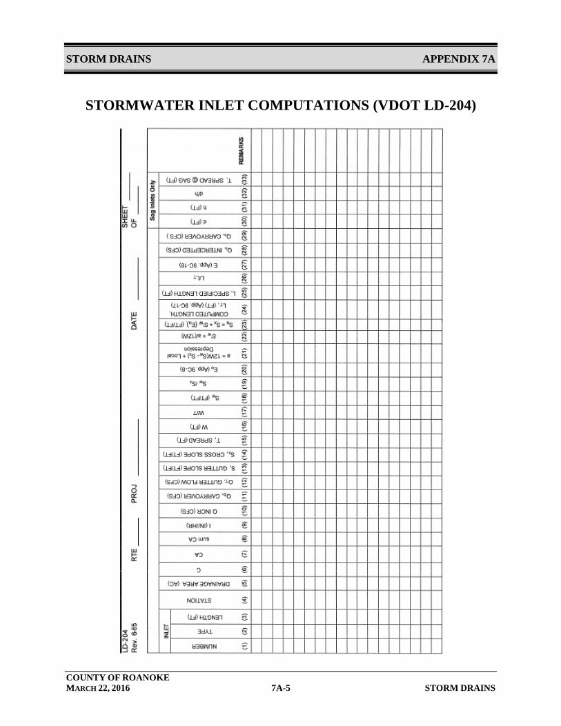
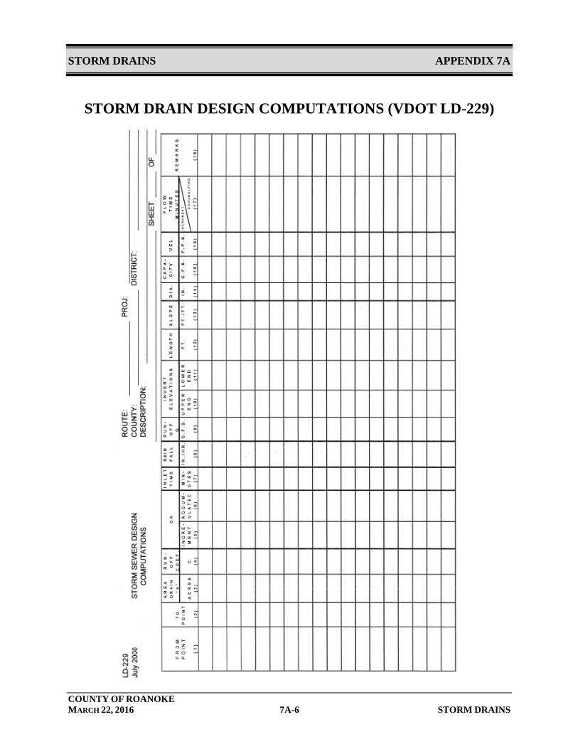
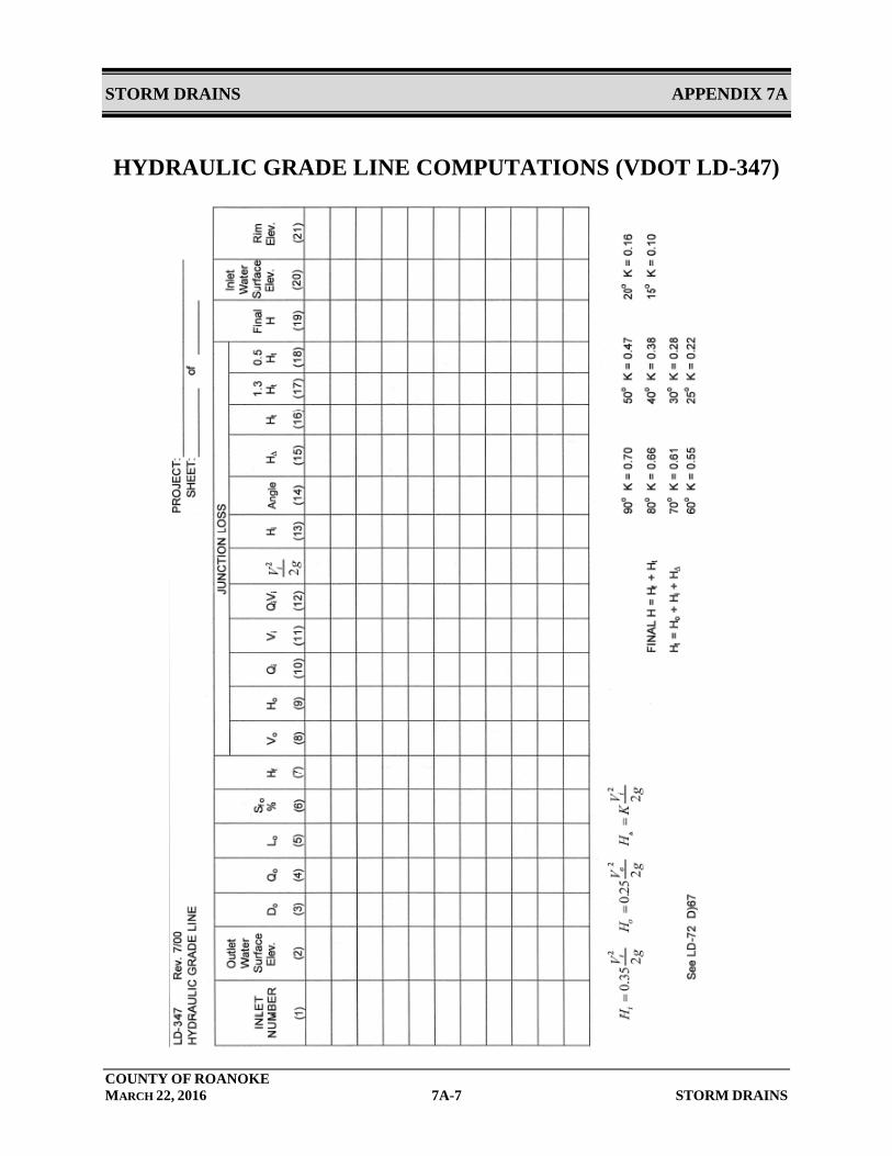
Manual computations use design equations and nomographs. Results are documented on VDOT work sheets. Copies of these forms are included in Appendix 7A.
• Form LD-204 Stormwater Inlet Computations
• Form LD-229 Storm Drain Design Computations
• Form LD-347 Hydraulic Grade Line Computations
There are a number of computer programs available to design storm drainage systems. Any of these computer programs will be acceptable if their methodologies are based on the same equations and nomographs accepted by VDOT, and if they provide the same documentation of inputs, assumptions, and output as are contained on VDOT’s work sheets. Computation methods are explained in detail, including comprehensive design examples, in the VDOT Drainage Manual.
7.2.2 Hydrology
A. Design Flow Methodology
Calculations establishing the design flow shall be submitted with the Stormwater Management Plan. Design flows shall be based on ultimate build-out of the contributing watershed based on the current Comprehensive Plan.
7.2.3 Design Flows
The following minimum storm frequencies shall be used:
A. Inlets
Inlets shall be designed for storm frequencies and intensities consistent with the VDOT Drainage Manual. For reference, the VDOT table and its accompanying notes have been included in Appendix 7A.
STORM DRAINS CHAPTER 7
COUNTY OF ROANOKE MARCH 22, 2016 7-3 STORM DRAINS
B. Storm Drains
Storm drains shall be designed for the storm frequencies and intensities consistent with the VDOT Drainage Manual. For reference, the VDOT table and its accompanying notes have been included in Appendix 7A. Unless otherwise specified by the VDOT Drainage Manual, a 10-year frequency design storm shall be used in developing design flows.
7.2.4 Measures to Convey Stormwater Runoff to Inlets
A. Pavement Drainage
One objective in the site design is to collect and remove stormwater runoff from critical areas as efficiently as possible. A properly designed system will ensure that roadway surfaces are free of stormwater accumulations, and will protect the public from unnecessary hazards associated with water ponding and sheet flow. Except where porous pavement is used, road pavement shall be sloped transversely to drain stormwater from the roadway. A minimum cross slope of 2 percent should be applied to all roads, both primary and secondary. Greater slope should be considered where poor drainage is anticipated. Drainage structures associated with medians, curbs, and gutters should be designed to minimize accumulation of water onto travel lanes of roadways. For additional information concerning drainage of highway pavements, refer to FHWA HEC No. 12.
B. Curb and Gutter
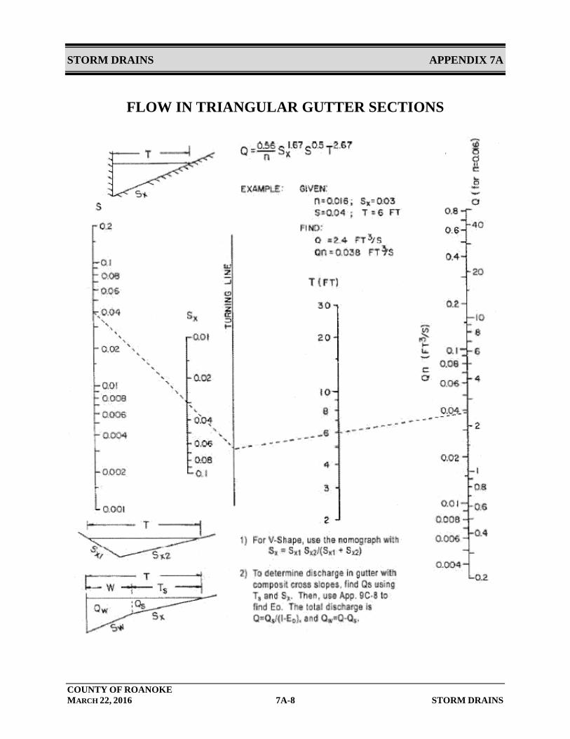
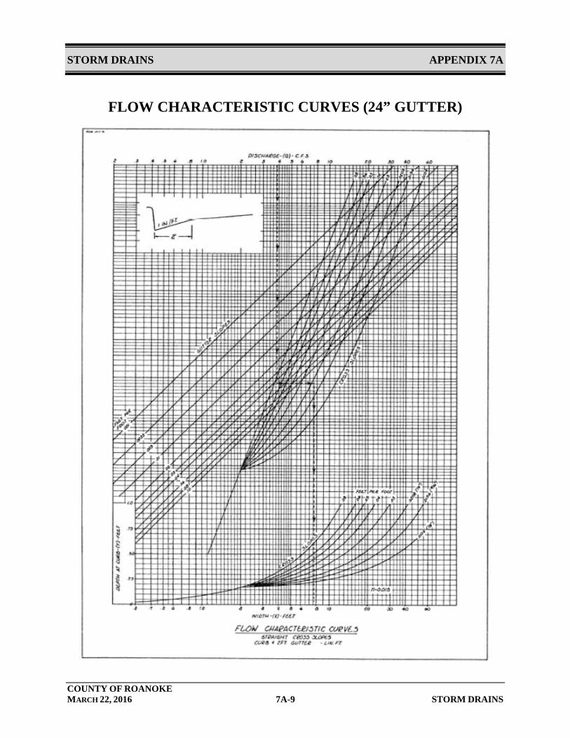
Curb and gutter at the edge of pavements may be used to collect stormwater runoff from roadways. Curbing captures stormwater runoff and directs it to stormwater collection inlets while protecting adjacent properties from flooding and erosion due to sheet flow runoff from the impervious roadways. A curb and gutter forms a triangular conveyance channel. When a storm occurs, the runoff from the road creates a spread of water from the curb. The curb and gutter must be designed to convey this flow and prevent the spread of water from impacting traffic. The spread width of flow is determined by using VDOT nomographs or acceptable hydrological
STORM DRAINS CHAPTER 7
COUNTY OF ROANOKE MARCH 22, 2016 7-4 STORM DRAINS
design software. For curb and gutter flow, a Manning’s n value of 0.015 is used in the computational analysis. See Appendix 7A for width of maximum allowable spread.
Curb and gutter dimensions and design shall meet VDOT Standards.
C. Open Channels
Open channels may be used to collect site drainage and convey it to a storm drain inlet. Design requirements for open channels are covered in Chapter 5.
7.2.5 Storm Drain Inlets
A. General
Storm drain inlets are used to collect stormwater runoff from roads, walks, or low elevations during storm events and provide a method for passing the stormwater into the storm drain system. This is usually accomplished by placing storm drain inlets at regular intervals, low points, or at key locations to intercept flows and control the stormwater spread width. The design criteria for limiting the spread of water on travel lanes are contained in the VDOT Drainage Manual. The current design table and its notes have been included in Appendix 7A There are several different types of storm drain inlets which can be used to meet this purpose, and the designer shall choose the proper inlet structure based upon site conditions and design conditions to maximize the drainage efficiencies.
• Curb • Grate • Slotted Drain/Trench • Combination
Drainage and Stormwater management plans shall include a contour plan with sufficient contours shown to indicate proper drainage.
B. Curb Inlets
Curb inlets are vertical openings in the curb covered by a top slab. These inlets can convey large quantities of water, but also allow for large amounts of debris to enter the storm drain system.
STORM DRAINS CHAPTER 7
COUNTY OF ROANOKE MARCH 22, 2016 7-5 STORM DRAINS
Curb inlets shall be used to the maximum extent possible for pavement drainage.
C. Grate Inlets
Grate inlets are horizontal grates usually used in depressed medians or other low elevations. Grate inlets are often referred to as drop inlets or DIs. Grate inlets shall be avoided in paved areas. Where they are used in pavement, inlet grates shall be bicycle safe.
D. Combination Inlets
Combination inlets combine both the vertical opening used by curb inlets and the horizontal grate used in grate inlets. These inlets are often used when the inlet chamber is required to be under the gutter or street pavement away from the sidewalk or other utilities. Combination inlets shall be avoided where possible. Where they are used, they shall have bicycle safe grates.
E. Slotted Drain Inlets
Slotted drain inlets are a narrow slotted opening which can collect flow at a median barrier or curb. These inlets are usually located in areas of limited space and can be used to intercept sheet flow, or collect gutter flow to help reduce ponding depth or spreading at grate inlets.
F. Inlet Locations
Inlets shall be located to meet the design requirements of the VDOT Drainage Manual for maximum spread width. In addition, inlets shall be provided, regardless of contributing drainage area as follows:
• Sag points in the gutter grade; • Upstream of median breaks, crosswalks, and street intersections; • Immediately upstream and downstream of bridges; • On side streets at intersections, where flow is approaching the
main line; • Behind curbs, shoulders, or sidewalks to drain low areas or
intercept concentrated flow; and
STORM DRAINS CHAPTER 7
COUNTY OF ROANOKE MARCH 22, 2016 7-6 STORM DRAINS
• Any low elevation in the grade.
Inlets shall be avoided in pathways likely to be used by pedestrians or bicyclists.
G. Access
All inlets shall have a removable grate or manhole cover to allow access for clean out. All structures greater than 3 feet in depth shall be a minimum of 4 feet in diameter for maintenance access.
H. Inlet Capacities
The capacities of each inlet type are contained in the VDOT Drainage Manual. Documentation of inlet capacity shall be made on VDOT Form LD-204, Stormwater Inlet Computations or equivalent.
I. Separation of Pipes in Inlets
Where two or more pipes enter a concrete structure at or near the same elevation, a 6” minimum horizontal clearance must be maintained between the pipes. Additional clearance between pipes shall be provided if required to protect the structural integrity of the structure.
J. Karst Terrain
Water tight joints are required where storm drainage pipe are located in karst terrain. Additionally, an A-lock premium gasket or boot is required for the pipe connection to the storm drainage structure to prevent water loss at the structure connection.
7.2.6 Storm Drain Pipes
A. Flow Capacity
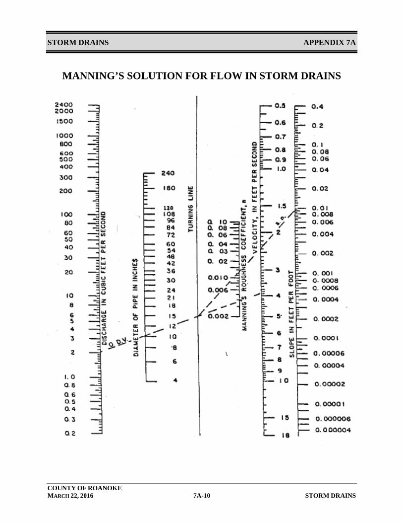
Based on the size and slope of the storm drain, the design capacity for a pipe flowing full can be determined using Manning’s equation. Q = A x 1.49/n x R2/3 x S1/2
Where: Q = Flow in the pipe (cfs) A = Area of the pipe (ft2)
STORM DRAINS CHAPTER 7
COUNTY OF ROANOKE MARCH 22, 2016 7-7 STORM DRAINS
R = Hydraulic radius, for circular pipe R=Diameter/4 (ft) S = Storm drain slope (ft/ft) n = Pipe roughness coefficient The design flow capacity of a storm drain shall comply with the design frequencies set forth in VDOT Drainage Manual as shown in the table in Appendix 7A. In a roadway underpass, or depressed section, where ponded water can only be removed through the storm drain system, a 100-year frequency storm event shall be used to design the storm drain at the sag point. Storm drain flow capacities shall be documented on VDOT Form LD-229, Storm Drain Design Computations or equivalent form.
B. Storm Drain Slope
To deter the settling of debris and sediment in the storm drain pipe, the pipe shall be designed to ensure positive slope and maintain a minimum velocity of 3 feet per second during a 2-year frequency storm or a minimum of 0.5% slope, whichever is more restrictive. A minimum drop across the structure of 0.1’ shall be provided in all storm drainage structures. The maximum pipe velocity, based on the 10-year peak flow rate, in any storm drain shall be in accordance with VDOT requirements based on the storm drain material, but in no event shall it be greater than 20 fps.
Storm drains shall be sloped to meet the velocity requirement set in this chapter. Slopes greater than 16 percent shall be avoided if possible. If unavoidable, drop structures shall be utilized in steeper terrain. In addition, storm drains with slopes steeper than 16% must have anchor blocks for support.
C. Pipe Size
All storm drains located in public easements or rights-of-way shall be a minimum of 15-inch diameter. Pipe size shall not be reduced along the direction of the flow, except as required for proper operation of stormwater management facilities.
D. Access
Regardless of pipe size, a cleanout access point, either an inlet, manhole, or junction box shall be provided at a maximum of every 300 feet of pipe.

STORM DRAINS CHAPTER 7
COUNTY OF ROANOKE MARCH 22, 2016 7-8 STORM DRAINS
Cleanouts can be used for pipes 6” and smaller. All pipes over 6” require an inlet or manhole.
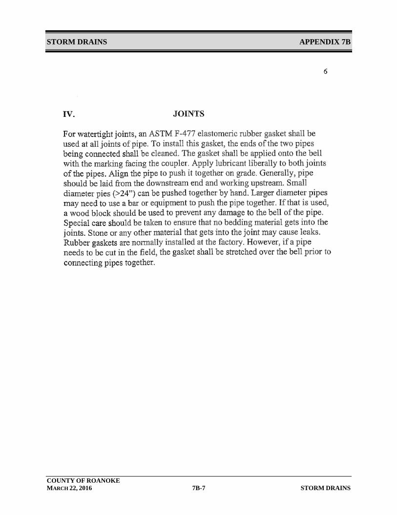
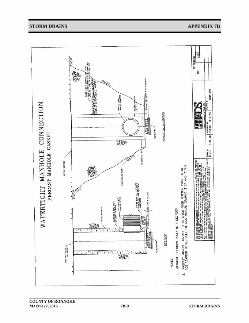
E. Joints
At a minimum, all joints shall be “soil tight”. The County strongly recommends the use of “water-tight” joints under pavements and areas that are stormwater “hotspots”. “Water-tight” joints are required for karst terrain. See Section IV and corresponding ADS detail in Appendix 7B for additional info in water tight joints.
7.2.7 Determination of Hydraulic Grade Line
A. General
The hydraulic grade line represents the free water surface elevation of water in a pipe system. Where the hydraulic grade line is above the top of a pipe, the pipe is flowing under pressure. The hydraulic grade line in a manhole or other structure is the elevation to which water will rise.
Hydraulic grade lines shall be calculated and evaluated for all storm drains. The hydraulic grade line shall be calculated using VDOT methods and equations that are fully described in the VDOT Drainage Manual. Calculations shall be documented on VDOT Form LD-347, Hydraulic Grade Line Computations, or equivalent. A copy of this form is included in Appendix 7A. Hydraulic grade lines can also be calculated with design software (ie Storm sewer, etc.) The hydraulic grade line shall not exceed any critical elevation during the design storm. Critical elevations include rising above the ground elevation at inlets or other structures, or reaching an elevation where storm flow could back-up to cause flooding damage.
The calculation of the hydraulic grade line begins at the system outfall and proceeds upstream to each structure on the system. The calculation is based on the principal of conservation of energy as shown below and includes major and minor energy losses:
HGLus = HGLds + Hf + Hm Where:
HGLus = Elevation of hydraulic grade line at the upstream structure Hm = Summation of minor head losses (junctions, bends, etc.) Hf = Pipe friction loss
STORM DRAINS CHAPTER 7
COUNTY OF ROANOKE MARCH 22, 2016 7-9 STORM DRAINS
HGLds = Elevation of hydraulic grade line at the downstream structure
Major head losses are attributable to friction losses within the pipe. Minor head losses include losses from:
• Junctions • Exits • Entrances • Bends in Pipes • Access holes • Conflict pipes • Plunging flow • Expansions and contractions • Appurtenances such as weirs, diverters, valves and meters
B. Outfall Conditions
The hydraulic grade line starts at the system outfall. At this point the hydraulic grade line shall be the actual tailwater elevation or the elevation of 0.8 times the diameter of the outlet pipe, whichever is higher. If the system discharges into a detention or retention pond, the hydraulic grade shall start at the 10 year water surface elevation.
C. Pipe Friction Losses
The friction slope is the energy slope for that run of pipe. The friction slope is determined by inserting pipe information and design flow into Manning’s equation and solving for S (slope). The total friction headloss in the run of pipe is the friction slope multiplied by the length of the run.
Where the hydraulic grade line falls below the crown of the pipe, the elevation of normal flow is the hydraulic grade line.
D. Junction Losses
1. General
Junction head losses are the summation of entrance (Hi), exit (Ho), and bend losses (HΔ). When calculating junction losses it is important to use actual flow velocities. If pipes are flowing partially full, then partially full velocities are used.
STORM DRAINS CHAPTER 7
COUNTY OF ROANOKE MARCH 22, 2016 7-10 STORM DRAINS
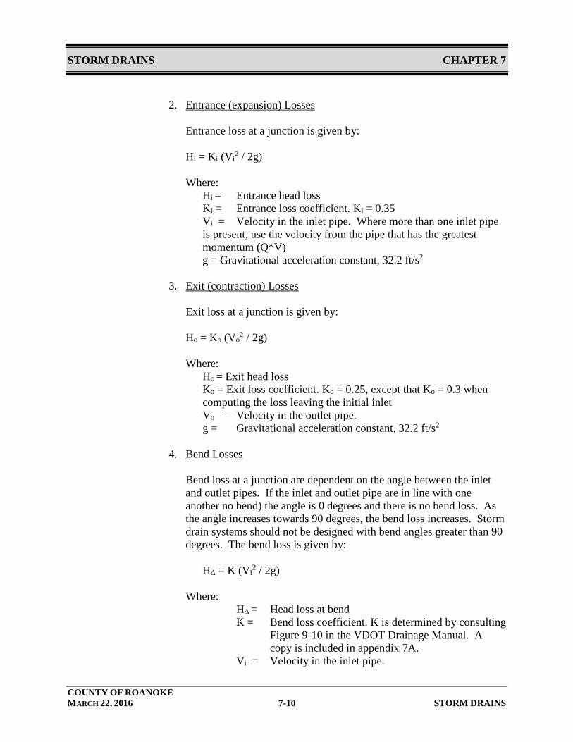
2. Entrance (expansion) Losses Entrance loss at a junction is given by: Hi = Ki (Vi
2 / 2g) Where:
Hi = Entrance head loss Ki = Entrance loss coefficient. Ki = 0.35
Vi = Velocity in the inlet pipe. Where more than one inlet pipe is present, use the velocity from the pipe that has the greatest momentum (Q*V) g = Gravitational acceleration constant, 32.2 ft/s2
3. Exit (contraction) Losses
Exit loss at a junction is given by: Ho = Ko (Vo
2 / 2g) Where: Ho = Exit head loss
Ko = Exit loss coefficient. Ko = 0.25, except that Ko = 0.3 when computing the loss leaving the initial inlet Vo = Velocity in the outlet pipe. g = Gravitational acceleration constant, 32.2 ft/s2
4. Bend Losses
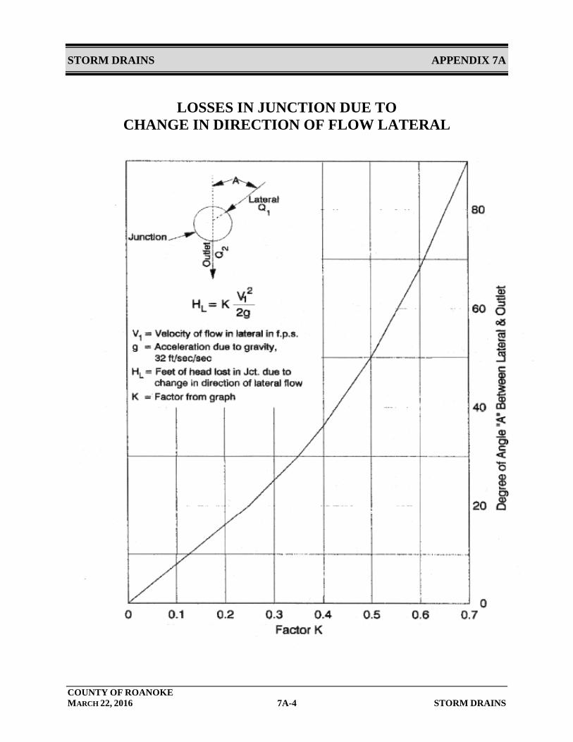
Bend loss at a junction are dependent on the angle between the inlet and outlet pipes. If the inlet and outlet pipe are in line with one another no bend) the angle is 0 degrees and there is no bend loss. As the angle increases towards 90 degrees, the bend loss increases. Storm drain systems should not be designed with bend angles greater than 90 degrees. The bend loss is given by:
HΔ = K (Vi
2 / 2g)
Where: HΔ = Head loss at bend
K = Bend loss coefficient. K is determined by consulting Figure 9-10 in the VDOT Drainage Manual. A copy is included in appendix 7A.
Vi = Velocity in the inlet pipe.
STORM DRAINS CHAPTER 7
COUNTY OF ROANOKE MARCH 22, 2016 7-11 STORM DRAINS
g = Gravitational acceleration constant, 32.2 ft/s2
5. Plunging Losses
Where surface inlet inflow is 20 percent or more of the total flow through a junction, or when a lateral pipe enters a junction with its invert elevation above the crown of the outgoing pipe and the flow in the lateral pipe is 20 percent or more of the total flow through the junction, the total headloss from the structure (Hi + Ho + HΔ) shall be multiplied by 1.3 (increased by 30 percent). This adjustment is cumulative with the adjustment for inlet shaping.
6. Inlet Shaping
Inlet shaping refers to how the invert is shaped to provide smooth flow through the structure and is required in all manholes and inlets. When VDOT Standard IS-1, inlet shaping, is used in a structure the total headloss from the structure (Hi + Ho + HΔ) shall be multiplied by 0.5 (decreased by 50 percent). This adjustment is cumulative with the adjustment for plunging losses.
7.2.8 100-Year Conditions
Where there is the possibility of building structures flooding, conditions during the 100-year storm shall be analyzed to verify that all existing and proposed structures do not flood. Flow from the 100-year storm may be carried overland as well as by the storm drain system.
7.2.9 Materials
A. Structures
• All stormwater structures (inlets, manholes, and junction boxes) located in public easements or rights-of-way shall be precast or cast-in-place concrete. All structures, frames, grates, and covers shall be in accordance with VDOT Standards and VDOT Specifications.
• All storm drain structures over four (4) feet in depth must have steps.
STORM DRAINS CHAPTER 7
COUNTY OF ROANOKE MARCH 22, 2016 7-12 STORM DRAINS
B. Storm Drain Pipe
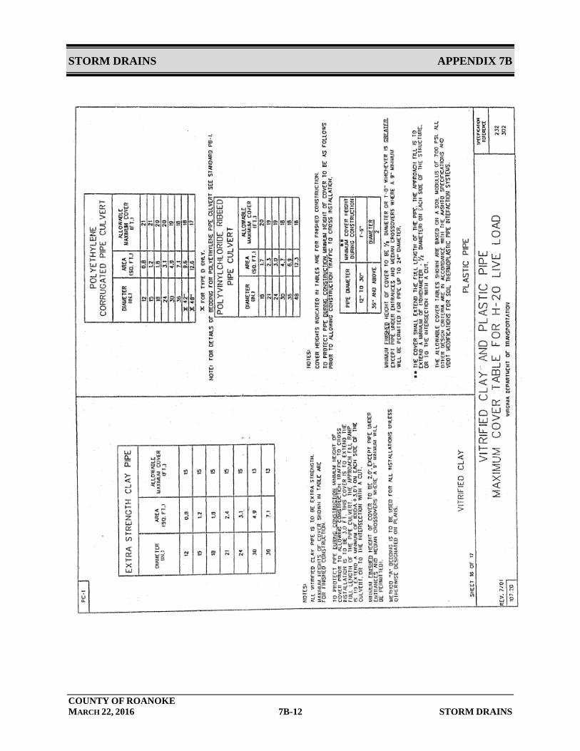
• Storm drains in the VDOT right-of-way shall be VDOT approved materials in accordance with VDOT IIM-LD-121.15 and VDOT Standard PC-1. • Storm drains not in the VDOT right-of way shall be:
o Reinforced concrete pipe (RCP). o Corrugated high-density polyethylene pipe (HDPE) with an integrally formed smooth interior is allowed for sizes 48-inch diameter or smaller. HDPE pipe is allowed for pipe slopes less than 12% and with a velocity 12 fps or less. HDPE culvert pipe cover must be in accordance with the County of Roanoke Inspection Specifications for HDPE Pipe. A copy of this document is included in Appendix 7B. o Culverts 60 inches in diameter or greater may be Corrugated Aluminized Metal Pipe (CAMP) or corrugated aluminum with a minimum 14 gauge metal. o The minimum cover for all pipes is two (2) feet measured from the final surface. Special applications for less than two (2) feet of cover will be reviewed and approved by the County Engineer individually. The maximum cover for storm drainage pipes shall at a minimum comply with the requirements of the Virginia Department of Transportation Design Manual.
7.2.10 Structural Design
All inlet structures, frames and grates; and pipes shall be designed to withstand a HS-20 loading, unless a pipe crosses a railroad, in which case the pipe shall be designed for railroad loads. The structural design shall consider the depth of cover, trench width and condition, bedding type, backfill material, and compaction.
7.3 Installation
All inlets, pipes, and associated structures shall be installed in accordance with VDOT Specifications and the manufacturer’s recommendations. The characteristics of the trench, bedding, and pipe material all impact the structural strength of the pipe system. The installed pipe conditions shall comply with the design assumptions and calculations.

STORM DRAINS CHAPTER 7
COUNTY OF ROANOKE MARCH 22, 2016 7-13 STORM DRAINS
HDPE pipe installation shall comply with the County of Roanoke Inspection Specifications for HDPE Pipe. A copy of this document is included in Appendix 7B.
Storm drains shall not be installed through contaminated soils or groundwater.
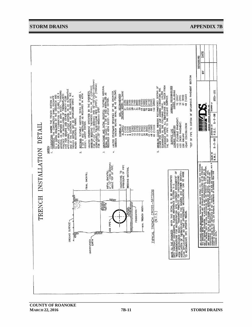
7.3.1 Bedding Material
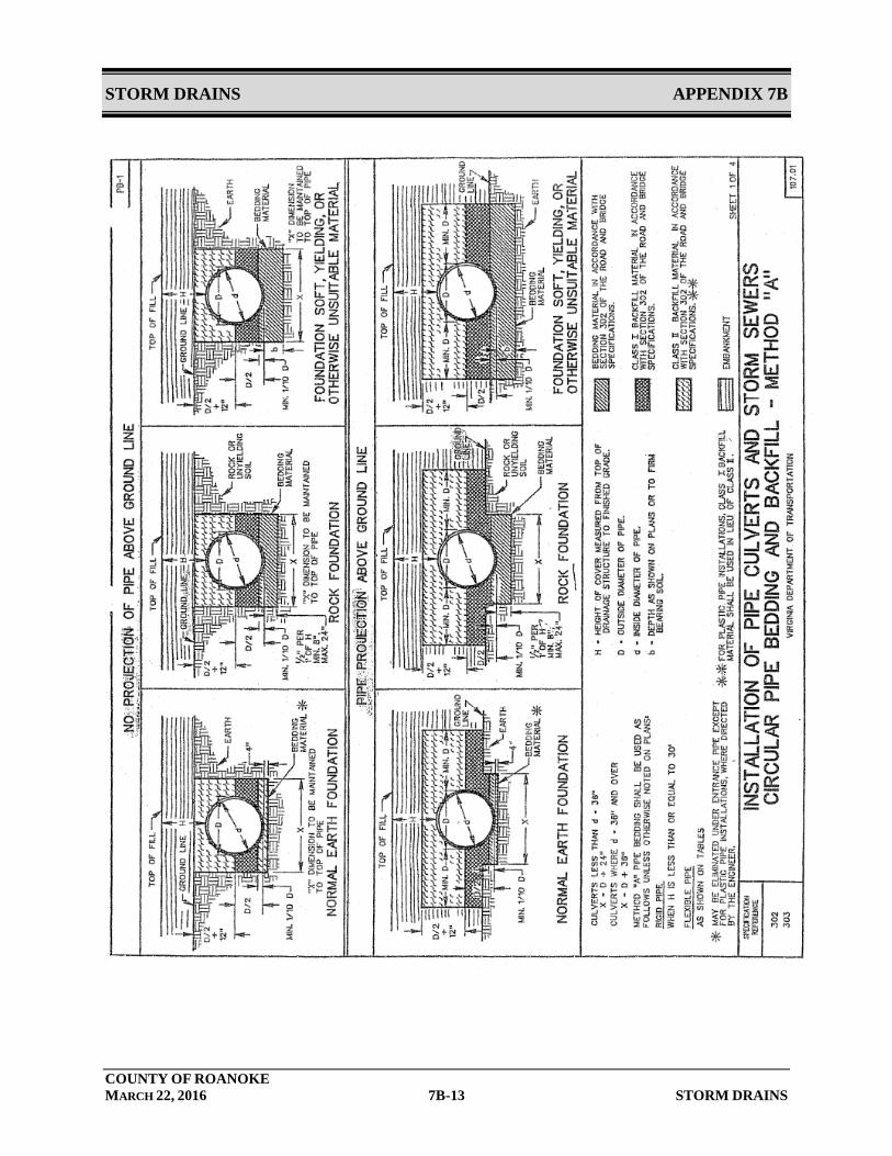
Bedding material and installation shall comply with the requirements of the VDOT Specifications. Use Class I backfill (crusher run and #21) to one foot over the pipe for HDPE, up to the spring line for RCP. #57 stone is not allowed as pipe bedding.
7.3.2 Backfill
Backfill shall be suitable material and shall be placed and compacted in accordance with the VDOT Specifications (PB-1 detail). Use Class I backfill (crusher run) to one foot over the pipe for HDPE, and up to the spring line for RCP. The minimum cover for all pipes is two (2) feet measured from the final surface. Special applications for less than two (2) feet of cover will be reviewed and approved by the County Engineer individually. Additional minimum depth of cover shall be provided if recommended by the manufacturer. All pipe installed must be inspected and approved by the County’s Inspector prior to any backfill being placed. The Contractor must provide 24 hour notice to County prior to installing backfill so that County staff can be present for inspections.
7.3.3 Separation of Utilities
Where storm drains cross other utilities, at least 1-foot of vertical separation shall be provided. Where 1-foot of vertical separation cannot be provided, special provisions shall be made in the bedding and backfill to avoid settlement that could cause point loadings on the storm drain or other utility. Water lines shall not pass through a storm drain inlet or manhole.
7.4 Environmental Impacts
Construction or modifications to storm drains shall comply with all applicable laws and regulations. The applicant is responsible for procuring all necessary permits.
STORM DRAINS CHAPTER 7
COUNTY OF ROANOKE MARCH 22, 2016 7-14 STORM DRAINS
7.5 Erosion Protection at Outfalls
Erosion protection at storm drain outlets shall be provided in accordance with the outlet protection standards contained in the VA E&SC Handbook and the VDOT Drainage Manual.
7.6 Maintenance Requirements
The permittee is responsible for maintenance of storm drains until construction is complete, including final clean up and site stabilization, to the satisfaction of the County.
STORM DRAINS APPENDIX 7A
COUNTY OF ROANOKE MARCH 22, 2016 7A-1 STORM DRAINS
APPENDIX 7A
AIDS FOR STORM DRAIN SYSTEM DESIGN
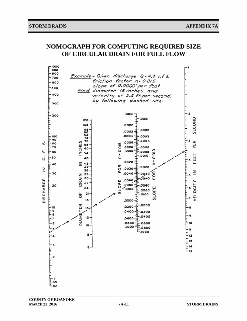
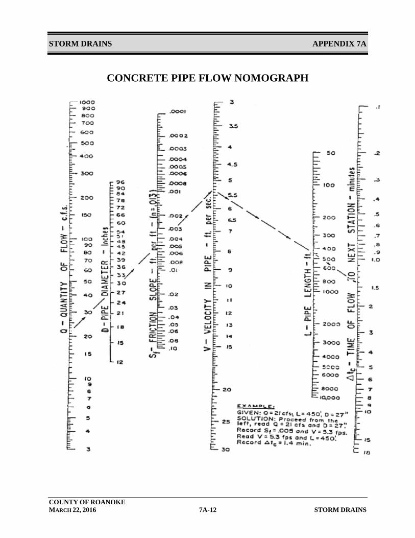
FROM CHAPTER 9, VDOT DRAINAGE MANUAL Table 9-1, Criteria for Inlet Design Table 9-2, Design Frequencies for Storm Drain Conduit Notes that accompany Table 9-1 and Table 9-2 Figure 9-10, Losses in Junction due to Change in Direction of Flow Lateral Appendix 9B-1, LD 204 Stormwater Inlet Computations Appendix 9B-2, LD 229 Storm Drain Design Computations Appendix 9B-3, LD 347 Hydraulic Grade Line Computations Appendix 9C-1, Flow in Triangular Gutter Sections Appendix 9C-3, Flow Characteristic Curves (24” Gutter)- VDOT Standard Appendix 9C-23, Manning’s Solution for Flow in Storm Drains Appendix 9C-24, Nomograph for Computing Required Size of Circular Drain for Full Flow Appendix 9C-25, Concrete Pipe Flow Nomograph
STORM DRAINS APPENDIX 7A
COUNTY OF ROANOKE MARCH 22, 2016 7A-2 STORM DRAINS
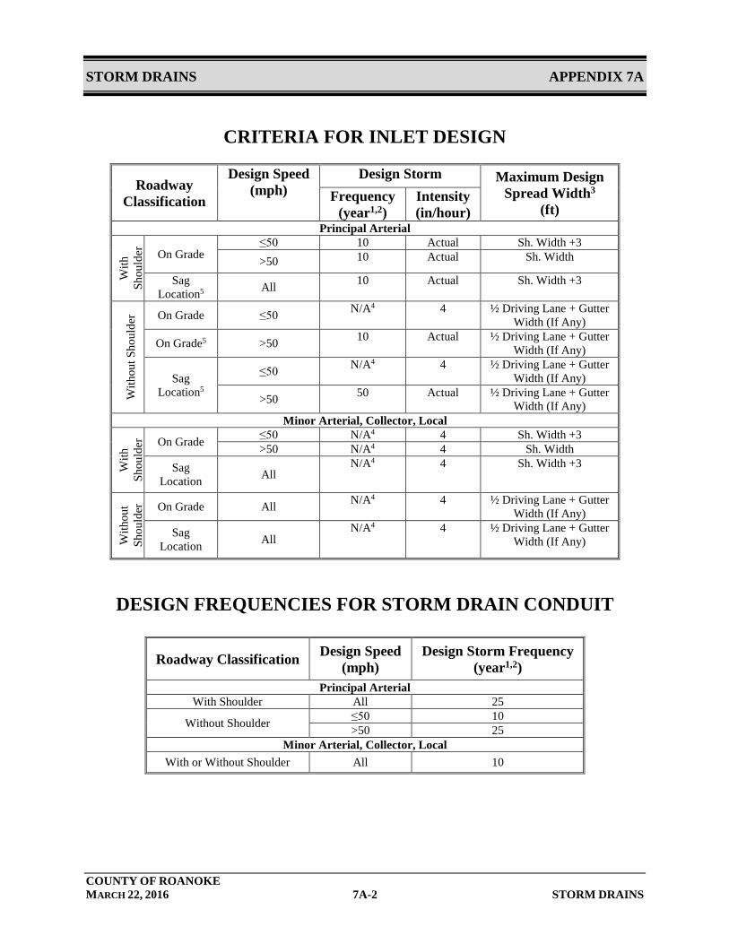
CRITERIA FOR INLET DESIGN
Roadway Classification
Design Speed (mph)
Design Storm Maximum Design Spread Width3
(ft) Frequency
(year1,2) Intensity (in/hour)
Principal Arterial
With
Sh
ould
er
On Grade ≤50 10 Actual Sh. Width +3 >50 10 Actual Sh. Width
Sag Location5 All 10 Actual Sh. Width +3
With
out S
houl
der On Grade ≤50 N/A4 4 ½ Driving Lane + Gutter
Width (If Any)
On Grade5 >50 10 Actual ½ Driving Lane + Gutter Width (If Any)
Sag Location5
≤50 N/A4 4 ½ Driving Lane + Gutter Width (If Any)
>50 50 Actual ½ Driving Lane + Gutter Width (If Any)
Minor Arterial, Collector, Local
With
Sh
ould
er On Grade ≤50 N/A4 4 Sh. Width +3
>50 N/A4 4 Sh. Width Sag
Location All N/A4 4 Sh. Width +3
With
out
Shou
lder
On Grade All N/A4 4 ½ Driving Lane + Gutter Width (If Any)
Sag Location All
N/A4 4 ½ Driving Lane + Gutter Width (If Any)
DESIGN FREQUENCIES FOR STORM DRAIN CONDUIT
Roadway Classification Design Speed (mph)
Design Storm Frequency (year1,2)
Principal Arterial With Shoulder All 25
Without Shoulder ≤50 10 >50 25
Minor Arterial, Collector, Local With or Without Shoulder All 10
STORM DRAINS APPENDIX 7A
COUNTY OF ROANOKE MARCH 22, 2016 7A-3 STORM DRAINS
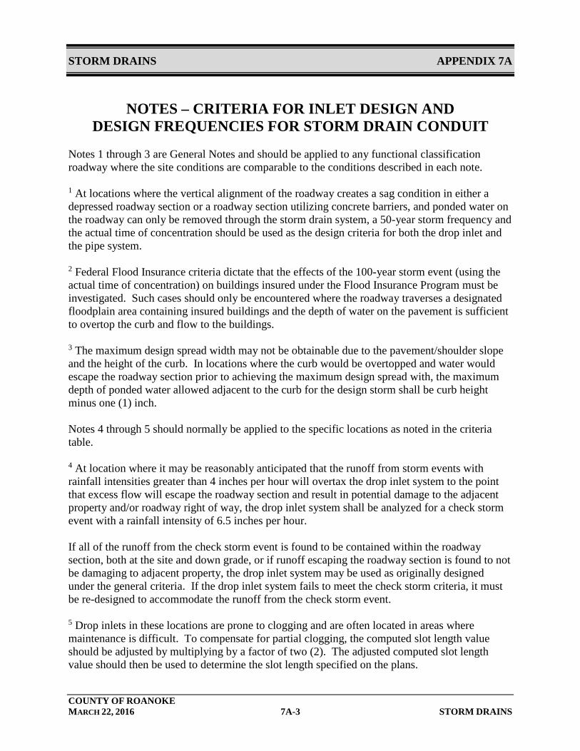
NOTES – CRITERIA FOR INLET DESIGN AND DESIGN FREQUENCIES FOR STORM DRAIN CONDUIT
Notes 1 through 3 are General Notes and should be applied to any functional classification roadway where the site conditions are comparable to the conditions described in each note. 1 At locations where the vertical alignment of the roadway creates a sag condition in either a depressed roadway section or a roadway section utilizing concrete barriers, and ponded water on the roadway can only be removed through the storm drain system, a 50-year storm frequency and the actual time of concentration should be used as the design criteria for both the drop inlet and the pipe system. 2 Federal Flood Insurance criteria dictate that the effects of the 100-year storm event (using the actual time of concentration) on buildings insured under the Flood Insurance Program must be investigated. Such cases should only be encountered where the roadway traverses a designated floodplain area containing insured buildings and the depth of water on the pavement is sufficient to overtop the curb and flow to the buildings. 3 The maximum design spread width may not be obtainable due to the pavement/shoulder slope and the height of the curb. In locations where the curb would be overtopped and water would escape the roadway section prior to achieving the maximum design spread with, the maximum depth of ponded water allowed adjacent to the curb for the design storm shall be curb height minus one (1) inch. Notes 4 through 5 should normally be applied to the specific locations as noted in the criteria table. 4 At location where it may be reasonably anticipated that the runoff from storm events with rainfall intensities greater than 4 inches per hour will overtax the drop inlet system to the point that excess flow will escape the roadway section and result in potential damage to the adjacent property and/or roadway right of way, the drop inlet system shall be analyzed for a check storm event with a rainfall intensity of 6.5 inches per hour. If all of the runoff from the check storm event is found to be contained within the roadway section, both at the site and down grade, or if runoff escaping the roadway section is found to not be damaging to adjacent property, the drop inlet system may be used as originally designed under the general criteria. If the drop inlet system fails to meet the check storm criteria, it must be re-designed to accommodate the runoff from the check storm event. 5 Drop inlets in these locations are prone to clogging and are often located in areas where maintenance is difficult. To compensate for partial clogging, the computed slot length value should be adjusted by multiplying by a factor of two (2). The adjusted computed slot length value should then be used to determine the slot length specified on the plans.
STORM DRAINS APPENDIX 7A
COUNTY OF ROANOKE MARCH 22, 2016 7A-4 STORM DRAINS
LOSSES IN JUNCTION DUE TO CHANGE IN DIRECTION OF FLOW LATERAL
STORM DRAINS APPENDIX 7A
COUNTY OF ROANOKE MARCH 22, 2016 7A-5 STORM DRAINS
STORMWATER INLET COMPUTATIONS (VDOT LD-204)
STORM DRAINS APPENDIX 7A
COUNTY OF ROANOKE MARCH 22, 2016 7A-6 STORM DRAINS
STORM DRAIN DESIGN COMPUTATIONS (VDOT LD-229)
STORM DRAINS APPENDIX 7A
COUNTY OF ROANOKE MARCH 22, 2016 7A-7 STORM DRAINS
HYDRAULIC GRADE LINE COMPUTATIONS (VDOT LD-347)
STORM DRAINS APPENDIX 7A
COUNTY OF ROANOKE MARCH 22, 2016 7A-8 STORM DRAINS
FLOW IN TRIANGULAR GUTTER SECTIONS
STORM DRAINS APPENDIX 7A
COUNTY OF ROANOKE MARCH 22, 2016 7A-9 STORM DRAINS
FLOW CHARACTERISTIC CURVES (24” GUTTER)
STORM DRAINS APPENDIX 7A
COUNTY OF ROANOKE MARCH 22, 2016 7A-10 STORM DRAINS
MANNING’S SOLUTION FOR FLOW IN STORM DRAINS
STORM DRAINS APPENDIX 7A
COUNTY OF ROANOKE MARCH 22, 2016 7A-11 STORM DRAINS
NOMOGRAPH FOR COMPUTING REQUIRED SIZE OF CIRCULAR DRAIN FOR FULL FLOW
STORM DRAINS APPENDIX 7A
COUNTY OF ROANOKE MARCH 22, 2016 7A-12 STORM DRAINS
CONCRETE PIPE FLOW NOMOGRAPH
STORM DRAINS APPENDIX 7B
COUNTY OF ROANOKE MARCH 22, 2016 7B-1 STORM DRAINS
APPENDIX 7B
INSTALLATION PROCEDURES
FROM ROANOKE COUNTY Inspection Specifications for HDPE PIPE
STORM DRAINS APPENDIX 7B
COUNTY OF ROANOKE MARCH 22, 2016 7B-2 STORM DRAINS

STORM DRAINS APPENDIX 7B
COUNTY OF ROANOKE MARCH 22, 2016 7B-3 STORM DRAINS
STORM DRAINS APPENDIX 7B
COUNTY OF ROANOKE MARCH 22, 2016 7B-4 STORM DRAINS

STORM DRAINS APPENDIX 7B
COUNTY OF ROANOKE MARCH 22, 2016 7B-5 STORM DRAINS
STORM DRAINS APPENDIX 7B
COUNTY OF ROANOKE MARCH 22, 2016 7B-6 STORM DRAINS
STORM DRAINS APPENDIX 7B
COUNTY OF ROANOKE MARCH 22, 2016 7B-7 STORM DRAINS
STORM DRAINS APPENDIX 7B
COUNTY OF ROANOKE MARCH 22, 2016 7B-8 STORM DRAINS
STORM DRAINS APPENDIX 7B
COUNTY OF ROANOKE MARCH 22, 2016 7B-9 STORM DRAINS

STORM DRAINS APPENDIX 7B
COUNTY OF ROANOKE MARCH 22, 2016 7B-10 STORM DRAINS
STORM DRAINS APPENDIX 7B
COUNTY OF ROANOKE MARCH 22, 2016 7B-11 STORM DRAINS
STORM DRAINS APPENDIX 7B
COUNTY OF ROANOKE MARCH 22, 2016 7B-12 STORM DRAINS
STORM DRAINS APPENDIX 7B
COUNTY OF ROANOKE MARCH 22, 2016 7B-13 STORM DRAINS