storage backups
TRANSCRIPT

8/7/2019 Storage Backups
http://slidepdf.com/reader/full/storage-backups 1/23
Cylinder-head-sector, also known as CHS, was an early method for giving addresses to each physical block of data on a hard disk drive. In the case of floppy drives, for which the same exact
diskette medium can be truly low-level formatted to different capacities, this is still true.
Though CHS values no longer have a direct physical relationship to the data stored on disks,
pseudo CHS values (which can be translated by disk electronics or software) are still being used by many utility programs.
Heads
Data is written to and read from the surface of a platter by a device called a head. Naturally, a platter has 2 sides and thus 2 surfaces on which data could be manipulated; usually there are 2
heads per platter²one on each side, but not always. (Sometimes the term side is substituted for head, since platters might be separated from their head assemblies; as is definitely the case with
the removable media of a floppy drive.)
[edit] Tracks
The tracks are the thin concentric circular strips on a floppy disk or platter surface which
comprise the magnetic medium to which data is written by the drive heads. These magnetic stripsform a circle and are (therefore) two-dimensional. At least one head is required to read a single
track. All information stored on the hard disk is recorded in tracks.
[edit] Cylinders
A cylinder comprises the same track number on each platter, spanning all such tracks across each platter surface that is able to store data (without regard to whether or not the track is "bad").
Thus, it is a three-dimensional structure. Any track comprising part of a specific cylinder can bewritten to and read from while the actuator assembly remains stationary, and one way in which
hard drive manufacturers have increased drive access speed has been by increasing the number of platters which can be read at the same time.
As larger hard disks have come into use, a cylinder has become also a logical, rather than a
physical, disk structure: standardised at 16,065 sectors (i.e. 255 tracks multiplied by 63 sectors per track).
[edit] Sectors
Tracks are subdivided. Each subdivision is called a sector , which is the smallest storage unit on ahard drive. Typically, a sector will hold 512 bytes of information.
[1]Some vendors of hard
drives, and some software developers, are attempting to create a new standard for the future byrevising the amount of data stored in a sector to 4,096 bytes.[2]
[edit] Blocks and Clusters

8/7/2019 Storage Backups
http://slidepdf.com/reader/full/storage-backups 2/23
In MSDOS and Windows communities the phrases allocation unit or cluster are usedinterchangeably to represent the group of sectors. Cluster is the smallest unit for the file system.
The Unix communities employ the term block to refer to a sector or group of sectors. For
example, the Linux fdisk utility normally displays partition table information using 1024-byte
blocks, but also uses the word sector to help describe a disk's size in the phrase, 63 sectors per track .
Note: The terms cluster and block are also often used separately from the context of physicaldisks. It is still, by convention, a power of 2 multiple of 512 bytes.
[edit] CHS Addressing
Hence, each Sector of data can be addressed by specifying a cylinder, head, and sector. Thefollowing formulas detail the CHS geometry.
The number of sectors on one side of a platter is:
Sectors Per Side = Tracks Per Side * Sectors Per track
Each side of a drive "disk" or "platter" will have one head.[3]
So the calculation for the Total
Number of Sectors is:
Total Number of Sectors = Sectors Per Side * Number of Heads
Knowing that the standard size of a sector is 512 bytes, the calculation for the total size of the
drive is:
Total storage capacity of a hard drive = Total Number of Sectors * 512
bytes per sector
Logical blocks in modern computer systems are typically 512 bytes each, though ISO 9660 CDs
use 2048-byte blocks.
[edit] CHS to LBA mapping
M ain article: Logical Block Addressing#CHS Conversion
CHS-tuples can be mapped onto LBA (Logical Block Addressing) addresses using the followingformula:
Where A is the LBA address, N heads is the number of heads on the disk, N sectors is the number of
sectors per track, and (c,h, s) is the CHS address.
8/7/2019 Storage Backups
http://slidepdf.com/reader/full/storage-backups 3/23
A R AID 0 (also known as a stripe set or striped volume) splits data evenly across two or more
disks (striped) with no parity information for redundancy. RAID 0 was not one of the originalRAID levels and provides no data redundancy. RAID 0 is normally used to increase
performance, although it can also be used as a way to create a small number of large virtual disksout of a large number of small physical ones.
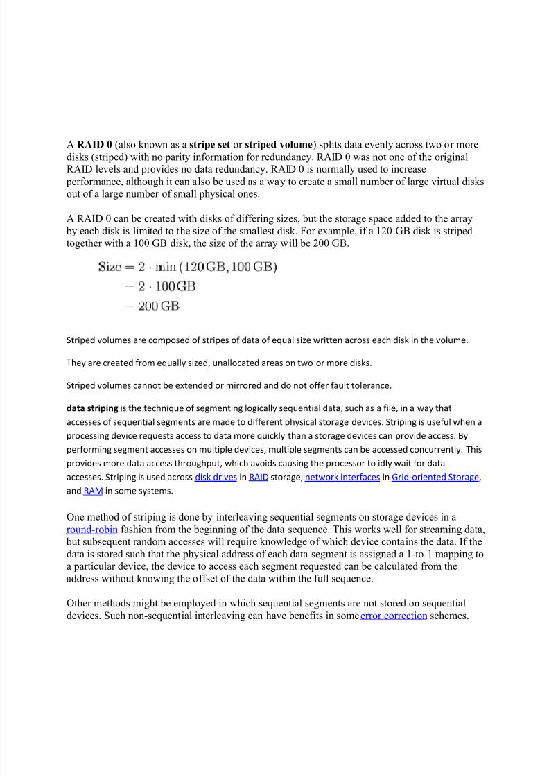
A RAID 0 can be created with disks of differing sizes, but the storage space added to the array
by each disk is limited to the size of the smallest disk. For example, if a 120 GB disk is stripedtogether with a 100 GB disk, the size of the array will be 200 GB.
Striped volumes are composed of stripes of data of equal size written across each disk in the volume.
They are created from equally sized, unallocated areas on two or more disks.
Striped volumes cannot be extended or mirrored and do not offer fault tolerance.
data striping is the technique of segmenting logically sequential data, such as a file, in a way thataccesses of sequential segments are made to different physical storage devices. Striping is useful when a
processing device requests access to data more quickly than a storage devices can provide access. By
performing segment accesses on multiple devices, multiple segments can be accessed concurrently. This
provides more data access throughput, which avoids causing the processor to idly wait for data
accesses. Striping is used across disk drives in RAID storage, network interfaces in Grid-oriented Storage,
and RAM in some systems.
One method of striping is done by interleaving sequential segments on storage devices in a
round-robin fashion from the beginning of the data sequence. This works well for streaming data,
but subsequent random accesses will require knowledge of which device contains the data. If thedata is stored such that the physical address of each data segment is assigned a 1-to-1 mapping toa particular device, the device to access each segment requested can be calculated from the
address without knowing the offset of the data within the full sequence.
Other methods might be employed in which sequential segments are not stored on sequential
devices. Such non-sequential interleaving can have benefits in some error correction schemes.

8/7/2019 Storage Backups
http://slidepdf.com/reader/full/storage-backups 4/23
Advantages of striping include performance and throughput. Sequential time interleaving of dataaccesses allows the lesser data access throughput of each storage devices to be cumulatively
multiplied by the number of storage devices employed. Increased throughput allows the data processing device to continue its work without interruption, and thereby finish its procedures
more quickly. This is manifested in improved performance of the data processing.
Because different segments of data are kept on different storage devices, the failure of one devicecauses the corruption of the full data sequence. In effect, the failure rate of the array of storage
devices is equal to the sum of the failure rate of each storage device. This disadvantage of striping can be overcome by the storage of redundant information, such as parity, for the purpose
of error correction. In such a system, the disadvantage is over come at the cost of requiring extrastorage.
Wide Striping occurs when chunks of data are spread across multiple arrays, possibly all the drives in the
system. Narrow Striping occurs when the chunks of data are spread across the drives in a single array.
Data striping is used in some modern databases, such as Sybase, and in certain RAID devices under
software or hardware control, such as IBM's RAMAC array subsystem. File systems of clusters also use
striping. Oracle Automatic Storage Management allows ASM files to be either coarse or fine striped.
Data striping can also be achieved with Linux's Logical Volume Management (LVM). The LVM system
allows for the adjustment of coarseness of the striping pattern. LVM tools will allow implementation of
data striping in conjunction with mirroring; however, LVM1 will not allow adding additional disks to a
striped Logical Volume (LV). This can be achieved with LVM2 using LVM2 format metadata.
R AID 0 failure rate
This section does not cite any references or sources.Please help improve this article by adding citations to reliable sources. Unsourced material may be
challenged and removed. (M arch 2010)
Although RAID 0 was not specified in the original RAID paper, an idealized implementation of
RAID 0 would split I/O operations into equal-sized blocks and spread them evenly across twodisks. RAID 0 implementations with more than two disks are also possible, though the group
reliability decreases with member size.
Reliability of a given RAID 0 set is equal to the average reliability of each disk divided by thenumber of disks in the set:

8/7/2019 Storage Backups
http://slidepdf.com/reader/full/storage-backups 5/23
That is, reliability (as measured by mean time to failure (MTTF) or mean time between failures (MTBF)) is roughly inversely proportional to the number of members ± so a set of two disks is
roughly half as reliable as a single disk. If there were a probability of 5% that the disk would failwithin three years, in a two disk array, that probability would be increased to
.
The reason for this is that the file system is distributed across all disks. When a drive fails the filesystem cannot cope with such a large loss of data and coherency since the data is "striped" across
all drives (the data cannot be recovered without the missing disk). Data can be recovered usingspecial tools, however, this data will be incomplete and most likely corrupt, and data recovery is
typically very costly and not guaranteed.
[edit] R AID 0 performance
While the block size can technically be as small as a byte, it is almost always a multiple of the
hard disk sector size of 512 bytes. This lets each drive seek independently when randomlyreading or writing data on the disk. How much the drives act independently depends on the
access pattern from the file system level. For reads and writes that are larger than the stripe size,such as copying files or video playback, the disks will be seeking to the same position on each
disk, so the seek time of the array will be the same as that of a single drive. For reads and writesthat are smaller than the stripe size, such as database access, the drives will be able to seek
independently. If the sectors accessed are spread evenly between the two drives, the apparentseek time of the array will be half that of a single drive (assuming the disks in the array have
identical access time characteristics). The transfer speed of the array will be the transfer speed of all the disks added together, limited only by the speed of the RAID controller. Note that these
performance scenarios are in the best case with optimal access patterns.
RAID 0 is useful for setups such as large read-only NFS server where mounting many disks istime-consuming or impossible and redundancy is irrelevant.
RAID 0 is also used in some gaming systems where performance is desired and data integrity is
not very important. However, real-world tests with games have shown that RAID-0 performancegains are minimal, although some desktop applications will benefit.[1][2] Another article
examined these claims and concludes: "Striping does not always increase performance (in certainsituations it will actually be slower than a non-RAID setup), but in most situations it will yield a
significant improvement in performance."[3]
[edit] R AID 1

8/7/2019 Storage Backups
http://slidepdf.com/reader/full/storage-backups 6/23
Diagram of a RAID 1 setup
A R AID 1 creates an exact copy (or mirror) of a set of data on two or more disks. This is useful
when read performance or reliability is more important than data storage capacity. Such an arraycan only be as big as the smallest member disk. A classic RAID 1 mirrored pair contains two
disks (see diagram), which increases reliability geometrically over a single disk. Since eachmember contains a complete copy of the data, and can be addressed independently, ordinary
wear-and-tear reliability is raised by the power of the number of self-contained copies.
[edit] R AID 1 failure rate
This section does not cite any references or sources.Please help improve this article by adding citations to reliable sources. Unsourced material may be
challenged and removed. (M arch 2010)
As a trivial example, consider a RAID 1 with two identical models of a disk drive with a 5%
probability that the disk would fail within three years. Provided that the failures are statistically
independent, then the probability of both disks failing during the three year lifetime is
.
Thus, the probability of losing all data is 0.25% over a three year period if nothing is done to the
array. If the first disk fails and is never replaced, then there is a 5% chance the data will be lost.
If only one of the disks fails, no data would be lost. As long as a failed disk is replaced before the
second disk fails, the data is safe.
However, since two identical disks are used and since their usage patterns are also identical, their failures cannot be assumed to be independent. Thus, the probability of losing all data, if the first
failed disk is not replaced, may be considerably higher than 5%.
As a practical matter, in a well-managed system the above is irrelevant because the failed harddrive will not be ignored but will be replaced. The reliability of the overall system is determined

8/7/2019 Storage Backups
http://slidepdf.com/reader/full/storage-backups 7/23
by the probability the remaining drive will continue to operate through the repair period, that isthe total time it takes to detect a failure, replace the failed hard drive, and for that drive to be
rebuilt. If, for example, it takes one hour to replace the failed drive, the overall system reliabilityis defined by the probability the remaining drive will operate for one hour without failure.
While RAID
1 can be an effective protection against physical disk failure, it does not provide protection against data corruption due to viruses, accidental file changes or deletions, or anyother data-specific changes. By design, any such changes will be instantly mirrored to every
drive in the array segment. A virus, for example, that damages data on one drive in a RAID 1array will damage the same data on all other drives in the array at the same time. For this reason
systems using RAID 1 to protect against physical drive failure should also have a traditional data backup process in place to allow data restoration to previous points in time. It would seem self-
evident that any system critical enough to require disk redundancy also needs the protection of reliable data backups.
[edit] R AID 1 performance
Since all the data exist in two or more copies, each with its own hardware, the read performance
can go up roughly as a linear multiple of the number of copies. That is, a RAID 1 array of twodrives can be reading in two different places at the same time, though not all implementations of
RAID 1 do this.[4]
To maximize performance benefits of RAID 1, independent disk controllersare recommended, one for each disk. Some refer to this practice as splitting or duplexing. When
reading, both disks can be accessed independently and requested sectors can be split evenly between the disks. For the usual mirror of two disks, this would, in theory, double the transfer
rate when reading. The apparent access time of the array would be half that of a single drive.Unlike RAID 0, this would be for all access patterns, as all the data are present on all the disks.
In reality, the need to move the drive heads to the next block (to skip blocks already read by the
other drives) can effectively mitigate speed advantages for sequential access. Read performancecan be further improved by adding drives to the mirror. Many older IDE RAID 1 controllers readonly from one disk in the pair, so their read performance is always that of a single disk. Some
older RAID 1 implementations would also read both disks simultaneously and compare the datato detect errors. The error detection and correction on modern disks makes this less useful in
environments requiring normal availability. When writing, the array performs like a single disk,as all mirrors must be written with the data. Note that these performance scenarios are in the best
case with optimal access patterns.
RAID 1 has many administrative advantages. For instance, in some environments, it is possible
to "split the mirror": declare one disk as inactive, do a backup of that disk, and then "rebuild" the
mirror. This is useful in situations where the file system must be constantly available. Thisrequires that the application supports recovery from the image of data on the disk at the point of the mirror split. This procedure is less critical in the presence of the "snapshot" feature of some
file systems, in which some space is reserved for changes, presenting a static point-in-time viewof the file system. Alternatively, a new disk can be substituted so that the inactive disk can be
kept in much the same way as traditional backup. To keep redundancy during the backup process, some controllers support adding a third disk to an active pair. After a rebuild to the third
disk completes, it is made inactive and backed up as described above.

8/7/2019 Storage Backups
http://slidepdf.com/reader/full/storage-backups 8/23
[edit] R AID 2
A R AID 2 stripes data at the bit (rather than block) level, and uses a Hamming code for error correction. The disks are synchronized by the controller to spin at the same angular orientation
(they reach Index at the same time). Extremely high data transfer rates are possible. This is the
only original level of RAID that is not currently used.[5][6]
The use of the Hamming(7,4) code (four data bits plus three parity bits) also permits using 7disks in RAID 2, with 4 being used for data storage and 3 being used for error correction.
RAID 2 is the only standard RAID level, other than some implementations of RAID 6, which
can automatically recover accurate data from single-bit corruption in data. Other RAID levelscan detect single-bit corruption in data, or can sometimes reconstruct missing data, but cannot
reliably resolve contradictions between parity bits and data bits without human intervention.
(Multiple-bit corruption is possible though extremely rare. RAID 2 can detect but not repair
double-bit corruption.)
All hard disks soon after implemented an error correction code that also used Hamming code, soRAID 2's error correction was now redundant and added unnecessary complexity. Like RAID 3,
this level quickly became useless and it is now obsolete. There are no commercial applications of RAID 2.[5][6]
[edit] R AID 3
Diagram of a RAID 3 setup of 6-byte blocks and two parity bytes, shown are two blocks of datain different colors.
A R AID 3 uses byte-level striping with a dedicated parity disk. RAID 3 is very rare in practice.
One of the side effects of RAID 3 is that it generally cannot service multiple requestssimultaneously. This comes about because any single block of data will, by definition, be spread
8/7/2019 Storage Backups
http://slidepdf.com/reader/full/storage-backups 9/23
across all members of the set and will reside in the same location. So, any I/O operation requiresactivity on every disk and usually requires synchronized spindles.
In our example, a request for block "A" consisting of bytes A1-A6 would require all three data
disks to seek to the beginning (A1) and reply with their contents. A simultaneous request for
block B would have to wait.
However, the performance characteristic of RAID 3 is very consistent, unlike higher RAID
levels,[clarification needed ] the size of a stripe is less than the size of a sector or OS block so that, for both reading and writing, the entire stripe is accessed every time. The performance of the array is
therefore identical to the performance of one disk in the array except for the transfer rate, whichis multiplied by the number of data drives (i.e., less parity drives).
This makes it best for applications that demand the highest transfer rates in long sequential readsand writes, for example uncompressed video editing. Applications that make small reads and
writes from random places over the disk will get the worst performance out of this level.[6]
The requirement that all disks spin synchronously, aka in lockstep, added design considerationsto a level that didn't give significant advantages over other RAID levels, so it quickly became
useless and is now obsolete.[5]
Both RAID 3 and RAID 4 were quickly replaced by RAID 5.[7]
However, this level has commercial vendors making implementations of it. It's usually
implemented in hardware, and the performance issues are addressed by using large disks.[6]
[edit] R AID 4
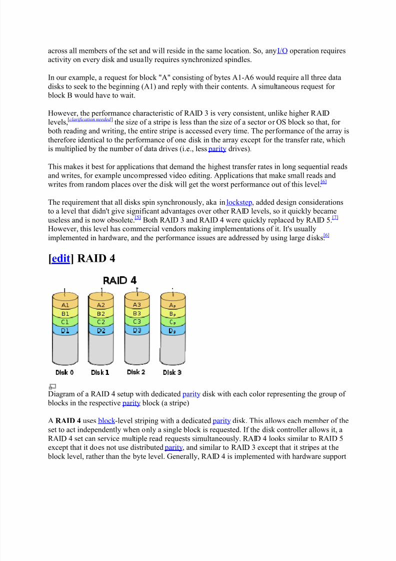
Diagram of a RAID 4 setup with dedicated parity disk with each color representing the group of blocks in the respective parity block (a stripe)
A R AID 4 uses block -level striping with a dedicated parity disk. This allows each member of the
set to act independently when only a single block is requested. If the disk controller allows it, a
RAID 4 set can service multiple read requests simultaneously. RAID 4 looks similar to RAID 5except that it does not use distributed parity, and similar to RAID 3 except that it stripes at the
block level, rather than the byte level. Generally, RAID 4 is implemented with hardware support

8/7/2019 Storage Backups
http://slidepdf.com/reader/full/storage-backups 10/23
for parity calculations, and a minimum of 3 disks is required for a complete RAID 4configuration.
In the example on the right, a read request for block A1 would be serviced by disk 0. A
simultaneous read request for block B1 would have to wait, but a read request for B2 could be
serviced concurrently by disk 1.
For writing, the parity disk becomes a bottleneck, as simultaneous writes to A1 and B2 would, in
addition to the writes to their respective drives, also both need to write to the parity drive. In thisway RAID 4 places a very high load on the parity drive in an array.
The performance of RAID 4 in this configuration can be very poor, but unlike RAID 3 it doesnot need synchronized spindles. However, if RAID 4 is implemented on synchronized drives and
the size of a stripe is reduced below the OS block size a RAID 4 array then has the same performance pattern as a RAID 3 array.
Currently, RAID
4 is only implemented at the enterprise level by one single company, NetApp,who solved the performance problems discussed above with their proprietary Write AnywhereFile Layout.
[citation needed ]
Both RAID 3 and RAID 4 were quickly replaced by RAID 5.[7]
[edit] R AID 5
Diagram of a RAID 5 setup with distributed parity with each color representing the group of blocks in the respective parity block (a stripe). This diagram shows left asymmetric algorithm
A R AID 5 uses block -level striping with parity data distributed across all member disks. RAID 5
has achieved popularity because of its low cost of redundancy. This can be seen by comparing
the number of drives needed to achieve a given capacity. RAID 1 or RAID 1+0, which yield
redundancy, give only s / n storage capacity, where s is the sum of the capacities of n drives

8/7/2019 Storage Backups
http://slidepdf.com/reader/full/storage-backups 11/23
used. In RAID 5, the yield is where S min is the size of the smallest disk in the
array. As an example, four 1 TB drives can be made into a 2 TB redundant array under RAID 1or RAID 1+0, but the same four drives can be used to build a 3 TB array under RAID 5.
Although RAID 5 may be implemented in a disk controller, some have hardware support for parity calculations (hardware RAID cards with onboard processors) while some use the main
system processor (a form of software RAID in vendor drivers for inexpensive controllers). Manyoperating systems also provide software RAID support independently of the disk controller, such
as Windows Dynamic Disks, Linux md RAID, or RAID-Z. A minimum of three disks is requiredfor a complete RAID 5 configuration. In some implementations a degraded RAID 5 disk set can
be made (three disk set of which only two are online), while mdadm supports a fully-functional(non-degraded) RAID 5 setup with two disks - which function as a slow RAID-1, but can be
expanded with further volumes.
In the example, a read request for block A1 would be serviced by disk 0. A simultaneous read
request for block B1 would have to wait, but a read request for B2 could be servicedconcurrently by disk 1.
[edit] R AID 5 parity handling
A concurrent series of blocks (one on each of the disks in an array) is collectively called a stripe.
If another block, or some portion thereof, is written on that same stripe, the parity block, or some portion thereof, is recalculated and rewritten. For small writes, this requires:
y Read the old data block
y Read the old parity block y Compare the old data block with the write request. For each bit that has flipped (changed
from 0 to 1, or from 1 to 0) in the data block, flip the corresponding bit in the parity block y Write the new data block y Write the new parity block
The disk used for the parity block is staggered from one stripe to the next, hence the term
distributed parity blocks. RAID 5 writes are expensive in terms of disk operations and traffic between the disks and the controller.
The parity blocks are not read on data reads, since this would add unnecessary overhead and
would diminish performance. The parity blocks are read, however, when a read of blocks in thestripe fails due to failure of any one of the disks, and the parity block in the stripe are used to
reconstruct the errant sector. The CRC error is thus hidden from the main computer. Likewise,
should a disk fail in the array, the parity blocks from the surviving disks are combinedmathematically with the data blocks from the surviving disks to reconstruct the data from thefailed drive on-the-fly.
This is sometimes called InterimData Recovery Mode. The computer knows that a disk drive
has failed, but this is only so that the operating system can notify the administrator that a driveneeds replacement; applications running on the computer are unaware of the failure. Reading and
writing to the drive array continues seamlessly, though with some performance degradation.
8/7/2019 Storage Backups
http://slidepdf.com/reader/full/storage-backups 12/23
[edit] R AID 5 disk failure rate
The maximum number of drives in a RAID 5 redundancy group is theoretically unlimited. The
tradeoffs of larger redundancy groups are greater probability of a simultaneous double disk failure, the increased time to rebuild a redundancy group, and the greater probability of
encountering an unrecoverable sector during RAID reconstruction. As the number of disks in aRAID 5 group increases, the mean time between failures (MTBF, the reciprocal of the failurerate) can become lower than that of a single disk. This happens when the likelihood of a second
disk's failing out of N í 1 dependent disks, within the time it takes to detect, replace and
recreate a first failed disk, becomes larger than the likelihood of a single disk's failing.
Solid-state drives (SSDs) may present a revolutionary instead of evolutionary way of dealing
with increasing RAID-5 rebuild limitations. With encouragement from many flash-SSD manufacturers, JEDEC is preparing to set standards in 2009 for measuring UBER (uncorrectable
bit error rates) and "raw" bit error rates (error rates before ECC, error correction code).[8]
Buteven the economy-class Intel X25-M SSD claims an unrecoverable error rate of 1 sector in 10
15
bits and an MTBF of two million hours.[9]
Ironically, the much-faster throughput of SSDs (STECclaims its enterprise-class Zeus SSDs exceed 200 times the transactional performance of today's
15k-RPM, enterprise-class HDDs)[10]
suggests that a similar error rate (1 in 1015
) will result atwo-magnitude shortening of MTBF.
In the event of a system failure while there are active writes, the parity of a stripe may become
inconsistent with the data. If this is not detected and repaired before a disk or block fails, dataloss may ensue as incorrect parity will be used to reconstruct the missing block in that stripe.
This potential vulnerability is sometimes known as the write hole. Battery-backed cache andsimilar techniques are commonly used to reduce the window of opportunity for this to occur. The
same issue occurs for RAID-6.
[edit] R AID 5 performance
RAID 5 implementations suffer from poor performance when faced with a workload which
includes many writes which are smaller than the capacity of a single stripe. This is because parity must be updated on each write, requiring read-modify-write sequences for both the data block
and the parity block. More complex implementations may include a non-volatile write back cache to reduce the performance impact of incremental parity updates. Large writes, spanning an
entire stripe width, can however be done without read-modify-write cycles for each data + parity block, by simply overwriting the parity block with the computed parity since the new data for
each data block in the stripe is known in its entirety at the time of the write. This is sometimes
called a full stripe write.
Random write performance is poor, especially at high concurrency levels common in large multi-
user databases. The read-modify-write cycle requirement of RAID 5's parity implementation penalizes random writes by as much as an order of magnitude compared to RAID 0.[11]
Performance problems can be so severe that some database experts have formed a group calledBAARF ² the Battle Against Any Raid Five.
[12]

8/7/2019 Storage Backups
http://slidepdf.com/reader/full/storage-backups 13/23
The read performance of RAID 5 is almost as good as RAID 0 for the same number of disks.Except for the parity blocks, the distribution of data over the drives follows the same pattern as
RAID 0. The reason RAID 5 is slightly slower is that the disks must skip over the parity blocks.
[edit] R AID 5 latency
When a disk record is randomly accessed there is a delay as the disk rotates sufficiently for thedata to come under the head for processing. This delay is called Latency. On average, a single
disk will need to rotate 1/2 revolution. Thus, for a 7200 RPM disk the average latency is 4.2milliseconds. In RAID 5 arrays all the disks must be accessed so the latency can become a
significant factor. In a RAID 5 array, with n randomly oriented disks, the average latency becomes 1-2
-nrevolutions. In order to mitigate this problem well designed RAID systems will
synchronize the angular orientation of their disks. In this case the random nature of the angular displacements goes away, the average latency returns to 1/2 revolution, and a savings of up to
50% in latency is achieved. Since Solid State Disks do not rotate their Latency is always 0.
Effect of Angular Synchronization
Number of
Disks
AverageRandomly
OrientedLatency
Percent savingusing Angular
Synchronization
1 0.500 0%
2 0.750 33%
3 0.875 43%
4 0.938 47%
5 0.969 48%
6 0.984 49%
7 0.992 50%
8 0.996 50%
[edit] R AID 5 usable size
Parity data uses up the capacity of one drive in the array (this can be seen by comparing it with
RAID 4: RAID 5 distributes the parity data across the disks, while RAID 4 centralizes it on onedisk, but the amount of parity data is the same). If the drives vary in capacity, the smallest of
them sets the limit. Therefore, the usable capacity of a RAID 5 array is , where
N is the total number of drives in the array and S min is the capacity of the smallest drive in the
array.
The number of hard disks that can belong to a single array is limited only by the capacity of thestorage controller in hardware implementations, or by the OS in software RAID. One caveat is
that unlike RAID 1, as the number of disks in an array increases, the chance of data loss due to
8/7/2019 Storage Backups
http://slidepdf.com/reader/full/storage-backups 14/23
multiple drive failures is increased. This is because there is a reduced ratio of "losable" drives(the number of drives which may fail before data is lost) to total drives.
[citation needed ]
[edit] R AID 6
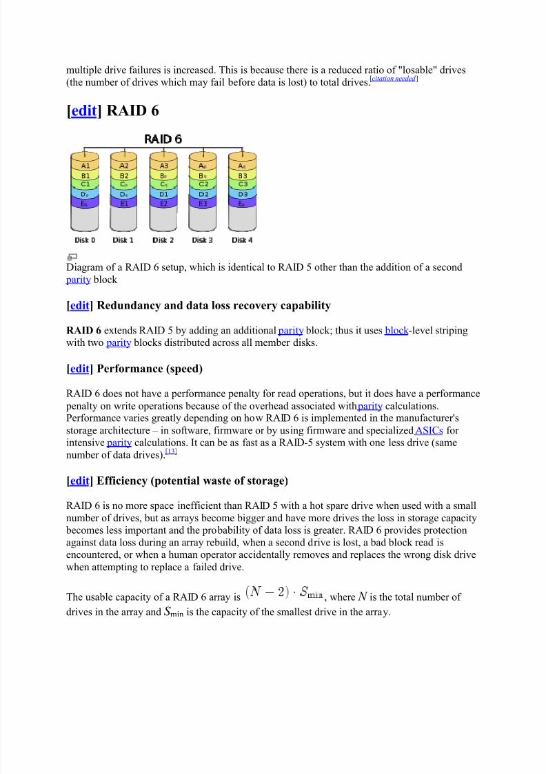
Diagram of a RAI
D6 setup, which is identical to RAI
D5 other than the addition of a second parity block
[edit] R edundancy and data loss recovery capability
R AID 6 extends RAID 5 by adding an additional parity block; thus it uses block -level stripingwith two parity blocks distributed across all member disks.
[edit] Performance (speed)
RAID 6 does not have a performance penalty for read operations, but it does have a performance
penalty on write operations because of the overhead associated with parity calculations.Performance varies greatly depending on how RAID 6 is implemented in the manufacturer's
storage architecture ± in software, firmware or by using firmware and specialized ASICs for intensive parity calculations. It can be as fast as a RAID-5 system with one less drive (same
number of data drives).[13]
[edit] Efficiency (potential waste of storage)
RAID 6 is no more space inefficient than RAID 5 with a hot spare drive when used with a small
number of drives, but as arrays become bigger and have more drives the loss in storage capacity becomes less important and the probability of data loss is greater. RAID 6 provides protection
against data loss during an array rebuild, when a second drive is lost, a bad block read isencountered, or when a human operator accidentally removes and replaces the wrong disk drive
when attempting to replace a failed drive.
The usable capacity of a RAID 6 array is , where N is the total number of
drives in the array and S min is the capacity of the smallest drive in the array.

8/7/2019 Storage Backups
http://slidepdf.com/reader/full/storage-backups 15/23
[edit] Implementation
According to the Storage Networking Industry Association (SNIA), the definition of RAID 6 is:
"Any form of RAID that can continue to execute read and write requests to all of a RAID array'svirtual disks in the presence of any two concurrent disk failures. Several methods, including dual
check data computations ( parity and Reed-Solomon), orthogonal dual parity check data anddiagonal parity, have been used to implement RAID Level 6."
[14]
[edit] Computing parity
Two different syndromes need to be computed in order to allow the loss of any two drives. Oneof them, P can be the simple XOR of the data across the stripes, as with RAID 5. A second,
independent syndrome is more complicated and requires the assistance of field theory.
To deal with this, the Galois field GF (m) is introduced with m = 2k , where
for a suitable irreducible polynomial p( x) of degree k . A chunk of
data can be written as d k í 1d k í 2...d 0 in base 2 where each d i is either 0 or 1. This is chosen to
correspond with the element d k í 1 xk í 1 + d k í 2 x
k í 2 + ... + d 1 x + d 0 in the Galois field. Let
correspond to the stripes of data across hard drives encoded as field
elements in this manner (in practice they would probably be broken into byte-sized chunks). If g is some generator of the field and denotes addition in the field while concatenation denotes
multiplication, then and may be computed as follows (n denotes the number of data disks):
F or a computer scientist, a good way to think about this is that is a bitwise XOR operator and
g i is the action of a linear feedback shift register on a chunk of data. Thus, in the formula
above,[15]
the calculation of P is just the XOR of each stripe. This is because addition in anycharacteristic two finite field reduces to the XOR operation. The computation of Q is the XOR of
a shifted version of each stripe.
Mathematically, the generator is an element of the field such that g i is different for each
nonnegative i satisfying i < n.
If one data drive is lost, the data can be recomputed from P just like with RAID 5. If two datadrives are lost or the drive containing P is lost the data can be recovered from P and Q using a
more complex process. Working out the details is not hard with field theory. Suppose that Di and
D j are the lost values with . Using the other values of D, constants A and B may be found
so that and . Multiplying both sides of the latter equation

8/7/2019 Storage Backups
http://slidepdf.com/reader/full/storage-backups 16/23
by g n í iand adding to the former equation yields and thus
a solution for D j which may be used to compute Di.
The computation of Q is CPU intensive compared to the simplicity of P. Thus, a RAID 6implemented in software will have a more significant effect on system performance, and a
hardware solution will be more complex.
Small Computer System Interface (SCSI, /skzi/ SKUHZ -ee)[1]
is a set of standards for physically connecting and transferring data between computers and peripheral devices. The SCSI
standards define commands, protocols, and electrical and optical interfaces. SCSI is mostcommonly used for hard disks and tape drives, but it can connect a wide range of other devices,
including scanners and CD drives. The SCSI standard defines command sets for specific peripheral device types; the presence of "unknown" as one of these types means that in theory itcan be used as an interface to almost any device, but the standard is highly pragmatic and
addressed toward commercial requirements.
SCSI is an intelligent, peripheral, buffered, peer to peer interface. It hides the complexity of physical format. Every device attaches to the SCSI bus in a similar manner. Up to 8 or 16
devices can be attached to a single bus. There can be any number of hosts and peripheral devices but there should be at least one host. SCSI uses hand shake signals between devices, SCSI-1,
SCSI-2 have the option of parity error checking. Starting with SCSI-U160 (part of SCSI-3) allcommands and data are error checked by a CRC32 checksum. The SCSI protocol defines
communication from host to host, host to a peripheral device, peripheral device to a peripheraldevice. However most peripheral devices are exclusively SCSI targets, incapable of acting as
SCSI initiators ²unable to initiate SCSI transactions themselves. Therefore peripheral-to-
peripheral communications are uncommon, but possible in most SCSI applications. The SymbiosLogic 53C810 chip is an example of a PCI host interface that can act as a SCSI target.
A storage area network (SAN) is a dedicated storage network that provides access to
consolidated, block level storage. SANs primarily are used to make storage devices (such as disk
arrays, tape libraries, and optical jukeboxes) accessible to servers so that the devices appear aslocally attached to the operating system. A SAN typically has its own network of storage devicesthat are generally not accessible through the regular network by regular devices. The cost and
complexity of SANs dropped in the early 2000s, allowing wider adoption across both enterpriseand small to medium sized business environments.

8/7/2019 Storage Backups
http://slidepdf.com/reader/full/storage-backups 17/23
A SAN alone does not provide the "file" abstraction, only block-level operations. However, filesystems built on top of SANs do provide this abstraction, and are known as SAN filesystems or
shared disk file systems.
Storage sharing
Organization
Historically, data centers first created "islands" of SCSI disk arrays as direct-attached storage (DAS), each dedicated to an application, and visible as a number of "virtual hard drives" (i.e.
LUNs). Essentially, a SAN consolidates such storage islands together using a high-speednetwork.
O perating systems maintain their own file systems on them on dedicated, non-shared LUNs, as
though they were local to themselves. If multiple systems were simply to attempt to share a
LUN, these would interfere with each other and quickly corrupt the data. Any planned sharing of data on different computers within a LUN requires advanced solutions, such as SAN file systems or clustered computing.
Despite such issues, SANs help to increase storage capacity utilization, since multiple serversconsolidate their private storage space onto the disk arrays.
Common uses of a SAN include provision of transactionally accessed data that require high-
speed block-level access to the hard drives such as email servers, databases, and high usage fileservers.
[edit] SAN and NAS
Network-attached storage (NAS), in contrast to SAN, uses file-based protocols such as NFS or
SMB/CIFS where it is clear that the storage is remote, and computers request a portion of anabstract file rather than a disk block. Recently,
[when?]the introduction of NAS heads, also called
NAS gateways, has allowed easy conversion of SAN storage to NAS.
[edit] SAN-NAS hybrid

8/7/2019 Storage Backups
http://slidepdf.com/reader/full/storage-backups 18/23
Hybrid using DAS, NAS and SAN technologies.
Despite the differences between SAN and NAS, it is possible to create solutions that include both
technologies, as shown in the diagram.
[edit] Benefits
Sharing storage usually simplifies storage administration and adds flexibility since cables and
storage devices do not have to be physically moved to shift storage from one server to another.
Other benefits include the ability to allow servers to boot from the SAN itself. This allows for aquick and easy replacement of faulty servers since the SAN can be reconfigured so that a
replacement server can use the LUN of the faulty server. This process can take as little as half anhour and is a relatively new idea
[when?]being pioneered in newer data centers. There are a number
of emerging products designed to facilitate and speed this up still further. While this area of technology is still new many view it as being the future of the enterprise datacenter.
[1]
SANs also tend to enable more effective disaster recovery processes. A SAN could span a distantlocation containing a secondary storage array. This enables storage replication either
implemented by disk array controllers, by server software, or by specialized SAN devices. SinceIP WANs are often the least costly method of long-distance transport, the Fibre Channel over IP
(FCIP) and iSCSI protocols have been developed to allow SAN extension over IP networks. Thetraditional physical SCSI layer could only support a few meters of distance - not nearly enough
to ensure business continuance in a disaster.
The economic consolidation of disk arrays has accelerated the advancement of several featuresincluding I/O caching, snapshotting, and volume cloning (Business Continuance Volumes or
BCVs).
SAN infrastructure

8/7/2019 Storage Backups
http://slidepdf.com/reader/full/storage-backups 19/23
Qlogic SAN-switch with optical Fibre Channel connectors installed.
SANs often utilize a Fibre Channel fabric topology - an infrastructure specially designed to
handle storage communications. It provides faster and more reliable access than higher-level protocols used in NAS. A fabric is similar in concept to a network segment in a local area
network. A typical Fibre Channel SAN fabric is made up of a number of Fibre Channel switches.
Today, all major SAN equipment vendors also offer some form of Fibre Channel routingsolution, and these bring substantial scalability benefits to the SAN architecture by allowing datato cross between different fabrics without merging them. These offerings use proprietary
protocol elements, and the top-level architectures being promoted are radically different. Theyoften enable mapping Fibre Channel traffic over IP or over SO NET/SDH.
[edit] Compatibility
One of the early problems with Fibre Channel SANs was that the switches and other hardwarefrom different manufacturers were not entirely compatible. Although the basic storage protocols
FCP were always quite standard, some of the higher-level functions did not interoperate well.
Similarly, many host operating systems would react badly to other operating systems sharing thesame fabric. Many solutions were pushed to the market before standards were finalised andvendors have since innovated around the standards
[citation needed ].
[edit] SANs in media and entertainment
Video editing workgroups require very high data transfer rates. Outside of the enterprise market,this is one area that greatly benefits from SANs.
Per-node bandwidth usage control, sometimes referred to as Quality of Service (QoS), is
especially important in video workgroups as it ensures fair and prioritized bandwidth usageacross the network, if there is insufficient open bandwidth available. Avid Unity, Apple's Xsan and Tiger Technology MetaSAN are specifically designed for video networks and offer this
functionality.
[edit] Storage virtualization

8/7/2019 Storage Backups
http://slidepdf.com/reader/full/storage-backups 20/23
Storage virtualization refers to the process of completely abstracting logical storage from physical storage. The physical storage resources are aggregated into storage pools, from which
the logical storage is created. It presents to the user a logical space for data storage andtransparently handles the process of mapping it to the actual physical location. This is
implemented in modern disk arrays, using vendor proprietary solutions. However, the goal is to
virtualize multiple disk arrays from different vendors, scattered over the network, into a singlemonolithic storage device, which can be managed uniformly.
In computer storage, a logical unit number or LUN is a number used to identify a logical unit,which is a device addressed by the SCSI protocol or similar protocols such as Fibre Channel or
iSCSI. A LUN may be used with any device which supports read/write operations, such as a tapedrive, but is most often used to refer to a logical disk as created on a SAN. Though not
technically correct, the term "LUN" is often also used to refer to the drive itself.[1]
To provide a practical example, a typical disk array has multiple physical SCSI ports, each withone SCSI target address assigned. Then the disk array is formatted as a RAID and then this
RAID
is partitioned into several separated storage volumes. To represent each volume, a SCSItarget is configured to provide a logical unit. Each SCSI target may provide multiple logical units
and thus represent multiple volumes, but this does not mean that those volumes are concatenated.The computer that accesses a volume on the disk array identifies which volume to read or write
with the LUN of the associated logical unit.
Another example is a single disk drive with one physical SCSI port. It usually provides just a
single target, which in turn usually provides just a single logical unit whose LUN is zero. Thislogical unit represents the entire storage of the disk drive.
How to select a LUN: In the earliest versions of SCSI, an initiator delivers a CommandData
Block (CD
B) to a target (physical unit) and within the CD
B is a 3-bit LUN field to identify thelogical unit within the target. In current SCSI, the initiator delivers the CDB to a particular
logical unit, so the LUN appears in the transport layer data structures and not in the CDB.
LUN vs. SCSI Device ID: The LUN is not the only way to identify a logical unit. There is alsothe SCSI Device ID, which identifies a logical unit uniquely in the world. Labels or serial
numbers stored in a logical unit's storage volume often serve to identify the logical unit.However, the LUN is the only way for an initiator to address a command to a particular logical
unit, so initiators often create, via a discovery process, a mapping table of LUN to other identifiers.
Context sensitive: The LUN identifies a logical unit only within the context of a particular initiator. So two computers that access the same disk volume may know it by different LUNs.
LUN 0: There is one LUN which is required to exist in every target: zero. The logical unit with
LUN zero is special in that it must implement a few specific commands, most notably ReportLUNs, which is how an initiator can find out all the other LUNs in the target. But LUN zero
need not provide any other services, such as a storage volume.

8/7/2019 Storage Backups
http://slidepdf.com/reader/full/storage-backups 21/23
Many SCSI targets contain only one logical unit (so its LUN is necessarily zero). Others have asmall number of logical units that correspond to separate physical devices and have fixed LUNs.
A large storage system may have up to thousands of logical units, defined logically, byadministrative command, and the administrator may choose the LUN or the system may choose
it.
In Information Technology, a backup or the process of backing up refers to making copies of data so that these additional copies may be used to restore the original after a data loss event.
The verb form is back up in two words, whereas the noun is backup (often used like an adjectivein compound nouns).[1]
Backups have two distinct purposes. The primary purpose is to recover data as a reaction to data
loss, be it by data deletion or corrupted data. Data loss is a very common experience of computer users. 67% of internet users have suffered serious data loss.
[2]The secondary purpose of backups
is to recover data from a historical period of time within the constraints of a user-defined dataretention policy, typically configured within a backup application for how long copies of data are
required. Though backups popularly represent a simple form of disaster recovery, and should be part of a disaster recovery plan, by themselves, backups should not alone be considered disaster
recovery. [3] Not all backup systems and/or backup applications are able to reconstitute acomputer system, or in turn other complex configurations such as a computer cluster , active
directory servers, or a database server , by restoring only data from a backup.
Since a backup system contains at least one copy of all data worth saving, the data storage
requirements are considerable. Organizing this storage space and managing the backup process isa complicated undertaking. A data repository model can be used to provide structure to the
storage. In the modern era of computing there are many different types of data storage devices that are useful for making backups. There are also many different ways in which these devices
can be arranged to provide geographic redundancy, data security, and portability.
Before data is sent to its storage location, it is selected, extracted, and manipulated. Manydifferent techniques have been developed to optimize the backup procedure. These include
optimizations for dealing with open files and live data sources as well as compression,encryption, and de-duplication, among others. Many organizations and individuals try to have
confidence that the process is working as expected and work to define measurements andvalidation techniques. It is also important to recognize the limitations and human factors
involved in any backup scheme.
An incremental backup preserves data by creating multiple copies that are based on thedifferences in those data: a successive copy of the data contains only that portion which has
changed since the preceding copy has been created.
Incremental
The most basic form of incremental backup involves only those files that have changed since the
last backup. Since changes are typically slow, incremental backup is much smaller and quicker than a full backup. For instance, following a full backup on Friday, a Monday backup will

8/7/2019 Storage Backups
http://slidepdf.com/reader/full/storage-backups 22/23
contain only those files that changed since Friday. A Tuesday backup will contains only thosefiles that changed since Monday, and so on. A full restoration of data will naturally be slower,
since all increments must be restored. Should any one of the copies created fail, including thefirst (full), restoration will be incomplete.
An example of a typical incremental backup command in MS-DO
S would be:
xcopy c:\source\*.* d:\destination\*.* /s /m
A Unix example would be:
rsync -e ssh -va --link-dest=$dst/hourly.1 $remoteserver:$remotepath
$dst/hourly.0
The use of rsync's --link-dest option is what makes this command an example of incremental backup.
[edit] Differential
A cumulative backup of all changes made since the last full or normal backup, i.e., the
differences since the last full backup. The advantage to this is the quicker recovery time,requiring only a full backup and the last differential backup to restore the system. The
disadvantage is that for each day elapsed since the last full backup, more data needs to be backedup, especially if a significant proportion of the data has changed.
[edit] Multilevel incremental
A more sophisticated incremental backup scheme involves multiple numbered backup levels. A
full backup is level 0. A level n backup will back up everything that has changed since the mostrecent level n-1 backup. Suppose for instance that a level 0 backup was taken on a Sunday. A
level 1 backup taken on Monday would include only changes made since Sunday. A level 2 backup taken on Tuesday would include only changes made since Monday. A level 3 backup
taken on Wednesday would include only changes made since Tuesday. If a level 2 backup wastaken on Thursday, it would include all changes made since M onday because Monday was the
most recent level n-1 backup.
[edit] R everse incremental
An incremental backup of the changes made between two instances of a mirror is called a reverse
incremental. By applying a reverse incremental to a mirror, the result will be a previous versionof the mirror.
[edit] Synthetic full backup
[edit] Incrementals forever

8/7/2019 Storage Backups
http://slidepdf.com/reader/full/storage-backups 23/23
This style is similar to the Synthetic backup concept. After an initial full backup, only theincremental backups are sent to a centralized backup server. This server keeps track of all the
incrementals and sends the proper data back to the server during restores. This can beimplemented by sending each incremental directly to tape as it is taken and then refactoring the
tapes as necessary. If enough disk space is available, an online mirror can be maintained along
with previous incremental changes so that the current or older versions of the systems being backed up can be restored.This is a suitable method in case of banking systems.
[edit] Block level incremental
This method backs up only the blocks within the file that changed. This requires a higher level of integration between the sender and receiver.
[edit] Byte level incremental or differential
These backup technologies are similar to the "block level incremental" backup method; however,
the byte (or binary) incremental or differential backup method is based on a binary variation of the files compared to the previous backup: while the block-based technologies work with heavy
changing units (blocks of 8K, 4K or 1K), the byte-based technologies work with the minimumunit, saving space when reflecting a change on a file. Another important difference is that they
work independently on the file system. At the moment, these are the technologies that achievethe highest relative compression of the data, turning into a great advantage for the security copies
carried out through the Internet.
[edit] Usage inconsistency
While the terms above are in very wide use, some backup vendors reverse the meaning of
"incremental" and "differential" although using these terms incorrectly could lead to botched backup jobs and loss of data. One case for example is Microsoft with NtBackup.exe.
[1]However,
no other such vendor is known today. On the other hand, it is technically accurate to refer to adifferential backup as a cumulative incremental backup but this use is discouraged as it isunnecessarily confusing. Additionally, while it is technically accurate to refer to an incremental
backup as a differential incremental backup, this use is also discouraged and unnecessarilyconfusing.