stm32h7 dual-core safety manual - user manual
TRANSCRIPT

IntroductionThis document must be read along with the technical documentation such as reference manual(s) and datasheets for theSTM32H7 dual-core microcontrollers, available on www.st.com.
It describes how to use the devices in the context of a safety-related system, specifying the user's responsibilities for installationand operation in order to reach the targeted safety integrity level. It also pertains to the X-CUBE-STL software product.
It provides the essential information pertaining to the applicable functional safety standards, which allows system designers toavoid going into unnecessary details.
The document is written in compliance with IEC 61508.
The safety analysis in this manual takes into account the device variation in terms of memory size, available peripherals, andpackage.
This manual addresses the STM32H7 dual-core microcontrollers (named as STM32H7 dual core), that include two CPU cores,the Arm® Cortex®-M7 and Cortex®-M4.
STM32H7 dual-core safety manual
UM2840
User manual
UM2840 - Rev 1 - July 2021For further information contact your local STMicroelectronics sales office.
www.st.com
1 About this document
1.1 Purpose and scopeThis document describes how to use Arm® Cortex®-M7-based STM32H7 dual-core microcontroller unit (MCU)devices (further also referred to as Device(s)) in the context of a safety‑related system, specifying the user'sresponsibilities for installation and operation, in order to reach the desired safety integrity level.It is useful to system designers willing to evaluate the safety of their solution embedding one or more Device(s).For terms used, refer to the glossary at the end of the document.Note that this manual addresses the STM32H7 dual-core microcontrollers, that are devices with two CPU cores,the Arm® Cortex®-M7 and Cortex®-M4.
Note: Arm is a registered trademark of Arm Limited (or its subsidiaries) in the US and/or elsewhere.
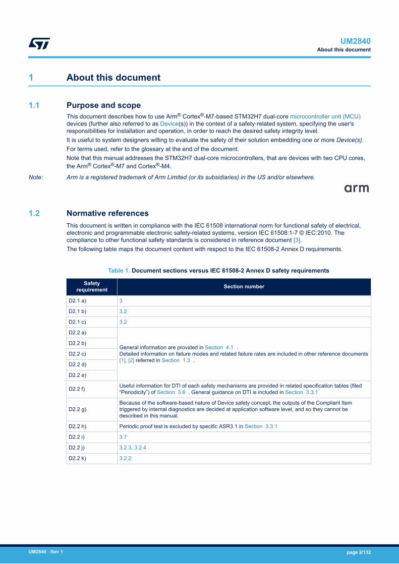
1.2 Normative referencesThis document is written in compliance with the IEC 61508 international norm for functional safety of electrical,electronic and programmable electronic safety-related systems, version IEC 61508:1-7 © IEC:2010. Thecompliance to other functional safety standards is considered in reference document [3].The following table maps the document content with respect to the IEC 61508-2 Annex D requirements.
Table 1. Document sections versus IEC 61508-2 Annex D safety requirements
Safetyrequirement Section number
D2.1 a) 3
D2.1 b) 3.2
D2.1 c) 3.2
D2.2 a)
General information are provided in Section 4.1 .Detailed information on failure modes and related failure rates are included in other reference documents[1], [2] referred in Section 1.3 .
D2.2 b)
D2.2 c)
D2.2 d)
D2.2 e)
D2.2 f) Useful information for DTI of each safety mechanisms are provided in related specification tables (filed“Periodicity”) of Section 3.6 . General guidance on DTI is included in Section 3.3.1
D2.2 g)Because of the software-based nature of Device safety concept, the outputs of the Compliant Itemtriggered by internal diagnostics are decided at application software level, and so they cannot bedescribed in this manual.
D2.2 h) Periodic proof test is excluded by specific ASR3.1 in Section 3.3.1
D2.2 i) 3.7
D2.2 j) 3.2.3, 3.2.4
D2.2 k) 3.2.2
UM2840About this document
UM2840 - Rev 1 page 2/132
1.3 Reference documents
[1] AN5631, Results of FMEA on STM32H7 dual-core microcontrollers
[2] AN5596, Results of FMEDA on STM32H7 dual-core microcontrollers
[3] AN5689, Adapting the X-CUBE-STL functional safety package for STM32 (IEC 61508 compliant) to other safetystandards
UM2840Reference documents
UM2840 - Rev 1 page 3/132
2 Device development process
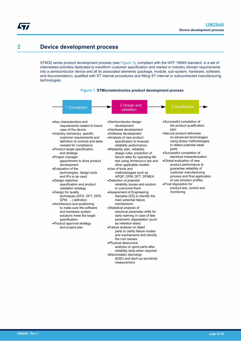
STM32 series product development process (see Figure 1), compliant with the IATF 16949 standard, is a set ofinterrelated activities dedicated to transform customer specification and market or industry domain requirementsinto a semiconductor device and all its associated elements (package, module, sub-system, hardware, software,and documentation), qualified with ST internal procedures and fitting ST internal or subcontracted manufacturingtechnologies.
Figure 1. STMicroelectronics product development process
·Key characteristics and requirements related to future uses of the device
·Industry domain(s), specific customer requirements and definition of controls and tests needed for compliance
·Product target specification and strategy
·Project manager appointment to drive product development
·Evaluation of the technologies, design tools and IPs to be used
·Design objective specification and product validation strategy
·Design for quality techniques (DFD, DFT, DFR, DFM, …) definition
·Architecture and positioning to make sure the software and hardware system solutions meet the target specification
·Product approval strategy and project plan
·Semiconductor design development
·Hardware development·Software development·Analysis of new product
specification to forecast reliability performance
·Reliability plan, reliability design rules, prediction of failure rates for operating life test using Arrhenius’s law and other applicable models
·Use of tools and methodologies such as APQP, DFM, DFT, DFMEA
·Detection of potential reliability issues and solution to overcome them
·Assessment of Engineering Samples (ES) to identify the main potential failure mechanisms
·Statistical analysis of electrical parameter drifts for early warning in case of fast parametric degradation (such as retention tests)
·Failure analysis on failed parts to clarify failure modes and mechanisms and identify the root causes
·Physical destructive analysis on good parts after reliability tests when required
·Electrostatic discharge (ESD) and latch-up sensitivity measurement
·Successful completion of the product qualification plan
·Secure product deliveries on advanced technologies using stress methodologies to detect potential weak parts
·Successful completion of electrical characterization
·Global evaluation of new product performance to guarantee reliability of customer manufacturing process and final application of use (mission profile)
·Final disposition for product test, control and monitoring
1 Conception 3 Qualification2 Design and validation
UM2840Device development process
UM2840 - Rev 1 page 4/132

3 Reference safety architecture
This section reports details of the STM32H7 dual-core safety architecture.Note that this manual addresses the STM32H7 dual-core microcontrollers, that include two CPU cores, the ArmCortex-M7 and Cortex-M4.
3.1 Safety architecture introductionDevice(s) analyzed in this document can be used as Compliant item(s) within different safety applications.The aim of this section is to identify such Compliant item(s), that is, to define the context of the analysis withrespect to a reference concept definition. The concept definition contains reference safety requirements, includingdesign aspects external to the defined Compliant item.As a consequence of Compliant item approach, the goal is to list the system-related information consideredduring the analysis, rather than to provide an exhaustive hazard and risk analysis of the system around thedevice. Such information includes, among others, application-related assumptions for danger factors, frequency offailures and diagnostic coverage already guaranteed by the application.
3.2 Compliant itemThis section defines the Compliant item term and provides information on its usage in different safety architectureschemes.
3.2.1 Definition of Compliant itemAccording to IEC 61508-1 clause 8.2.12, Compliant item is any item (for example an element) on which a claim isbeing made with respect to the clauses of IEC 61508 series. Any mature Compliant item must be described in asafety manual available to End user.In this document, Compliant item is defined as a system including one or two STM32 devices (see Figure 2). Thecommunication bus is directly or indirectly connected to sensors and actuators.
Figure 2. STM32 as Compliant item
Remote controller
Remote controller
Remote controller
Remote controller
SensorActuator
S
S
A
A
Processing element
Compliant item
STM32 device(s)
Other components might be related to the Compliant item, like the external HW components needed to guaranteeeither the functionality of the device (external memory, clock quartz and so on) or its safety (for example, theexternal watchdog or voltage supervisors).A defined Compliant item can be classified as element according to IEC 61508-4, 3.4.5.
UM2840Reference safety architecture
UM2840 - Rev 1 page 5/132
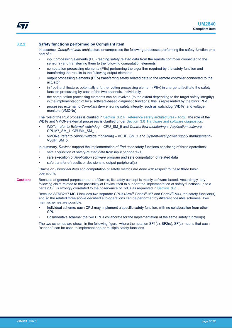
3.2.2 Safety functions performed by Compliant itemIn essence, Compliant item architecture encompasses the following processes performing the safety function or apart of it:• input processing elements (PEi) reading safety related data from the remote controller connected to the
sensor(s) and transferring them to the following computation elements• computation processing elements (PEc) performing the algorithm required by the safety function and
transferring the results to the following output elements• output processing elements (PEo) transferring safety related data to the remote controller connected to the
actuator• in 1oo2 architecture, potentially a further voting processing element (PEv) in charge to facilitate the safety
function processing by each of the two channels, individually.• the computation processing elements can be involved (to the extent depending to the target safety integrity)
in the implementation of local software-based diagnostic functions; this is represented by the block PEd• processes external to Compliant item ensuring safety integrity, such as watchdog (WDTe) and voltage
monitors (VMONe)
The role of the PEv process is clarified in Section 3.2.4 Reference safety architectures - 1oo2. The role of theWDTe and VMONe external processes is clarified under Section 3.6 Hardware and software diagnostics:• WDTe: refer to External watchdog – CPU_SM_5 and Control flow monitoring in Application software –
CPUM7_SM_1, CPUM4_SM_1,• VMONe: refer to Supply voltage monitoring – VSUP_SM_1 and System-level power supply management -
VSUP_SM_5.
In summary, Devices support the implementation of End user safety functions consisting of three operations:• safe acquisition of safety-related data from input peripheral(s)• safe execution of Application software program and safe computation of related data• safe transfer of results or decisions to output peripheral(s)
Claims on Compliant item and computation of safety metrics are done with respect to these three basicoperations.
Caution: Because of general purpose nature of Device, its safety concept is mainly software-based. Accordingly, anyfollowing claim related to the possibility of Device itself to support the implementation of safety functions up to acertain SIL is strongly correlated to the observance of CoUs as requested in Section 3.7 .Because STM32H7 MCU includes two separate CPUs (Arm® Cortex®-M7 and Cortex®-M4), the safety function(s)and so the related three above decribed sub-operations can be performed by different possible schemes. Twomain schemes are possible:• Individual scheme: each CPU may implement a specific safety function, with no collaboration from other
CPU• Collaborative scheme: the two CPUs collaborate for the implementation of the same safety function(s)
The two schemes are shown in the following figure, where the notation SF1(s), SF2(s), SF(s) means that each"channel" can be used to implement one or multiple safety functions.
UM2840Compliant item
UM2840 - Rev 1 page 6/132

Figure 3. Individual and collaborative schemes
PEi1 PEc1CPU1
PEo1
PEi2 PEo2PEc2CPU2
SF1(s)
SF2(s)
PEi12
Individual scheme
PEi PEc1CPU1
PEoPEc2CPU2
SF(s)
Collaborative scheme
The schemes can be embedded in the reference safety architectures described below.Consequences related to the coexistence on the two CPUs in the same MCU are embedded in related AssumedSafety Requirements (refer to Section 3.3 Safety analysis assumptions) and Conditon of Use (refer toSection 3.7 Conditions of use); related rationales are exposed in Section 3.2.5 The separation concept.According to the definition for implemented safety functions, Compliant item (element) can be regarded as type B(as per IEC 61508-2, 7.4.4.1.3 definition). Despite accurate, exhaustive and detailed failure analysis, Device hasto be considered as intrinsically complex. This implies its type B classification.Two main safety architectures are identified: 1oo1 (using one Device) and 1oo2 (using two Devices).
UM2840Compliant item
UM2840 - Rev 1 page 7/132

3.2.3 Reference safety architectures - 1oo11oo1 reference architecture (Figure 4) ensures safety integrity of Compliant item through combining Deviceinternal processes (implemented safety mechanisms) with external processes WDTe and VMONe. In thisarchitecture Device is considered intrinsically having hardware fault tolerance (HFT) equal to 0.1oo1 reference architecture targets safety integrity level (SIL) SIL2. Both individual and collaborative scheme arepossible.
3.2.3.1 Individual scheme
Figure 4. 1oo1 reference architecture - individual scheme
PEi1
PEd1
PEo1
PEi2 PEo2PEc2CPU2
SF1
SF2
PEc1CPU1
PEd2
Actuators 1
Actuators 2
Sensors
VMONe WDTe
PEi12
In the framework of individual scheme, the two chains PEi1/PEc1/PEo1 and PEi2/PEc2/PEo2 implement separatesets of safety function(s). Individual set of external actuators are involved in the safety function(s) implementation.Link between WDTe and actuators show the capability of the external watchdog to force the safe state.
Caution: All implemented safety function(s) share a common management for safe state and PST requirement - refer toSection 3.3 Safety analysis assumptions for related ASR.
3.2.3.2 Collaborative scheme
Figure 5. 1oo1 reference architecture - collaborative scheme
PEi
PEd1
PEoPEc2CPU2
PEc1CPU1
PEd2
ActuatorsSensors
VMONe WDTe
In the collaborative scheme, both CPUs are involved in the implementation of the same safety function(s). TheCPUs connection order is just informative and it is not constrained.
UM2840Compliant item
UM2840 - Rev 1 page 8/132
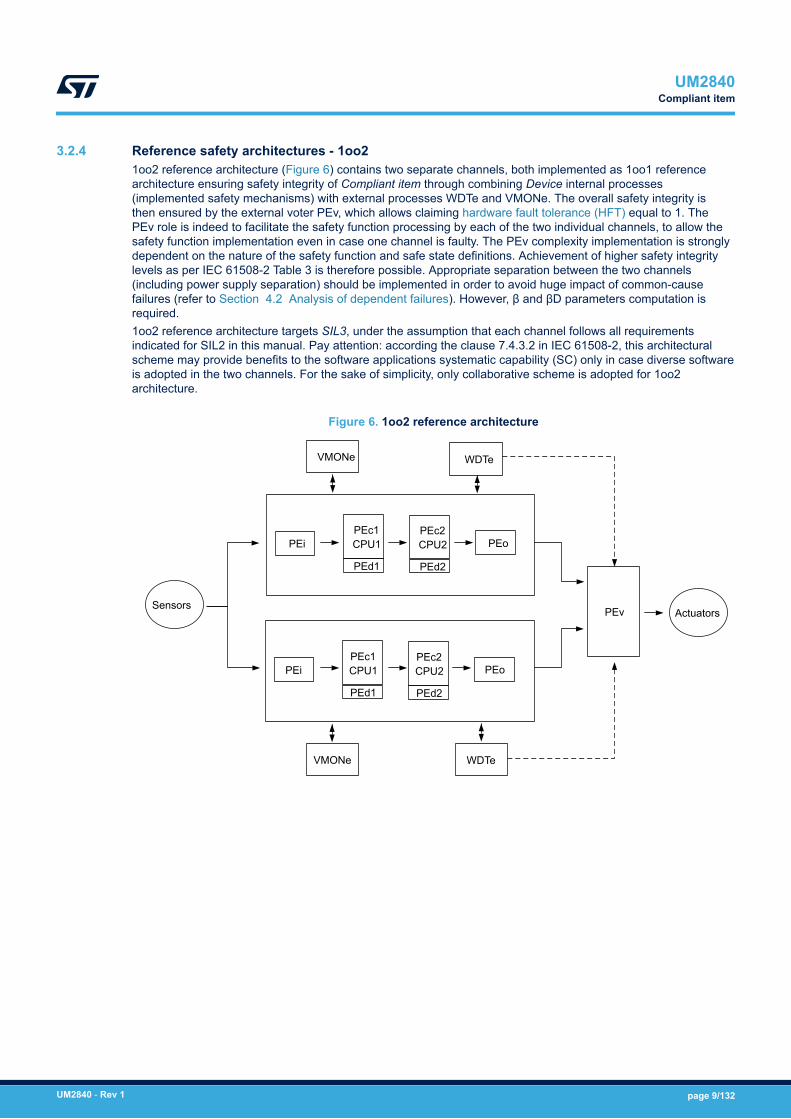
3.2.4 Reference safety architectures - 1oo21oo2 reference architecture (Figure 6) contains two separate channels, both implemented as 1oo1 referencearchitecture ensuring safety integrity of Compliant item through combining Device internal processes(implemented safety mechanisms) with external processes WDTe and VMONe. The overall safety integrity isthen ensured by the external voter PEv, which allows claiming hardware fault tolerance (HFT) equal to 1. ThePEv role is indeed to facilitate the safety function processing by each of the two individual channels, to allow thesafety function implementation even in case one channel is faulty. The PEv complexity implementation is stronglydependent on the nature of the safety function and safe state definitions. Achievement of higher safety integritylevels as per IEC 61508-2 Table 3 is therefore possible. Appropriate separation between the two channels(including power supply separation) should be implemented in order to avoid huge impact of common-causefailures (refer to Section 4.2 Analysis of dependent failures). However, β and βD parameters computation isrequired.1oo2 reference architecture targets SIL3, under the assumption that each channel follows all requirementsindicated for SIL2 in this manual. Pay attention: according the clause 7.4.3.2 in IEC 61508-2, this architecturalscheme may provide benefits to the software applications systematic capability (SC) only in case diverse softwareis adopted in the two channels. For the sake of simplicity, only collaborative scheme is adopted for 1oo2architecture.
Figure 6. 1oo2 reference architecture
PEi
PEd1
PEoPEc2CPU2
PEc1CPU1
PEd2
ActuatorsSensors
VMONe
WDTe
PEi
PEd1
PEoPEc2CPU2
PEc1CPU1
PEd2
VMONe
WDTe
PEv
UM2840Compliant item
UM2840 - Rev 1 page 9/132
3.2.5 The separation conceptThe coexistence of two different CPU (Arm® Cortex®-M7 and M4) on the Device is managed by the means ofthe STM32H7 dedicated separation concept, shown in this section. The separation concept mitigates potentialinterferences between the two CPUs (and their software) and it is composed by two different aspects, spatialseparation and temporal separation.
Spatial separation
Arm® Cortex®-M7 and M4 coexist on the same device and so they share the control and the access tocommon resources, like SRAM, Flash, peripherals. Interferences are therefore possible, but in the lack ofhardware-built segregation features for the CPUs, they are mitigated by a combination of requirements driving theimplementation of final application:• CoU_10 and CoU_11 forces the implementation of a kind of “private” SRAMs, one for each CPU, which
is quite valuable when individual scheme is adopted. Possible interferences are mitigated by the staticallocation of the SRAM and by dynamic checking performed by the two MPUs, as requested by CoU_12
• Because of CoU_15, each CPU has its “private” watchdog which can be triggered just by the CPUitself – this mitigates any potential issues related to the management of the required external watchdog.Furthermore, CoU_16 guarantee that the software routines charged of watchdog management and safetydata exchange between CPUs are always active because developed with highest systematic capability.
Temporal separation
The two CPUs Arm® Cortex®-M7 and M4 can boot in independent way and this makes them not strictly linkedfrom temporal point of view. Anyway, the effectiveness of the spatial separation (see above) is correlated tothe actual capability of prescribed hardware and software to correctly functioning. Accordingly, it is End userresponsibility to guarantee by system-level measures and solutions the safe state during the STM32H7 boot. TheCPU separation cannot be considered working until at least CoU_17 (startup tests) is satisfied.
UM2840Compliant item
UM2840 - Rev 1 page 10/132

3.3 Safety analysis assumptionsThis section collects all assumptions made during the safety analysis of the devices.
3.3.1 Safety requirement assumptionsThe safety concept specification, the overall safety requirement specification and the consequent allocationdetermine the requirements for Compliant item as further listed. ASR stands for assumed safety requirement.
Caution: It is End user’s responsibility to check the compliance of the final application with these assumptions.ASR1: Compliant item can be used to implement four kinds of safety function modes of operation according toIEC 61508-4,3.5.16:• a continuous mode (CM) or high-demand (HD) SIL3 safety function (CM3), or• a low-demand (LD) SIL3 safety function (LD3), or• a CM or HD SIL2 safety function (CM2), or• a LD SIL2 safety function (LD2).
ASR2: Compliant item is used to implement safety function(s) allowing a specific worst-case time budget (seenote below) for the STM32 MCU to detect and react to a failure. That time corresponds to the portion of theprocess safety time (PST) allocated to Device (STM32xx Series duty in Figure 7) in error reaction chain at systemlevel.In case of multiple safety functions implementation leading to multiple different time constraints, the shortest onemust be adopted for each safety function.
Note: As collateral effect, time constraint for the execution of periodical tests are always the same for both CPUs of theDevice.
Note: The computation for time budget mainly depends on the execution speed for periodic tests implementedby software. Such duration might depends on the actual amount of hardware resources (RAM memory,Flash memory, peripherals) actually declared as safety-related. Further constraints and requirements fromIEC 61508-2, 7.4.5.3 must be considered.
Figure 7. Allocation and target for STM32 PST
System-level PST
MCU detection FW reaction SW reaction Actuator reaction
STM32xx Series duty End user duty….
ASR3.1: Compliant item is used to implement safety function(s) that can be continuously powered on for a periodover eight hours. It is assumed to not require any proof test, and the lifetime of the product is considered to be noless than 10 years.ASR3.2: It is assumed that the Device operates within specified electrical specifications and environment limits.The End user is responsible for the compliance to this assumption.ASR 4.1: It is assumed that both CPUs available in the Device (Arm® Cortex®-M7 and M4) are considered assafety related.ASR4.2: It is assumed that in case multiple safety functions are implemented in the Compliant item, all functionsare classified with the same SIL for hardware safety integrity and the same SC for software systematic capabilityand therefore they are not distinguishable in terms of their safety requirements.ASR4.3: In case of multiple safety function implementations, it is assumed that End user is responsible to dulyensure their mutual independence.ASR4.4: It is assumed that there are no non-safety-related functions implemented in Application software,coexisting with safety functions.
UM2840Safety analysis assumptions
UM2840 - Rev 1 page 11/132

ASR5: It is assumed that the implemented safety function(s) does (do) not depend on transition of Device (or oneof its CPUs) to and from a low-power state.ASR6.1: The local safe state of Compliant item is the one in which either:• SS1: Application software(1) is informed by the presence of a fault and a reaction by Application software
itself is possible.• SS2: Application software(1) cannot be informed by the presence of a fault or Application software is not able
to execute a reaction.
Note: End user must take into account that random hardware failures affecting Device can compromise its operation(for example failure modes affecting the program counter prevent the correct execution of software).
The following table provides details on the SS1 and SS2 safe states.
Table 2. SS1 and SS2 safe state details
Safestate Condition Compliant
item action
System transitionto safe state -
1oo1 architecture(individual scheme)
System transitionto safe state –
1oo1 architecture(collaborative scheme)
System transition tosafe state – 1oo2
architecture
SS1
Application software(1)
is informed by thepresence of a faultand a reaction byApplication softwareitself is possible.
Fault reportingto Applicationsoftware
Application software(1)
drives all implementedsafety functions in theirsafe state, possiblyleveraging on inter-CPU communications(CPU_SM_11)
Application software(1)
drives the overallsystem in its safe state
Application software(1)
in one of the twochannels drives theoverall system in itssafe state
SS2
Application software(1)
cannot be informed bythe presence of a faultor Application softwareis not able to executea reaction.
Reset signalissued byWDTe
WDTe drives allimplemented safetyfunctions in their safestate (“safe shutdown”)(2)
WDTe drives the overallsystem in its safe state(“safe shutdown”)(2)
PEv drives the overallsystem in its safe state
1. Any of the application software running on the two different CPUs available on Device, Arm Cortex M7 and M4 (or even bothof them).
2. The safe state achievement intended here is compliant to Note on IEC 61508-2, 7.4.8.1
ASR6.2: It is assumed that the safe state(s) defined at system level by End user is compatible with the assumedlocal safe state (SS1, SS2) for Compliant item.ASR6.3: When individual scheme is adopted, it is assumed that the safe state defined at system level iscompatible with the causal connection between the individual safe state of each safety functions described inTable 2.
Note: According to the requirements listed on Table 2, the detection of a fault must cause the transition to safe statefor each implemented safety functions. Accordingly, even if in priciple different safe states can be defined for thedifferent implemented safety functions, their time evolution cannot be kept separated.ASR7: Compliant item is assumed to be analyzed according to routes 1H and 1S of IEC 61508-2.
Note: Refer to Section 3.5 Systematic safety integrity and Section 3.6 Hardware and software diagnostics.ASR8: Compliant item is assumed to be regarded as type B, as per IEC 61508-2, 7.4.4.1.3.ASR9.1: It is assumed that STM32H7 is not used to build fail-operational solutions based exclusively on thepresence of two different CPUs in the device itself.ASR9.2: It is assumed that a single STM32H7 instance is not used to build a HFT>0 solutions based exclusivelyon the presence of two different CPUs in the device itself.ASR9.3: It is assumed that the architecture 1oo1 with individual scheme (see Section 3.2.3 Reference safetyarchitectures - 1oo1) is not used to artificially implement a 1oo2 scheme with one single STM32H7 device
Note: This assumption is placed to avoid the implementation of the same safety function of the two separate CPUsin the individual scheme, managed then with an external voter. That solution cannot be considered a true 1oo2architecture as described in IEC 61508-6 because of the incomplete separation between the two channels.
UM2840Safety analysis assumptions
UM2840 - Rev 1 page 12/132
ASR10: When adopting individual scheme, is End user responsibility to prove the freedom from interferencesbetween physical pins associated to different safety functions (e.g. by running a pin-level FMEDA).ASR11: It is assumed that is End user responsibility to correct manage the CPUs boot process (by the handling ofBOOT options) in order of implementing a boot process compliant to all requirements included in this manual.
3.4 Electrical specifications and environment limitsTo ensure safety integrity, the user must operate Device(s) within its (their) specified:• absolute maximum rating• capacity• operating conditions
For electrical specifications and environmental limits of Device(s), refer to its (their) technical documentation suchas datasheet(s) and reference manual(s) available on www.st.com.
Note: The device operation within specified limits is a prerequisite for the correct implementation of any safetyfunction. This is explicitly assumed within the assumptions (refer to above ASR3.2).
3.5 Systematic safety integrityAccording to the requirements of IEC 61508-2, 7.4.2.2, the Route 1S is considered in the analysis of Device(s).As clearly authorized by IEC 61508-2, 7.4.6.1, STM32 MCU products can be considered as standard, mass-produced electronic integrated devices, for which stringent development procedures, rigorous testing andextensive experience of use minimize the likelihood of design faults. However, ST internally assesses thecompliance of the Device development flow, through techniques and measures suggested in the IEC 61508-2Annex F. A safety case database (see Section 5 List of evidences) keeps evidences of the current compliancelevel to the norm.
UM2840Electrical specifications and environment limits
UM2840 - Rev 1 page 13/132
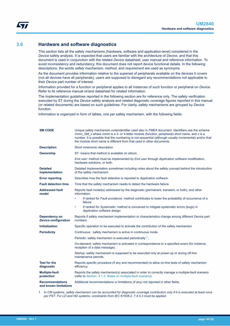
3.6 Hardware and software diagnosticsThis section lists all the safety mechanisms (hardware, software and application-level) considered in theDevice safety analysis. It is expected that users are familiar with the architecture of Device, and that thisdocument is used in conjunction with the related Device datasheet, user manual and reference information. Toavoid inconsistency and redundancy, this document does not report device functional details. In the followingdescriptions, the words safety mechanism, method, and requirement are used as synonyms.As the document provides information relative to the superset of peripherals available on the devices it covers(not all devices have all peripherals), users are supposed to disregard any recommendations not applicable totheir Device part number of interest.Information provided for a function or peripheral applies to all instances of such function or peripheral on Device.Refer to its reference manual or/and datasheet for related information.The implementation guidelines reported in the following section are for reference only. The safety verificationexecuted by ST during the Device safety analysis and related diagnostic coverage figures reported in this manual(or related documents) are based on such guidelines. For clarity, safety mechanisms are grouped by Devicefunction.Information is organized in form of tables, one per safety mechanism, with the following fields:
SM CODE Unique safety mechanism code/identifier used also in FMEA document. Identifiers use the schememmm_SM_x where mmm is a 3- or 4-letter module (function, peripheral) short name, and x is anumber. It is possible that the numbering is not sequential (although usually incremental) and/or thatthe module short name is different from that used in other documents.
Description Short mnemonic description
Ownership ST: means that method is available on silicon.
End user: method must be implemented by End user through Application software modification,hardware solutions, or both.
Detailedimplementation
Detailed implementation sometimes including notes about the safety concept behind the introductionof the safety mechanism.
Error reporting Describes how the fault detection is reported to Application software.
Fault detection time Time that the safety mechanism needs to detect the hardware failure.
Addressed faultmodel
Reports fault model(s) addressed by the diagnostic (permanent, transient, or both), and otherinformation:• If ranked for Fault avoidance: method contributes to lower the probability of occurrence of a
failure• If ranked for Systematic: method is conceived to mitigate systematic errors (bugs) in
Application software design
Dependency onDevice configuration
Reports if safety mechanism implementation or characteristics change among different Device partnumbers.
Initialization Specific operation to be executed to activate the contribution of the safety mechanism
Periodicity Continuous : safety mechanism is active in continuous mode.
Periodic: safety mechanism is executed periodically(1).
On-demand: safety mechanism is activated in correspondence to a specified event (for instance,reception of a data message).
Startup: safety mechanism is supposed to be executed only at power-up or during off-linemaintenance periods.
Test for thediagnostic
Reports specific procedure (if any and recommended) to allow on-line tests of safety mechanismefficiency.
Multiple-faultprotection
Reports the safety mechanism(s) associated in order to correctly manage a multiple-fault scenario(refer to Section 4.1.3 Notes on multiple-fault scenario).
Recommendationsand known limitations
Additional recommendations or limitations (if any) not reported in other fields.
1. In CM systems, safety mechanism can be accounted for diagnostic coverage contribution only if it is executed at least onceper PST. For LD and HD systems, constraints from IEC 61508-2, 7.4.5.3 must be applied.
UM2840Hardware and software diagnostics
UM2840 - Rev 1 page 14/132

3.6.1 Arm® Cortex®-M7 CPU
Table 3. CPUM7_SM_0
SM CODE CPUM7_SM_0
Description Periodical core self-test software for Arm® Cortex®-M7 CPU
Ownership End user or ST
Detailed implementation
The software test is built around well-known techniques already addressed by IEC 61508-7,A.3.2 (Self-test by software: walking bit one-channel). To reach the required values ofcoverage, the self-test software is specified by means of a detailed analysis of all the CPUfailure modes and related failure modes distribution
Error reporting Depends on implementation
Fault detection time Depends on implementation
Addressed fault model Permanent
Dependency on Device configuration None
Initialization None
Periodicity Periodic
Test for the diagnosticSelf-diagnostic capabilities can be embedded in the software, according the testimplementation design strategy chosen. The adoption of checksum protection on resultsvariables and defensive programming are recommended.
Multiple-fault protection CPU_SM_5: external watchdog
Recommendations and known limitations
This method is the main asset in STM32H7 dual-core safety concept. CPU integrity is a keyfactor because the defined diagnostics for MCU peripherals are to major part software-based.
Startup execution of this safety mechanism is recommended for multiple fault mitigations -refer to Section 4.1.3 Notes on multiple-fault scenario for details.
UM2840Hardware and software diagnostics
UM2840 - Rev 1 page 15/132
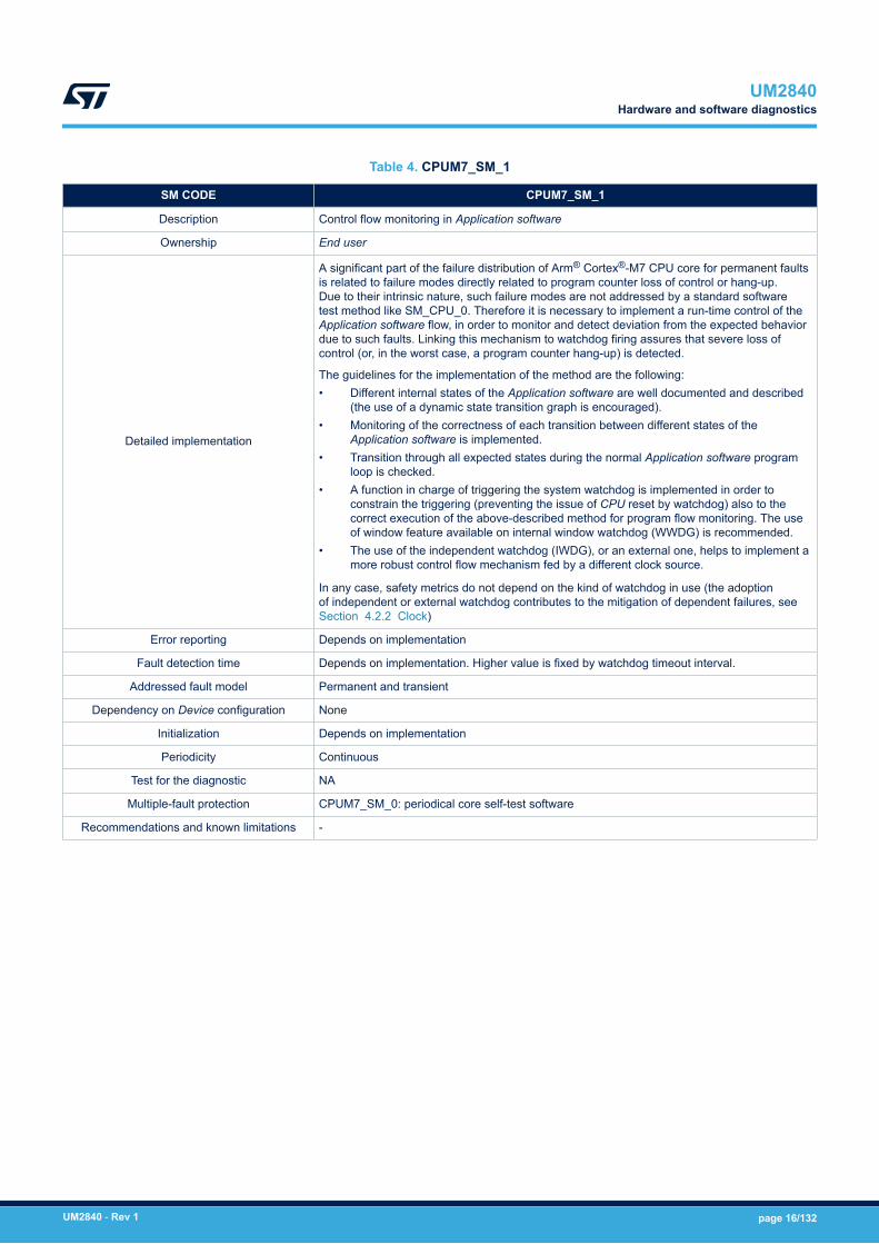
Table 4. CPUM7_SM_1
SM CODE CPUM7_SM_1
Description Control flow monitoring in Application software
Ownership End user
Detailed implementation
A significant part of the failure distribution of Arm® Cortex®-M7 CPU core for permanent faultsis related to failure modes directly related to program counter loss of control or hang-up.Due to their intrinsic nature, such failure modes are not addressed by a standard softwaretest method like SM_CPU_0. Therefore it is necessary to implement a run-time control of theApplication software flow, in order to monitor and detect deviation from the expected behaviordue to such faults. Linking this mechanism to watchdog firing assures that severe loss ofcontrol (or, in the worst case, a program counter hang-up) is detected.
The guidelines for the implementation of the method are the following:• Different internal states of the Application software are well documented and described
(the use of a dynamic state transition graph is encouraged).• Monitoring of the correctness of each transition between different states of the
Application software is implemented.• Transition through all expected states during the normal Application software program
loop is checked.• A function in charge of triggering the system watchdog is implemented in order to
constrain the triggering (preventing the issue of CPU reset by watchdog) also to thecorrect execution of the above-described method for program flow monitoring. The useof window feature available on internal window watchdog (WWDG) is recommended.
• The use of the independent watchdog (IWDG), or an external one, helps to implement amore robust control flow mechanism fed by a different clock source.
In any case, safety metrics do not depend on the kind of watchdog in use (the adoptionof independent or external watchdog contributes to the mitigation of dependent failures, seeSection 4.2.2 Clock)
Error reporting Depends on implementation
Fault detection time Depends on implementation. Higher value is fixed by watchdog timeout interval.
Addressed fault model Permanent and transient
Dependency on Device configuration None
Initialization Depends on implementation
Periodicity Continuous
Test for the diagnostic NA
Multiple-fault protection CPUM7_SM_0: periodical core self-test software
Recommendations and known limitations -
UM2840Hardware and software diagnostics
UM2840 - Rev 1 page 16/132
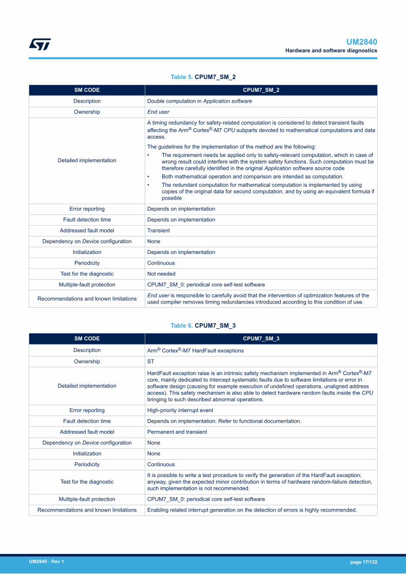
Table 5. CPUM7_SM_2
SM CODE CPUM7_SM_2
Description Double computation in Application software
Ownership End user
Detailed implementation
A timing redundancy for safety-related computation is considered to detect transient faultsaffecting the Arm® Cortex®-M7 CPU subparts devoted to mathematical computations and dataaccess.
The guidelines for the implementation of the method are the following:• The requirement needs be applied only to safety-relevant computation, which in case of
wrong result could interfere with the system safety functions. Such computation must betherefore carefully identified in the original Application software source code
• Both mathematical operation and comparison are intended as computation.• The redundant computation for mathematical computation is implemented by using
copies of the original data for second computation, and by using an equivalent formula ifpossible
Error reporting Depends on implementation
Fault detection time Depends on implementation
Addressed fault model Transient
Dependency on Device configuration None
Initialization Depends on implementation
Periodicity Continuous
Test for the diagnostic Not needed
Multiple-fault protection CPUM7_SM_0: periodical core self-test software
Recommendations and known limitations End user is responsible to carefully avoid that the intervention of optimization features of theused compiler removes timing redundancies introduced according to this condition of use.
Table 6. CPUM7_SM_3
SM CODE CPUM7_SM_3
Description Arm® Cortex®-M7 HardFault exceptions
Ownership ST
Detailed implementation
HardFault exception raise is an intrinsic safety mechanism implemented in Arm® Cortex®-M7core, mainly dedicated to intercept systematic faults due to software limitations or error insoftware design (causing for example execution of undefined operations, unaligned addressaccess). This safety mechanism is also able to detect hardware random faults inside the CPUbringing to such described abnormal operations.
Error reporting High-priority interrupt event
Fault detection time Depends on implementation. Refer to functional documentation.
Addressed fault model Permanent and transient
Dependency on Device configuration None
Initialization None
Periodicity Continuous
Test for the diagnosticIt is possible to write a test procedure to verify the generation of the HardFault exception;anyway, given the expected minor contribution in terms of hardware random-failure detection,such implementation is not recommended.
Multiple-fault protection CPUM7_SM_0: periodical core self-test software
Recommendations and known limitations Enabling related interrupt generation on the detection of errors is highly recommended.
UM2840Hardware and software diagnostics
UM2840 - Rev 1 page 17/132

Table 7. CPUM7_SM_4
SM CODE CPUM7_SM_4
Description Stack hardening for Application software
Ownership End user
Detailed implementation
The stack hardening method is required to address faults (mainly transient) affectingArm® Cortex®-M7 CPU register bank. This method is based on source code modification,introducing information redundancy in register-passed information to called functions.
The guidelines for the implementation of the method are the following:• To pass also a redundant copy of the passed parameters values (possibly inverted) and
to execute a coherence check in the function.• To pass also a redundant copy of the passed pointers and to execute a coherence
check in the function.• For parameters that are not protected by redundancy, to implement defensive
programming techniques (plausibility check of passed values). For example enumeratedfields are to be checked for consistency.
Error reporting Depends on implementation
Fault detection time Depends on implementation
Addressed fault model Permanent and transient
Dependency on Device configuration None
Initialization Depends on implementation
Periodicity On demand
Test for the diagnostic Not needed
Multiple-fault protection CPUM7_SM_0: periodical core self-test software
Recommendations and known limitationsThis method partially overlaps with defensive programming techniques required by IEC 61508for software development. Therefore in presence of Application software qualified for safetyintegrity greater or equal to SC2, optimizations are possible.
UM2840Hardware and software diagnostics
UM2840 - Rev 1 page 18/132
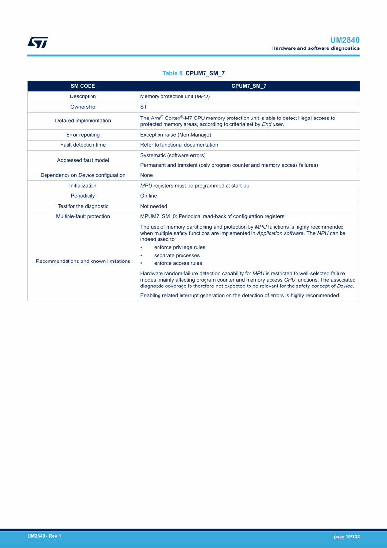
Table 8. CPUM7_SM_7
SM CODE CPUM7_SM_7
Description Memory protection unit (MPU)
Ownership ST
Detailed implementation The Arm® Cortex®-M7 CPU memory protection unit is able to detect illegal access toprotected memory areas, according to criteria set by End user.
Error reporting Exception raise (MemManage)
Fault detection time Refer to functional documentation
Addressed fault modelSystematic (software errors)
Permanent and transient (only program counter and memory access failures)
Dependency on Device configuration None
Initialization MPU registers must be programmed at start-up
Periodicity On line
Test for the diagnostic Not needed
Multiple-fault protection MPUM7_SM_0: Periodical read-back of configuration registers
Recommendations and known limitations
The use of memory partitioning and protection by MPU functions is highly recommendedwhen multiple safety functions are implemented in Application software. The MPU can beindeed used to• enforce privilege rules• separate processes• enforce access rules
Hardware random-failure detection capability for MPU is restricted to well-selected failuremodes, mainly affecting program counter and memory access CPU functions. The associateddiagnostic coverage is therefore not expected to be relevant for the safety concept of Device.
Enabling related interrupt generation on the detection of errors is highly recommended.
UM2840Hardware and software diagnostics
UM2840 - Rev 1 page 19/132
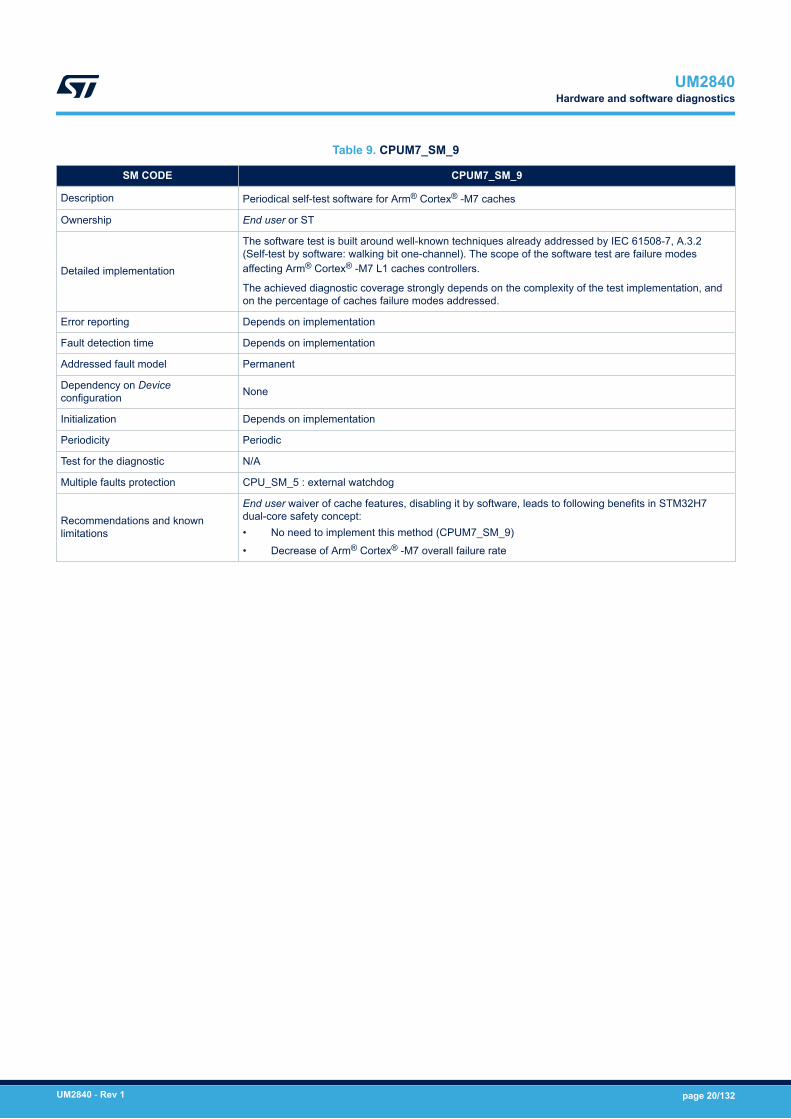
Table 9. CPUM7_SM_9
SM CODE CPUM7_SM_9
Description Periodical self-test software for Arm® Cortex® -M7 caches
Ownership End user or ST
Detailed implementation
The software test is built around well-known techniques already addressed by IEC 61508-7, A.3.2(Self-test by software: walking bit one-channel). The scope of the software test are failure modesaffecting Arm® Cortex® -M7 L1 caches controllers.
The achieved diagnostic coverage strongly depends on the complexity of the test implementation, andon the percentage of caches failure modes addressed.
Error reporting Depends on implementation
Fault detection time Depends on implementation
Addressed fault model Permanent
Dependency on Deviceconfiguration None
Initialization Depends on implementation
Periodicity Periodic
Test for the diagnostic N/A
Multiple faults protection CPU_SM_5 : external watchdog
Recommendations and knownlimitations
End user waiver of cache features, disabling it by software, leads to following benefits in STM32H7dual-core safety concept:• No need to implement this method (CPUM7_SM_9)
• Decrease of Arm® Cortex® -M7 overall failure rate
UM2840Hardware and software diagnostics
UM2840 - Rev 1 page 20/132
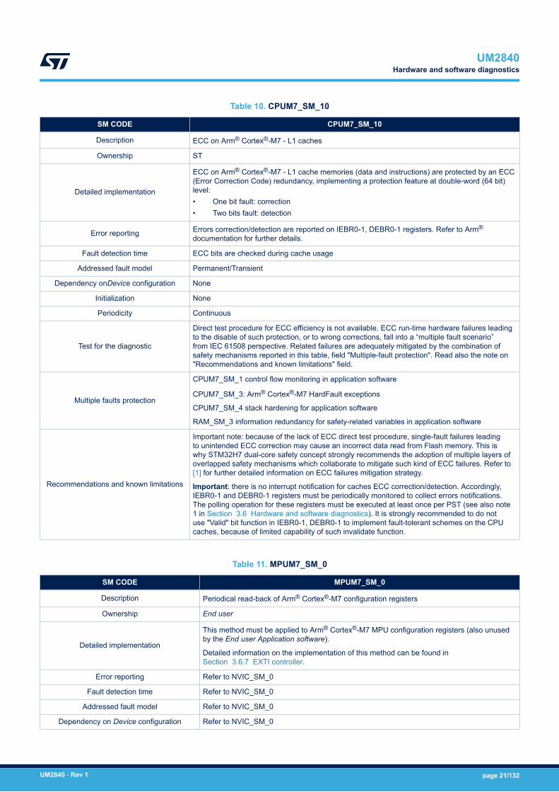
Table 10. CPUM7_SM_10
SM CODE CPUM7_SM_10
Description ECC on Arm® Cortex®-M7 - L1 caches
Ownership ST
Detailed implementation
ECC on Arm® Cortex®-M7 - L1 cache memories (data and instructions) are protected by an ECC(Error Correction Code) redundancy, implementing a protection feature at double-word (64 bit)level:• One bit fault: correction• Two bits fault: detection
Error reporting Errors correction/detection are reported on IEBR0-1, DEBR0-1 registers. Refer to Arm®
documentation for further details.
Fault detection time ECC bits are checked during cache usage
Addressed fault model Permanent/Transient
Dependency onDevice configuration None
Initialization None
Periodicity Continuous
Test for the diagnostic
Direct test procedure for ECC efficiency is not available. ECC run-time hardware failures leadingto the disable of such protection, or to wrong corrections, fall into a “multiple fault scenario”from IEC 61508 perspective. Related failures are adequately mitigated by the combination ofsafety mechanisms reported in this table, field "Multiple-fault protection". Read also the note on"Recommendations and known limitations" field.
Multiple faults protection
CPUM7_SM_1 control flow monitoring in application software
CPUM7_SM_3: Arm® Cortex®-M7 HardFault exceptions
CPUM7_SM_4 stack hardening for application software
RAM_SM_3 information redundancy for safety-related variables in application software
Recommendations and known limitations
Important note: because of the lack of ECC direct test procedure, single-fault failures leadingto unintended ECC correction may cause an incorrect data read from Flash memory. This iswhy STM32H7 dual-core safety concept strongly recommends the adoption of multiple layers ofoverlapped safety mechanisms which collaborate to mitigate such kind of ECC failures. Refer to[1] for further detailed information on ECC failures mitigation strategy.
Important: there is no interrupt notification for caches ECC correction/detection. Accordingly,IEBR0-1 and DEBR0-1 registers must be periodically monitored to collect errors notifications.The polling operation for these registers must be executed at least once per PST (see also note1 in Section 3.6 Hardware and software diagnostics). It is strongly recommended to do notuse "Valid" bit function in IEBR0-1, DEBR0-1 to implement fault-tolerant schemes on the CPUcaches, because of limited capability of such invalidate function.
Table 11. MPUM7_SM_0
SM CODE MPUM7_SM_0
Description Periodical read-back of Arm® Cortex®-M7 configuration registers
Ownership End user
Detailed implementation
This method must be applied to Arm® Cortex®-M7 MPU configuration registers (also unusedby the End user Application software).
Detailed information on the implementation of this method can be found inSection 3.6.7 EXTI controller.
Error reporting Refer to NVIC_SM_0
Fault detection time Refer to NVIC_SM_0
Addressed fault model Refer to NVIC_SM_0
Dependency on Device configuration Refer to NVIC_SM_0
UM2840Hardware and software diagnostics
UM2840 - Rev 1 page 21/132
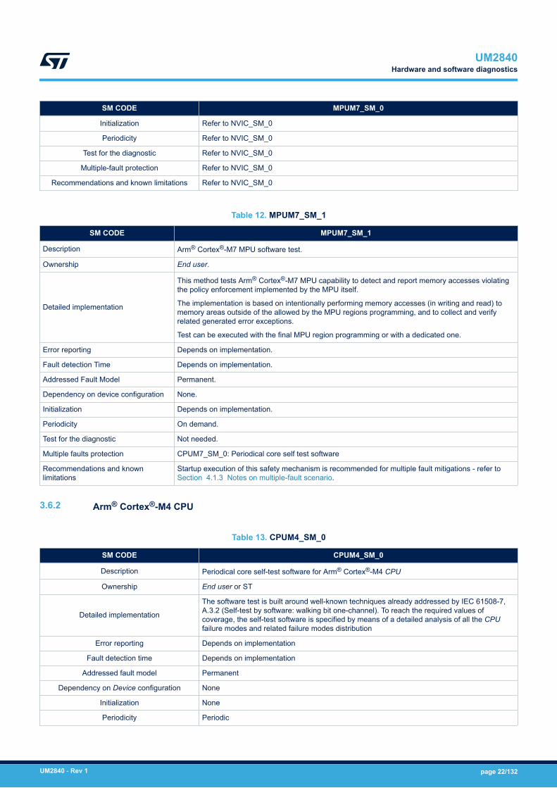
SM CODE MPUM7_SM_0
Initialization Refer to NVIC_SM_0
Periodicity Refer to NVIC_SM_0
Test for the diagnostic Refer to NVIC_SM_0
Multiple-fault protection Refer to NVIC_SM_0
Recommendations and known limitations Refer to NVIC_SM_0
Table 12. MPUM7_SM_1
SM CODE MPUM7_SM_1
Description Arm® Cortex®-M7 MPU software test.
Ownership End user.
Detailed implementation
This method tests Arm® Cortex®-M7 MPU capability to detect and report memory accesses violatingthe policy enforcement implemented by the MPU itself.
The implementation is based on intentionally performing memory accesses (in writing and read) tomemory areas outside of the allowed by the MPU regions programming, and to collect and verifyrelated generated error exceptions.
Test can be executed with the final MPU region programming or with a dedicated one.
Error reporting Depends on implementation.
Fault detection Time Depends on implementation.
Addressed Fault Model Permanent.
Dependency on device configuration None.
Initialization Depends on implementation.
Periodicity On demand.
Test for the diagnostic Not needed.
Multiple faults protection CPUM7_SM_0: Periodical core self test software
Recommendations and knownlimitations
Startup execution of this safety mechanism is recommended for multiple fault mitigations - refer toSection 4.1.3 Notes on multiple-fault scenario.
3.6.2 Arm® Cortex®-M4 CPU
Table 13. CPUM4_SM_0
SM CODE CPUM4_SM_0
Description Periodical core self-test software for Arm® Cortex®-M4 CPU
Ownership End user or ST
Detailed implementation
The software test is built around well-known techniques already addressed by IEC 61508-7,A.3.2 (Self-test by software: walking bit one-channel). To reach the required values ofcoverage, the self-test software is specified by means of a detailed analysis of all the CPUfailure modes and related failure modes distribution
Error reporting Depends on implementation
Fault detection time Depends on implementation
Addressed fault model Permanent
Dependency on Device configuration None
Initialization None
Periodicity Periodic
UM2840Hardware and software diagnostics
UM2840 - Rev 1 page 22/132

SM CODE CPUM4_SM_0
Test for the diagnosticSelf-diagnostic capabilities can be embedded in the software, according the testimplementation design strategy chosen. The adoption of checksum protection on resultsvariables and defensive programming are recommended.
Multiple-fault protection CPU_SM_5: external watchdog
Recommendations and known limitations
This method is the main asset in STM32H7 dual-core safety concept. CPU integrity is a keyfactor because the defined diagnostics for MCU peripherals are to major part software-based.
Startup execution of this safety mechanism is recommended for multiple fault mitigations -refer to Section 4.1.3 Notes on multiple-fault scenario for details.
Table 14. CPUM4_SM_1
SM CODE CPUM4_SM_1
Description Control flow monitoring in Application software
Ownership End user
Detailed implementation
A significant part of the failure distribution of Arm® Cortex®-M4 CPU core for permanent faultsis related to failure modes directly related to program counter loss of control or hang-up.Due to their intrinsic nature, such failure modes are not addressed by a standard softwaretest method like SM_CPU_0. Therefore it is necessary to implement a run-time control of theApplication software flow, in order to monitor and detect deviation from the expected behaviordue to such faults. Linking this mechanism to watchdog firing assures that severe loss ofcontrol (or, in the worst case, a program counter hang-up) is detected.
The guidelines for the implementation of the method are the following:• Different internal states of the Application software are well documented and described
(the use of a dynamic state transition graph is encouraged).• Monitoring of the correctness of each transition between different states of the
Application software is implemented.• Transition through all expected states during the normal Application software program
loop is checked.• A function in charge of triggering the system watchdog is implemented in order to
constrain the triggering (preventing the issue of CPU reset by watchdog) also to thecorrect execution of the above-described method for program flow monitoring. The useof window feature available on internal window watchdog (WWDG) is recommended.
• The use of the independent watchdog (IWDG), or an external one, helps to implement amore robust control flow mechanism fed by a different clock source.
In any case, safety metrics do not depend on the kind of watchdog in use (the adoptionof independent or external watchdog contributes to the mitigation of dependent failures, seeSection 4.2.2 Clock)
Error reporting Depends on implementation
Fault detection time Depends on implementation. Higher value is fixed by watchdog timeout interval.
Addressed fault model Permanent and transient
Dependency on Device configuration None
Initialization Depends on implementation
Periodicity Continuous
Test for the diagnostic NA
Multiple-fault protection CPUM4_SM_0: periodical core self-test software
Recommendations and known limitations -
UM2840Hardware and software diagnostics
UM2840 - Rev 1 page 23/132

Table 15. CPUM4_SM_2
SM CODE CPUM4_SM_2
Description Double computation in Application software
Ownership End user
Detailed implementation
A timing redundancy for safety-related computation is considered to detect transient faultsaffecting the Arm® Cortex®-M4 CPU subparts devoted to mathematical computations and dataaccess.
The guidelines for the implementation of the method are the following:• The requirement needs be applied only to safety-relevant computation, which in case of
wrong result could interfere with the system safety functions. Such computation must betherefore carefully identified in the original Application software source code
• Both mathematical operation and comparison are intended as computation.• The redundant computation for mathematical computation is implemented by using
copies of the original data for second computation, and by using an equivalent formula ifpossible
Error reporting Depends on implementation
Fault detection time Depends on implementation
Addressed fault model Transient
Dependency on Device configuration None
Initialization Depends on implementation
Periodicity Continuous
Test for the diagnostic Not needed
Multiple-fault protection CPUM4_SM_0: periodical core self-test software
Recommendations and known limitations End user is responsible to carefully avoid that the intervention of optimization features of theused compiler removes timing redundancies introduced according to this condition of use.
Table 16. CPUM4_SM_3
SM CODE CPUM4_SM_3
Description Arm® Cortex®-M4 HardFault exceptions
Ownership ST
Detailed implementation
HardFault exception raise is an intrinsic safety mechanism implemented in Arm® Cortex®-M4core, mainly dedicated to intercept systematic faults due to software limitations or error insoftware design (causing for example execution of undefined operations, unaligned addressaccess). This safety mechanism is also able to detect hardware random faults inside the CPUbringing to such described abnormal operations.
Error reporting High-priority interrupt event
Fault detection time Depends on implementation. Refer to functional documentation.
Addressed fault model Permanent and transient
Dependency on Device configuration None
Initialization None
Periodicity Continuous
Test for the diagnosticIt is possible to write a test procedure to verify the generation of the HardFault exception;anyway, given the expected minor contribution in terms of hardware random-failure detection,such implementation is not recommended.
Multiple-fault protection CPUM4_SM_0: periodical core self-test software
Recommendations and known limitations Enabling related interrupt generation on the detection of errors is highly recommended.
UM2840Hardware and software diagnostics
UM2840 - Rev 1 page 24/132
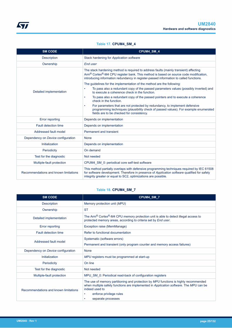
Table 17. CPUM4_SM_4
SM CODE CPUM4_SM_4
Description Stack hardening for Application software
Ownership End user
Detailed implementation
The stack hardening method is required to address faults (mainly transient) affectingArm® Cortex®-M4 CPU register bank. This method is based on source code modification,introducing information redundancy in register-passed information to called functions.
The guidelines for the implementation of the method are the following:• To pass also a redundant copy of the passed parameters values (possibly inverted) and
to execute a coherence check in the function.• To pass also a redundant copy of the passed pointers and to execute a coherence
check in the function.• For parameters that are not protected by redundancy, to implement defensive
programming techniques (plausibility check of passed values). For example enumeratedfields are to be checked for consistency.
Error reporting Depends on implementation
Fault detection time Depends on implementation
Addressed fault model Permanent and transient
Dependency on Device configuration None
Initialization Depends on implementation
Periodicity On demand
Test for the diagnostic Not needed
Multiple-fault protection CPUM4_SM_0: periodical core self-test software
Recommendations and known limitationsThis method partially overlaps with defensive programming techniques required by IEC 61508for software development. Therefore in presence of Application software qualified for safetyintegrity greater or equal to SC2, optimizations are possible.
Table 18. CPUM4_SM_7
SM CODE CPUM4_SM_7
Description Memory protection unit (MPU)
Ownership ST
Detailed implementation The Arm® Cortex®-M4 CPU memory protection unit is able to detect illegal access toprotected memory areas, according to criteria set by End user.
Error reporting Exception raise (MemManage)
Fault detection time Refer to functional documentation
Addressed fault modelSystematic (software errors)
Permanent and transient (only program counter and memory access failures)
Dependency on Device configuration None
Initialization MPU registers must be programmed at start-up
Periodicity On line
Test for the diagnostic Not needed
Multiple-fault protection MPU_SM_0: Periodical read-back of configuration registers
Recommendations and known limitations
The use of memory partitioning and protection by MPU functions is highly recommendedwhen multiple safety functions are implemented in Application software. The MPU can beindeed used to• enforce privilege rules• separate processes
UM2840Hardware and software diagnostics
UM2840 - Rev 1 page 25/132

SM CODE CPUM4_SM_7• enforce access rules
Hardware random-failure detection capability for MPU is restricted to well-selected failuremodes, mainly affecting program counter and memory access CPU functions. The associateddiagnostic coverage is therefore not expected to be relevant for the safety concept of Device.
Enabling related interrupt generation on the detection of errors is highly recommended.
Table 19. MPUM4_SM_0
SM CODE MPUM4_SM_0
Description Periodical read-back of Arm® Cortex®-M4 MPU configuration registers
Ownership End user
Detailed implementation
This method must be applied to Arm® Cortex®-M4 MPU configuration registers (also unusedby the End user Application software).
Detailed information on the implementation of this method can be found inSection 3.6.7 EXTI controller.
Error reporting Refer to NVIC_SM_0
Fault detection time Refer to NVIC_SM_0
Addressed fault model Refer to NVIC_SM_0
Dependency on Device configuration Refer to NVIC_SM_0
Initialization Refer to NVIC_SM_0
Periodicity Refer to NVIC_SM_0
Test for the diagnostic Refer to NVIC_SM_0
Multiple-fault protection Refer to NVIC_SM_0
Recommendations and known limitations Refer to NVIC_SM_0
Table 20. MPUM4_SM_1
SM CODE MPUM4_SM_1
Description Arm® Cortex®-M4 MPU software test.
Ownership End user.
Detailed implementation
This method tests Arm® Cortex®-M4 MPU capability to detect and report memory accesses violatingthe policy enforcement implemented by the MPU itself.
The implementation is based on intentionally performing memory accesses (in writing and read) tomemory areas outside of the allowed by the MPU regions programming, and to collect and verifyrelated generated error exceptions.
Test can be executed with the final MPU region programming or with a dedicated one.
Error reporting Depends on implementation.
Fault detection Time Depends on implementation.
Addressed Fault Model Permanent.
Dependency on device configuration None.
Initialization Depends on implementation.
Periodicity On demand.
Test for the diagnostic Not needed.
Multiple faults protection CPUM4_SM_0: Periodical core self test software
UM2840Hardware and software diagnostics
UM2840 - Rev 1 page 26/132
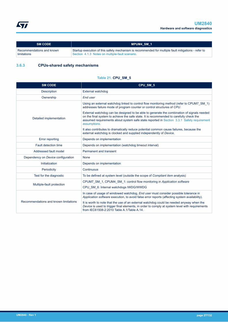
SM CODE MPUM4_SM_1
Recommendations and knownlimitations
Startup execution of this safety mechanism is recommended for multiple fault mitigations - refer toSection 4.1.3 Notes on multiple-fault scenario.
3.6.3 CPUs-shared safety mechanisms
Table 21. CPU_SM_5
SM CODE CPU_SM_5
Description External watchdog
Ownership End user
Detailed implementation
Using an external watchdog linked to control flow monitoring method (refer to CPUM7_SM_1)addresses failure mode of program counter or control structures of CPU.
External watchdog can be designed to be able to generate the combination of signals neededon the final system to achieve the safe state. It is recommended to carefully check theassumed requirements about system safe state reported in Section 3.3.1 Safety requirementassumptions.
It also contributes to dramatically reduce potential common cause failures, because theexternal watchdog is clocked and supplied independently of Device.
Error reporting Depends on implementation
Fault detection time Depends on implementation (watchdog timeout interval)
Addressed fault model Permanent and transient
Dependency on Device configuration None
Initialization Depends on implementation
Periodicity Continuous
Test for the diagnostic To be defined at system level (outside the scope of Compliant item analysis)
Multiple-fault protectionCPUM7_SM_1, CPUM4_SM_1: control flow monitoring in Application software
CPU_SM_6: Internal watchdogs IWDG/WWDG
Recommendations and known limitations
In case of usage of windowed watchdog, End user must consider possible tolerance inApplication software execution, to avoid false error reports (affecting system availability).
It is worth to note that the use of an external watchdog could be needed anyway when theDevice is used to trigger final elements, in order to comply at system level with requirementsfrom IEC61508-2:2010 Table A.1/Table A.14.
UM2840Hardware and software diagnostics
UM2840 - Rev 1 page 27/132
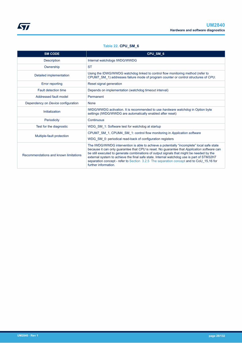
Table 22. CPU_SM_6
SM CODE CPU_SM_6
Description Internal watchdogs IWDG/WWDG
Ownership ST
Detailed implementation Using the IDWG/WWDG watchdog linked to control flow monitoring method (refer toCPUM7_SM_1) addresses failure mode of program counter or control structures of CPU.
Error reporting Reset signal generation
Fault detection time Depends on implementation (watchdog timeout interval)
Addressed fault model Permanent
Dependency on Device configuration None
Initialization IWDG/WWDG activation. It is recommended to use hardware watchdog in Option bytesettings (IWDG/WWDG are automatically enabled after reset)
Periodicity Continuous
Test for the diagnostic WDG_SM_1: Software test for watchdog at startup
Multiple-fault protectionCPUM7_SM_1, CPUM4_SM_1: control flow monitoring in Application software
WDG_SM_0: periodical read-back of configuration registers
Recommendations and known limitations
The IWDG/WWDG intervention is able to achieve a potentially “incomplete” local safe statebecause it can only guarantee that CPU is reset. No guarantee that Application software canbe still executed to generate combinations of output signals that might be needed by theexternal system to achieve the final safe state. Internal watchdog use is part of STM32H7separation concept - refer to Section 3.2.5 The separation concept and to CoU_15,16 forfurther information.
UM2840Hardware and software diagnostics
UM2840 - Rev 1 page 28/132
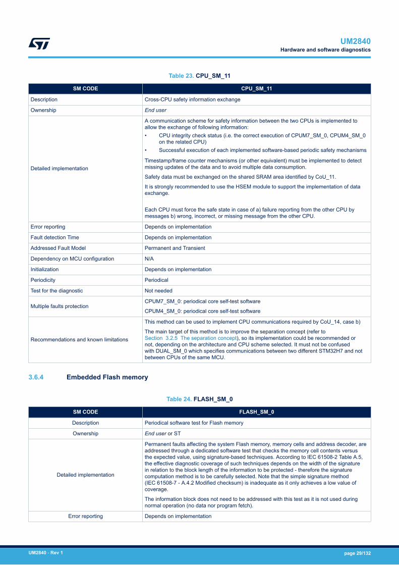
Table 23. CPU_SM_11
SM CODE CPU_SM_11
Description Cross-CPU safety information exchange
Ownership End user
Detailed implementation
A communication scheme for safety information between the two CPUs is implemented toallow the exchange of following information:• CPU integrity check status (i.e. the correct execution of CPUM7_SM_0, CPUM4_SM_0
on the related CPU)• Successful execution of each implemented software-based periodic safety mechanisms
Timestamp/frame counter mechanisms (or other equivalent) must be implemented to detectmissing updates of the data and to avoid multiple data consumption.
Safety data must be exchanged on the shared SRAM area identified by CoU_11.
It is strongly recommended to use the HSEM module to support the implementation of dataexchange.
Each CPU must force the safe state in case of a) failure reporting from the other CPU bymessages b) wrong, incorrect, or missing message from the other CPU.
Error reporting Depends on implementation
Fault detection Time Depends on implementation
Addressed Fault Model Permanent and Transient
Dependency on MCU configuration N/A
Initialization Depends on implementation
Periodicity Periodical
Test for the diagnostic Not needed
Multiple faults protectionCPUM7_SM_0: periodical core self-test software
CPUM4_SM_0: periodical core self-test software
Recommendations and known limitations
This method can be used to implement CPU communications required by CoU_14, case b)
The main target of this method is to improve the separation concept (refer toSection 3.2.5 The separation concept), so its implementation could be recommended ornot, depending on the architecture and CPU scheme selected. It must not be confusedwith DUAL_SM_0 which specifies communications between two different STM32H7 and notbetween CPUs of the same MCU.
3.6.4 Embedded Flash memory
Table 24. FLASH_SM_0
SM CODE FLASH_SM_0
Description Periodical software test for Flash memory
Ownership End user or ST
Detailed implementation
Permanent faults affecting the system Flash memory, memory cells and address decoder, areaddressed through a dedicated software test that checks the memory cell contents versusthe expected value, using signature-based techniques. According to IEC 61508-2 Table A.5,the effective diagnostic coverage of such techniques depends on the width of the signaturein relation to the block length of the information to be protected - therefore the signaturecomputation method is to be carefully selected. Note that the simple signature method(IEC 61508-7 - A.4.2 Modified checksum) is inadequate as it only achieves a low value ofcoverage.
The information block does not need to be addressed with this test as it is not used duringnormal operation (no data nor program fetch).
Error reporting Depends on implementation
UM2840Hardware and software diagnostics
UM2840 - Rev 1 page 29/132

SM CODE FLASH_SM_0
Fault detection time Depends on implementation
Addressed fault model Permanent
Dependency on Device configuration Flash memory size changes according part number
Initialization Memory signatures must be stored in Flash memory as well
Periodicity Periodic
Test for the diagnostic Self-diagnostic capabilities can be embedded in the software, according the testimplementation design strategy chosen
Multiple-fault protection
CPUM7_SM_0: Periodical core self-test software for Arm® Cortex®-M7 CPU
CPUM4_SM_0: Periodical core self-test software for Arm® Cortex®-M4 CPU
CPUM7_SM_1: control flow monitoring in application software
CPUM4_SM_1: control flow monitoring in application software
Recommendations and known limitations
This test is expected to have a relevant time duration – test integration must thereforeconsider the impact on application software execution.
The use of internal cyclic redundancy check (CRC) module is recommended. In principledirect memory access (DMA) feature for data transfer can be used.
Unused Flash memory sections can be excluded from testing.
Startup execution of this safety mechanism is recommended for multiple fault mitigations -refer to Section 4.1.3 Notes on multiple-fault scenario for details.
As far as ASR2 requirement on PST duration (adoption of the same value for both CPUs) andCoU_14 are correctly implemented, the overall Flash memory test can be partitioned amongthe two CPUs, or even delegated to only one.
Table 25. FLASH_SM_1
SM CODE FLASH_SM_1
Description Control flow monitoring in application software
Ownership End user
Detailed implementation
Permanent and transient faults affecting the system Flash memory, memory cells and addressdecoder, can interfere with the access operation by the CPU, leading to wrong data orinstruction fetches.
Such failures can be detected by control flow monitoring techniques implemented in theapplication software loaded from Flash memory.
For more details on the implementation, refer to description CPUM7_SM_1 andCPUM4_SM_1.
Error reporting Depends on implementation
Fault detection time Depends on implementation. Higher value is fixed by watchdog timeout interval.
Addressed fault model Permanent and Transient
Dependency on Device configuration None
Initialization Depends on implementation
Periodicity Continuous
Test for the diagnostic NA
Multiple-fault protection CPUM7_SM_0, CPUM4_SM_0: periodical core self-test software
Recommendations and known limitations CPUM7_SM_1 and CPUM4_SM_1 correct implementation supersedes this requirement.
UM2840Hardware and software diagnostics
UM2840 - Rev 1 page 30/132
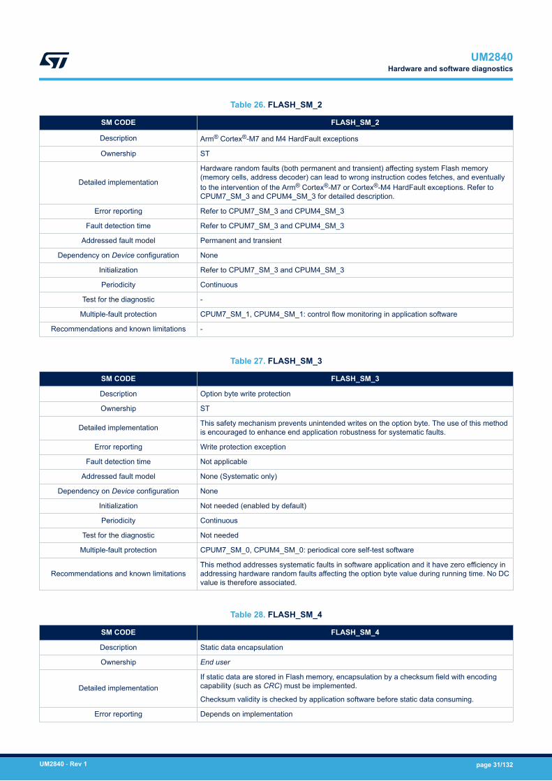
Table 26. FLASH_SM_2
SM CODE FLASH_SM_2
Description Arm® Cortex®-M7 and M4 HardFault exceptions
Ownership ST
Detailed implementation
Hardware random faults (both permanent and transient) affecting system Flash memory(memory cells, address decoder) can lead to wrong instruction codes fetches, and eventuallyto the intervention of the Arm® Cortex®-M7 or Cortex®-M4 HardFault exceptions. Refer toCPUM7_SM_3 and CPUM4_SM_3 for detailed description.
Error reporting Refer to CPUM7_SM_3 and CPUM4_SM_3
Fault detection time Refer to CPUM7_SM_3 and CPUM4_SM_3
Addressed fault model Permanent and transient
Dependency on Device configuration None
Initialization Refer to CPUM7_SM_3 and CPUM4_SM_3
Periodicity Continuous
Test for the diagnostic -
Multiple-fault protection CPUM7_SM_1, CPUM4_SM_1: control flow monitoring in application software
Recommendations and known limitations -
Table 27. FLASH_SM_3
SM CODE FLASH_SM_3
Description Option byte write protection
Ownership ST
Detailed implementation This safety mechanism prevents unintended writes on the option byte. The use of this methodis encouraged to enhance end application robustness for systematic faults.
Error reporting Write protection exception
Fault detection time Not applicable
Addressed fault model None (Systematic only)
Dependency on Device configuration None
Initialization Not needed (enabled by default)
Periodicity Continuous
Test for the diagnostic Not needed
Multiple-fault protection CPUM7_SM_0, CPUM4_SM_0: periodical core self-test software
Recommendations and known limitationsThis method addresses systematic faults in software application and it have zero efficiency inaddressing hardware random faults affecting the option byte value during running time. No DCvalue is therefore associated.
Table 28. FLASH_SM_4
SM CODE FLASH_SM_4
Description Static data encapsulation
Ownership End user
Detailed implementationIf static data are stored in Flash memory, encapsulation by a checksum field with encodingcapability (such as CRC) must be implemented.
Checksum validity is checked by application software before static data consuming.
Error reporting Depends on implementation
UM2840Hardware and software diagnostics
UM2840 - Rev 1 page 31/132
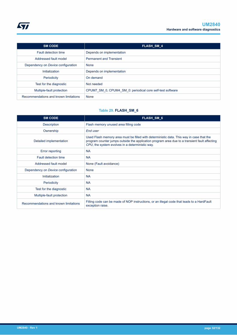
SM CODE FLASH_SM_4
Fault detection time Depends on implementation
Addressed fault model Permanent and Transient
Dependency on Device configuration None
Initialization Depends on implementation
Periodicity On demand
Test for the diagnostic Not needed
Multiple-fault protection CPUM7_SM_0, CPUM4_SM_0: periodical core self-test software
Recommendations and known limitations None
Table 29. FLASH_SM_6
SM CODE FLASH_SM_6
Description Flash memory unused area filling code
Ownership End user
Detailed implementationUsed Flash memory area must be filled with deterministic data. This way in case that theprogram counter jumps outside the application program area due to a transient fault affectingCPU, the system evolves in a deterministic way.
Error reporting NA
Fault detection time NA
Addressed fault model None (Fault avoidance)
Dependency on Device configuration None
Initialization NA
Periodicity NA
Test for the diagnostic NA
Multiple-fault protection NA
Recommendations and known limitations Filling code can be made of NOP instructions, or an illegal code that leads to a HardFaultexception raise.
UM2840Hardware and software diagnostics
UM2840 - Rev 1 page 32/132

Table 30. FLASH_SM_7
SM CODE FLASH_SM_7
Description ECC on Flash memory
Ownership ST
Detailed implementation
Internal Flash memory is protected by an ECC (Error Correction Code)redundancy, implementing a protection feature at double-word (64 bit)level:• One bit fault: correction• Two bits fault: detection
Error reporting
Correction:• Flag SNECCERR11/2 (ECC correction) is set in FLASH_SR1/2
register (FLASH_ECCR)• Interrupt is generated
Detection:• Flag DBECCERR1/2 (ECC detection) is set in FLASH_SR1/2
register• Bus error is generated• The address of the failing double word is saved in
FLASH_ECC_FA1/2R register.
Fault detection time ECC bits are checked during a memory reading
Addressed fault model Permanent/Transient
Dependency on Device configuration None
Initialization None
Periodicity Continuous
Test for the diagnostic
Direct test procedure for ECC efficiency is not available. ECC run-time hardware failures leading to the disable of such protection,or to wrong corrections, fall into a “multiple fault scenario” fromIEC 61508 perspective. Related failures are adequately mitigated by thecombination of safety mechanisms reported in this table, field "Multiple-fault protection". Read also the note on "Recommendations and knownlimitations" field.
Multiple-fault protection
• FLASH_SM_0: Periodical software test for Flash memory(1)
• DIAG_SM_0: Periodical read-back of hardware diagnosticsconfiguration registers
• CPUM7_SM_3: Arm® Cortex®-M7 HardFault exceptions
• CPUM4_SM_3: Arm®Cortex®-M4 HardFault exceptions
Recommendations and known limitations
Enabling related interrupt generation on the detection of errors is highlyrecommended.
Note that because ECC is checked during memory reads, Flash sectionoccupied by safety related program/data which are rarely accessed (forinstance, code related to failures/errors management) are potentiallyexposed to the risk of error accumulation. In such a case, it isrecommended to periodically check those locations with FLASH_SM_0method.
Important note: because of the lack of ECC direct test procedure,single-fault failures leading to unintended ECC correction may cause anincorrect data read from Flash memory. This is why STM32H7 dual-coresafety concept strongly recommends the adoption of multiple layers ofoverlapped safety mechanisms which collaborate to mitigate such kind ofECC failures. Refer to [1] for further detailed information on ECC failuresmitigation strategy.
1. The FMEDA snapshot document includes information on recommended frequency for FLASH_SM_0.
UM2840Hardware and software diagnostics
UM2840 - Rev 1 page 33/132

Table 31. FLASH_SM_8
SM CODE FLASH_SM_8
Description Read protection (RDP), Write protection (WRP), Proprietary code readout protection (PCROP)
Ownership ST
Detailed implementationFlash memory can be protected against illegal reads or erase/write by using these protectionfeatures. The combination of these techniques and the related different protection level allowsEnd user to build an effective access protection policy.
Error reporting Refer to functional documentation - in some cases an HardFault error is generated
Fault detection time Refer to functional documentation
Addressed fault model Systematic
Dependency on Device configuration None
Initialization Not needed
Periodicity Continuous
Test for the diagnostic Not needed
Multiple-fault protection Not needed
Recommendations and known limitations
Hardware random-failure detection capability for Flash memory access policy is restricted towell-selected marginal failure modes, mainly affecting program counter and Flash memoryinterface functions. The associated diagnostic coverage is therefore expected to be notrelevant in the framework of STM32H7 dual-core safety concept.
Table 32. FLASH_SM_9
SM CODE FLASH_SM_9
Description Periodic test by software for Flash address decoder
Ownership ST or End user
Detailed implementationPermanent faults affecting the system Flash interface address decoderare addressed through a dedicated software test that checks the memorycells contents versus the expected value.
Error reporting Depends on implementation
Fault detection time Depends on implementation
Addressed fault model Permanent
Dependency on Device configuration Flash memory density depends upon part number
Initialization Not needed
Periodicity Periodical
Test for the diagnostic Not needed
Multiple-fault protection CPUM7_SM_0, CPUM4_SM_0: Periodical core self-test software
Recommendations and known limitations Overlaps with FLASH_SM_0 implementation are possible
3.6.5 Embedded SRAM
Table 33. RAM_SM_0
SM CODE RAM_SM_0
Description Periodical software test for static random access memory (SRAM or RAM)
Ownership End user or ST
UM2840Hardware and software diagnostics
UM2840 - Rev 1 page 34/132

SM CODE RAM_SM_0
Detailed implementation
To enhance the coverage on SRAM data cells and to ensure adequate coverage forpermanent faults affecting the address decoder it is required to execute a periodical softwaretest on the system RAM memory. The selection of the algorithm must ensure the target SFFcoverage for both the RAM cells and the address decoder. Evidences of the effectiveness ofthe coverage of the selected method must be also collected
Error reporting Depends on implementation
Fault detection time Depends on implementation
Addressed fault model Permanent
Dependency on Device configuration RAM size can change according to the part number
Initialization Depends on implementation
Periodicity Periodic
Test for the diagnostic Self-diagnostic capabilities can be embedded in the software, according the testimplementation design strategy chosen
Multiple-fault protection CPUM7_SM_0, CPUM4_SM_0: periodical core self-test software
Recommendations and known limitations
Usage of a March test C- is recommended.
Because the nature of this test can be destructive, RAM contents restore must beimplemented. Possible interferences with interrupt-serving routines fired during test executionmust be also considered (such routines can access to RAM invalid contents).
Note: unused RAM section can be excluded by the testing, under End user responsibility onactual RAM usage by final application software.
Startup execution of this safety mechanism is recommended for multiple fault mitigations -refer to Section 4.1.3 Notes on multiple-fault scenario for details.
Test implementation must consider the constraints introduced by CoU_10. Accordingly, it isexpected that each CPU tests its "private" SRAM partition and not the one allocated to theother CPU.
In case a destructive test is selected (e.g. March C-), the execution of the test on the sharedmemory defined by CoU_12 is not recommended, to avoid conflicts between the two CPUs.
Table 34. RAM_SM_2
SM CODE RAM_SM_2
Description Stack hardening for application software
Ownership End user
Detailed implementation
The stack hardening method is used to enhance the application software robustness to SRAMfaults that affect the address decoder. The method is based on source code modification,introducing information redundancy in the stack-passed information to the called functions.Method contribution is relevant in case the combination between the final application softwarestructure and the compiler settings requires a significant use of the stack for passing functionparameters.
Implementation is the same as method CPUM7_SM_4, CPUM4_SM_4
Error reporting Refer to CPUM7_SM_4, CPUM4_SM_4
Fault detection time Refer to CPUM7_SM_4, CPUM4_SM_4
Addressed fault model Refer to CPUM7_SM_4, CPUM4_SM_4
Dependency on Device configuration Refer to CPUM7_SM_4, CPUM4_SM_4
Initialization Refer to CPUM7_SM_4, CPUM4_SM_4
Periodicity Refer to CPUM7_SM_4, CPUM4_SM_4
Test for the diagnostic Refer to CPUM7_SM_4, CPUM4_SM_4
Multiple-fault protection Refer to CPUM7_SM_4, CPUM4_SM_4
Recommendations and known limitations Refer to CPUM7_SM_4, CPUM4_SM_4
UM2840Hardware and software diagnostics
UM2840 - Rev 1 page 35/132
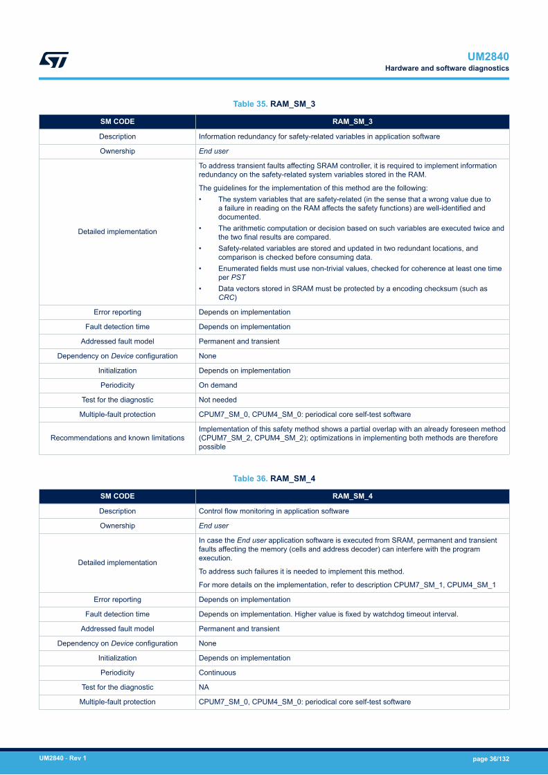
Table 35. RAM_SM_3
SM CODE RAM_SM_3
Description Information redundancy for safety-related variables in application software
Ownership End user
Detailed implementation
To address transient faults affecting SRAM controller, it is required to implement informationredundancy on the safety-related system variables stored in the RAM.
The guidelines for the implementation of this method are the following:• The system variables that are safety-related (in the sense that a wrong value due to
a failure in reading on the RAM affects the safety functions) are well-identified anddocumented.
• The arithmetic computation or decision based on such variables are executed twice andthe two final results are compared.
• Safety-related variables are stored and updated in two redundant locations, andcomparison is checked before consuming data.
• Enumerated fields must use non-trivial values, checked for coherence at least one timeper PST
• Data vectors stored in SRAM must be protected by a encoding checksum (such asCRC)
Error reporting Depends on implementation
Fault detection time Depends on implementation
Addressed fault model Permanent and transient
Dependency on Device configuration None
Initialization Depends on implementation
Periodicity On demand
Test for the diagnostic Not needed
Multiple-fault protection CPUM7_SM_0, CPUM4_SM_0: periodical core self-test software
Recommendations and known limitationsImplementation of this safety method shows a partial overlap with an already foreseen method(CPUM7_SM_2, CPUM4_SM_2); optimizations in implementing both methods are thereforepossible
Table 36. RAM_SM_4
SM CODE RAM_SM_4
Description Control flow monitoring in application software
Ownership End user
Detailed implementation
In case the End user application software is executed from SRAM, permanent and transientfaults affecting the memory (cells and address decoder) can interfere with the programexecution.
To address such failures it is needed to implement this method.
For more details on the implementation, refer to description CPUM7_SM_1, CPUM4_SM_1
Error reporting Depends on implementation
Fault detection time Depends on implementation. Higher value is fixed by watchdog timeout interval.
Addressed fault model Permanent and transient
Dependency on Device configuration None
Initialization Depends on implementation
Periodicity Continuous
Test for the diagnostic NA
Multiple-fault protection CPUM7_SM_0, CPUM4_SM_0: periodical core self-test software
UM2840Hardware and software diagnostics
UM2840 - Rev 1 page 36/132
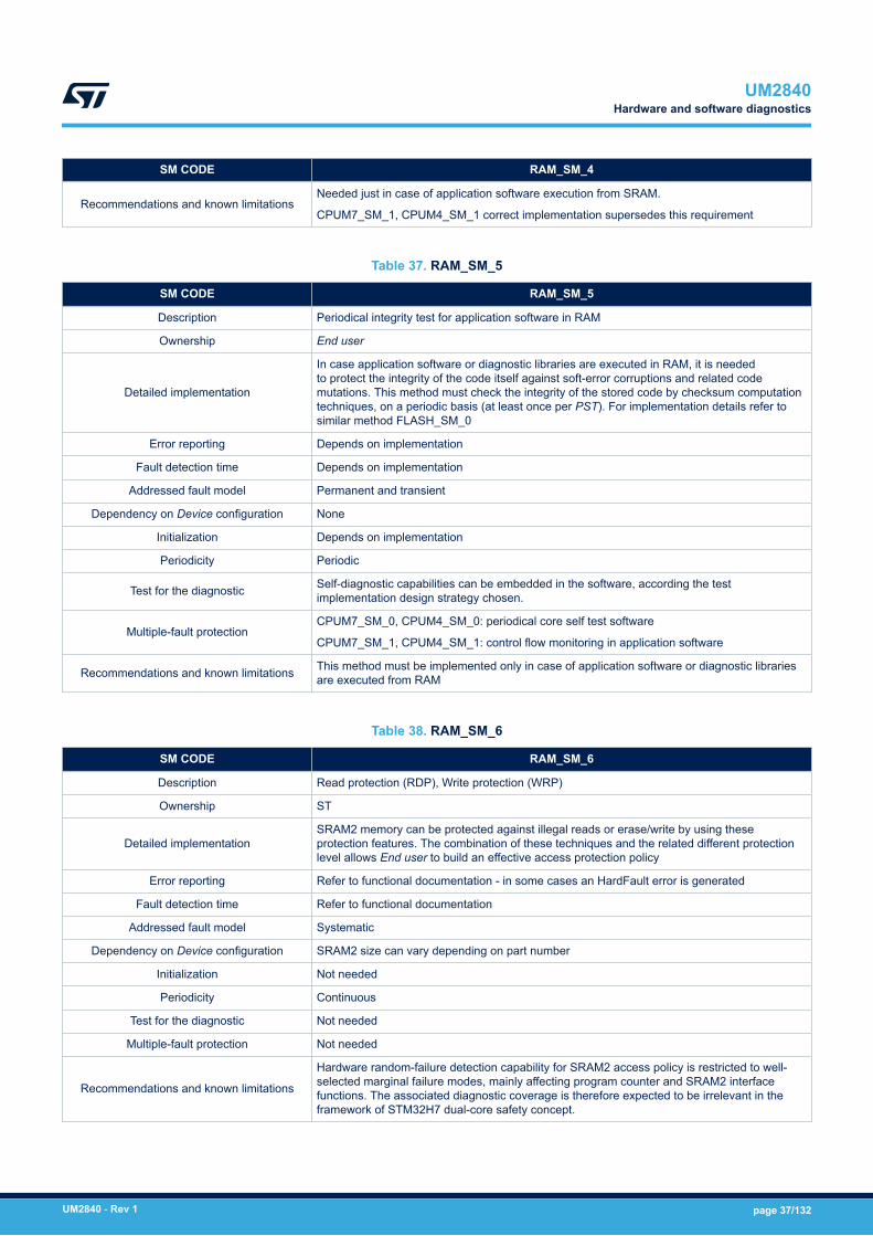
SM CODE RAM_SM_4
Recommendations and known limitationsNeeded just in case of application software execution from SRAM.
CPUM7_SM_1, CPUM4_SM_1 correct implementation supersedes this requirement
Table 37. RAM_SM_5
SM CODE RAM_SM_5
Description Periodical integrity test for application software in RAM
Ownership End user
Detailed implementation
In case application software or diagnostic libraries are executed in RAM, it is neededto protect the integrity of the code itself against soft-error corruptions and related codemutations. This method must check the integrity of the stored code by checksum computationtechniques, on a periodic basis (at least once per PST). For implementation details refer tosimilar method FLASH_SM_0
Error reporting Depends on implementation
Fault detection time Depends on implementation
Addressed fault model Permanent and transient
Dependency on Device configuration None
Initialization Depends on implementation
Periodicity Periodic
Test for the diagnostic Self-diagnostic capabilities can be embedded in the software, according the testimplementation design strategy chosen.
Multiple-fault protectionCPUM7_SM_0, CPUM4_SM_0: periodical core self test software
CPUM7_SM_1, CPUM4_SM_1: control flow monitoring in application software
Recommendations and known limitations This method must be implemented only in case of application software or diagnostic librariesare executed from RAM
Table 38. RAM_SM_6
SM CODE RAM_SM_6
Description Read protection (RDP), Write protection (WRP)
Ownership ST
Detailed implementationSRAM2 memory can be protected against illegal reads or erase/write by using theseprotection features. The combination of these techniques and the related different protectionlevel allows End user to build an effective access protection policy
Error reporting Refer to functional documentation - in some cases an HardFault error is generated
Fault detection time Refer to functional documentation
Addressed fault model Systematic
Dependency on Device configuration SRAM2 size can vary depending on part number
Initialization Not needed
Periodicity Continuous
Test for the diagnostic Not needed
Multiple-fault protection Not needed
Recommendations and known limitations
Hardware random-failure detection capability for SRAM2 access policy is restricted to well-selected marginal failure modes, mainly affecting program counter and SRAM2 interfacefunctions. The associated diagnostic coverage is therefore expected to be irrelevant in theframework of STM32H7 dual-core safety concept.
UM2840Hardware and software diagnostics
UM2840 - Rev 1 page 37/132

Table 39. RAM_SM_7
SM CODE RAM_SM_7
Description ECC on SRAM
Ownership ST
Detailed implementation
Internal SRAM is protected by an ECC (Error Correction Code)redundancy implementing a protection feature at double-word (64 bit)level:• One bit fault: correction• Two bits fault: detection
Error reporting Refer to functional documentation
Fault detection time ECC bits are checked during a memory reading
Addressed fault model Permanent/Transient
Dependency on Device configuration None
Initialization None
Periodicity Continuous
Test for the diagnostic Not needed
Multiple-fault protection• RAM_SM_0: Periodical software test for Flash memory• DIAG_SM_0: Periodical read-back of hardware diagnostics
configuration registers
Recommendations and known limitations The FMEDA snapshot document [2] includes information onrecommended frequency for RAM_SM_0.
Table 40. RAM_SM_8
SM CODE RAM_SM_8
Description Periodic test by software for SRAM address decoder
Ownership ST or End user
Detailed implementationPermanent faults affecting the SRAM interfaces address decoder areaddressed through a dedicated software test that checks the memorycells contents versus the expected value.
Error reporting Depends on implementation
Fault detection time Depends on implementation
Addressed fault model Permanent
Dependency on Device configuration SRAM size varies according to part number
Initialization Not needed
Periodicity Periodical
Test for the diagnostic Not needed
Multiple-fault protection CPUM7_SM_0, CPUM4_SM_0: Periodical core self test software
Recommendations and known limitations Overlaps with RAM_SM_0 implementation are possible.
3.6.6 System bus architecture/peripherals interconnect matrix
Table 41. BUS_SM_0
SM CODE BUS_SM_0
Description Periodical software test for interconnections
UM2840Hardware and software diagnostics
UM2840 - Rev 1 page 38/132
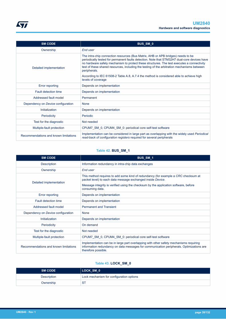
SM CODE BUS_SM_0
Ownership End user
Detailed implementation
The intra-chip connection resources (Bus Matrix, AHB or APB bridges) needs to beperiodically tested for permanent faults detection. Note that STM32H7 dual-core devices haveno hardware safety mechanism to protect these structures. The test executes a connectivitytest of these shared resources, including the testing of the arbitration mechanisms betweenperipherals.
According to IEC 61508-2 Table A.8, A.7.4 the method is considered able to achieve highlevels of coverage
Error reporting Depends on implementation
Fault detection time Depends on implementation
Addressed fault model Permanent
Dependency on Device configuration None
Initialization Depends on implementation
Periodicity Periodic
Test for the diagnostic Not needed
Multiple-fault protection CPUM7_SM_0, CPUM4_SM_0: periodical core self-test software
Recommendations and known limitations Implementation can be considered in large part as overlapping with the widely used Periodicalread-back of configuration registers required for several peripherals
Table 42. BUS_SM_1
SM CODE BUS_SM_1
Description Information redundancy in intra-chip data exchanges
Ownership End user
Detailed implementation
This method requires to add some kind of redundancy (for example a CRC checksum atpacket level) to each data message exchanged inside Device.
Message integrity is verified using the checksum by the application software, beforeconsuming data.
Error reporting Depends on implementation
Fault detection time Depends on implementation
Addressed fault model Permanent and Transient
Dependency on Device configuration None
Initialization Depends on implementation
Periodicity On demand
Test for the diagnostic Not needed
Multiple-fault protection CPUM7_SM_0, CPUM4_SM_0: periodical core self-test software
Recommendations and known limitationsImplementation can be in large part overlapping with other safety mechanisms requiringinformation redundancy on data messages for communication peripherals. Optimizations aretherefore possible.
Table 43. LOCK_SM_0
SM CODE LOCK_SM_0
Description Lock mechanism for configuration options
Ownership ST
UM2840Hardware and software diagnostics
UM2840 - Rev 1 page 39/132
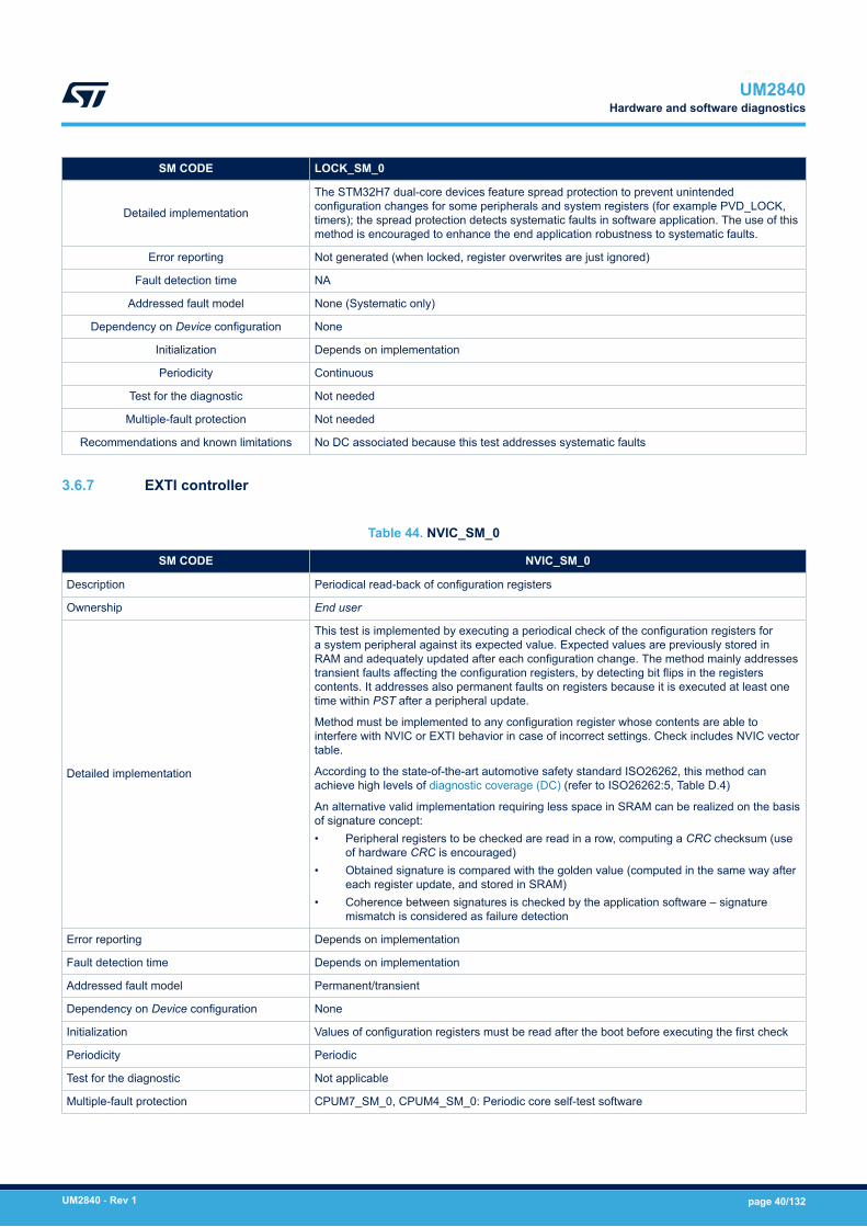
SM CODE LOCK_SM_0
Detailed implementation
The STM32H7 dual-core devices feature spread protection to prevent unintendedconfiguration changes for some peripherals and system registers (for example PVD_LOCK,timers); the spread protection detects systematic faults in software application. The use of thismethod is encouraged to enhance the end application robustness to systematic faults.
Error reporting Not generated (when locked, register overwrites are just ignored)
Fault detection time NA
Addressed fault model None (Systematic only)
Dependency on Device configuration None
Initialization Depends on implementation
Periodicity Continuous
Test for the diagnostic Not needed
Multiple-fault protection Not needed
Recommendations and known limitations No DC associated because this test addresses systematic faults
3.6.7 EXTI controller
Table 44. NVIC_SM_0
SM CODE NVIC_SM_0
Description Periodical read-back of configuration registers
Ownership End user
Detailed implementation
This test is implemented by executing a periodical check of the configuration registers fora system peripheral against its expected value. Expected values are previously stored inRAM and adequately updated after each configuration change. The method mainly addressestransient faults affecting the configuration registers, by detecting bit flips in the registerscontents. It addresses also permanent faults on registers because it is executed at least onetime within PST after a peripheral update.
Method must be implemented to any configuration register whose contents are able tointerfere with NVIC or EXTI behavior in case of incorrect settings. Check includes NVIC vectortable.
According to the state-of-the-art automotive safety standard ISO26262, this method canachieve high levels of diagnostic coverage (DC) (refer to ISO26262:5, Table D.4)
An alternative valid implementation requiring less space in SRAM can be realized on the basisof signature concept:• Peripheral registers to be checked are read in a row, computing a CRC checksum (use
of hardware CRC is encouraged)• Obtained signature is compared with the golden value (computed in the same way after
each register update, and stored in SRAM)• Coherence between signatures is checked by the application software – signature
mismatch is considered as failure detection
Error reporting Depends on implementation
Fault detection time Depends on implementation
Addressed fault model Permanent/transient
Dependency on Device configuration None
Initialization Values of configuration registers must be read after the boot before executing the first check
Periodicity Periodic
Test for the diagnostic Not applicable
Multiple-fault protection CPUM7_SM_0, CPUM4_SM_0: Periodic core self-test software
UM2840Hardware and software diagnostics
UM2840 - Rev 1 page 40/132

SM CODE NVIC_SM_0
Recommendations and known limitations
This method addresses only failures affecting configuration registers, and not peripheral corelogic or external interface.
Attention must be paid to registers containing mixed combination of configuration and statusbits. Mask must be used before saving register contents affecting signature, and relatedchecks, to avoid false positive detections.
Table 45. NVIC_SM_1
SM CODE NVIC_SM_1
Description Expected and unexpected interrupt check
Ownership End user
Detailed implementation
According to IEC 61508-2 Table A.1 recommendations, a diagnostic measure for continuous,absence or cross-over of interrupt must be implemented. The method of expected andunexpected interrupt check is implemented at application software level.
The guidelines for the implementation of the method are the following:• The interrupts implemented on the MCU are well documented, also reporting, when
possible, the expected frequency of each request (for example, the interrupts related toADC conversion completion that come on a regular basis).
• Individual counters are maintained for each interrupt request served, in order to detect ina given time frame the cases of a) no interrupt at all b) too many interrupt requests(“babbling idiot” interrupt source). The control of the time frame duration must beregulated according to the individual interrupt expected frequency.
• Interrupt vectors related to unused interrupt source point to a default handler thatreports, in case of triggering, a faulty condition (unexpected interrupt).
• In case an interrupt service routine is shared between different sources, a plausibilitycheck on the caller identity is implemented.
• Interrupt requests related to non-safety-related peripherals are handled with the samemethod here described, despite their originator safety classification
Error reporting Depends on implementation
Fault detection time Depends on implementation
Addressed fault model Permanent/transient
Dependency on Device configuration None
Initialization Depends on implementation
Periodicity Continuous
Test for the diagnostic Not applicable
Multiple-fault protection CPUM7_SM_0, CPUM4_SM_0: Periodic core selft-test software
Recommendations and known limitations In order to decrease the complexity of method implementation, it is suggested to use pollingtechnique (when possible) instead of interrupt for end system implementation
UM2840Hardware and software diagnostics
UM2840 - Rev 1 page 41/132

3.6.8 Direct memory access controllers (DMA, MDMA, BDMA and DMA request multiplexer(DMAMUX))
Table 46. DMA_SM_0
SM CODE DMA_SM_0
Description Periodical read-back of configuration registers
Ownership End user
Detailed implementation
This method must be applied to DMA configuration register and channel addresses register aswell.
Detailed information on the implementation of this method can be found inSection 3.6.7 EXTI controller
Error reporting Refer to NVIC_SM_0
Fault detection time Refer to NVIC_SM_0
Addressed fault model Refer to NVIC_SM_0
Dependency on Device configuration Refer to NVIC_SM_0
Initialization Refer to NVIC_SM_0
Periodicity Refer to NVIC_SM_0
Test for the diagnostic Refer to NVIC_SM_0
Multiple-fault protection Refer to NVIC_SM_0
Recommendations and known limitations Refer to NVIC_SM_0
Table 47. DMA_SM_1
SM CODE DMA_SM_1
Description Information redundancy on data packet transferred via DMA
Ownership End user
Detailed implementation
This method is implemented adding to data packets transferred by DMA a redundancy check(such as CRC check, or similar one) with encoding capability. Full data packet redundancywould be overkilling.
The checksum encoding capability must be robust enough to guarantee at least 90%probability of detection for a single bit flip and multi-bits flip in the data packet
Consistency of data packet must be checked by the application software before consumingdata
Error reporting Depends on implementation
Fault detection time Depends on implementation
Addressed fault model Permanent and transient
Dependency on Device configuration None
Initialization Depends on implementation
Periodicity On demand
Test for the diagnostic Not needed
Multiple-fault protection CPUM7_SM_0, CPUM4_SM_0: periodical core self-test software
Recommendations and known limitations To give an example about checksum encoding capability, using just a bit-by-bit addition isunappropriated
UM2840Hardware and software diagnostics
UM2840 - Rev 1 page 42/132
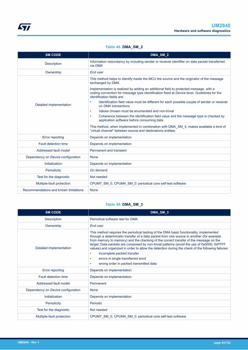
Table 48. DMA_SM_2
SM CODE DMA_SM_2
Description Information redundancy by including sender or receiver identifier on data packet transferredvia DMA
Ownership End user
Detailed implementation
This method helps to identify inside the MCU the source and the originator of the messageexchanged by DMA.
Implementation is realized by adding an additional field to protected message, with acoding convention for message type identification fixed at Device level. Guidelines for theidentification fields are:• Identification field value must be different for each possible couple of sender or receiver
on DMA transactions• Values chosen must be enumerated and non-trivial• Coherence between the identification field value and the message type is checked by
application software before consuming data.
This method, when implemented in combination with DMA_SM_4, makes available a kind of“virtual channel” between source and destinations entities.
Error reporting Depends on implementation
Fault detection time Depends on implementation
Addressed fault model Permanent and transient
Dependency on Device configuration None
Initialization Depends on implementation
Periodicity On demand
Test for the diagnostic Not needed
Multiple-fault protection CPUM7_SM_0, CPUM4_SM_0: periodical core self-test software
Recommendations and known limitations None
Table 49. DMA_SM_3
SM CODE DMA_SM_3
Description Periodical software test for DMA
Ownership End user
Detailed implementation
This method requires the periodical testing of the DMA basic functionality, implementedthrough a deterministic transfer of a data packet from one source to another (for examplefrom memory to memory) and the checking of the correct transfer of the message on thetarget. Data packets are composed by non-trivial patterns (avoid the use of 0x0000, 0xFFFFvalues) and organized in order to allow the detection during the check of the following failures:• incomplete packed transfer• errors in single transferred word• wrong order in packed transmitted data
Error reporting Depends on implementation
Fault detection time Depends on implementation
Addressed fault model Permanent
Dependency on Device configuration None
Initialization Depends on implementation
Periodicity Periodic
Test for the diagnostic Not needed
Multiple-fault protection CPUM7_SM_0, CPUM4_SM_0: periodical core self-test software
UM2840Hardware and software diagnostics
UM2840 - Rev 1 page 43/132

SM CODE DMA_SM_3
Recommendations and known limitations None
Table 50. DMA_SM_4
SM CODE DMA_SM_4
Description DMA transaction awareness
Ownership End user
Detailed implementation
DMA transactions are non-deterministic by nature, because typically driven by external eventslike communication messages reception. Anyway, well-designed safety systems should keepmuch control as possible of events – refer for instance to IEC 61508-3 Table 2 item 13requirements for software architecture.
This method is based on system knowledge of frequency and type of expected DMAtransaction. For instance, an externally connected sensor supposed to send periodically somemessages to a STM32 peripheral. Monitoring DMA transaction by a dedicated state machineallows to detect missing or unexpected DMA activities.
Error reporting Depends on implementation
Fault detection time Depends on implementation
Addressed fault model Permanent and transient
Dependency on Device configuration None
Initialization Depends on implementation
Periodicity Continuous
Test for the diagnostic Not needed
Multiple-fault protection CPUM7_SM_0, CPUM4_SM_0: periodical core self-test software
Recommendations and known limitationsBecause DMA transaction termination is often linked to an interrupt generation,implementation of this method can be merged with the safety mechanism NVIC_SM_1:expected and unexpected interrupt check.
3.6.9 Chrom-Art Accelerator controller (DMA2D)
Table 51. DMA2D_SM_0
SM CODE DMA2D_SM_0
Description Periodical read-back of configuration registers
Ownership End user
Detailed implementationThis method must be applied to DMA2D configuration registers.
Detailed information on the implementation of this method can be foundin Section 3.6.7 EXTI controller
Error reporting Refer to NVIC_SM_0
Fault detection time Refer to NVIC_SM_0
Addressed fault model Refer to NVIC_SM_0
Dependency on Device configuration Refer to NVIC_SM_0
Initialization Refer to NVIC_SM_0
Periodicity Refer to NVIC_SM_0
Test for the diagnostic Refer to NVIC_SM_0
Multiple-fault protection Refer to NVIC_SM_0
Recommendations and known limitations Refer to NVIC_SM_0
UM2840Hardware and software diagnostics
UM2840 - Rev 1 page 44/132
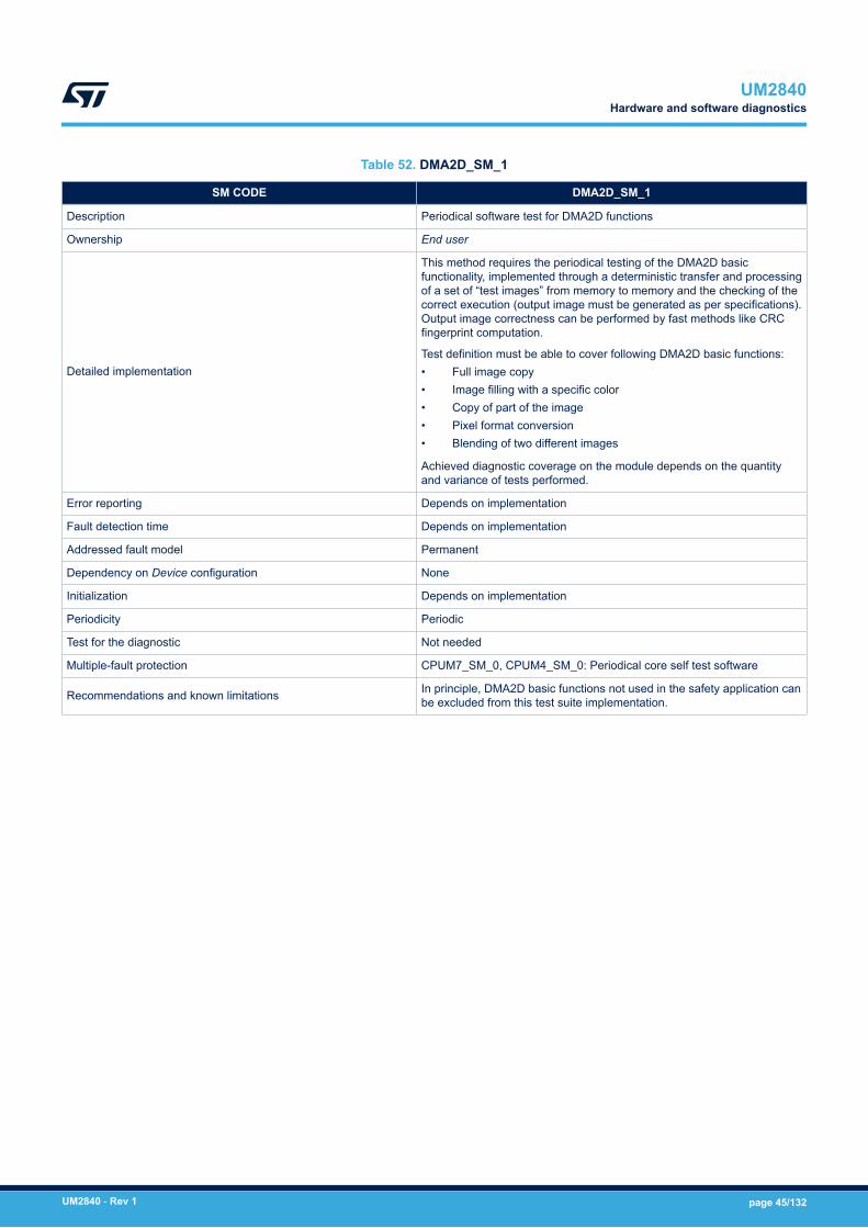
Table 52. DMA2D_SM_1
SM CODE DMA2D_SM_1
Description Periodical software test for DMA2D functions
Ownership End user
Detailed implementation
This method requires the periodical testing of the DMA2D basicfunctionality, implemented through a deterministic transfer and processingof a set of “test images” from memory to memory and the checking of thecorrect execution (output image must be generated as per specifications).Output image correctness can be performed by fast methods like CRCfingerprint computation.
Test definition must be able to cover following DMA2D basic functions:• Full image copy• Image filling with a specific color• Copy of part of the image• Pixel format conversion• Blending of two different images
Achieved diagnostic coverage on the module depends on the quantityand variance of tests performed.
Error reporting Depends on implementation
Fault detection time Depends on implementation
Addressed fault model Permanent
Dependency on Device configuration None
Initialization Depends on implementation
Periodicity Periodic
Test for the diagnostic Not needed
Multiple-fault protection CPUM7_SM_0, CPUM4_SM_0: Periodical core self test software
Recommendations and known limitations In principle, DMA2D basic functions not used in the safety application canbe excluded from this test suite implementation.
UM2840Hardware and software diagnostics
UM2840 - Rev 1 page 45/132
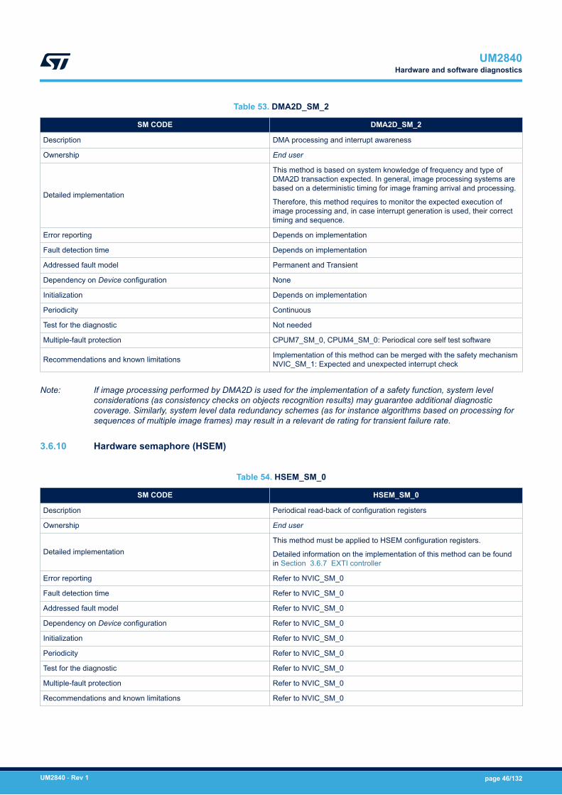
Table 53. DMA2D_SM_2
SM CODE DMA2D_SM_2
Description DMA processing and interrupt awareness
Ownership End user
Detailed implementation
This method is based on system knowledge of frequency and type ofDMA2D transaction expected. In general, image processing systems arebased on a deterministic timing for image framing arrival and processing.
Therefore, this method requires to monitor the expected execution ofimage processing and, in case interrupt generation is used, their correcttiming and sequence.
Error reporting Depends on implementation
Fault detection time Depends on implementation
Addressed fault model Permanent and Transient
Dependency on Device configuration None
Initialization Depends on implementation
Periodicity Continuous
Test for the diagnostic Not needed
Multiple-fault protection CPUM7_SM_0, CPUM4_SM_0: Periodical core self test software
Recommendations and known limitations Implementation of this method can be merged with the safety mechanismNVIC_SM_1: Expected and unexpected interrupt check
Note: If image processing performed by DMA2D is used for the implementation of a safety function, system levelconsiderations (as consistency checks on objects recognition results) may guarantee additional diagnosticcoverage. Similarly, system level data redundancy schemes (as for instance algorithms based on processing forsequences of multiple image frames) may result in a relevant de rating for transient failure rate.
3.6.10 Hardware semaphore (HSEM)
Table 54. HSEM_SM_0
SM CODE HSEM_SM_0
Description Periodical read-back of configuration registers
Ownership End user
Detailed implementationThis method must be applied to HSEM configuration registers.
Detailed information on the implementation of this method can be foundin Section 3.6.7 EXTI controller
Error reporting Refer to NVIC_SM_0
Fault detection time Refer to NVIC_SM_0
Addressed fault model Refer to NVIC_SM_0
Dependency on Device configuration Refer to NVIC_SM_0
Initialization Refer to NVIC_SM_0
Periodicity Refer to NVIC_SM_0
Test for the diagnostic Refer to NVIC_SM_0
Multiple-fault protection Refer to NVIC_SM_0
Recommendations and known limitations Refer to NVIC_SM_0
UM2840Hardware and software diagnostics
UM2840 - Rev 1 page 46/132

Table 55. HSEM_SM_1
SM CODE HSEM_SM_1
Description Control flow monitoring for concurrent tasks
Ownership End user
Detailed implementation
This method is intended to monitor the correct execution of softwaretasks that use the HSEM semaphore method for their synchronization.Method is implemented by software, leveraging on the presence of asystem watchdog (internal or external).
Watchdog periodic reset function must be constrained to the correcttiming execution of each software task synchronized by semaphores.
Error reporting Depends on implementation
Fault detection time Depends on implementation. Higher value is fixed by watchdog timeoutinterval.
Addressed fault model Permanent and Transient
Dependency on Device configuration None
Initialization Depends on implementation
Periodicity Continuous
Test for the diagnostic N/A
Multiple-fault protection CPUM7_SM_0, CPUM4_SM_0: Periodical core self test software
Recommendations and known limitations Implementation must take into account potential overlaps/optimizationswith CPUM7_SM_1, CPUM4_SM_1.
3.6.11 Single Wire Protocol Master Interface (SWPMI)
Table 56. SWPMI_SM_0
SM CODE SWPMI_SM_0
Description Periodical read-back of configuration registers
Ownership End user
Detailed implementationThis method must be applied to SWPMI configuration registers.
Detailed information on the implementation of this method can be foundin Section 3.6.7 EXTI controller
Error reporting Refer to NVIC_SM_0
Fault detection time Refer to NVIC_SM_0
Addressed fault model Refer to NVIC_SM_0
Dependency on Device configuration Refer to NVIC_SM_0
Initialization Refer to NVIC_SM_0
Periodicity Refer to NVIC_SM_0
Test for the diagnostic Refer to NVIC_SM_0
Multiple-fault protection Refer to NVIC_SM_0
Recommendations and known limitations Refer to NVIC_SM_0
UM2840Hardware and software diagnostics
UM2840 - Rev 1 page 47/132
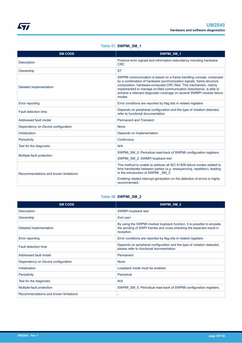
Table 57. SWPMI_SM_1
SM CODE SWPMI_SM_1
Description Protocol error signals and information redundancy including hardwareCRC
Ownership ST
Detailed implementation
SWPMI communication is based on a frame handling concept, composedby a combination of hardware synchronization signals, frame structurecomposition, hardware-computed CRC filed. This mechanism, mainlyimplemented to manage on-field communication disturbance, is able toachieve a relevant diagnostic coverage on several SWMPI module failuremodes.
Error reporting Error conditions are reported by flag bits in related registers
Fault detection time Depends on peripheral configuration and the type of violation detected,refer to functional documentation
Addressed fault model Permanent and Transient
Dependency on Device configuration None
Initialization Depends on implementation
Periodicity Continuous
Test for the diagnostic N/A
Multiple-fault protectionSWPMI_SM_0: Periodical read-back of SWPMI configuration registers.
SWPMI_SM_2: SWMPI loopback test
Recommendations and known limitations
This method is unable to address all IEC 61508 failure modes related totime handshake between parties (e.g. resequencing, repetition), leadingto the introduction of SWPMI _SM_3.
Enabling related interrupt generation on the detection of errors is highlyrecommended.
Table 58. SWPMI_SM_2
SM CODE SWPMI_SM_2
Description SWMPI loopback test
Ownership End user
Detailed implementationBy using the SWPMI module loopback function, it is possible to emulatethe sending of SWPI frames and cross-checking the expected result inreception.
Error reporting Error conditions are reported by flag bits in related registers
Fault detection time Depends on peripheral configuration and the type of violation detected,please refer to functional documentation
Addressed fault model Permanent
Dependency on Device configuration None
Initialization Loopback mode must be enabled
Periodicity Periodical
Test for the diagnostic N/A
Multiple-fault protection SWPMI_SM_0: Periodical read-back of SWPMI configuration registers.
Recommendations and known limitations -
UM2840Hardware and software diagnostics
UM2840 - Rev 1 page 48/132
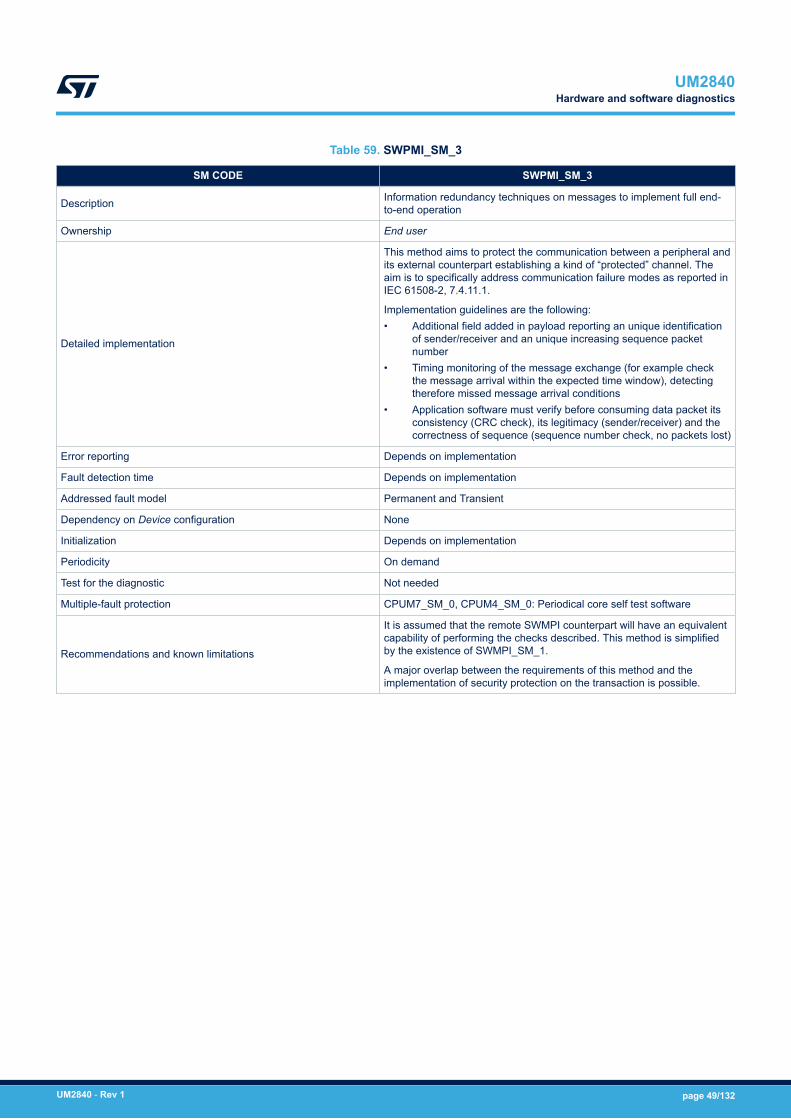
Table 59. SWPMI_SM_3
SM CODE SWPMI_SM_3
Description Information redundancy techniques on messages to implement full end-to-end operation
Ownership End user
Detailed implementation
This method aims to protect the communication between a peripheral andits external counterpart establishing a kind of “protected” channel. Theaim is to specifically address communication failure modes as reported inIEC 61508-2, 7.4.11.1.
Implementation guidelines are the following:• Additional field added in payload reporting an unique identification
of sender/receiver and an unique increasing sequence packetnumber
• Timing monitoring of the message exchange (for example checkthe message arrival within the expected time window), detectingtherefore missed message arrival conditions
• Application software must verify before consuming data packet itsconsistency (CRC check), its legitimacy (sender/receiver) and thecorrectness of sequence (sequence number check, no packets lost)
Error reporting Depends on implementation
Fault detection time Depends on implementation
Addressed fault model Permanent and Transient
Dependency on Device configuration None
Initialization Depends on implementation
Periodicity On demand
Test for the diagnostic Not needed
Multiple-fault protection CPUM7_SM_0, CPUM4_SM_0: Periodical core self test software
Recommendations and known limitations
It is assumed that the remote SWMPI counterpart will have an equivalentcapability of performing the checks described. This method is simplifiedby the existence of SWMPI_SM_1.
A major overlap between the requirements of this method and theimplementation of security protection on the transaction is possible.
UM2840Hardware and software diagnostics
UM2840 - Rev 1 page 49/132
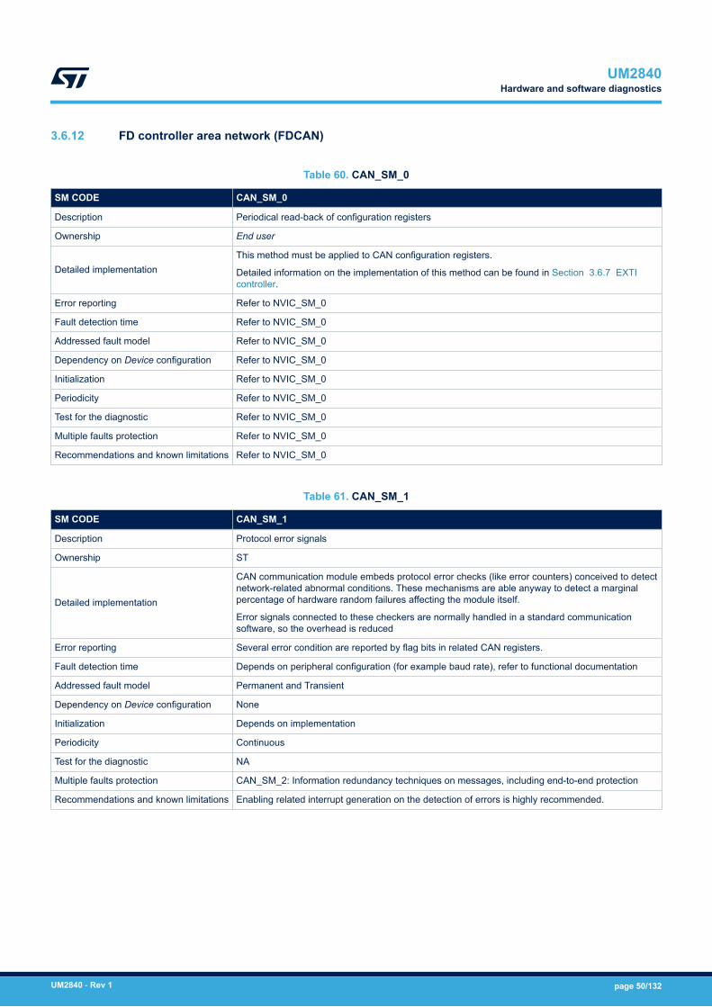
3.6.12 FD controller area network (FDCAN)
Table 60. CAN_SM_0
SM CODE CAN_SM_0
Description Periodical read-back of configuration registers
Ownership End user
Detailed implementationThis method must be applied to CAN configuration registers.
Detailed information on the implementation of this method can be found in Section 3.6.7 EXTIcontroller.
Error reporting Refer to NVIC_SM_0
Fault detection time Refer to NVIC_SM_0
Addressed fault model Refer to NVIC_SM_0
Dependency on Device configuration Refer to NVIC_SM_0
Initialization Refer to NVIC_SM_0
Periodicity Refer to NVIC_SM_0
Test for the diagnostic Refer to NVIC_SM_0
Multiple faults protection Refer to NVIC_SM_0
Recommendations and known limitations Refer to NVIC_SM_0
Table 61. CAN_SM_1
SM CODE CAN_SM_1
Description Protocol error signals
Ownership ST
Detailed implementation
CAN communication module embeds protocol error checks (like error counters) conceived to detectnetwork-related abnormal conditions. These mechanisms are able anyway to detect a marginalpercentage of hardware random failures affecting the module itself.
Error signals connected to these checkers are normally handled in a standard communicationsoftware, so the overhead is reduced
Error reporting Several error condition are reported by flag bits in related CAN registers.
Fault detection time Depends on peripheral configuration (for example baud rate), refer to functional documentation
Addressed fault model Permanent and Transient
Dependency on Device configuration None
Initialization Depends on implementation
Periodicity Continuous
Test for the diagnostic NA
Multiple faults protection CAN_SM_2: Information redundancy techniques on messages, including end-to-end protection
Recommendations and known limitations Enabling related interrupt generation on the detection of errors is highly recommended.
UM2840Hardware and software diagnostics
UM2840 - Rev 1 page 50/132

Table 62. CAN_SM_2
SM CODE CAN_SM_2
Description Information redundancy techniques on messages, including end-to-end protection.
Ownership End user
Detailed implementation
This method aims to protect the communication between a peripheral and his external counterpart establishinga kind of “protected” channel. The aim is to specifically address communication failure modes as reported inIEC 61508-2, 7.4.11.1.
Implementation guidelines are the following:• Data packet must be protected (encapsulated) by an information redundancy check, like for instance a
CRC checksum computed over the packet and added to payload. Checksum encoding capability mustbe robust enough to guarantee at least 90% probability of detection for a single bit flip and multi-bits flipin the data packet.
• Additional field added in payload reporting an unique identification of sender or receiver and an uniqueincreasing sequence packet number
• Timing monitoring of the message exchange (for example check the message arrival within the expectedtime window), detecting therefore missed message arrival conditions
• Application software must verify before consuming data packet its consistency (CRC check), itslegitimacy (sender or receiver) and the sequence correctness (sequence number check, no packetslost)
Error reporting Depends on implementation
Fault detection time Depends on implementation
Addressed fault model Permanent and Transient
Dependency on Deviceconfiguration None
Initialization Depends on implementation
Periodicity On demand
Test for the diagnostic Not needed
Multiple faults protection CPUM7_SM_0, CPUM4_SM_0: periodical core self-test software
Recommendations andknown limitations
Important note: it is assumed that the remote CAN counterpart has an equivalent capability of performing thechecks described.
A major overlap between the requirements of this method and the implementation of complex communicationsoftware protocols can exists. Due to large adoption of these protocols in industrial applications, optimizationscan be possible
3.6.13 Universal synchronous/asynchronous receiver/transmitter (USART 1/2/3/4/5/6/7/8, LPUART1)
Table 63. UART_SM_0
SM CODE UART_SM_0
Description Periodical read-back of configuration registers
Ownership End user
Detailed implementationThis method must be applied to UART configuration registers.
Detailed information on the implementation of this method can be found inSection 3.6.7 EXTI controller.
Error reporting Refer to NVIC_SM_0
Fault detection time Refer to NVIC_SM_0
Addressed fault model Refer to NVIC_SM_0
Dependency on Device configuration Refer to NVIC_SM_0
Initialization Refer to NVIC_SM_0
UM2840Hardware and software diagnostics
UM2840 - Rev 1 page 51/132
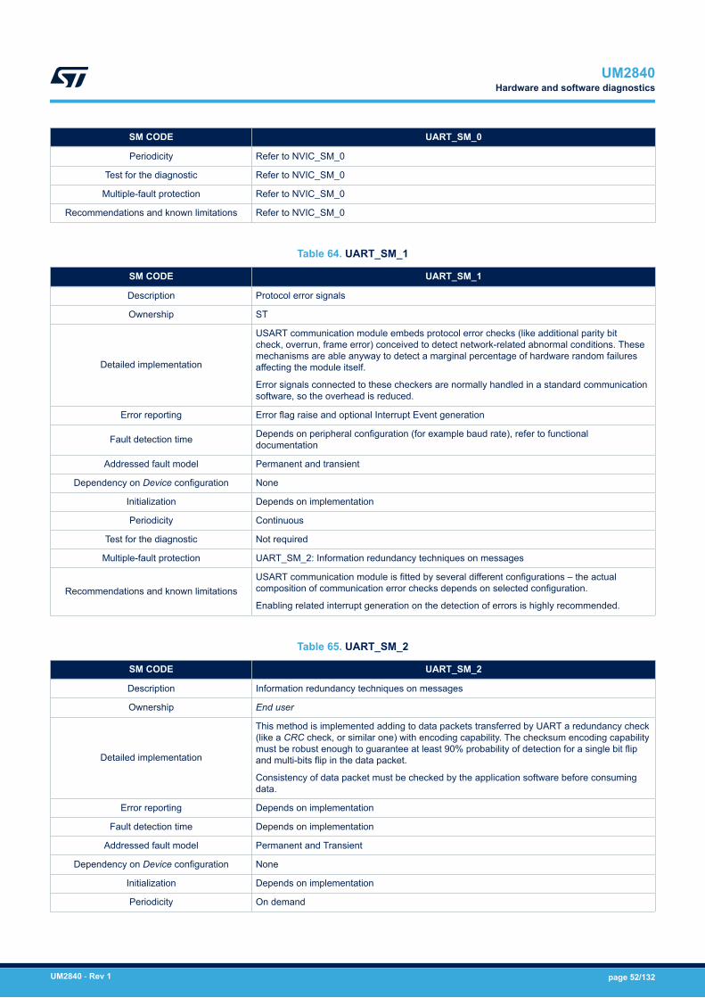
SM CODE UART_SM_0
Periodicity Refer to NVIC_SM_0
Test for the diagnostic Refer to NVIC_SM_0
Multiple-fault protection Refer to NVIC_SM_0
Recommendations and known limitations Refer to NVIC_SM_0
Table 64. UART_SM_1
SM CODE UART_SM_1
Description Protocol error signals
Ownership ST
Detailed implementation
USART communication module embeds protocol error checks (like additional parity bitcheck, overrun, frame error) conceived to detect network-related abnormal conditions. Thesemechanisms are able anyway to detect a marginal percentage of hardware random failuresaffecting the module itself.
Error signals connected to these checkers are normally handled in a standard communicationsoftware, so the overhead is reduced.
Error reporting Error flag raise and optional Interrupt Event generation
Fault detection time Depends on peripheral configuration (for example baud rate), refer to functionaldocumentation
Addressed fault model Permanent and transient
Dependency on Device configuration None
Initialization Depends on implementation
Periodicity Continuous
Test for the diagnostic Not required
Multiple-fault protection UART_SM_2: Information redundancy techniques on messages
Recommendations and known limitationsUSART communication module is fitted by several different configurations – the actualcomposition of communication error checks depends on selected configuration.
Enabling related interrupt generation on the detection of errors is highly recommended.
Table 65. UART_SM_2
SM CODE UART_SM_2
Description Information redundancy techniques on messages
Ownership End user
Detailed implementation
This method is implemented adding to data packets transferred by UART a redundancy check(like a CRC check, or similar one) with encoding capability. The checksum encoding capabilitymust be robust enough to guarantee at least 90% probability of detection for a single bit flipand multi-bits flip in the data packet.
Consistency of data packet must be checked by the application software before consumingdata.
Error reporting Depends on implementation
Fault detection time Depends on implementation
Addressed fault model Permanent and Transient
Dependency on Device configuration None
Initialization Depends on implementation
Periodicity On demand
UM2840Hardware and software diagnostics
UM2840 - Rev 1 page 52/132
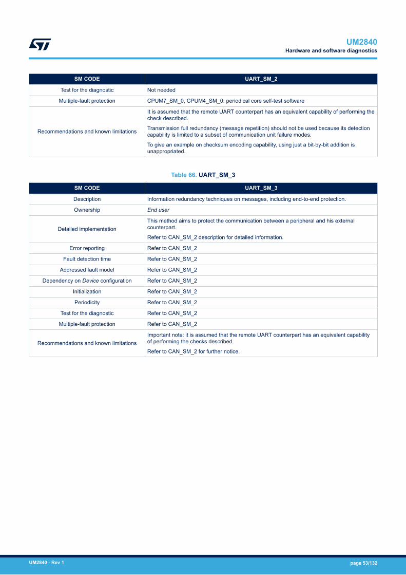
SM CODE UART_SM_2
Test for the diagnostic Not needed
Multiple-fault protection CPUM7_SM_0, CPUM4_SM_0: periodical core self-test software
Recommendations and known limitations
It is assumed that the remote UART counterpart has an equivalent capability of performing thecheck described.
Transmission full redundancy (message repetition) should not be used because its detectioncapability is limited to a subset of communication unit failure modes.
To give an example on checksum encoding capability, using just a bit-by-bit addition isunappropriated.
Table 66. UART_SM_3
SM CODE UART_SM_3
Description Information redundancy techniques on messages, including end-to-end protection.
Ownership End user
Detailed implementationThis method aims to protect the communication between a peripheral and his externalcounterpart.
Refer to CAN_SM_2 description for detailed information.
Error reporting Refer to CAN_SM_2
Fault detection time Refer to CAN_SM_2
Addressed fault model Refer to CAN_SM_2
Dependency on Device configuration Refer to CAN_SM_2
Initialization Refer to CAN_SM_2
Periodicity Refer to CAN_SM_2
Test for the diagnostic Refer to CAN_SM_2
Multiple-fault protection Refer to CAN_SM_2
Recommendations and known limitationsImportant note: it is assumed that the remote UART counterpart has an equivalent capabilityof performing the checks described.
Refer to CAN_SM_2 for further notice.
UM2840Hardware and software diagnostics
UM2840 - Rev 1 page 53/132

3.6.14 Inter-integrated circuit (I2C1/2/3/4)
Table 67. IIC_SM_0
SM CODE IIC_SM_0
Description Periodical read-back of configuration registers
Ownership End user
Detailed implementationThis method must be applied to I2C configuration registers.
Detailed information on the implementation of this method can be found inSection 3.6.7 EXTI controller.
Error reporting Refer to NVIC_SM_0
Fault detection time Refer to NVIC_SM_0
Addressed fault model Refer to NVIC_SM_0
Dependency on Device configuration Refer to NVIC_SM_0
Initialization Refer to NVIC_SM_0
Periodicity Refer to NVIC_SM_0
Test for the diagnostic Refer to NVIC_SM_0
Multiple-fault protection Refer to NVIC_SM_0
Recommendations and known limitations Refer to NVIC_SM_0
Table 68. IIC_SM_1
SM CODE IIC_SM_1
Description Protocol error signals
Ownership ST
Detailed implementation
I2C communication module embeds protocol error checks (like overrun, underrun, packeterror etc.) conceived to detect network-related abnormal conditions. These mechanisms areable anyway to detect a marginal percentage of hardware random failures affecting themodule itself.
Error reporting Error flag raise and optional Interrupt Event generation
Fault detection time Depends on peripheral configuration (for example baud rate), refer to functionaldocumentation.
Addressed fault model Permanent and transient
Dependency on Device configuration None
Initialization Depends on implementation
Periodicity Continuous
Test for the diagnostic Not needed
Multiple-fault protection IIC_SM_2: Information redundancy techniques on messages
Recommendations and known limitationsAdoption of SMBus option grants the activation of more efficient protocol-level hardwarechecks such as CRC-8 packet protection.
Enabling related interrupt generation on the detection of errors is highly recommended.
Table 69. IIC_SM_2
SM CODE IIC_SM_2
Description Information redundancy techniques on messages
UM2840Hardware and software diagnostics
UM2840 - Rev 1 page 54/132

SM CODE IIC_SM_2
Ownership End user
Detailed implementation
This method is implemented adding to data packets transferred by I2C a redundancy check(such as a CRC check, or similar one) with encoding capability. The checksum encodingcapability must be robust enough to guarantee at least 90% probability of detection for asingle bit flip and multi-bits flip in the data packet.
Consistency of data packet must be checked by the application software before consumingdata.
Error reporting Depends on implementation
Fault detection time Depends on implementation
Addressed fault model Permanent and transient
Dependency on Device configuration None
Initialization Depends on implementation
Periodicity On demand
Test for the diagnostic Not needed
Multiple-fault protection CPUM7_SM_0, CPUM4_SM_0: periodical core self-test software
Recommendations and known limitations
It is assumed that the remote I2C counterpart has an equivalent capability of performing thecheck described.
Transmission full redundancy (message repetition) should not be used because its detectioncapability is limited to a subset of communication unit failure modes.
To give an example on checksum encoding capability, using just a bit-by-bit addition isunappropriated.
This method is overlapped with IIC_SM_3 if hardware handled CRC insertion is possible.
Table 70. IIC_SM_3
SM CODE IIC_SM_3
Description CRC packet-level
Ownership ST
Detailed implementation I2C communication module allows to activate for specific mode of operation (SMBus) theautomatic insertion (and check) of CRC checksums to packet data.
Error reporting Error flag raise and optional Interrupt Event generation
Fault detection time Depends on peripheral configuration (for example baud rate), refer to functionaldocumentation.
Addressed fault model Permanent and transient
Dependency on Device configuration None
Initialization Depends on implementation
Periodicity Continuous
Test for the diagnostic Not needed
Multiple-fault protection IIC_SM_2: Information redundancy techniques on messages
Recommendations and known limitationsThis method can be part of the implementation for IIC_SM_2
Enabling related interrupt generation on the detection of errors is highly recommended.
Table 71. IIC_SM_4
SM CODE IIC_SM_4
Description Information redundancy techniques on messages, including end-to-end protection.
UM2840Hardware and software diagnostics
UM2840 - Rev 1 page 55/132

SM CODE IIC_SM_4
Ownership End user
Detailed implementationThis method aims to protect the communication between a I2C peripheral and his externalcounterpart.
Refer to CAN_SM_2 description for detailed information.
Error reporting Refer to CAN_SM_2
Fault detection time Refer to CAN_SM_2
Addressed fault model Refer to CAN_SM_2
Dependency on Device configuration Refer to CAN_SM_2
Initialization Refer to CAN_SM_2
Periodicity Refer to CAN_SM_2
Test for the diagnostic Refer to CAN_SM_2
Multiple-fault protection Refer to CAN_SM_2
Recommendations and known limitationsImportant note: it is assumed that the remote I2C counterpart has an equivalent capability ofperforming the checks described.
Refer to CAN_SM_2 for further notice.
3.6.15 Serial peripheral interface (SPI) 1/2/3/4/5/6
Table 72. SPI_SM_0
SM CODE SPI_SM_0
Description Periodical read-back of configuration registers
Ownership End user
Detailed implementationThis method must be applied to SPI configuration registers.
Detailed information on the implementation of this method can be found inSection 3.6.7 EXTI controller.
Error reporting Refer to NVIC_SM_0
Fault detection time Refer to NVIC_SM_0
Addressed fault model Refer to NVIC_SM_0
Dependency on Device configuration Refer to NVIC_SM_0
Initialization Refer to NVIC_SM_0
Periodicity Refer to NVIC_SM_0
Test for the diagnostic Refer to NVIC_SM_0
Multiple-fault protection Refer to NVIC_SM_0
Recommendations and known limitations Refer to NVIC_SM_0
Table 73. SPI_SM_1
SM CODE SPI_SM_1
Description Protocol error signals
Ownership ST
Detailed implementation
SPI communication module embeds protocol error checks (like overrun, underrun, timeoutand so on) conceived to detect network-related abnormal conditions. These mechanismsare able anyway to detect a marginal percentage of hardware random failures affecting themodule itself.
UM2840Hardware and software diagnostics
UM2840 - Rev 1 page 56/132
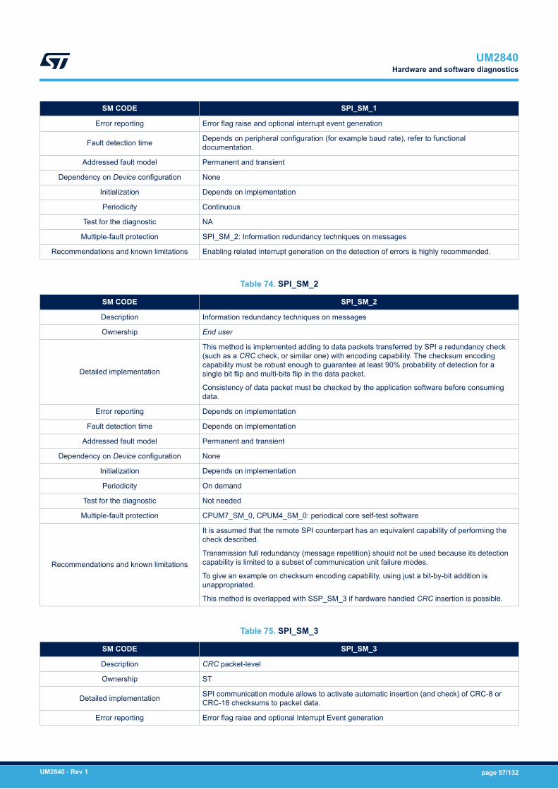
SM CODE SPI_SM_1
Error reporting Error flag raise and optional interrupt event generation
Fault detection time Depends on peripheral configuration (for example baud rate), refer to functionaldocumentation.
Addressed fault model Permanent and transient
Dependency on Device configuration None
Initialization Depends on implementation
Periodicity Continuous
Test for the diagnostic NA
Multiple-fault protection SPI_SM_2: Information redundancy techniques on messages
Recommendations and known limitations Enabling related interrupt generation on the detection of errors is highly recommended.
Table 74. SPI_SM_2
SM CODE SPI_SM_2
Description Information redundancy techniques on messages
Ownership End user
Detailed implementation
This method is implemented adding to data packets transferred by SPI a redundancy check(such as a CRC check, or similar one) with encoding capability. The checksum encodingcapability must be robust enough to guarantee at least 90% probability of detection for asingle bit flip and multi-bits flip in the data packet.
Consistency of data packet must be checked by the application software before consumingdata.
Error reporting Depends on implementation
Fault detection time Depends on implementation
Addressed fault model Permanent and transient
Dependency on Device configuration None
Initialization Depends on implementation
Periodicity On demand
Test for the diagnostic Not needed
Multiple-fault protection CPUM7_SM_0, CPUM4_SM_0: periodical core self-test software
Recommendations and known limitations
It is assumed that the remote SPI counterpart has an equivalent capability of performing thecheck described.
Transmission full redundancy (message repetition) should not be used because its detectioncapability is limited to a subset of communication unit failure modes.
To give an example on checksum encoding capability, using just a bit-by-bit addition isunappropriated.
This method is overlapped with SSP_SM_3 if hardware handled CRC insertion is possible.
Table 75. SPI_SM_3
SM CODE SPI_SM_3
Description CRC packet-level
Ownership ST
Detailed implementation SPI communication module allows to activate automatic insertion (and check) of CRC-8 orCRC-18 checksums to packet data.
Error reporting Error flag raise and optional Interrupt Event generation
UM2840Hardware and software diagnostics
UM2840 - Rev 1 page 57/132
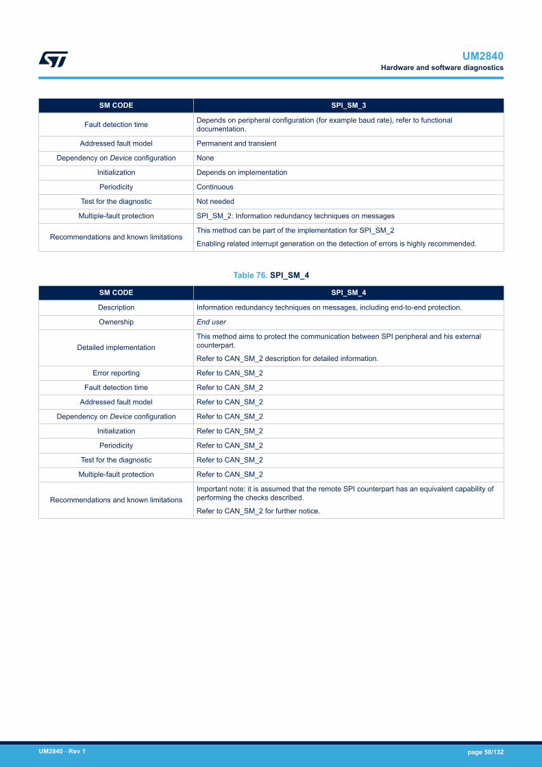
SM CODE SPI_SM_3
Fault detection time Depends on peripheral configuration (for example baud rate), refer to functionaldocumentation.
Addressed fault model Permanent and transient
Dependency on Device configuration None
Initialization Depends on implementation
Periodicity Continuous
Test for the diagnostic Not needed
Multiple-fault protection SPI_SM_2: Information redundancy techniques on messages
Recommendations and known limitationsThis method can be part of the implementation for SPI_SM_2
Enabling related interrupt generation on the detection of errors is highly recommended.
Table 76. SPI_SM_4
SM CODE SPI_SM_4
Description Information redundancy techniques on messages, including end-to-end protection.
Ownership End user
Detailed implementationThis method aims to protect the communication between SPI peripheral and his externalcounterpart.
Refer to CAN_SM_2 description for detailed information.
Error reporting Refer to CAN_SM_2
Fault detection time Refer to CAN_SM_2
Addressed fault model Refer to CAN_SM_2
Dependency on Device configuration Refer to CAN_SM_2
Initialization Refer to CAN_SM_2
Periodicity Refer to CAN_SM_2
Test for the diagnostic Refer to CAN_SM_2
Multiple-fault protection Refer to CAN_SM_2
Recommendations and known limitationsImportant note: it is assumed that the remote SPI counterpart has an equivalent capability ofperforming the checks described.
Refer to CAN_SM_2 for further notice.
UM2840Hardware and software diagnostics
UM2840 - Rev 1 page 58/132

3.6.16 USB on-the-go high-speed (OTG_HS)
Table 77. USB_SM_0
SM CODE USB_SM_0
Description Periodical read-back of configuration registers
Ownership End user
Detailed implementationThis method must be applied to USB configuration registers.
Detailed information on the implementation of this method can be found in Section 3.6.7 EXTIcontroller.
Error reporting Refer to NVIC_SM_0
Fault detection time Refer to NVIC_SM_0
Addressed fault model Refer to NVIC_SM_0
Dependency on Device configuration Refer to NVIC_SM_0
Initialization Refer to NVIC_SM_0
Periodicity Refer to NVIC_SM_0
Test for the diagnostic Refer to NVIC_SM_0
Multiple faults protection Refer to NVIC_SM_0
Recommendations and known limitations Refer to NVIC_SM_0
Table 78. USB_SM_1
SM CODE USB_SM_1
Description Protocol error signals
Ownership ST
Detailed implementationUSB communication module embeds protocol error checks (like overrun, underrun, NRZI, bitstuffing etc.) conceived to detect network-related abnormal conditions. These mechanisms are ableanyway to detect a marginal percentage of hardware random failures affecting the module itself
Error reporting Error flag raise and optional Interrupt Event generation
Fault detection time Depends on peripheral configuration (for example baud rate), refer to functional documentation
Addressed fault model Permanent and Transient
Dependency on Device configuration None
Initialization Depends on implementation
Periodicity Continuous
Test for the diagnostic Not needed
Multiple faults protection USB_SM_2: Information redundancy techniques on messages
Recommendations and known limitations Enabling related interrupt generation on the detection of errors is highly recommended.
UM2840Hardware and software diagnostics
UM2840 - Rev 1 page 59/132

Table 79. USB_SM_2
SM CODE USB_SM_2
Description Information redundancy techniques on messages
Ownership ST or End user
Detailed implementationThe implementation of required information redundancy on messages, USB communication moduleis fitted by hardware capability. It basically allows to activate the automatic insertion (and check) ofCRC checksums to packet data.
Error reporting Error flag raise and optional Interrupt Event generation
Fault detection time Depends on peripheral configuration (for example baud rate), refer to functional documentation
Addressed fault model Permanent and Transient
Dependency on Device configuration None
Initialization Error reporting configuration, if interrupt events are planned
Periodicity Continuous
Test for the diagnostic Not needed
Multiple faults protection USB_SM_2: Information redundancy techniques on messages
Recommendations and known limitations None
Table 80. USB_SM_3
SM CODE USB_SM_3
Description Information redundancy techniques on messages, including end-to-end protection.
Ownership End user
Detailed implementationThis method aims to protect the communication between an USB peripheral and his externalcounterpart.
Refer to CAN_SM_2 description for detailed information
Error reporting Refer to CAN_SM_2
Fault detection time Refer to CAN_SM_2
Addressed fault model Refer to CAN_SM_2
Dependency on Device configuration Refer to CAN_SM_2
Initialization Refer to CAN_SM_2
Periodicity Refer to CAN_SM_2
Test for the diagnostic Refer to CAN_SM_2
Multiple faults protection Refer to CAN_SM_2
Recommendations and known limitationsThis method apply in case USB bulk or isochronous transfers are used. For other transfers modesthe USB hardware protocol already implements several features of this requirement.
Refer to CAN_SM_2 for further notice
UM2840Hardware and software diagnostics
UM2840 - Rev 1 page 60/132
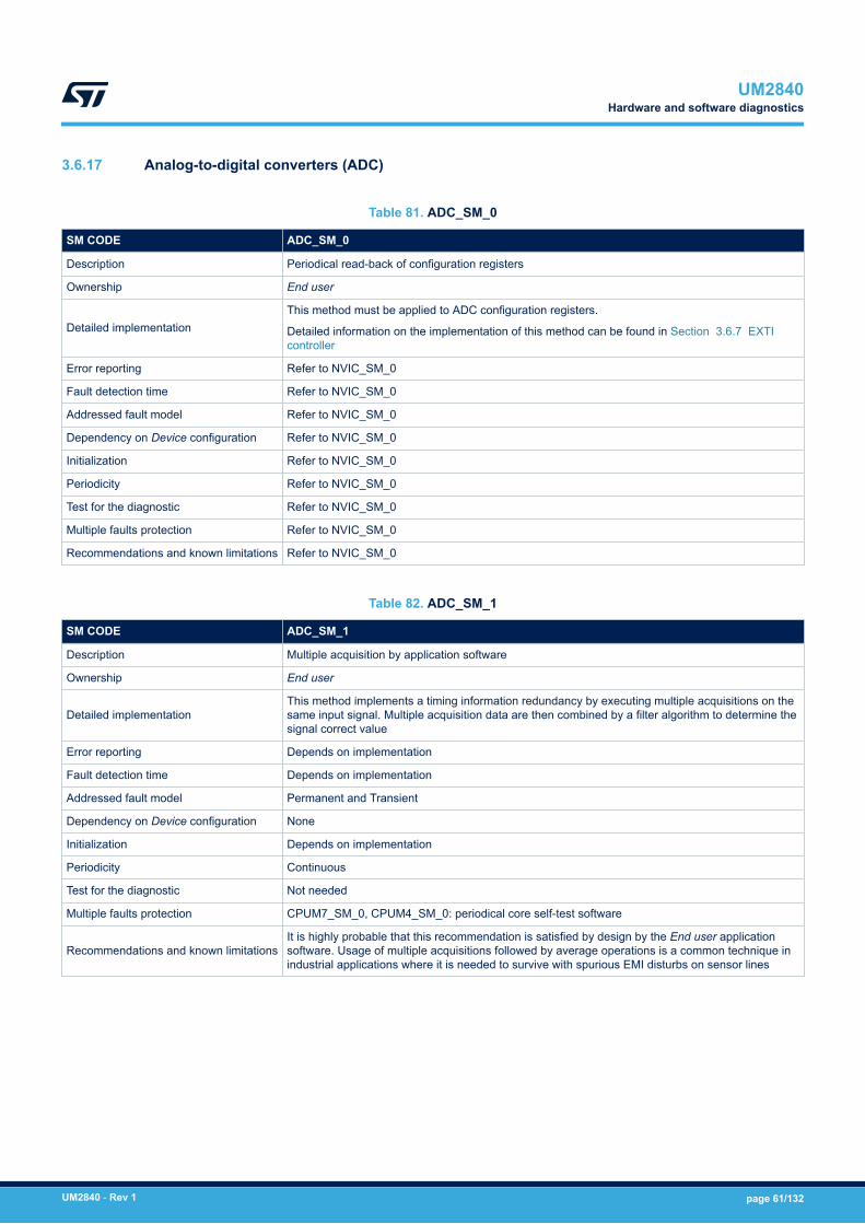
3.6.17 Analog-to-digital converters (ADC)
Table 81. ADC_SM_0
SM CODE ADC_SM_0
Description Periodical read-back of configuration registers
Ownership End user
Detailed implementationThis method must be applied to ADC configuration registers.
Detailed information on the implementation of this method can be found in Section 3.6.7 EXTIcontroller
Error reporting Refer to NVIC_SM_0
Fault detection time Refer to NVIC_SM_0
Addressed fault model Refer to NVIC_SM_0
Dependency on Device configuration Refer to NVIC_SM_0
Initialization Refer to NVIC_SM_0
Periodicity Refer to NVIC_SM_0
Test for the diagnostic Refer to NVIC_SM_0
Multiple faults protection Refer to NVIC_SM_0
Recommendations and known limitations Refer to NVIC_SM_0
Table 82. ADC_SM_1
SM CODE ADC_SM_1
Description Multiple acquisition by application software
Ownership End user
Detailed implementationThis method implements a timing information redundancy by executing multiple acquisitions on thesame input signal. Multiple acquisition data are then combined by a filter algorithm to determine thesignal correct value
Error reporting Depends on implementation
Fault detection time Depends on implementation
Addressed fault model Permanent and Transient
Dependency on Device configuration None
Initialization Depends on implementation
Periodicity Continuous
Test for the diagnostic Not needed
Multiple faults protection CPUM7_SM_0, CPUM4_SM_0: periodical core self-test software
Recommendations and known limitationsIt is highly probable that this recommendation is satisfied by design by the End user applicationsoftware. Usage of multiple acquisitions followed by average operations is a common technique inindustrial applications where it is needed to survive with spurious EMI disturbs on sensor lines
UM2840Hardware and software diagnostics
UM2840 - Rev 1 page 61/132
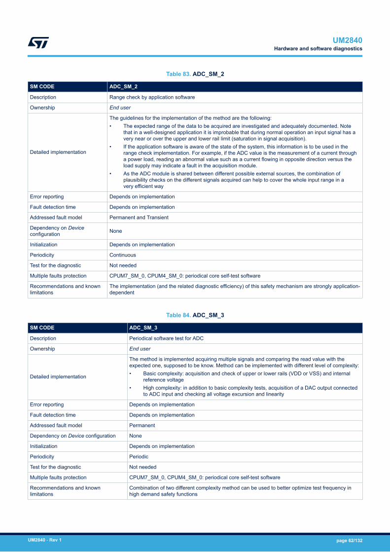
Table 83. ADC_SM_2
SM CODE ADC_SM_2
Description Range check by application software
Ownership End user
Detailed implementation
The guidelines for the implementation of the method are the following:• The expected range of the data to be acquired are investigated and adequately documented. Note
that in a well-designed application it is improbable that during normal operation an input signal has avery near or over the upper and lower rail limit (saturation in signal acquisition).
• If the application software is aware of the state of the system, this information is to be used in therange check implementation. For example, if the ADC value is the measurement of a current througha power load, reading an abnormal value such as a current flowing in opposite direction versus theload supply may indicate a fault in the acquisition module.
• As the ADC module is shared between different possible external sources, the combination ofplausibility checks on the different signals acquired can help to cover the whole input range in avery efficient way
Error reporting Depends on implementation
Fault detection time Depends on implementation
Addressed fault model Permanent and Transient
Dependency on Deviceconfiguration None
Initialization Depends on implementation
Periodicity Continuous
Test for the diagnostic Not needed
Multiple faults protection CPUM7_SM_0, CPUM4_SM_0: periodical core self-test software
Recommendations and knownlimitations
The implementation (and the related diagnostic efficiency) of this safety mechanism are strongly application-dependent
Table 84. ADC_SM_3
SM CODE ADC_SM_3
Description Periodical software test for ADC
Ownership End user
Detailed implementation
The method is implemented acquiring multiple signals and comparing the read value with theexpected one, supposed to be know. Method can be implemented with different level of complexity:• Basic complexity: acquisition and check of upper or lower rails (VDD or VSS) and internal
reference voltage• High complexity: in addition to basic complexity tests, acquisition of a DAC output connected
to ADC input and checking all voltage excursion and linearity
Error reporting Depends on implementation
Fault detection time Depends on implementation
Addressed fault model Permanent
Dependency on Device configuration None
Initialization Depends on implementation
Periodicity Periodic
Test for the diagnostic Not needed
Multiple faults protection CPUM7_SM_0, CPUM4_SM_0: periodical core self-test software
Recommendations and knownlimitations
Combination of two different complexity method can be used to better optimize test frequency inhigh demand safety functions
UM2840Hardware and software diagnostics
UM2840 - Rev 1 page 62/132

Table 85. ADC_SM_4
SM CODE ADC_SM_4
Description 1oo2 scheme for ADC inputs
Ownership End user
Detailed implementationThis safety mechanism is implemented using two different SAR ADC channels belonging toseparate ADC modules to acquire the same input signal. The application software checks thecoherence between the two readings.
Error reporting Depends on implementation
Fault detection time Depends on implementation
Addressed fault model Permanent and Transient
Dependency on Device configuration None
Initialization Depends on implementation
Periodicity On demand
Test for the diagnostic Not needed
Multiple faults protection ADC_SM_0: Periodical read-back of ADC configuration registers
Recommendations and known limitations This method can be used in conjunction with ADC_SM_0/ ADC_SM_2/ ADC_SM_3 to achievehighest level of ADC module diagnostic coverage
UM2840Hardware and software diagnostics
UM2840 - Rev 1 page 63/132
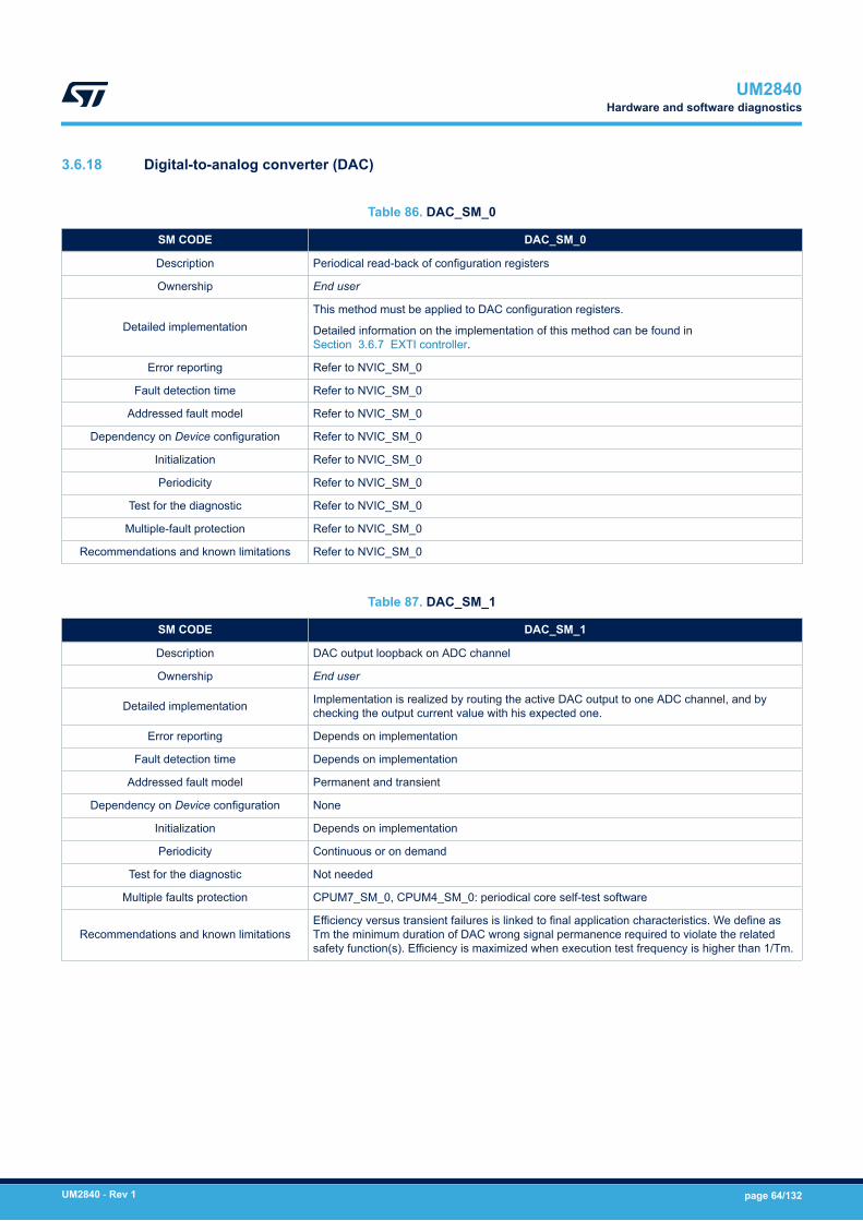
3.6.18 Digital-to-analog converter (DAC)
Table 86. DAC_SM_0
SM CODE DAC_SM_0
Description Periodical read-back of configuration registers
Ownership End user
Detailed implementationThis method must be applied to DAC configuration registers.
Detailed information on the implementation of this method can be found inSection 3.6.7 EXTI controller.
Error reporting Refer to NVIC_SM_0
Fault detection time Refer to NVIC_SM_0
Addressed fault model Refer to NVIC_SM_0
Dependency on Device configuration Refer to NVIC_SM_0
Initialization Refer to NVIC_SM_0
Periodicity Refer to NVIC_SM_0
Test for the diagnostic Refer to NVIC_SM_0
Multiple-fault protection Refer to NVIC_SM_0
Recommendations and known limitations Refer to NVIC_SM_0
Table 87. DAC_SM_1
SM CODE DAC_SM_1
Description DAC output loopback on ADC channel
Ownership End user
Detailed implementation Implementation is realized by routing the active DAC output to one ADC channel, and bychecking the output current value with his expected one.
Error reporting Depends on implementation
Fault detection time Depends on implementation
Addressed fault model Permanent and transient
Dependency on Device configuration None
Initialization Depends on implementation
Periodicity Continuous or on demand
Test for the diagnostic Not needed
Multiple faults protection CPUM7_SM_0, CPUM4_SM_0: periodical core self-test software
Recommendations and known limitationsEfficiency versus transient failures is linked to final application characteristics. We define asTm the minimum duration of DAC wrong signal permanence required to violate the relatedsafety function(s). Efficiency is maximized when execution test frequency is higher than 1/Tm.
UM2840Hardware and software diagnostics
UM2840 - Rev 1 page 64/132
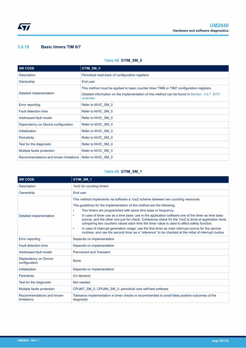
3.6.19 Basic timers TIM 6/7
Table 88. GTIM_SM_0
SM CODE GTIM_SM_0
Description Periodical read-back of configuration registers
Ownership End user
Detailed implementationThis method must be applied to basic counter timer TIM6 or TIM7 configuration registers.
Detailed information on the implementation of this method can be found in Section 3.6.7 EXTIcontroller
Error reporting Refer to NVIC_SM_0
Fault detection time Refer to NVIC_SM_0
Addressed fault model Refer to NVIC_SM_0
Dependency on Device configuration Refer to NVIC_SM_0
Initialization Refer to NVIC_SM_0
Periodicity Refer to NVIC_SM_0
Test for the diagnostic Refer to NVIC_SM_0
Multiple faults protection Refer to NVIC_SM_0
Recommendations and known limitations Refer to NVIC_SM_0
Table 89. GTIM_SM_1
SM CODE GTIM_SM_1
Description 1oo2 for counting timers
Ownership End user
Detailed implementation
This method implements via software a 1oo2 scheme between two counting resources.
The guidelines for the implementation of the method are the following:• Two timers are programmed with same time base or frequency.• In case of timer use as a time base: use in the application software one of the timer as time base
source, and the other one just for check. Coherence check for the 1oo2 is done at application level,comparing two counters values each time the timer value is used to affect safety function.
• In case of interrupt generation usage: use the first timer as main interrupt source for the serviceroutines, and use the second timer as a “reference” to be checked at the initial of interrupt routine
Error reporting Depends on implementation
Fault detection time Depends on implementation
Addressed fault model Permanent and Transient
Dependency on Deviceconfiguration None
Initialization Depends on implementation
Periodicity On demand
Test for the diagnostic Not needed
Multiple faults protection CPUM7_SM_0, CPUM4_SM_0: periodical core self-test software
Recommendations and knownlimitations
Tolerance implementation in timer checks is recommended to avoid false positive outcomes of thediagnostic
UM2840Hardware and software diagnostics
UM2840 - Rev 1 page 65/132
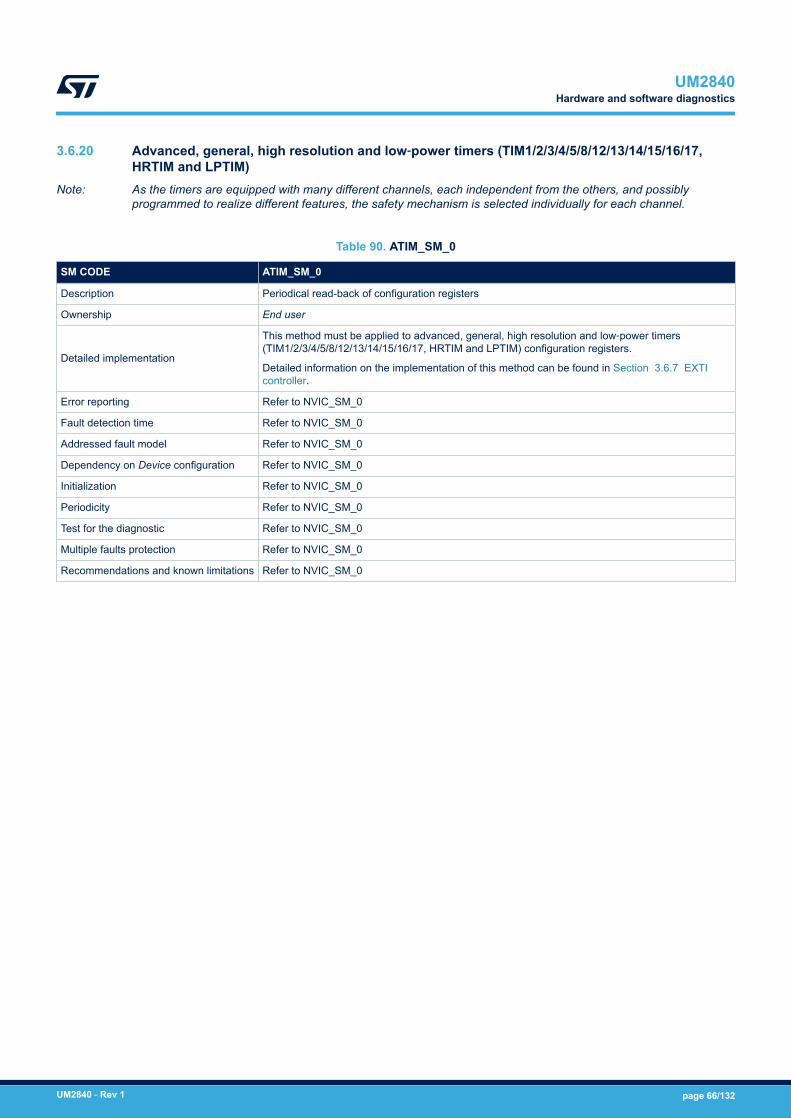
3.6.20 Advanced, general, high resolution and low‑power timers (TIM1/2/3/4/5/8/12/13/14/15/16/17,HRTIM and LPTIM)
Note: As the timers are equipped with many different channels, each independent from the others, and possiblyprogrammed to realize different features, the safety mechanism is selected individually for each channel.
Table 90. ATIM_SM_0
SM CODE ATIM_SM_0
Description Periodical read-back of configuration registers
Ownership End user
Detailed implementation
This method must be applied to advanced, general, high resolution and low‑power timers(TIM1/2/3/4/5/8/12/13/14/15/16/17, HRTIM and LPTIM) configuration registers.
Detailed information on the implementation of this method can be found in Section 3.6.7 EXTIcontroller.
Error reporting Refer to NVIC_SM_0
Fault detection time Refer to NVIC_SM_0
Addressed fault model Refer to NVIC_SM_0
Dependency on Device configuration Refer to NVIC_SM_0
Initialization Refer to NVIC_SM_0
Periodicity Refer to NVIC_SM_0
Test for the diagnostic Refer to NVIC_SM_0
Multiple faults protection Refer to NVIC_SM_0
Recommendations and known limitations Refer to NVIC_SM_0
UM2840Hardware and software diagnostics
UM2840 - Rev 1 page 66/132

Table 91. ATIM_SM_1
SM CODE ATIM_SM_1
Description 1oo2 for counting timers
Ownership End user
Detailed implementation
This method implements via software a 1oo2 scheme between two counting resources.
The guidelines for the implementation of the method are the following:• Two timers are programmed with same time base or frequency.• In case of timer use as a time base: use in the application software one of the timer as time base
source, and the other one just for check. Coherence check for the 1oo2 is done at application level,comparing two counters values each time the timer value is used to affect safety function.
• In case of interrupt generation usage: use the first timer as main interrupt source for the serviceroutines, and use the second timer as a “reference” to be checked at the initial of interrupt routine
Error reporting Depends on implementation
Fault detection time Depends on implementation
Addressed fault model Permanent and Transient
Dependency on Deviceconfiguration None
Initialization Depends on implementation
Periodicity On demand
Test for the diagnostic Not needed
Multiple faults protection CPUM7_SM_0, CPUM4_SM_0: periodical core self-test software
Recommendations and knownlimitations
Tolerance implementation in timer checks is recommended to avoid false positive outcomes of thediagnostic.
This method apply to timer channels merely used as elapsed time counters
Table 92. ATIM_SM_2
SM CODE ATIM_SM_2
Description 1oo2 for input capture timers
Ownership End user
Detailed implementation
This method is conceived to protect timers used for external signal acquisition and measurement,like “input capture” and “encoder reading”. Implementation requires to connect the external signalsalso to a redundant timer, and to perform a coherence check on the measured data at applicationlevel.
Coherence check between timers is executed each time the reading is used by the applicationsoftware
Error reporting Depends on implementation
Fault detection time Depends on implementation
Addressed fault model Permanent and Transient
Dependency on Device configuration None
Initialization Depends on implementation
Periodicity On demand
Test for the diagnostic Not needed
Multiple faults protection CPUM7_SM_0, CPUM4_SM_0: periodical core self-test software
Recommendations and knownlimitations
To reduce the potential effect of common cause failures, it is suggested to use for redundant checka channel belonging to a different timer module and mapped to non-adjacent pin on the devicepackage
UM2840Hardware and software diagnostics
UM2840 - Rev 1 page 67/132

Table 93. ATIM_SM_3
SM CODE ATIM_SM_3
Description Loop-back scheme for PWM outputs
Ownership End user
Detailed implementation
This method is implemented by connecting the PWM to a separate timer channel to acquire the generatedwaveform characteristics.
The guidelines are the following:• Both PWM frequency and duty cycle are measured and checked versus the expected value.• To reduce the potential effect of common cause failure, it is suggested to use for the loopback check a
channel belonging to a different timer module and mapped to non-adjacent pins on the device package.
This measure can be replaced under the End user responsibility by different loopback schemes already inplace in the final application and rated as equivalent. For example if the PWM is used to drive an externalpower load, the reading of the on-line current value can be used instead of the PWM duty cycle measurement.
Error reporting Depends on implementation
Fault detection time Depends on implementation
Addressed fault model Permanent and Transient
Dependency on Deviceconfiguration None
Initialization Depends on implementation
Periodicity Continuous
Test for the diagnostic Not needed
Multiple faults protection CPUM7_SM_0, CPUM4_SM_0: periodical core self-test software
Recommendations andknown limitations
Efficiency versus transient failures is linked to final application characteristics. We define as Tm the minimumduration of PWM wrong signal permanence (wrong frequency, wrong duty, or both) required to violate therelated safety function(s). Efficiency is maximized when execution test frequency is higher than 1/Tm
Table 94. ATIM_SM_4
SM CODE ATIM_SM_4
Description Lock bit protection for timers
Ownership ST
Detailed implementationThis safety mechanism allows the End user to lock down specified configuration options, avoidingunintended modifications by application software. It addresses therefore software developmentsystematic faults
Error reporting NA
Fault detection time NA
Addressed fault model None (Fault avoidance)
Dependency on Device configuration None
Initialization Lock protection must be enabled using LOCK bits in the TIMx_BDTR register
Periodicity Continuous
Test for the diagnostic NA
Multiple faults protection NA
Recommendations and known limitations This method does not addresses timer configuration changes due to soft-errors
Note: IRTIM is not individually mentioned here, being mainly implemented by TIM16 and TIM17 functions. Refertherefore to related prescriptions.
UM2840Hardware and software diagnostics
UM2840 - Rev 1 page 68/132

3.6.21 General-purpose input/output (GPIO) - Port A/B/C/D/E/F/G/H/I/J/K
Table 95. GPIO_SM_0
SM CODE GPIO_SM_0
Description Periodical read-back of configuration registers
Ownership End user
Detailed implementationThis method must be applied to GPIO configuration registers.
Detailed information on the implementation of this method can be found inSection 3.6.7 EXTI controller.
Error reporting Refer to NVIC_SM_0
Fault detection time Refer to NVIC_SM_0
Addressed fault model Refer to NVIC_SM_0
Dependency on Device configuration GPIO availability can differ according to part number
Initialization Refer to NVIC_SM_0
Periodicity Refer to NVIC_SM_0
Test for the diagnostic Refer to NVIC_SM_0
Multiple-fault protection Refer to NVIC_SM_0
Recommendations and known limitations Refer to NVIC_SM_0
Table 96. GPIO_SM_1
SM CODE GPIO_SM_1
Description 1oo2 for input GPIO lines
Ownership End user
Detailed implementation
This method addresses GPIO lines used as inputs. Implementation is done by connectingthe external safety-related signal to two independent GPIO lines. Comparison between thetwo GPIO values is executed by application software each time the signal is used to affectapplication software behavior.
Error reporting Depends on implementation
Fault detection time Depends on implementation
Addressed fault model Permanent and transient
Dependency on Device configuration None
Initialization Depends on implementation
Periodicity On demand
Test for the diagnostic Not needed
Multiple-fault protection CPUM7_SM_0, CPUM4_SM_0: periodical core self-test software
Recommendations and known limitations
To reduce the potential impact of common cause failure, it is recommended to use GPIO lines:• belonging to different I/O ports (for instance port A and B)• with different bit port number (for instance PA1 and PB5)• mapped to non-adjacent pins on the device package
Table 97. GPIO_SM_2
SM CODE GPIO_SM_2
Description Loopback scheme for output GPIO lines
UM2840Hardware and software diagnostics
UM2840 - Rev 1 page 69/132
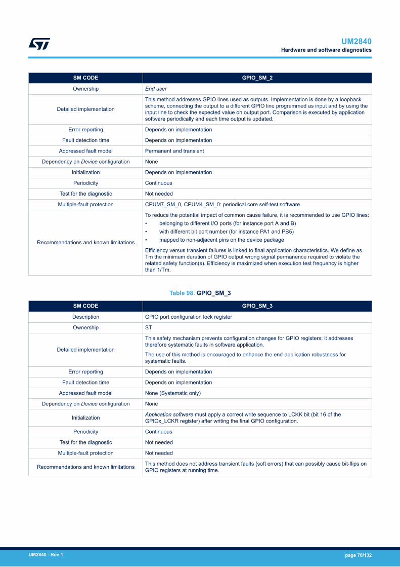
SM CODE GPIO_SM_2
Ownership End user
Detailed implementation
This method addresses GPIO lines used as outputs. Implementation is done by a loopbackscheme, connecting the output to a different GPIO line programmed as input and by using theinput line to check the expected value on output port. Comparison is executed by applicationsoftware periodically and each time output is updated.
Error reporting Depends on implementation
Fault detection time Depends on implementation
Addressed fault model Permanent and transient
Dependency on Device configuration None
Initialization Depends on implementation
Periodicity Continuous
Test for the diagnostic Not needed
Multiple-fault protection CPUM7_SM_0, CPUM4_SM_0: periodical core self-test software
Recommendations and known limitations
To reduce the potential impact of common cause failure, it is recommended to use GPIO lines:• belonging to different I/O ports (for instance port A and B)• with different bit port number (for instance PA1 and PB5)• mapped to non-adjacent pins on the device package
Efficiency versus transient failures is linked to final application characteristics. We define asTm the minimum duration of GPIO output wrong signal permanence required to violate therelated safety function(s). Efficiency is maximized when execution test frequency is higherthan 1/Tm.
Table 98. GPIO_SM_3
SM CODE GPIO_SM_3
Description GPIO port configuration lock register
Ownership ST
Detailed implementation
This safety mechanism prevents configuration changes for GPIO registers; it addressestherefore systematic faults in software application.
The use of this method is encouraged to enhance the end-application robustness forsystematic faults.
Error reporting Depends on implementation
Fault detection time Depends on implementation
Addressed fault model None (Systematic only)
Dependency on Device configuration None
Initialization Application software must apply a correct write sequence to LCKK bit (bit 16 of theGPIOx_LCKR register) after writing the final GPIO configuration.
Periodicity Continuous
Test for the diagnostic Not needed
Multiple-fault protection Not needed
Recommendations and known limitations This method does not address transient faults (soft errors) that can possibly cause bit-flips onGPIO registers at running time.
UM2840Hardware and software diagnostics
UM2840 - Rev 1 page 70/132
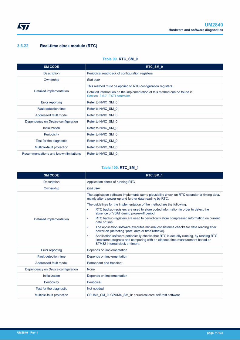
3.6.22 Real-time clock module (RTC)
Table 99. RTC_SM_0
SM CODE RTC_SM_0
Description Periodical read-back of configuration registers
Ownership End user
Detailed implementationThis method must be applied to RTC configuration registers.
Detailed information on the implementation of this method can be found inSection 3.6.7 EXTI controller.
Error reporting Refer to NVIC_SM_0
Fault detection time Refer to NVIC_SM_0
Addressed fault model Refer to NVIC_SM_0
Dependency on Device configuration Refer to NVIC_SM_0
Initialization Refer to NVIC_SM_0
Periodicity Refer to NVIC_SM_0
Test for the diagnostic Refer to NVIC_SM_0
Multiple-fault protection Refer to NVIC_SM_0
Recommendations and known limitations Refer to NVIC_SM_0
Table 100. RTC_SM_1
SM CODE RTC_SM_1
Description Application check of running RTC
Ownership End user
Detailed implementation
The application software implements some plausibility check on RTC calendar or timing data,mainly after a power-up and further date reading by RTC.
The guidelines for the implementation of the method are the following:• RTC backup registers are used to store coded information in order to detect the
absence of VBAT during power-off period.• RTC backup registers are used to periodically store compressed information on current
date or time• The application software executes minimal consistence checks for date reading after
power-on (detecting “past” date or time retrieve).• Application software periodically checks that RTC is actually running, by reading RTC
timestamp progress and comparing with an elapsed time measurement based onSTM32 internal clock or timers.
Error reporting Depends on implementation
Fault detection time Depends on implementation
Addressed fault model Permanent and transient
Dependency on Device configuration None
Initialization Depends on implementation
Periodicity Periodical
Test for the diagnostic Not needed
Multiple-fault protection CPUM7_SM_0, CPUM4_SM_0: periodical core self-test software
UM2840Hardware and software diagnostics
UM2840 - Rev 1 page 71/132
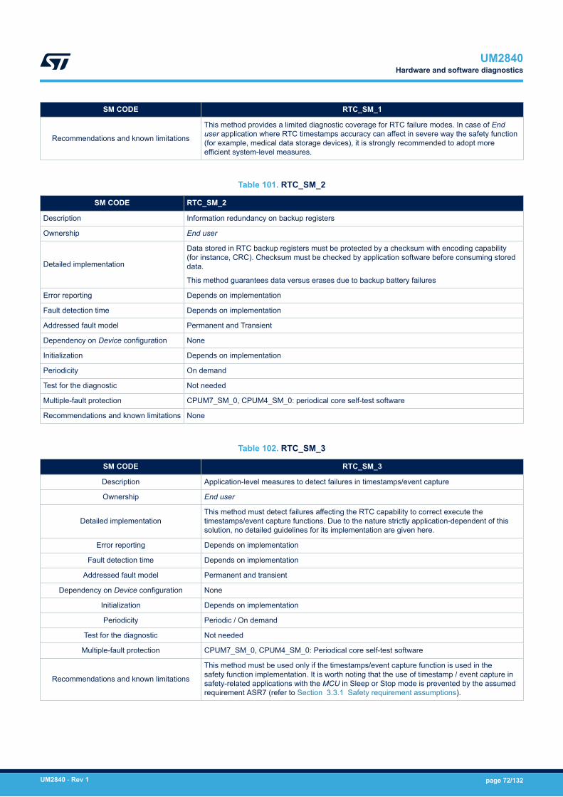
SM CODE RTC_SM_1
Recommendations and known limitations
This method provides a limited diagnostic coverage for RTC failure modes. In case of Enduser application where RTC timestamps accuracy can affect in severe way the safety function(for example, medical data storage devices), it is strongly recommended to adopt moreefficient system-level measures.
Table 101. RTC_SM_2
SM CODE RTC_SM_2
Description Information redundancy on backup registers
Ownership End user
Detailed implementation
Data stored in RTC backup registers must be protected by a checksum with encoding capability(for instance, CRC). Checksum must be checked by application software before consuming storeddata.
This method guarantees data versus erases due to backup battery failures
Error reporting Depends on implementation
Fault detection time Depends on implementation
Addressed fault model Permanent and Transient
Dependency on Device configuration None
Initialization Depends on implementation
Periodicity On demand
Test for the diagnostic Not needed
Multiple-fault protection CPUM7_SM_0, CPUM4_SM_0: periodical core self-test software
Recommendations and known limitations None
Table 102. RTC_SM_3
SM CODE RTC_SM_3
Description Application-level measures to detect failures in timestamps/event capture
Ownership End user
Detailed implementationThis method must detect failures affecting the RTC capability to correct execute thetimestamps/event capture functions. Due to the nature strictly application-dependent of thissolution, no detailed guidelines for its implementation are given here.
Error reporting Depends on implementation
Fault detection time Depends on implementation
Addressed fault model Permanent and transient
Dependency on Device configuration None
Initialization Depends on implementation
Periodicity Periodic / On demand
Test for the diagnostic Not needed
Multiple-fault protection CPUM7_SM_0, CPUM4_SM_0: Periodical core self-test software
Recommendations and known limitations
This method must be used only if the timestamps/event capture function is used in thesafety function implementation. It is worth noting that the use of timestamp / event capture insafety-related applications with the MCU in Sleep or Stop mode is prevented by the assumedrequirement ASR7 (refer to Section 3.3.1 Safety requirement assumptions).
UM2840Hardware and software diagnostics
UM2840 - Rev 1 page 72/132

3.6.23 Power controller (PWR)
Table 103. VSUP_SM_0
SM CODE VSUP_SM_0
Description Periodical read-back of configuration registers
Ownership End user
Detailed implementationThis method must be applied to configuration registers.
Detailed information on the implementation of this method can be found in Section 3.6.7 EXTIcontroller.
Error reporting Refer to NVIC_SM_0
Fault detection time Refer to NVIC_SM_0
Addressed fault model Refer to NVIC_SM_0
Dependency on Device configuration Refer to NVIC_SM_0
Initialization Refer to NVIC_SM_0
Periodicity Refer to NVIC_SM_0
Test for the diagnostic Refer to NVIC_SM_0
Multiple faults protection Refer to NVIC_SM_0
Recommendations and known limitations Refer to NVIC_SM_0
Table 104. VSUP_SM_1
SM CODE VSUP_SM_1
Description Supply voltage internal monitoring (PVD)
Ownership ST
Detailed implementationThe device features an embedded programmable voltage detector (PVD) that monitors the VDDpower supply and compares it to the VPVD threshold. An interrupt can be generated when VDDdrops below the VPVD threshold or when VDD is higher than the VPVD threshold
Error reporting Interrupt Event generation
Fault detection time Depends on threshold programming, refer to functional documentation
Addressed fault model Permanent and Transient
Dependency on Device configuration None
Initialization Protection enable by PVDE bit and threshold programming in Power control register (PWR_CR)
Periodicity Continuous
Test for the diagnostic Not needed
Multiple faults protection DIAG_SM_0: Periodical read-back of hardware diagnostics configuration registers
Recommendations and knownlimitations
Internal monitoring PVD has limited capability to address failures affecting STM32H7 dual-coreinternal voltage regulator. Refer to device FMEA for details
Enabling related interrupt generation on the detection of errors is highly recommended.
UM2840Hardware and software diagnostics
UM2840 - Rev 1 page 73/132

Table 105. VSUP_SM_2
SM CODE VSUP_SM_2
Description External watchdog
Ownership End user
Detailed implementation
Failures in the power supplies for digital logic (core or peripherals) may lead to alteration ofthe application software timing, which can be detected by the external watchdog as safetymechanism introduced to monitor the application software control flow. Refer to CPU_SM_5 forfurther information.
Error reporting Refer to CPU_SM_5
Fault detection time Refer to CPU_SM_5
Addressed fault model Refer to CPU_SM_5
Dependency on Device configuration Refer to CPU_SM_5
Initialization Refer to CPU_SM_5
Periodicity Refer to CPU_SM_5
Test for the diagnostic Refer to CPU_SM_5
Multiple faults protection Refer to CPU_SM_5
Recommendations and known limitations Refer to CPU_SM_5
Table 106. VSUP_SM_3
SM CODE VSUP_SM_3
Description Internal temperature sensor check
Ownership End user
Detailed implementationThe internal temperature sensor must be periodically tested in order to detect abnormal increaseof the die temperature – hardware faults in supply voltage system may cause excessive powerconsumption and consequent temperature rise
Error reporting Depends on implementation
Fault detection time Depends on implementation
Addressed fault model Permanent
Dependency on Device configuration None
Initialization None
Periodicity Periodic
Test for the diagnostic Not needed
Multiple faults protection CPUM7_SM_0, CPUM4_SM_0: periodical core self-test software
Recommendations and known limitationsThis method also mitigates the eventuality of common-cause affecting the MCU and due to too hightemperature.
Refer to the device datasheet to set the threshold temperature
UM2840Hardware and software diagnostics
UM2840 - Rev 1 page 74/132
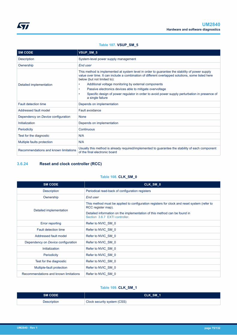
Table 107. VSUP_SM_5
SM CODE VSUP_SM_5
Description System-level power supply management
Ownership End user
Detailed implementation
This method is implemented at system level in order to guarantee the stability of power supplyvalue over time. It can include a combination of different overlapped solutions, some listed herebelow (but not limited to):• Additional voltage monitoring by external components• Passive electronics devices able to mitigate overvoltage• Specific design of power regulator in order to avoid power supply perturbation in presence of
a single failure
Fault detection time Depends on implementation
Addressed fault model Fault avoidance
Dependency on Device configuration None
Initialization Depends on implementation
Periodicity Continuous
Test for the diagnostic N/A
Multiple faults protection N/A
Recommendations and known limitations Usually this method is already required/implemented to guarantee the stability of each componentof the final electronic board
3.6.24 Reset and clock controller (RCC)
Table 108. CLK_SM_0
SM CODE CLK_SM_0
Description Periodical read-back of configuration registers
Ownership End user
Detailed implementation
This method must be applied to configuration registers for clock and reset system (refer toRCC register map).
Detailed information on the implementation of this method can be found inSection 3.6.7 EXTI controller.
Error reporting Refer to NVIC_SM_0
Fault detection time Refer to NVIC_SM_0
Addressed fault model Refer to NVIC_SM_0
Dependency on Device configuration Refer to NVIC_SM_0
Initialization Refer to NVIC_SM_0
Periodicity Refer to NVIC_SM_0
Test for the diagnostic Refer to NVIC_SM_0
Multiple-fault protection Refer to NVIC_SM_0
Recommendations and known limitations Refer to NVIC_SM_0
Table 109. CLK_SM_1
SM CODE CLK_SM_1
Description Clock security system (CSS)
UM2840Hardware and software diagnostics
UM2840 - Rev 1 page 75/132

SM CODE CLK_SM_1
Ownership ST
Detailed implementation
The clock security system (CSS) detects the loss of high-speed external (HSE) oscillator clockactivity and executes the corresponding recovery action, such as:• Switch-off HSE• Commutation on the HSI• Generation of related NMI
Error reporting NMI
Fault detection time Depends on implementation (clock frequency value).
Addressed fault model Permanent and transient
Dependency on Device configuration None
Initialization CSS protection must be enabled through Clock interrupt register (RCC_CIR) after bootstabilization.
Periodicity Continuous
Test for the diagnostic CLK_SM_0: periodical read-back of configuration registers
Multiple-fault protection CPU_SM_5: external watchdog
Recommendations and known limitations It is recommended to carefully read reference manual instruction on NMI generation, in orderto correctly managing the faulty situation by Application software.
Table 110. CLK_SM_2
SM CODE CLK_SM_2
Description External watchdog
Ownership ST
Detailed implementation The external watchdog is able to detect failures in internal main MCU clock (lower frequency).Refer to CPU_SM_5 for further details.
Error reporting Depends on implementation
Fault detection time Depends on implementation (watchdog timeout interval).
Addressed fault model Permanent
Dependency on Device configuration None
Initialization Depends on implementation
Periodicity Continuous
Test for the diagnostic Not needed
Multiple-fault protection CPUM7_SM_1, CPUM4_SM_1: control flow monitoring in application software
Recommendations and known limitations If a time window function option is used, End user must consider possible tolerance inapplication software execution, to avoid false error reports (affecting system availability).
Table 111. CLK_SM_3
SM CODE CLK_SM_3
Description Internal clock cross-measure
Ownership End user
Detailed implementation
This method is implemented using TIM14 capabilities to be fed by the 32 KHz RTC clock oran external clock source (if available). TIM14 counter progresses are compared with anothercounter (fed by internal clock). Abnormal values of oscillator frequency can therefore bedetected.
Error reporting Depends on implementation
UM2840Hardware and software diagnostics
UM2840 - Rev 1 page 76/132
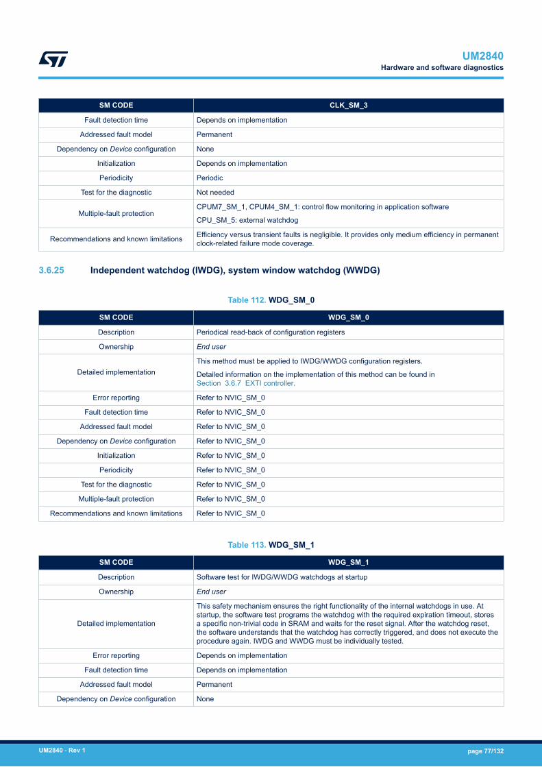
SM CODE CLK_SM_3
Fault detection time Depends on implementation
Addressed fault model Permanent
Dependency on Device configuration None
Initialization Depends on implementation
Periodicity Periodic
Test for the diagnostic Not needed
Multiple-fault protectionCPUM7_SM_1, CPUM4_SM_1: control flow monitoring in application software
CPU_SM_5: external watchdog
Recommendations and known limitations Efficiency versus transient faults is negligible. It provides only medium efficiency in permanentclock-related failure mode coverage.
3.6.25 Independent watchdog (IWDG), system window watchdog (WWDG)
Table 112. WDG_SM_0
SM CODE WDG_SM_0
Description Periodical read-back of configuration registers
Ownership End user
Detailed implementationThis method must be applied to IWDG/WWDG configuration registers.
Detailed information on the implementation of this method can be found inSection 3.6.7 EXTI controller.
Error reporting Refer to NVIC_SM_0
Fault detection time Refer to NVIC_SM_0
Addressed fault model Refer to NVIC_SM_0
Dependency on Device configuration Refer to NVIC_SM_0
Initialization Refer to NVIC_SM_0
Periodicity Refer to NVIC_SM_0
Test for the diagnostic Refer to NVIC_SM_0
Multiple-fault protection Refer to NVIC_SM_0
Recommendations and known limitations Refer to NVIC_SM_0
Table 113. WDG_SM_1
SM CODE WDG_SM_1
Description Software test for IWDG/WWDG watchdogs at startup
Ownership End user
Detailed implementation
This safety mechanism ensures the right functionality of the internal watchdogs in use. Atstartup, the software test programs the watchdog with the required expiration timeout, storesa specific non-trivial code in SRAM and waits for the reset signal. After the watchdog reset,the software understands that the watchdog has correctly triggered, and does not execute theprocedure again. IWDG and WWDG must be individually tested.
Error reporting Depends on implementation
Fault detection time Depends on implementation
Addressed fault model Permanent
Dependency on Device configuration None
UM2840Hardware and software diagnostics
UM2840 - Rev 1 page 77/132
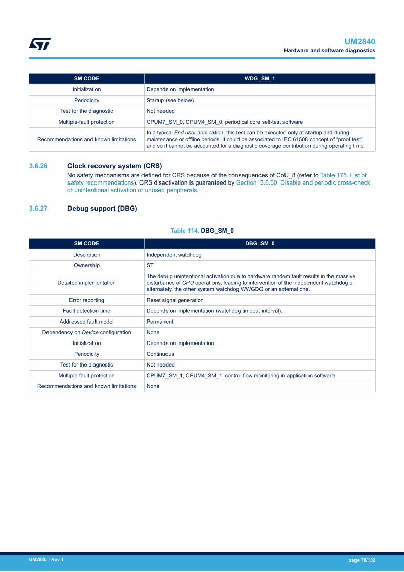
SM CODE WDG_SM_1
Initialization Depends on implementation
Periodicity Startup (see below)
Test for the diagnostic Not needed
Multiple-fault protection CPUM7_SM_0, CPUM4_SM_0: periodical core self-test software
Recommendations and known limitationsIn a typical End user application, this test can be executed only at startup and duringmaintenance or offline periods. It could be associated to IEC 61508 concept of “proof test”and so it cannot be accounted for a diagnostic coverage contribution during operating time.
3.6.26 Clock recovery system (CRS)No safety mechanisms are defined for CRS because of the consequences of CoU_8 (refer to Table 175. List ofsafety recommendations). CRS disactivation is guaranteed by Section 3.6.50 Disable and periodic cross-checkof unintentional activation of unused peripherals.
3.6.27 Debug support (DBG)
Table 114. DBG_SM_0
SM CODE DBG_SM_0
Description Independent watchdog
Ownership ST
Detailed implementationThe debug unintentional activation due to hardware random fault results in the massivedisturbance of CPU operations, leading to intervention of the independent watchdog oralternately, the other system watchdog WWGDG or an external one.
Error reporting Reset signal generation
Fault detection time Depends on implementation (watchdog timeout interval).
Addressed fault model Permanent
Dependency on Device configuration None
Initialization Depends on implementation
Periodicity Continuous
Test for the diagnostic Not needed
Multiple-fault protection CPUM7_SM_1, CPUM4_SM_1: control flow monitoring in application software
Recommendations and known limitations None
UM2840Hardware and software diagnostics
UM2840 - Rev 1 page 78/132

3.6.28 Cyclic redundancy-check module (CRC)
Table 115. CRC_SM_0
SM CODE CRC_SM_0
Description CRC self-coverage
Ownership ST
Detailed implementation
The CRC algorithm implemented in this module (CRC-32 Ethernet polynomial: 0x4C11DB7) offersexcellent features in terms of error detection in the message. Therefore permanent and transientfaults affecting CRC computations are easily detected by any operations using the module torecompute an expected signature
Error reporting Depends on implementation
Fault detection time Depends on implementation
Addressed fault model Permanent and Transient
Dependency on Device configuration None
Initialization Depends on implementation
Periodicity Continuous
Test for the diagnostic Not needed
Multiple faults protection CPUM7_SM_0, CPUM4_SM_0: periodical core self-test software
Recommendations and known limitations None
3.6.29 System configuration controller (SYSCFG)
Table 116. SYSCFG_SM_0
SM CODE SYSCFG_SM_0
Description Periodical read-back of configuration registers
Ownership End user
Detailed implementation
This method must be applied to System Configuration controller configuration registers.
This method is strongly recommended to protect registers related to hardware diagnosticsactivation and error reporting chain related features.
Detailed information on the implementation of this method can be found inSection 3.6.7 EXTI controller.
Error reporting Refer to NVIC_SM_0
Fault detection time Refer to NVIC_SM_0
Addressed fault model Refer to NVIC_SM_0
Dependency on Device configuration Refer to NVIC_SM_0
Initialization Refer to NVIC_SM_0
Periodicity Refer to NVIC_SM_0
Test for the diagnostic Refer to NVIC_SM_0
Multiple-fault protection Refer to NVIC_SM_0
Recommendations and known limitations This method is mainly overlapped by several other “configuration register read-backs”required for other MCU peripherals. It is reported here for the sake of completeness.
UM2840Hardware and software diagnostics
UM2840 - Rev 1 page 79/132
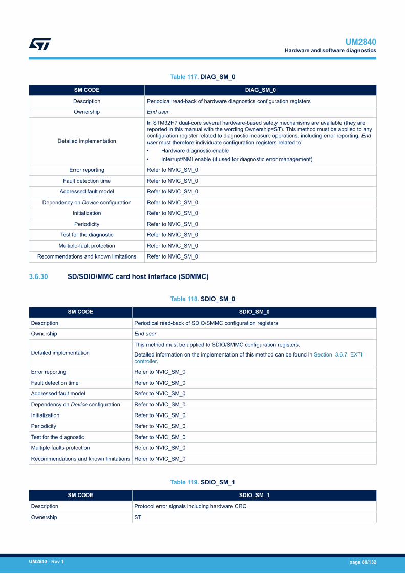
Table 117. DIAG_SM_0
SM CODE DIAG_SM_0
Description Periodical read-back of hardware diagnostics configuration registers
Ownership End user
Detailed implementation
In STM32H7 dual-core several hardware-based safety mechanisms are available (they arereported in this manual with the wording Ownership=ST). This method must be applied to anyconfiguration register related to diagnostic measure operations, including error reporting. Enduser must therefore individuate configuration registers related to:• Hardware diagnostic enable• Interrupt/NMI enable (if used for diagnostic error management)
Error reporting Refer to NVIC_SM_0
Fault detection time Refer to NVIC_SM_0
Addressed fault model Refer to NVIC_SM_0
Dependency on Device configuration Refer to NVIC_SM_0
Initialization Refer to NVIC_SM_0
Periodicity Refer to NVIC_SM_0
Test for the diagnostic Refer to NVIC_SM_0
Multiple-fault protection Refer to NVIC_SM_0
Recommendations and known limitations Refer to NVIC_SM_0
3.6.30 SD/SDIO/MMC card host interface (SDMMC)
Table 118. SDIO_SM_0
SM CODE SDIO_SM_0
Description Periodical read-back of SDIO/SMMC configuration registers
Ownership End user
Detailed implementationThis method must be applied to SDIO/SMMC configuration registers.
Detailed information on the implementation of this method can be found in Section 3.6.7 EXTIcontroller.
Error reporting Refer to NVIC_SM_0
Fault detection time Refer to NVIC_SM_0
Addressed fault model Refer to NVIC_SM_0
Dependency on Device configuration Refer to NVIC_SM_0
Initialization Refer to NVIC_SM_0
Periodicity Refer to NVIC_SM_0
Test for the diagnostic Refer to NVIC_SM_0
Multiple faults protection Refer to NVIC_SM_0
Recommendations and known limitations Refer to NVIC_SM_0
Table 119. SDIO_SM_1
SM CODE SDIO_SM_1
Description Protocol error signals including hardware CRC
Ownership ST
UM2840Hardware and software diagnostics
UM2840 - Rev 1 page 80/132
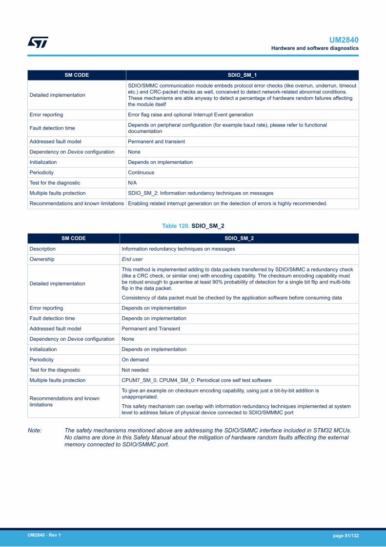
SM CODE SDIO_SM_1
Detailed implementation
SDIO/SMMC communication module embeds protocol error checks (like overrun, underrun, timeoutetc.) and CRC-packet checks as well, conceived to detect network-related abnormal conditions.These mechanisms are able anyway to detect a percentage of hardware random failures affectingthe module itself
Error reporting Error flag raise and optional Interrupt Event generation
Fault detection time Depends on peripheral configuration (for example baud rate), please refer to functionaldocumentation
Addressed fault model Permanent and transient
Dependency on Device configuration None
Initialization Depends on implementation
Periodicity Continuous
Test for the diagnostic N/A
Multiple faults protection SDIO_SM_2: Information redundancy techniques on messages
Recommendations and known limitations Enabling related interrupt generation on the detection of errors is highly recommended.
Table 120. SDIO_SM_2
SM CODE SDIO_SM_2
Description Information redundancy techniques on messages
Ownership End user
Detailed implementation
This method is implemented adding to data packets transferred by SDIO/SMMC a redundancy check(like a CRC check, or similar one) with encoding capability. The checksum encoding capability mustbe robust enough to guarantee at least 90% probability of detection for a single bit flip and multi-bitsflip in the data packet.
Consistency of data packet must be checked by the application software before consuming data
Error reporting Depends on implementation
Fault detection time Depends on implementation
Addressed fault model Permanent and Transient
Dependency on Device configuration None
Initialization Depends on implementation
Periodicity On demand
Test for the diagnostic Not needed
Multiple faults protection CPUM7_SM_0, CPUM4_SM_0: Periodical core self test software
Recommendations and knownlimitations
To give an example on checksum encoding capability, using just a bit-by-bit addition isunappropriated.
This safety mechanism can overlap with information redundancy techniques implemented at systemlevel to address failure of physical device connected to SDIO/SMMMC port
Note: The safety mechanisms mentioned above are addressing the SDIO/SMMC interface included in STM32 MCUs.No claims are done in this Safety Manual about the mitigation of hardware random faults affecting the externalmemory connected to SDIO/SMMC port.
UM2840Hardware and software diagnostics
UM2840 - Rev 1 page 81/132

3.6.31 Flexible static memory controller (FSMC)
Table 121. FSMC_SM_0
SM CODE FSMC_SM_0
Description Control flow monitoring in application software
Ownership End user
Detailed implementation
If FSMC is used to connect an external memory containing software code to be executed by theCPU, permanent and transient faults affecting the FSMC memory controller are able to interfere withthe access operation by the CPU, leading to wrong data or instruction fetches. A strong control flowmechanism linked to a system watchdog is able to detect such failures, in case they interfere with theexpected flow of the application software.
The implementation of this method is identical to the one reported for CPUM7_SM_1, CPUM4_SM_1,refer there for details
Error reporting Depends on implementation
Fault detection time Depends on implementation. Higher value is fixed by watchdog timeout interval
Addressed fault model Permanent and Transient
Dependency on Deviceconfiguration FSMC interface is available only on selected part numbers
Initialization Depends on implementation
Periodicity Continuous
Test for the diagnostic N/A
Multiple faults protection CPUM7_SM_0, CPUM4_SM_0: Periodical core self test software
Recommendations and knownlimitations This mechanism must be used just if FSMC external memory is used to store executable programs
Table 122. FSMC_SM_1
SM CODE FSMC_SM_1
Description Information redundancy on external memory connected to FSMC
Ownership End user
Detailed implementation
If FSMC interface is used to connect an external memory where safety-relevant data are stored,information redundancy techniques for stored data are able to address faults affecting the FSMCinterface. The possible techniques are:
To use redundant copies of safety relevant data and perform coherence check before consuming.
To organize data in arrays and compute the checksum field to be checked before use
Error reporting Depends on implementation
Fault detection time Depends on implementation
Addressed fault model Permanent and Transient
Dependency on Device configuration FSMC interface is available only on selected part numbers
Initialization Depends on implementation
Periodicity On demand
Test for the diagnostic Not needed
Multiple faults protection CPUM7_SM_0, CPUM4_SM_0: Periodical core self test software
Recommendations and knownlimitations
This mechanism must be used just if FSMC external memory is used to store safety-related data.
This safety mechanism can overlap with information redundancy techniques implemented at systemlevel to address failure of physical device connected to FSMC port
UM2840Hardware and software diagnostics
UM2840 - Rev 1 page 82/132

Table 123. FSMC_SM_2
SM CODE FSMC_SM_2
Description Periodical read-back of FSMC configuration registers
Ownership End user
Detailed implementationThis method must be applied to FSMC configuration registers.
Detailed information on the implementation of this method can be found in Section 3.6.7 EXTIcontroller.
Error reporting Refer to NVIC_SM_0
Fault detection time Refer to NVIC_SM_0
Addressed fault model Refer to NVIC_SM_0
Dependency on Device configuration FSMC interface is available only on selected part numbers
Initialization Refer to NVIC_SM_0
Periodicity Refer to NVIC_SM_0
Test for the diagnostic Refer to NVIC_SM_0
Multiple faults protection Refer to NVIC_SM_0
Recommendations and known limitations Refer to NVIC_SM_0
Table 124. FSMC_SM_3
SM CODE FSMC_SM_3
Description ECC engine on NAND interface in FSMC module
Ownership ST
Detailed implementationThe FMC NAND Card controller includes two error correction code computation hardware blocks,one per memory bank. They reduce the host CPU workload when processing the ECC by software.
ECC mechanism protects data integrity on the external memory connected to NAND port
Error reporting Refer to functional documentation
Fault detection time ECC bits are checked during a memory reading
Addressed fault model Permanent and Transient
Dependency on Device configuration FSMC interface is available only on selected part numbers
Initialization None
Periodicity Continuous
Test for the diagnostic Not needed
Multiple faults protection FSMC_SM_2: Periodical read-back of FSMC configuration registers
Recommendations and known limitationsThis method has negligible efficiency in detecting hardware random failures affecting the FSMCinterface. It can be part of End user safety concept because addressing memories outsideSTM32H7 dual-core MCU
UM2840Hardware and software diagnostics
UM2840 - Rev 1 page 83/132
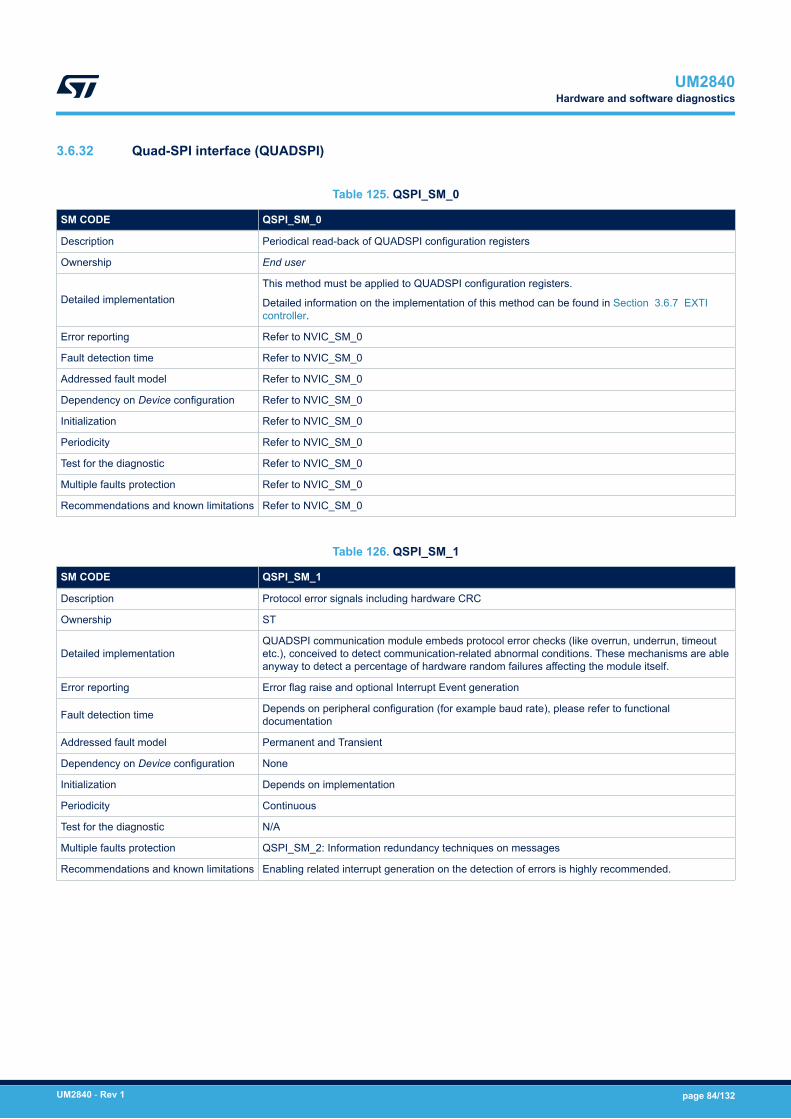
3.6.32 Quad-SPI interface (QUADSPI)
Table 125. QSPI_SM_0
SM CODE QSPI_SM_0
Description Periodical read-back of QUADSPI configuration registers
Ownership End user
Detailed implementationThis method must be applied to QUADSPI configuration registers.
Detailed information on the implementation of this method can be found in Section 3.6.7 EXTIcontroller.
Error reporting Refer to NVIC_SM_0
Fault detection time Refer to NVIC_SM_0
Addressed fault model Refer to NVIC_SM_0
Dependency on Device configuration Refer to NVIC_SM_0
Initialization Refer to NVIC_SM_0
Periodicity Refer to NVIC_SM_0
Test for the diagnostic Refer to NVIC_SM_0
Multiple faults protection Refer to NVIC_SM_0
Recommendations and known limitations Refer to NVIC_SM_0
Table 126. QSPI_SM_1
SM CODE QSPI_SM_1
Description Protocol error signals including hardware CRC
Ownership ST
Detailed implementationQUADSPI communication module embeds protocol error checks (like overrun, underrun, timeoutetc.), conceived to detect communication-related abnormal conditions. These mechanisms are ableanyway to detect a percentage of hardware random failures affecting the module itself.
Error reporting Error flag raise and optional Interrupt Event generation
Fault detection time Depends on peripheral configuration (for example baud rate), please refer to functionaldocumentation
Addressed fault model Permanent and Transient
Dependency on Device configuration None
Initialization Depends on implementation
Periodicity Continuous
Test for the diagnostic N/A
Multiple faults protection QSPI_SM_2: Information redundancy techniques on messages
Recommendations and known limitations Enabling related interrupt generation on the detection of errors is highly recommended.
UM2840Hardware and software diagnostics
UM2840 - Rev 1 page 84/132

Table 127. QSPI_SM_2
SM CODE QSPI_SM_2
Description Information redundancy techniques on messages
Ownership End user
Detailed implementation
This method is implemented adding to data packets (not commands) transferred by QSPI interfacea redundancy check (like a CRC check, or similar one) with encoding capability. The checksumencoding capability must be robust enough to guarantee at least 90% probability of detection for asingle bit flip and multi-bits flip in the data packet.
Consistency of data packet must be checked by the application software before consuming data
Error reporting Depends on implementation
Fault detection time Depends on implementation
Addressed fault model Permanent and Transient
Dependency on Device configuration None
Initialization Depends on implementation
Periodicity On demand
Test for the diagnostic Not needed
Multiple faults protection CPUM7_SM_0, CPUM4_SM_0: Periodical core self test software
Recommendations and knownlimitations
To give an example on checksum encoding capability, using just a bit-by-bit addition is unappropriated.
This safety mechanism can overlap with information redundancy techniques implemented at systemlevel to address failure of physical device connected to QSPI port
3.6.33 Serial audio interface (SAI)
Table 128. SAI_SM_0
SM CODE SAI_SM_0
Description Periodical read-back of SAI configuration registers
Ownership End user
Detailed implementationThis method must be applied to SAI configuration registers.
Detailed information on the implementation of this method can be found in Section 3.6.7 EXTIcontroller.
Error reporting Refer to NVIC_SM_0
Fault detection time Refer to NVIC_SM_0
Addressed fault model Refer to NVIC_SM_0
Dependency on Device configuration Refer to NVIC_SM_0
Initialization Refer to NVIC_SM_0
Periodicity Refer to NVIC_SM_0
Test for the diagnostic Refer to NVIC_SM_0
Multiple faults protection Refer to NVIC_SM_0
Recommendations and known limitations Refer to NVIC_SM_0
UM2840Hardware and software diagnostics
UM2840 - Rev 1 page 85/132
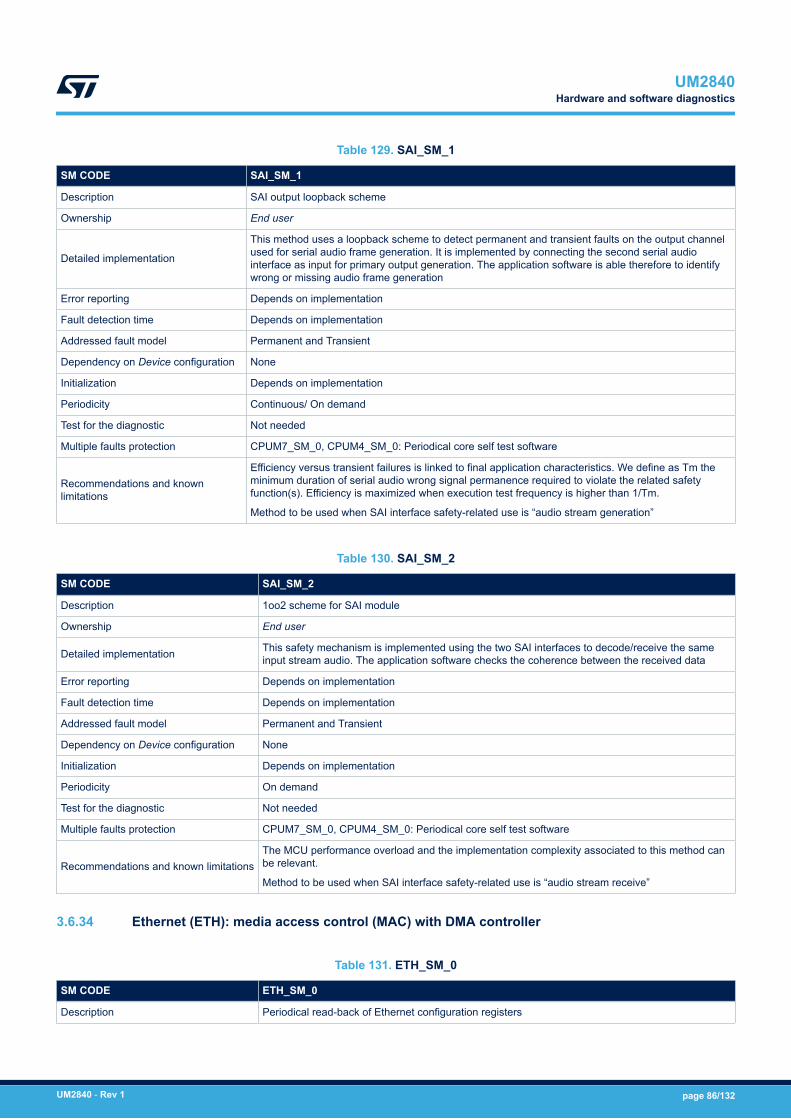
Table 129. SAI_SM_1
SM CODE SAI_SM_1
Description SAI output loopback scheme
Ownership End user
Detailed implementation
This method uses a loopback scheme to detect permanent and transient faults on the output channelused for serial audio frame generation. It is implemented by connecting the second serial audiointerface as input for primary output generation. The application software is able therefore to identifywrong or missing audio frame generation
Error reporting Depends on implementation
Fault detection time Depends on implementation
Addressed fault model Permanent and Transient
Dependency on Device configuration None
Initialization Depends on implementation
Periodicity Continuous/ On demand
Test for the diagnostic Not needed
Multiple faults protection CPUM7_SM_0, CPUM4_SM_0: Periodical core self test software
Recommendations and knownlimitations
Efficiency versus transient failures is linked to final application characteristics. We define as Tm theminimum duration of serial audio wrong signal permanence required to violate the related safetyfunction(s). Efficiency is maximized when execution test frequency is higher than 1/Tm.
Method to be used when SAI interface safety-related use is “audio stream generation”
Table 130. SAI_SM_2
SM CODE SAI_SM_2
Description 1oo2 scheme for SAI module
Ownership End user
Detailed implementation This safety mechanism is implemented using the two SAI interfaces to decode/receive the sameinput stream audio. The application software checks the coherence between the received data
Error reporting Depends on implementation
Fault detection time Depends on implementation
Addressed fault model Permanent and Transient
Dependency on Device configuration None
Initialization Depends on implementation
Periodicity On demand
Test for the diagnostic Not needed
Multiple faults protection CPUM7_SM_0, CPUM4_SM_0: Periodical core self test software
Recommendations and known limitationsThe MCU performance overload and the implementation complexity associated to this method canbe relevant.
Method to be used when SAI interface safety-related use is “audio stream receive”
3.6.34 Ethernet (ETH): media access control (MAC) with DMA controller
Table 131. ETH_SM_0
SM CODE ETH_SM_0
Description Periodical read-back of Ethernet configuration registers
UM2840Hardware and software diagnostics
UM2840 - Rev 1 page 86/132
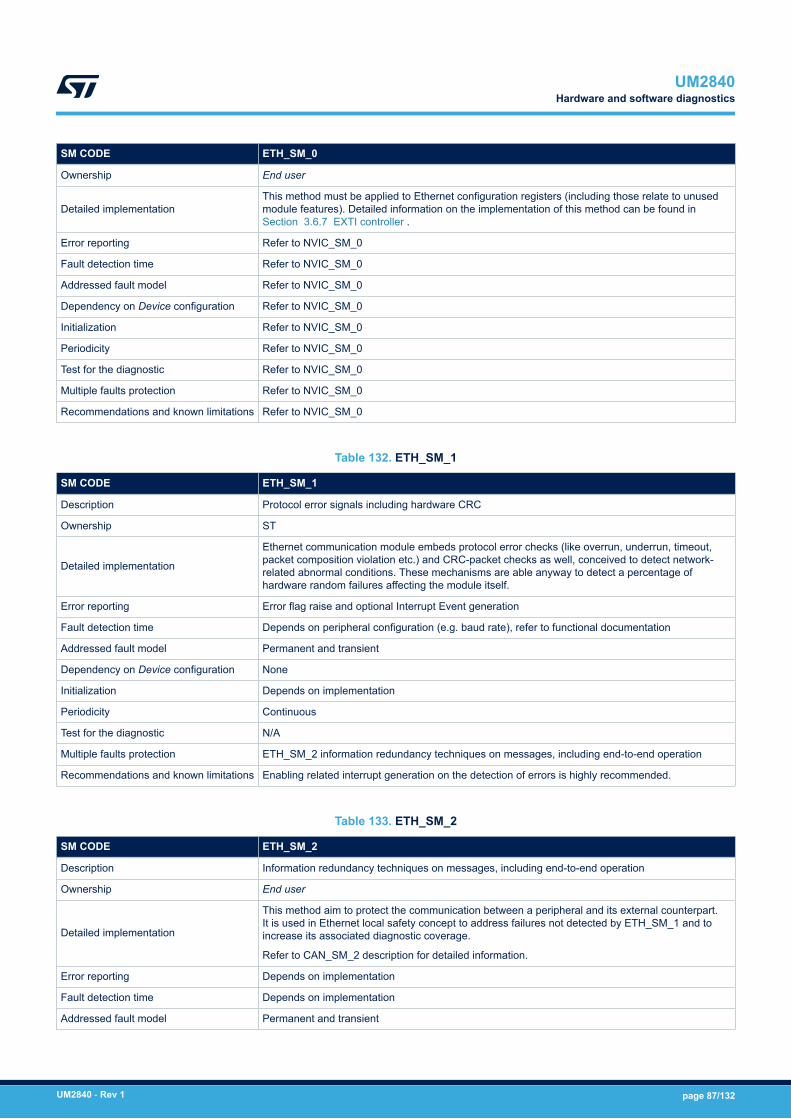
SM CODE ETH_SM_0
Ownership End user
Detailed implementationThis method must be applied to Ethernet configuration registers (including those relate to unusedmodule features). Detailed information on the implementation of this method can be found inSection 3.6.7 EXTI controller .
Error reporting Refer to NVIC_SM_0
Fault detection time Refer to NVIC_SM_0
Addressed fault model Refer to NVIC_SM_0
Dependency on Device configuration Refer to NVIC_SM_0
Initialization Refer to NVIC_SM_0
Periodicity Refer to NVIC_SM_0
Test for the diagnostic Refer to NVIC_SM_0
Multiple faults protection Refer to NVIC_SM_0
Recommendations and known limitations Refer to NVIC_SM_0
Table 132. ETH_SM_1
SM CODE ETH_SM_1
Description Protocol error signals including hardware CRC
Ownership ST
Detailed implementation
Ethernet communication module embeds protocol error checks (like overrun, underrun, timeout,packet composition violation etc.) and CRC-packet checks as well, conceived to detect network-related abnormal conditions. These mechanisms are able anyway to detect a percentage ofhardware random failures affecting the module itself.
Error reporting Error flag raise and optional Interrupt Event generation
Fault detection time Depends on peripheral configuration (e.g. baud rate), refer to functional documentation
Addressed fault model Permanent and transient
Dependency on Device configuration None
Initialization Depends on implementation
Periodicity Continuous
Test for the diagnostic N/A
Multiple faults protection ETH_SM_2 information redundancy techniques on messages, including end-to-end operation
Recommendations and known limitations Enabling related interrupt generation on the detection of errors is highly recommended.
Table 133. ETH_SM_2
SM CODE ETH_SM_2
Description Information redundancy techniques on messages, including end-to-end operation
Ownership End user
Detailed implementation
This method aim to protect the communication between a peripheral and its external counterpart.It is used in Ethernet local safety concept to address failures not detected by ETH_SM_1 and toincrease its associated diagnostic coverage.
Refer to CAN_SM_2 description for detailed information.
Error reporting Depends on implementation
Fault detection time Depends on implementation
Addressed fault model Permanent and transient
UM2840Hardware and software diagnostics
UM2840 - Rev 1 page 87/132

SM CODE ETH_SM_2
Dependency on Device configuration None
Initialization Depends on implementation
Periodicity On demand
Test for the diagnostic Not needed
Multiple faults protection CPUM7_SM_0, CPUM4_SM_0: periodical core self test software
Recommendations and known limitations The implementation on the application software of complex Ethernet-based communication stacks(like TCP/IP) is able to satisfy the requirements of this method.
Note: The use of the DMA feature inside Ethernet module brings to adopt the same set of safety mechanism definedfor the system DMA (refer to Section 3.6.8 Direct memory access controllers (DMA, MDMA, BDMA and DMArequest multiplexer (DMAMUX))).
3.6.35 JPEG codec (JPEG)
Table 134. JPEG_SM_0
SM CODE JPEG_SM_0
Description Periodical read-back of JPEG codec configuration registers.
Ownership End user
Detailed implementationThis method must be applied to JPEG codec configuration registers.
Detailed information on the implementation of this method can be found in Section 3.6.7 EXTIcontroller.
Error reporting Refer to NVIC_SM_0
Fault detection time Refer to NVIC_SM_0
Addressed fault model Refer to NVIC_SM_0
Dependency on Device configuration Refer to NVIC_SM_0
Initialization Refer to NVIC_SM_0
Periodicity Refer to NVIC_SM_0
Test for the diagnostic Refer to NVIC_SM_0
Multiple faults protection Refer to NVIC_SM_0
Recommendations and known limitations Refer to NVIC_SM_0
Table 135. JPEG_SM_1
SM CODE JPEG_SM_1
Description Periodic test for JPEG encoding/decoding functions
Ownership End user
Detailed implementation
JPEG encoding/decoding functions performed by JPEG codec are tested by comparison, executingthe functions over a set of reference images stored in the Flash memory and checking thecorrectness of output images. The method diagnostic coverage depends on the quantity andcomposition of image set used for the checks.
The comparison of output image with expected result can be executed bit-by-bit or even by fastermethods like CRC-seed (computed via DMA transactions) checks.
Error reporting Depends on implementation
Fault detection time Depends on implementation
Addressed fault model Permanent
UM2840Hardware and software diagnostics
UM2840 - Rev 1 page 88/132
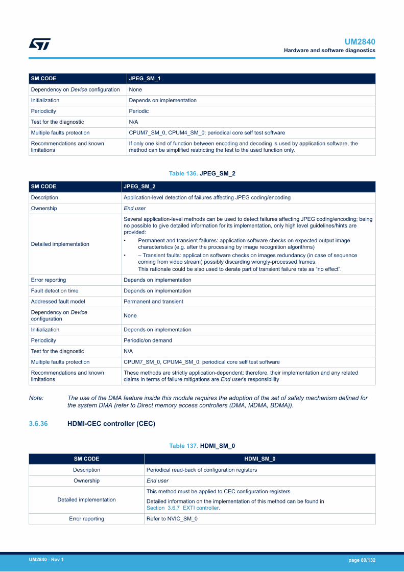
SM CODE JPEG_SM_1
Dependency on Device configuration None
Initialization Depends on implementation
Periodicity Periodic
Test for the diagnostic N/A
Multiple faults protection CPUM7_SM_0, CPUM4_SM_0: periodical core self test software
Recommendations and knownlimitations
If only one kind of function between encoding and decoding is used by application software, themethod can be simplified restricting the test to the used function only.
Table 136. JPEG_SM_2
SM CODE JPEG_SM_2
Description Application-level detection of failures affecting JPEG coding/encoding
Ownership End user
Detailed implementation
Several application-level methods can be used to detect failures affecting JPEG coding/encoding; beingno possible to give detailed information for its implementation, only high level guidelines/hints areprovided:• Permanent and transient failures: application software checks on expected output image
characteristics (e.g. after the processing by image recognition algorithms)• – Transient faults: application software checks on images redundancy (in case of sequence
coming from video stream) possibly discarding wrongly-processed frames.This rationale could be also used to derate part of transient failure rate as “no effect”.
Error reporting Depends on implementation
Fault detection time Depends on implementation
Addressed fault model Permanent and transient
Dependency on Deviceconfiguration None
Initialization Depends on implementation
Periodicity Periodic/on demand
Test for the diagnostic N/A
Multiple faults protection CPUM7_SM_0, CPUM4_SM_0: periodical core self test software
Recommendations and knownlimitations
These methods are strictly application-dependent; therefore, their implementation and any relatedclaims in terms of failure mitigations are End user’s responsibility
Note: The use of the DMA feature inside this module requires the adoption of the set of safety mechanism defined forthe system DMA (refer to Direct memory access controllers (DMA, MDMA, BDMA)).
3.6.36 HDMI-CEC controller (CEC)
Table 137. HDMI_SM_0
SM CODE HDMI_SM_0
Description Periodical read-back of configuration registers
Ownership End user
Detailed implementationThis method must be applied to CEC configuration registers.
Detailed information on the implementation of this method can be found inSection 3.6.7 EXTI controller.
Error reporting Refer to NVIC_SM_0
UM2840Hardware and software diagnostics
UM2840 - Rev 1 page 89/132
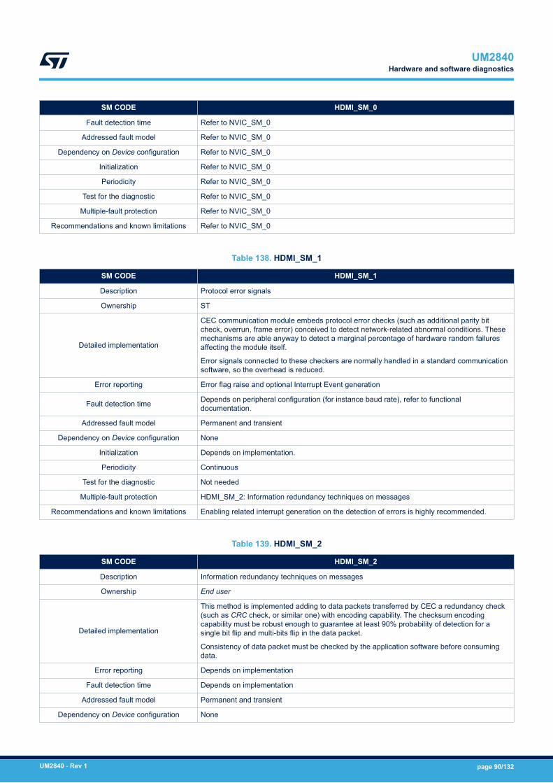
SM CODE HDMI_SM_0
Fault detection time Refer to NVIC_SM_0
Addressed fault model Refer to NVIC_SM_0
Dependency on Device configuration Refer to NVIC_SM_0
Initialization Refer to NVIC_SM_0
Periodicity Refer to NVIC_SM_0
Test for the diagnostic Refer to NVIC_SM_0
Multiple-fault protection Refer to NVIC_SM_0
Recommendations and known limitations Refer to NVIC_SM_0
Table 138. HDMI_SM_1
SM CODE HDMI_SM_1
Description Protocol error signals
Ownership ST
Detailed implementation
CEC communication module embeds protocol error checks (such as additional parity bitcheck, overrun, frame error) conceived to detect network-related abnormal conditions. Thesemechanisms are able anyway to detect a marginal percentage of hardware random failuresaffecting the module itself.
Error signals connected to these checkers are normally handled in a standard communicationsoftware, so the overhead is reduced.
Error reporting Error flag raise and optional Interrupt Event generation
Fault detection time Depends on peripheral configuration (for instance baud rate), refer to functionaldocumentation.
Addressed fault model Permanent and transient
Dependency on Device configuration None
Initialization Depends on implementation.
Periodicity Continuous
Test for the diagnostic Not needed
Multiple-fault protection HDMI_SM_2: Information redundancy techniques on messages
Recommendations and known limitations Enabling related interrupt generation on the detection of errors is highly recommended.
Table 139. HDMI_SM_2
SM CODE HDMI_SM_2
Description Information redundancy techniques on messages
Ownership End user
Detailed implementation
This method is implemented adding to data packets transferred by CEC a redundancy check(such as CRC check, or similar one) with encoding capability. The checksum encodingcapability must be robust enough to guarantee at least 90% probability of detection for asingle bit flip and multi-bits flip in the data packet.
Consistency of data packet must be checked by the application software before consumingdata.
Error reporting Depends on implementation
Fault detection time Depends on implementation
Addressed fault model Permanent and transient
Dependency on Device configuration None
UM2840Hardware and software diagnostics
UM2840 - Rev 1 page 90/132
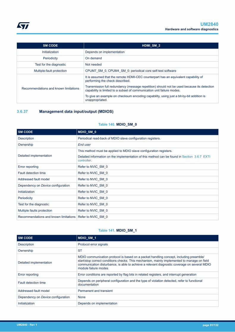
SM CODE HDMI_SM_2
Initialization Depends on implementation
Periodicity On demand
Test for the diagnostic Not needed
Multiple-fault protection CPUM7_SM_0, CPUM4_SM_0: periodical core self-test software
Recommendations and known limitations
It is assumed that the remote HDMI-CEC counterpart has an equivalent capability ofperforming the check described.
Transmission full redundancy (message repetition) should not be used because its detectioncapability is limited to a subset of communication unit failure modes.
To give an example on checksum encoding capability, using just a bit-by-bit addition isunappropriated.
3.6.37 Management data input/output (MDIOS)
Table 140. MDIO_SM_0
SM CODE MDIO_SM_0
Description Periodical read-back of MDIO slave configuration registers.
Ownership End user
Detailed implementationThis method must be applied to MDIO slave configuration registers.
Detailed information on the implementation of this method can be found in Section 3.6.7 EXTIcontroller.
Error reporting Refer to NVIC_SM_0
Fault detection time Refer to NVIC_SM_0
Addressed fault model Refer to NVIC_SM_0
Dependency on Device configuration Refer to NVIC_SM_0
Initialization Refer to NVIC_SM_0
Periodicity Refer to NVIC_SM_0
Test for the diagnostic Refer to NVIC_SM_0
Multiple faults protection Refer to NVIC_SM_0
Recommendations and known limitations Refer to NVIC_SM_0
Table 141. MDIO_SM_1
SM CODE MDIO_SM_1
Description Protocol error signals
Ownership ST
Detailed implementation
MDIO communication protocol is based on a packet handling concept, including preamble/start/stop correct conditions checks. This mechanism, mainly implemented to manage on fieldcommunication disturbance, is able to achieve a relevant diagnostic coverage on several MDIOmodule failure modes
Error reporting Error conditions are reported by flag bits in related registers, and interrupt generation
Fault detection time Depends on peripheral configuration and the type of violation detected, refer to functionaldocumentation
Addressed fault model Permanent and transient
Dependency on Device configuration None
Initialization Depends on implementation
UM2840Hardware and software diagnostics
UM2840 - Rev 1 page 91/132

SM CODE MDIO_SM_1
Periodicity Continuous
Test for the diagnostic N/A
Multiple faults protection MDIO_SM_0: periodical read-back of MDIO Host configuration registers.
Recommendations and known limitations -
Table 142. MDIO_SM_2
SM CODE MDIO_SM_2
Description Information redundancy techniques on MDIO registers contents, including register update awareness.
Ownership End user
Detailed implementation
Information provided by external parties by MDIO communication must be protected by redundancyschemes (encoded data values and possibly the definition of a “checksum” register).
The application software must be aware of any register value update executed by external parties, so itis needed the implementation of a “validate/unvalidate” mechanism to:• report to external party that updated data have been consumed• mark as “unvalidated” any data already consumed• allow external party to inform application software that new data are available
Error reporting Depends on implementation
Fault detection time Depends on implementation
Addressed fault model Permanent and transient
Dependency on Deviceconfiguration None
Initialization Depends on implementation
Periodicity On demand
Test for the diagnostic Not needed
Multiple faults protection CPUM7_SM_0, CPUM4_SM_0: periodical core self test software
Recommendations and knownlimitations
It is assumed that the external entity responsible to update/send data to application software by theMDIO communication link is able to contribute to the MDIO failure mitigation, by detecting missing orincomplete data consumption.
3.6.38 SPDIF receiver interface (SPDIFRX)
Table 143. SPDF_SM_0
SM CODE SPDF_SM_0
Description Periodical read-back of SPDIF configuration registers
Ownership End user
Detailed implementationThis method must be applied to SPDIF configuration registers.
Detailed information on the implementation of this method can be found in section NVIC_SM_0
Error reporting Refer to NVIC_SM_0
Fault detection time Refer to NVIC_SM_0
Addressed fault model Refer to NVIC_SM_0
Dependency on Device configuration Refer to NVIC_SM_0
Initialization Refer to NVIC_SM_0
Periodicity Refer to NVIC_SM_0
UM2840Hardware and software diagnostics
UM2840 - Rev 1 page 92/132
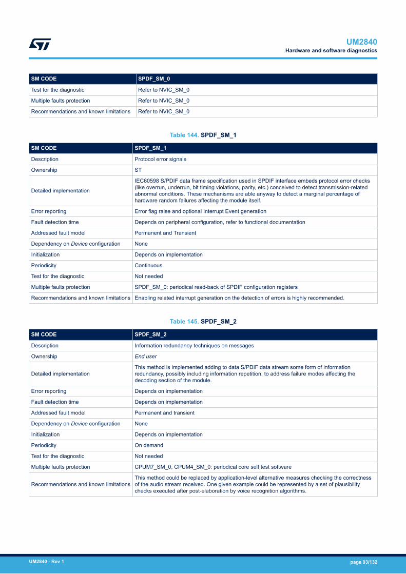
SM CODE SPDF_SM_0
Test for the diagnostic Refer to NVIC_SM_0
Multiple faults protection Refer to NVIC_SM_0
Recommendations and known limitations Refer to NVIC_SM_0
Table 144. SPDF_SM_1
SM CODE SPDF_SM_1
Description Protocol error signals
Ownership ST
Detailed implementation
IEC60598 S/PDIF data frame specification used in SPDIF interface embeds protocol error checks(like overrun, underrun, bit timing violations, parity, etc.) conceived to detect transmission-relatedabnormal conditions. These mechanisms are able anyway to detect a marginal percentage ofhardware random failures affecting the module itself.
Error reporting Error flag raise and optional Interrupt Event generation
Fault detection time Depends on peripheral configuration, refer to functional documentation
Addressed fault model Permanent and Transient
Dependency on Device configuration None
Initialization Depends on implementation
Periodicity Continuous
Test for the diagnostic Not needed
Multiple faults protection SPDF_SM_0: periodical read-back of SPDIF configuration registers
Recommendations and known limitations Enabling related interrupt generation on the detection of errors is highly recommended.
Table 145. SPDF_SM_2
SM CODE SPDF_SM_2
Description Information redundancy techniques on messages
Ownership End user
Detailed implementationThis method is implemented adding to data S/PDIF data stream some form of informationredundancy, possibly including information repetition, to address failure modes affecting thedecoding section of the module.
Error reporting Depends on implementation
Fault detection time Depends on implementation
Addressed fault model Permanent and transient
Dependency on Device configuration None
Initialization Depends on implementation
Periodicity On demand
Test for the diagnostic Not needed
Multiple faults protection CPUM7_SM_0, CPUM4_SM_0: periodical core self test software
Recommendations and known limitationsThis method could be replaced by application-level alternative measures checking the correctnessof the audio stream received. One given example could be represented by a set of plausibilitychecks executed after post-elaboration by voice recognition algorithms.
UM2840Hardware and software diagnostics
UM2840 - Rev 1 page 93/132

3.6.39 True random number generator (RNG)
Table 146. RNG_SM_0
SM CODE RNG_SM_0
Description Periodical read-back of RNG configuration register RNG_CR
Ownership End user
Detailed implementationThis method must be applied to RNG configuration registers.
Detailed information on the implementation of this method can be found inSection 3.6.7 EXTI controller.
Error reporting Refer to NVIC_SM_0
Fault detection time Refer to NVIC_SM_0
Addressed fault model Refer to NVIC_SM_0
Dependency on Device configuration RNG module available only on specific part numbers
Initialization Refer to NVIC_SM_0
Periodicity Refer to NVIC_SM_0
Test for the diagnostic Refer to NVIC_SM_0
Multiple-fault protection Refer to NVIC_SM_0
Recommendations and known limitations Refer to NVIC_SM_0
Table 147. RNG_SM_1
SM CODE RNG_SM_1
Description RNG module entropy on-line tests
Ownership ST and End user
Detailed implementation
RNG module include an internal diagnostic for the analog source entropy that can be usedto detect failures on the module itself. Furthermore, the required test on generated randomnumber difference between the previous one (as required by FIPS PUB 140-2) can beexploited as well.
Implementation:• Check for RNG error conditions.• Check the difference between generated random number and the previous one.
Error reportingCEIS, SEIS error bits in RNG status register (RNG_SR)
Application software error for FIPS PUB 140-2 test fail
Fault detection time Depends on implementation.
Addressed fault model Permanent and transient
Dependency on Device configuration RNG module available only on specific part numbers
Initialization Depends on implementation.
Periodicity Continuous
Test for the diagnostic N/A
Multiple-fault protection CPUM7_SM_0, CPUM4_SM_0: Periodical core self test software
Recommendations and known limitations -
UM2840Hardware and software diagnostics
UM2840 - Rev 1 page 94/132

3.6.40 Cryptographic processor (CRYP)
Table 148. AES_SM_0
SM CODE AES_SM_0
Description Periodical read-back of CRYP configuration registers
Ownership End user
Detailed implementationThis method must be applied to CRYP configuration registers.
Detailed information on the implementation of this method can be found inSection 3.6.7 EXTI controller.
Error reporting Refer to NVIC_SM_0
Fault detection time Refer to NVIC_SM_0
Addressed fault model Refer to NVIC_SM_0
Dependency on Device configuration CRYP module available only on specific part numbers
Initialization Refer to NVIC_SM_0
Periodicity Refer to NVIC_SM_0
Test for the diagnostic Refer to NVIC_SM_0
Multiple faults protection Refer to NVIC_SM_0
Recommendations and known limitations Refer to NVIC_SM_0
Table 149. AES_SM_1
SM CODE AES_SM_1
Description Encryption/decryption collateral detection
Ownership ST
Detailed implementation
Encryption and decryption operations performed by CRYP module are composed by severaldata manipulations and checks, with different level of complexity according to the selectedchaining algorithm. A major part of the hardware random failures affecting CRYP moduleleads to algorithm violations/errors. Leading to decoding errors on the receiver side.
Error reporting Several error conditions can happen, check functional documentation.
Fault detection time Depends on peripheral configuration
Addressed fault model Permanent and Transient
Dependency on Device configuration CRYP module available only on specific part numbers
Initialization Depends on implementation.
Periodicity Continuous
Test for the diagnostic N/A
Multiple faults protection AES_SM_2: Information redundancy techniques on messages
Recommendations and known limitations -
Table 150. AES_SM_2
SM CODE AES_SM_2
Description Information redundancy techniques on messages, including end-to-end protection.
Ownership End user
UM2840Hardware and software diagnostics
UM2840 - Rev 1 page 95/132
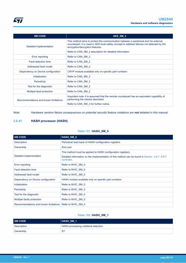
SM CODE AES_SM_2
Detailed implementation
This method aims to protect the communication between a peripheral and his externalcounterpart. It is used in AES local safety concept to address failures not detected by theencryption/decryption features.
Refer to CAN_SM_2 description for detailed information.
Error reporting Refer to CAN_SM_2
Fault detection time Refer to CAN_SM_2
Addressed fault model Refer to CAN_SM_2
Dependency on Device configuration CRYP module available only on specific part numbers
Initialization Refer to CAN_SM_2
Periodicity Refer to CAN_SM_2
Test for the diagnostic Refer to CAN_SM_2
Multiple-fault protection Refer to CAN_SM_2
Recommendations and known limitationsImportant note: it is assumed that the remote counterpart has an equivalent capability ofperforming the checks described.
Refer to CAN_SM_2 for further notice.
Note: Hardware random failure consequences on potential security feature violations are not detailed in this manual.
3.6.41 HASH processor (HASH)
Table 151. HASH_SM_0
SM CODE HASH_SM_0
Description Periodical read-back of HASH configuration registers
Ownership End user
Detailed implementationThis method must be applied to HASH configuration registers.
Detailed information on the implementation of this method can be found in Section 3.6.7 EXTIcontroller.
Error reporting Refer to NVIC_SM_0
Fault detection time Refer to NVIC_SM_0
Addressed fault model Refer to NVIC_SM_0
Dependency on Device configuration HASH module available only on specific part numbers
Initialization Refer to NVIC_SM_0
Periodicity Refer to NVIC_SM_0
Test for the diagnostic Refer to NVIC_SM_0
Multiple faults protection Refer to NVIC_SM_0
Recommendations and known limitations Refer to NVIC_SM_0
Table 152. HASH_SM_1
SM CODE HASH_SM_1
Description HASH processing collateral detection
Ownership ST
UM2840Hardware and software diagnostics
UM2840 - Rev 1 page 96/132
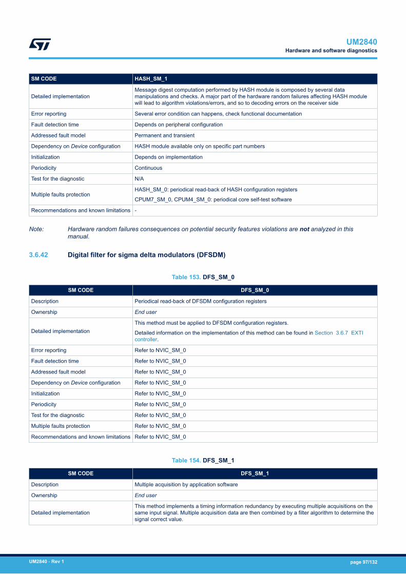
SM CODE HASH_SM_1
Detailed implementationMessage digest computation performed by HASH module is composed by several datamanipulations and checks. A major part of the hardware random failures affecting HASH modulewill lead to algorithm violations/errors, and so to decoding errors on the receiver side
Error reporting Several error condition can happens, check functional documentation
Fault detection time Depends on peripheral configuration
Addressed fault model Permanent and transient
Dependency on Device configuration HASH module available only on specific part numbers
Initialization Depends on implementation
Periodicity Continuous
Test for the diagnostic N/A
Multiple faults protectionHASH_SM_0: periodical read-back of HASH configuration registers
CPUM7_SM_0, CPUM4_SM_0: periodical core self-test software
Recommendations and known limitations -
Note: Hardware random failures consequences on potential security features violations are not analyzed in thismanual.
3.6.42 Digital filter for sigma delta modulators (DFSDM)
Table 153. DFS_SM_0
SM CODE DFS_SM_0
Description Periodical read-back of DFSDM configuration registers
Ownership End user
Detailed implementationThis method must be applied to DFSDM configuration registers.
Detailed information on the implementation of this method can be found in Section 3.6.7 EXTIcontroller.
Error reporting Refer to NVIC_SM_0
Fault detection time Refer to NVIC_SM_0
Addressed fault model Refer to NVIC_SM_0
Dependency on Device configuration Refer to NVIC_SM_0
Initialization Refer to NVIC_SM_0
Periodicity Refer to NVIC_SM_0
Test for the diagnostic Refer to NVIC_SM_0
Multiple faults protection Refer to NVIC_SM_0
Recommendations and known limitations Refer to NVIC_SM_0
Table 154. DFS_SM_1
SM CODE DFS_SM_1
Description Multiple acquisition by application software
Ownership End user
Detailed implementationThis method implements a timing information redundancy by executing multiple acquisitions on thesame input signal. Multiple acquisition data are then combined by a filter algorithm to determine thesignal correct value.
UM2840Hardware and software diagnostics
UM2840 - Rev 1 page 97/132
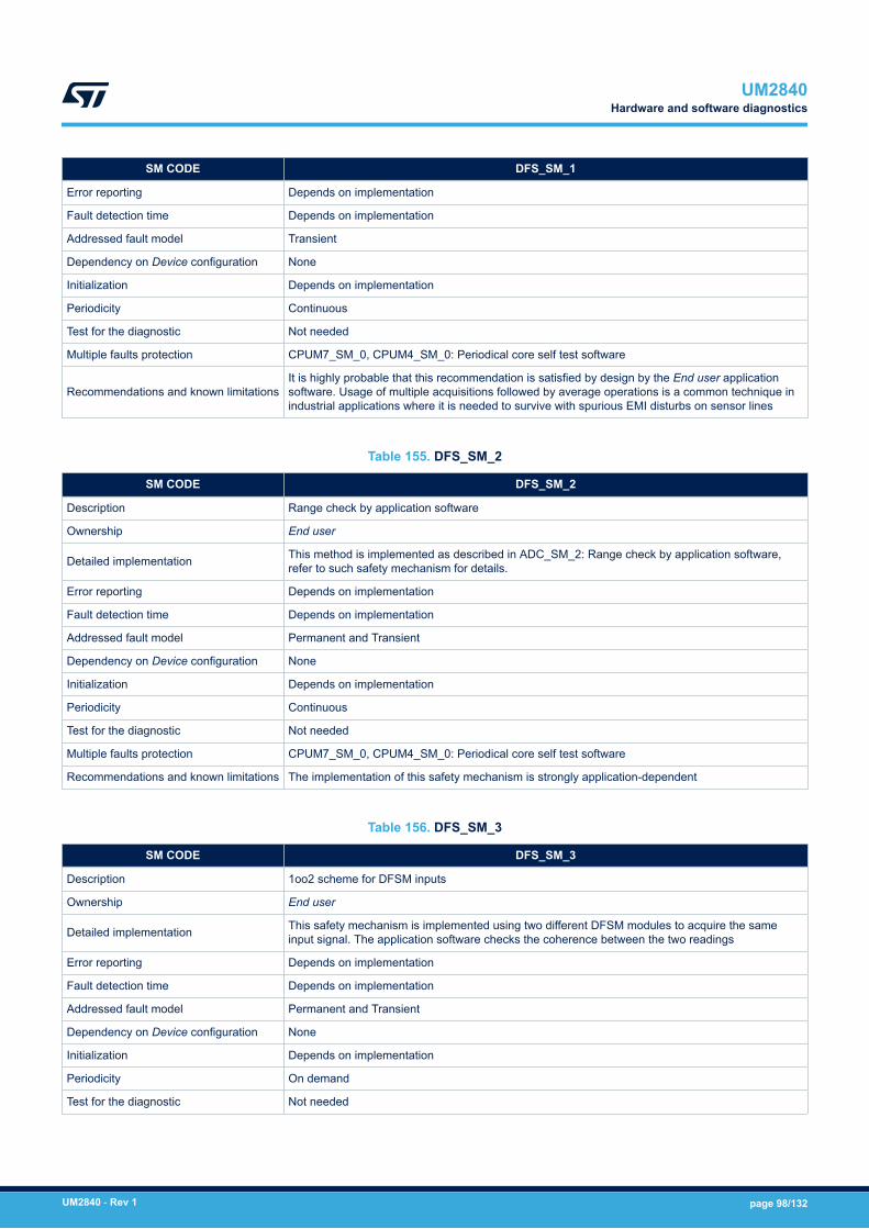
SM CODE DFS_SM_1
Error reporting Depends on implementation
Fault detection time Depends on implementation
Addressed fault model Transient
Dependency on Device configuration None
Initialization Depends on implementation
Periodicity Continuous
Test for the diagnostic Not needed
Multiple faults protection CPUM7_SM_0, CPUM4_SM_0: Periodical core self test software
Recommendations and known limitationsIt is highly probable that this recommendation is satisfied by design by the End user applicationsoftware. Usage of multiple acquisitions followed by average operations is a common technique inindustrial applications where it is needed to survive with spurious EMI disturbs on sensor lines
Table 155. DFS_SM_2
SM CODE DFS_SM_2
Description Range check by application software
Ownership End user
Detailed implementation This method is implemented as described in ADC_SM_2: Range check by application software,refer to such safety mechanism for details.
Error reporting Depends on implementation
Fault detection time Depends on implementation
Addressed fault model Permanent and Transient
Dependency on Device configuration None
Initialization Depends on implementation
Periodicity Continuous
Test for the diagnostic Not needed
Multiple faults protection CPUM7_SM_0, CPUM4_SM_0: Periodical core self test software
Recommendations and known limitations The implementation of this safety mechanism is strongly application-dependent
Table 156. DFS_SM_3
SM CODE DFS_SM_3
Description 1oo2 scheme for DFSM inputs
Ownership End user
Detailed implementation This safety mechanism is implemented using two different DFSM modules to acquire the sameinput signal. The application software checks the coherence between the two readings
Error reporting Depends on implementation
Fault detection time Depends on implementation
Addressed fault model Permanent and Transient
Dependency on Device configuration None
Initialization Depends on implementation
Periodicity On demand
Test for the diagnostic Not needed
UM2840Hardware and software diagnostics
UM2840 - Rev 1 page 98/132
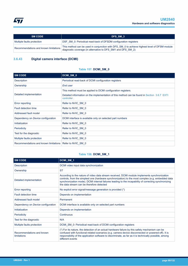
SM CODE DFS_SM_3
Multiple faults protection DSF_SM_0: Periodical read-back of DFSDM configuration registers
Recommendations and known limitations This method can be used in conjunction with DFS_SM_0 to achieve highest level of DFSM modulediagnostic coverage (in alternative to DFS_SM1 and DFS_SM_2)
3.6.43 Digital camera interface (DCMI)
Table 157. DCMI_SM_0
SM CODE DCMI_SM_0
Description Periodical read-back of DCMI configuration registers
Ownership End user
Detailed implementationThis method must be applied to DCMI configuration registers.
Detailed information on the implementation of this method can be found in Section 3.6.7 EXTIcontroller .
Error reporting Refer to NVIC_SM_0
Fault detection time Refer to NVIC_SM_0
Addressed fault model Refer to NVIC_SM_0
Dependency on Device configuration DCMI interface is available only on selected part numbers
Initialization Refer to NVIC_SM_0
Periodicity Refer to NVIC_SM_0
Test for the diagnostic Refer to NVIC_SM_0
Multiple faults protection Refer to NVIC_SM_0
Recommendations and known limitations Refer to NVIC_SM_0
Table 158. DCMI_SM_1
SM CODE DCMI_SM_1
Description DCMI video input data synchronization
Ownership ST
Detailed implementation
According to the nature of video data stream received, DCMI module implements synchronizationcontrols, from the simplest one (hardware synchronization) to the most complex (e.g. embedded datasynchronization mode). DCMI internal failures leading to the incapability of correcting synchronizingthe data stream can be therefore detected
Error reporting No explicit error signal/message generation is provided (*)
Fault detection time Depends on implementation
Addressed fault model Permanent
Dependency on Device configuration DCMI interface is available only on selected part numbers
Initialization Depends on implementation
Periodicity Continuous
Test for the diagnostic N/A
Multiple faults protection DCMI_SM_0: Periodical read-back of DCMI configuration registers
Recommendations and knownlimitations
(*) For its nature, the detection of an actual hardware failure by this safety mechanism can beconfused with functional-related scenarios (e.g. camera device disconnected or powered-off). It isresponsibility of the application software to discriminate, as far as it is technically possible, amongdifferent events
UM2840Hardware and software diagnostics
UM2840 - Rev 1 page 99/132
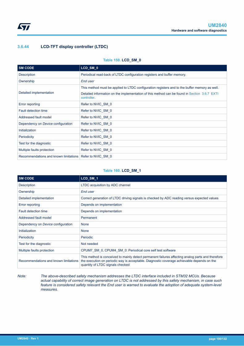
3.6.44 LCD-TFT display controller (LTDC)
Table 159. LCD_SM_0
SM CODE LCD_SM_0
Description Periodical read-back of LTDC configuration registers and buffer memory.
Ownership End user
Detailed implementationThis method must be applied to LTDC configuration registers and to the buffer memory as well.
Detailed information on the implementation of this method can be found in Section 3.6.7 EXTIcontroller.
Error reporting Refer to NVIC_SM_0
Fault detection time Refer to NVIC_SM_0
Addressed fault model Refer to NVIC_SM_0
Dependency on Device configuration Refer to NVIC_SM_0
Initialization Refer to NVIC_SM_0
Periodicity Refer to NVIC_SM_0
Test for the diagnostic Refer to NVIC_SM_0
Multiple faults protection Refer to NVIC_SM_0
Recommendations and known limitations Refer to NVIC_SM_0
Table 160. LCD_SM_1
SM CODE LCD_SM_1
Description LTDC acquisition by ADC channel
Ownership End user
Detailed implementation Correct generation of LTDC driving signals is checked by ADC reading versus expected values
Error reporting Depends on implementation
Fault detection time Depends on implementation
Addressed fault model Permanent
Dependency on Device configuration None
Initialization None
Periodicity Periodic
Test for the diagnostic Not needed
Multiple faults protection CPUM7_SM_0, CPUM4_SM_0: Periodical core self test software
Recommendations and known limitationsThis method is conceived to mainly detect permanent failures affecting analog parts and thereforethe execution on periodic way is acceptable. Diagnostic coverage achievable depends on thequantity of LTDC signals checked
Note: The above-described safety mechanism addresses the LTDC interface included in STM32 MCUs. Becauseactual capability of correct image generation on LTDC is not addressed by this safety mechanism, in case suchfeature is considered safety relevant the End user is warned to evaluate the adoption of adequate system-levelmeasures.
UM2840Hardware and software diagnostics
UM2840 - Rev 1 page 100/132

3.6.45 Comparator (COMP)
Table 161. COMP_SM_0
SM CODE COMP_SM_0
Description Periodical read-back of configuration registers
Ownership End user
Detailed implementationThis method must be applied to COMP configuration registers.
Detailed information on the implementation of this method can be found inSection 3.6.7 EXTI controller.
Error reporting Refer to NVIC_SM_0
Fault detection time Refer to NVIC_SM_0
Addressed fault model Refer to NVIC_SM_0
Dependency on Device configuration Refer to NVIC_SM_0
Initialization Refer to NVIC_SM_0
Periodicity Refer to NVIC_SM_0
Test for the diagnostic Refer to NVIC_SM_0
Multiple-fault protection Refer to NVIC_SM_0
Recommendations and known limitations Refer to NVIC_SM_0
Table 162. COMP_SM_1
SM CODE COMP_SM_1
Description 1oo2 scheme for comparator
Ownership End user
Detailed implementation This safety mechanism is implemented using the two internal comparators to take the samedecision. It requires that the comparator voting is handled accordingly.
Error reporting Depends on implementation
Fault detection time Depends on implementation
Addressed fault model Permanent and transient
Dependency on Device configuration None
Initialization Depends on implementation
Periodicity On demand
Test for the diagnostic Not needed
Multiple-fault protection CPUM7_SM_0, CPUM4_SM_0: periodical core self-test software
Recommendations and known limitations This method is not compatible with “window” comparator feature.
Table 163. COMP_SM_2
SM CODE COMP_SM_2
Description Plausibility check on inputs
Ownership End user
Detailed implementationThis method is used to redundantly acquire on dedicated ADC channels the analog inputsthat are subjected to comparator function, and to periodically check the coherence of thecomparator output on the measured values.
UM2840Hardware and software diagnostics
UM2840 - Rev 1 page 101/132

SM CODE COMP_SM_2
Error reporting Depends on implementation
Fault detection time Depends on implementation
Addressed fault model Permanent
Dependency on Device configuration None
Initialization Depends on implementation
Periodicity Periodic
Test for the diagnostic Not needed
Multiple-fault protection CPUM7_SM_0, CPUM4_SM_0: periodical core self-test software
Recommendations and known limitations None
Table 164. COMP_SM_3
SM CODE COMP_SM_3
Description Multiple acquisition by application software
Ownership End user
Detailed implementationThis method requires that application software takes a decision not on the basis of acomparator single-shot transition, but after multiple events or after the permanence ofcomparator trigger conditions for a certain amount of time.
Error reporting Depends on implementation
Fault detection time Depends on implementation
Addressed fault model Transient
Dependency on Device configuration None
Initialization Depends on implementation
Periodicity On demand
Test for the diagnostic Not needed
Multiple-fault protection CPUM7_SM_0, CPUM4_SM_0: periodical core self-test software
Recommendations and known limitationsIt is highly probable that this recommendation is satisfied by design on End user application- multiple acquisition is a common technique in industrial applications facing electromagneticinterference on sensor lines.
Table 165. COMP_SM_4
SM CODE COMP_SM_4
Description Comparator Lock mechanism
Ownership ST
Detailed implementation This safety mechanism prevents configuration changes for comparator control and statusregisters; it addresses therefore systematic faults in the software application.
Error reporting NA
Fault detection time NA
Addressed fault model None (Fault avoidance)
Dependency on Device configuration None
Initialization Lock protection must be enabled through the COMPxLOCK bits of the COMP_CSR register.
Periodicity Continuous
Test for the diagnostic NA
UM2840Hardware and software diagnostics
UM2840 - Rev 1 page 102/132
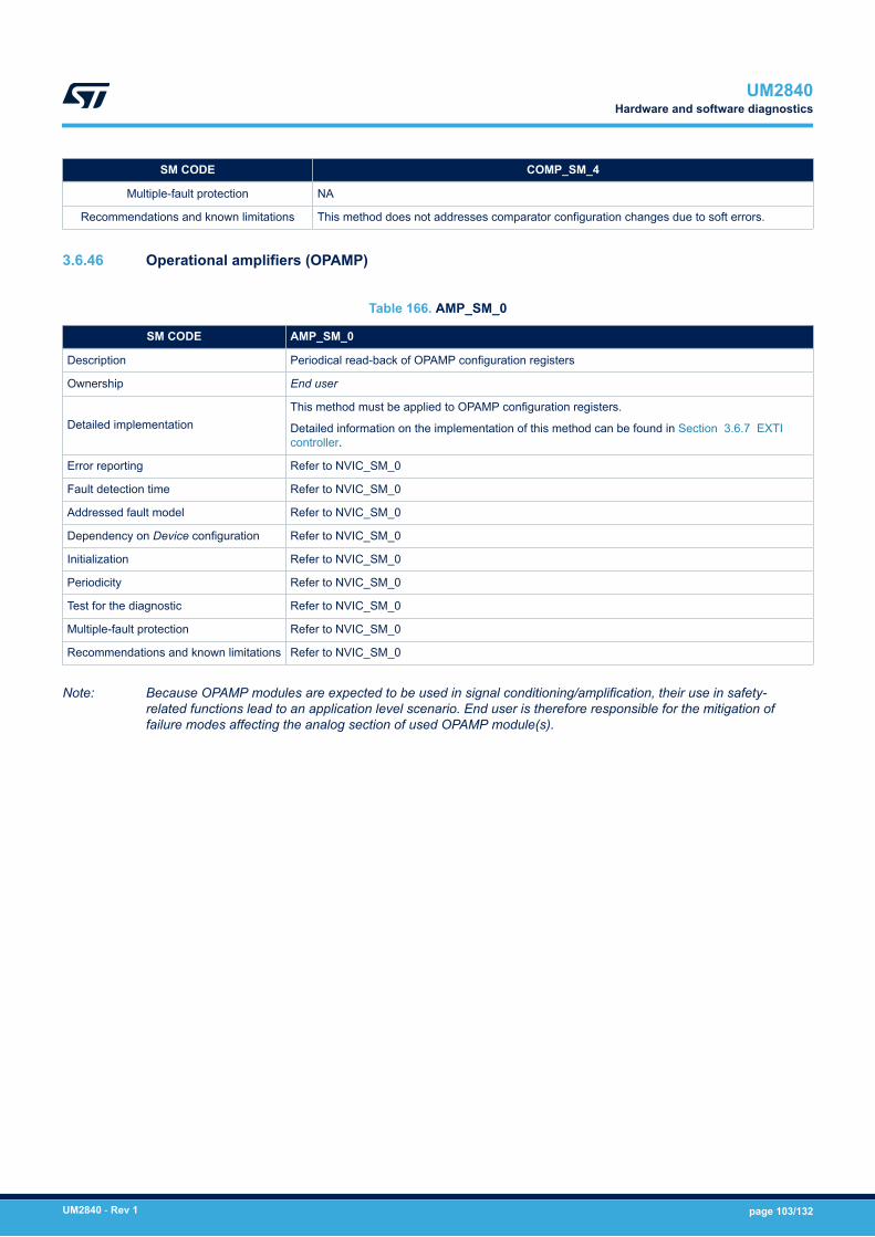
SM CODE COMP_SM_4
Multiple-fault protection NA
Recommendations and known limitations This method does not addresses comparator configuration changes due to soft errors.
3.6.46 Operational amplifiers (OPAMP)
Table 166. AMP_SM_0
SM CODE AMP_SM_0
Description Periodical read-back of OPAMP configuration registers
Ownership End user
Detailed implementationThis method must be applied to OPAMP configuration registers.
Detailed information on the implementation of this method can be found in Section 3.6.7 EXTIcontroller.
Error reporting Refer to NVIC_SM_0
Fault detection time Refer to NVIC_SM_0
Addressed fault model Refer to NVIC_SM_0
Dependency on Device configuration Refer to NVIC_SM_0
Initialization Refer to NVIC_SM_0
Periodicity Refer to NVIC_SM_0
Test for the diagnostic Refer to NVIC_SM_0
Multiple-fault protection Refer to NVIC_SM_0
Recommendations and known limitations Refer to NVIC_SM_0
Note: Because OPAMP modules are expected to be used in signal conditioning/amplification, their use in safety-related functions lead to an application level scenario. End user is therefore responsible for the mitigation offailure modes affecting the analog section of used OPAMP module(s).
UM2840Hardware and software diagnostics
UM2840 - Rev 1 page 103/132

3.6.47 Delay block (DLYB)
Table 167. DLB_SM_0
SM CODE DLB_SM_0
Description Periodical read-back of DLYB configuration registers
Ownership End user
Detailed implementationThis method must be applied to DLYB configuration registers.
Detailed information on the implementation of this method can be found in Section 3.6.7 EXTIcontroller
Error reporting Refer to NVIC_SM_0
Fault detection time Refer to NVIC_SM_0
Addressed fault model Refer to NVIC_SM_0
Dependency on Device configuration Refer to NVIC_SM_0
Initialization Refer to NVIC_SM_0
Periodicity Refer to NVIC_SM_0
Test for the diagnostic Refer to NVIC_SM_0
Multiple-fault protection Refer to NVIC_SM_0
Recommendations and known limitations Refer to NVIC_SM_0
Note: It is assumed that DLYB output, if used, feeds STM32H7 internal communication peripherals (like, for instance,QUADSPI). It is also assumed that for the connected peripherals all prescript safety mechanisms (rated as ++and +) are correctly implemented.
3.6.48 Voltage reference buffer (VREFBUF)
Table 168. VREF_SM_0
SM CODE VREF_SM_0
Description Periodical read-back of VREFBUF system configuration registers
Ownership End user
Detailed implementationThis method must be applied to VREFBUF configuration registers.
Detailed information on the implementation of this method can be found inSection 3.6.7 EXTI controller.
Error reporting Refer to NVIC_SM_0
Fault detection time Refer to NVIC_SM_0
Addressed fault model Refer to NVIC_SM_0
Dependency on MCU configuration Refer to NVIC_SM_0
Initialization Refer to NVIC_SM_0
Periodicity Refer to NVIC_SM_0
Test for the diagnostic Refer to NVIC_SM_0
Multiple faults protection CPUM7_SM_0, CPUM4_SM_0: Periodical core self test software
Recommendations and known limitations Refer to NVIC_SM_0
UM2840Hardware and software diagnostics
UM2840 - Rev 1 page 104/132
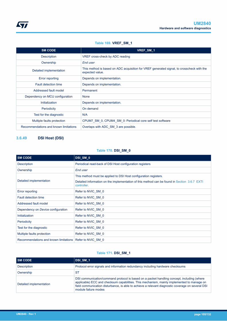
Table 169. VREF_SM_1
SM CODE VREF_SM_1
Description VREF cross-check by ADC reading
Ownership End user
Detailed implementation This method is based on ADC acquisition for VREF generated signal, to crosscheck with theexpected value.
Error reporting Depends on implementation.
Fault detection time Depends on implementation.
Addressed fault model Permanent
Dependency on MCU configuration None
Initialization Depends on implementation.
Periodicity On demand
Test for the diagnostic N/A
Multiple faults protection CPUM7_SM_0, CPUM4_SM_0: Periodical core self test software
Recommendations and known limitations Overlaps with ADC_SM_3 are possible.
3.6.49 DSI Host (DSI)
Table 170. DSI_SM_0
SM CODE DSI_SM_0
Description Periodical read-back of DSI Host configuration registers
Ownership End user
Detailed implementationThis method must be applied to DSI Host configuration registers.
Detailed information on the implementation of this method can be found in Section 3.6.7 EXTIcontroller.
Error reporting Refer to NVIC_SM_0
Fault detection time Refer to NVIC_SM_0
Addressed fault model Refer to NVIC_SM_0
Dependency on Device configuration Refer to NVIC_SM_0
Initialization Refer to NVIC_SM_0
Periodicity Refer to NVIC_SM_0
Test for the diagnostic Refer to NVIC_SM_0
Multiple faults protection Refer to NVIC_SM_0
Recommendations and known limitations Refer to NVIC_SM_0
Table 171. DSI_SM_1
SM CODE DSI_SM_1
Description Protocol error signals and information redundancy including hardware checksums
Ownership ST
Detailed implementation
DSI communication/command protocol is based on a packet handling concept, including (whereapplicable) ECC and checksum capabilities. This mechanism, mainly implemented to manage onfield communication disturbance, is able to achieve a relevant diagnostic coverage on several DSImodule failure modes
UM2840Hardware and software diagnostics
UM2840 - Rev 1 page 105/132
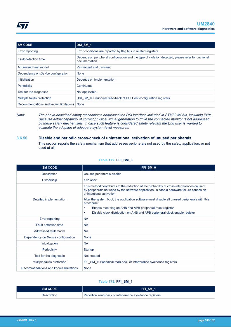
SM CODE DSI_SM_1
Error reporting Error conditions are reported by flag bits in related registers
Fault detection time Depends on peripheral configuration and the type of violation detected, please refer to functionaldocumentation
Addressed fault model Permanent and transient
Dependency on Device configuration None
Initialization Depends on implementation
Periodicity Continuous
Test for the diagnostic Not applicable
Multiple faults protection DSI_SM_0: Periodical read-back of DSI Host configuration registers
Recommendations and known limitations None
Note: The above-described safety mechanisms addresses the DSI interface included in STM32 MCUs, including PHY.Because actual capability of correct physical signal generation to drive the connected monitor is not addressedby these safety mechanisms, in case such feature is considered safety relevant the End user is warned toevaluate the adoption of adequate system-level measures.
3.6.50 Disable and periodic cross-check of unintentional activation of unused peripheralsThis section reports the safety mechanism that addresses peripherals not used by the safety application, or notused at all.
Table 172. FFI_SM_0
SM CODE FFI_SM_0
Description Unused peripherals disable
Ownership End user
Detailed implementation
This method contributes to the reduction of the probability of cross-interferences causedby peripherals not used by the software application, in case a hardware failure causes anunintentional activation.
After the system boot, the application software must disable all unused peripherals with thisprocedure:• Enable reset flag on AHB and APB peripheral reset register• Disable clock distribution on AHB and APB peripheral clock enable register
Error reporting NA
Fault detection time NA
Addressed fault model NA
Dependency on Device configuration None
Initialization NA
Periodicity Startup
Test for the diagnostic Not needed
Multiple faults protection FFI_SM_1: Periodical read-back of interference avoidance registers
Recommendations and known limitations None
Table 173. FFI_SM_1
SM CODE FFI_SM_1
Description Periodical read-back of interference avoidance registers
UM2840Hardware and software diagnostics
UM2840 - Rev 1 page 106/132

SM CODE FFI_SM_1
Ownership End user
Detailed implementation
This method contributes to the reduction of the probability of cross-interferences betweenperipherals that can potentially conflict on the same input/output pins, including for instanceunused peripherals. This diagnostic measure must be applied to following registers:• clock enable and disable registers• alternate function programming registers
Detailed information on the implementation of this method can be found inSection 3.6.7 EXTI controller.
Error reporting Refer to NVIC_SM_0
Fault detection time Refer to NVIC_SM_0
Addressed fault model Refer to NVIC_SM_0
Dependency on Device configuration Refer to NVIC_SM_0
Initialization Refer to NVIC_SM_0
Periodicity Refer to NVIC_SM_0
Test for the diagnostic Refer to NVIC_SM_0
Multiple faults protection Refer to NVIC_SM_0
Recommendations and known limitations Refer to NVIC_SM_0
UM2840Hardware and software diagnostics
UM2840 - Rev 1 page 107/132

3.6.51 System
Table 174. DUAL_SM_0
SM CODE DUAL_SM_0
Description Cross-check between two STM32 MCUs
Ownership End user
Detailed implementation
This method is implemented in the spirit of technique described in IEC 61508-7, A.3.5 “Reciprocal comparisonby software”, which is rated in IEC 61508-2 Table A.4 as capable to achieve high level of diagnostic coverage.
The two processing units exchange data reciprocally, and a fail in the comparison is considered as a detectionof a failure in one of the two unit. The guidelines for the implementation are the following:• Data exchanged include output results, intermediate results(1) and the results of each software-
implemented safety mechanisms executed on periodical basis on both MCUs (for exampleCPUM7_SM_0, CPUM4_SM_0)
• Software routines devoted to data exchange/comparison must be logically separated from the softwareimplementing the safety function(s).
• Systematic capability of data exchange/comparison software must be equal or above the one of thesoftware implementing the safety function(s).
• Independency and lack of interference between the software implementing the data exchange/comparison and the one implementing the safety function(s) must be proven.
• Frequency of data exchange/comparison is imposed by the system PST (refer to (1) related timingconstraints for “periodic” safety mechanisms), except for output results which needs to be exchanged/compared at the same rate they are potentially updated.
Fault detection time Depends on implementation
Addressed fault model Permanent and transient
Dependency on Deviceconfiguration None
Initialization Depends on implementation
Periodicity Periodic
Test for the diagnostic N/A
Multiple faults protection CPUM7_SM_0, CPUM4_SM_0: periodical core self-test software (individually executed on both processingunits)
Recommendations andknown limitations
This method is usually rated as “optional” because it is not strictly needed in the framework of 1oo2 architecturedescribed in Section 3.2.4 Reference safety architectures - 1oo2; anyway, it is included here only for its use insuch an architecture.
This method can provide additional safety margin for systems needing further protection against faultaccumulation.
Because this method could be a potential source of common cause failure between the two 1oo2 channels (incase of incorrect implementation), End user is recommended to carefully follow above the reported guidelines(box “Detailed Implementation”).
1. It is defined here “intermediate result” the value of each variable able to directly influence the final individualchannel output. To give some examples:- if final output is a value resulting from some computation (for example a PWM rate), “intermediate results”are the values of each variable included in such computation.- if final output if the result of a decision (for example GPIO value decided on the basis of the comparisonbetween values), “intermediate results” are the values of each variable involved in such decision.
3.7 Conditions of useThe table below provides a summary of the safety concept recommendations reported in Section 3.6 Hardwareand software diagnostics. The conditions of use to be applied to STM32H7 dual-core MCUs are reported in formof safety mechanism requirements. Exception is represented by some conditions of use introduced by FMEAanalysis in order to correctly address specific failure modes. These conditions of use are reported at the end ofthe table presented in this section.
UM2840Conditions of use
UM2840 - Rev 1 page 108/132
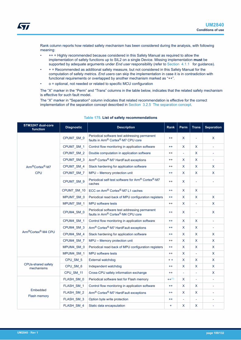
Rank column reports how related safety mechanism has been considered during the analysis, with followingmeaning:• ++ = Highly recommended because considered in this Safety Manual as required to allow the
implementation of safety functions up to SIL2 on a single Device. Missing implementation must besupported by adequate arguments under End user responsibility (refer to Section 4.1.1 for guidance).
• + = Recommended as additional safety measure, but not considered in this Safety Manual for thecomputation of safety metrics. End users can skip the implementation in case it is in contradiction withfunctional requirements or overlapped by another mechanism marked as “++”.
• o = optional, not needed or related to specific MCU configuration
The “X” marker in the “Perm” and “Trans” columns in the table below, indicates that the related safety mechanismis effective for such fault model.The “X” marker in "Separation" column indicates that related recommendation is effective for the correctimplementation of the separation concept described in Section 3.2.5 The separation concept.
Table 175. List of safety recommendations
STM32H7 dual-corefunction Diagnostic Description Rank Perm Trans Separation
Arm®Cortex®‑M7
CPU
CPUM7_SM_0Periodical software test addressing permanentfaults in Arm® Cortex®‑M7 CPU core
++ X - X
CPUM7_SM_1 Control flow monitoring in application software ++ X X -
CPUM7_SM_2 Double computation in application software ++ - X -
CPUM7_SM_3 Arm® Cortex®‑M7 HardFault exceptions ++ X X -
CPUM7_SM_4 Stack hardening for application software ++ X X X
CPUM7_SM_7 MPU – Memory protection unit ++ X X X
CPUM7_SM_9 Periodical self‑test software for Arm® Cortex®-M7caches
++ X - -
CPUM7_SM_10 ECC on Arm® Cortex®‑M7 L1 caches ++ X X
MPUM7_SM_0 Periodical read‑back of MPU configuration registers ++ X X X
MPUM7_SM_1 MPU software tests ++ X - X
Arm®Cortex®‑M4 CPU
CPUM4_SM_0Periodical software test addressing permanentfaults in Arm® Cortex®‑M4 CPU core
++ X - X
CPUM4_SM_1 Control flow monitoring in application software ++ X X -
CPUM4_SM_3 Arm® Cortex®‑M7 HardFault exceptions ++ X X -
CPUM4_SM_4 Stack hardening for application software ++ X X X
CPUM4_SM_7 MPU – Memory protection unit ++ X X X
MPUM4_SM_0 Periodical read‑back of MPU configuration registers ++ X X X
MPUM4_SM_1 MPU software tests ++ X - X
CPUs-shared safetymechanisms
CPU_SM_5 External watchdog + + X X X
CPU_SM_6 Independent watchdog ++ X X X
CPU_SM_11 Cross-CPU safety information exchange ++ - - X
Embedded
Flash memory
FLASH_SM_0 Periodical software test for Flash memory ++(1) X - -
FLASH_SM_1 Control flow monitoring in application software ++ X X -
FLASH_SM_2 Arm® Cortex®‑M7 HardFault exceptions ++ X X -
FLASH_SM_3 Option byte write protection ++ - - -
FLASH_SM_4 Static data encapsulation + X X -
UM2840Conditions of use
UM2840 - Rev 1 page 109/132

STM32H7 dual-corefunction Diagnostic Description Rank Perm Trans Separation
Embedded
Flash memory
FLASH_SM_6 Flash unused area filling code + - - -
FLASH_SM_7 ECC on Flash memory ++ X X -
FLASH_SM_8 Read/Write/Proprietary code protection + - - -
FLASH_SM_9 Periodic test by software for Flash memory addressdecoder ++ X - -
Embedded SRAM
RAM_SM_0 Periodical software test for SRAM + X - -
RAM_SM_2 Stack hardening for application software + X X -
RAM_SM_3 Information redundancy for system variables inapplication software ++ X X -
RAM_SM_4 Control flow monitoring in application software o (2) X X -
RAM_SM_5 Periodical integrity test for application software inRAM o(2) X X -
RAM_SM_6 Read protection (RDP), Write protection (WRP) + - - -
RAM_SM_7 ECC on SRAM ++ X X -
RAM_SM_8 Periodic test by software for SRAM addressdecoder ++ X - -
System architectureBUS_SM_0 Periodical software test for interconnections ++ X - -
BUS_SM_1 Information redundancy in intra‑chip dataexchanges ++ X X -
EXTI controllerNVIC_SM_0 Periodical read‑back of configuration registers ++ X X -
NVIC_SM_1 Expected and unexpected interrupt check byapplication software ++ X X -
DMA, MDMA, BDMA,DMAMUX
DMA_SM_0 Periodical read‑back of configuration registers ++ X X -
DMA_SM_1 Information redundancy on data packet transferredvia DMA ++ X X -
DMA_SM_2Information redundancy by including sender orreceiver identifier on data packet transferred viaDMA
++ X X -
DMA_SM_3 Periodical software test for DMA ++ X - -
DMA_SM_4 DMA transaction awareness ++ X X -
DMA2D
DMA2D_SM_0 Periodical read‑back of DMA2D configurationregisters ++ X X -
DMA2D_SM_1 Periodical software test for DMA2D functions ++ X - -
DMA2D_SM_2 DMA processing and interrupt awareness ++ X X -
HSEMHSEM_SM_0 Periodical read‑back of HSEM configuration
registers ++ X X -
HSEM_SM_1 Control flow monitoring for concurrent tasks ++ X X -
Single Wire ProtocolMaster Interface
SWPMI_SM_0 Periodical read‑back of SWPMI configurationregisters ++ X X -
SWPMI_SM_1 Protocol error signals and information redundancyincluding hardware CRC ++ X X -
SWPMI_SM_2 SWMPI loopback test + X - -
SWPMI_SM_3 Information redundancy techniques on messagesto implement full end-to-end operation ++ X X -
FDCANCAN_SM_0 Periodical read‑back of configuration registers ++ X X -
CAN_SM_1 Protocol error signals ++ X X -
UM2840Conditions of use
UM2840 - Rev 1 page 110/132
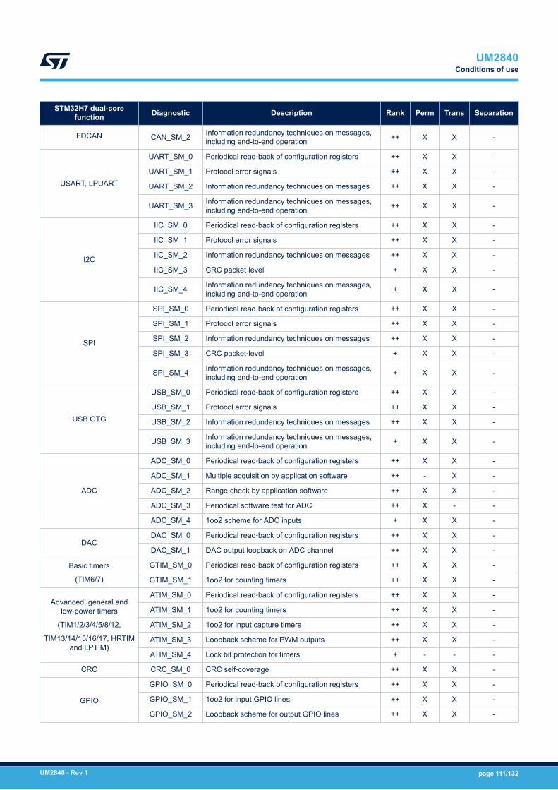
STM32H7 dual-corefunction Diagnostic Description Rank Perm Trans Separation
FDCAN CAN_SM_2 Information redundancy techniques on messages,including end-to-end operation ++ X X -
USART, LPUART
UART_SM_0 Periodical read‑back of configuration registers ++ X X -
UART_SM_1 Protocol error signals ++ X X -
UART_SM_2 Information redundancy techniques on messages ++ X X -
UART_SM_3 Information redundancy techniques on messages,including end-to-end operation ++ X X -
I2C
IIC_SM_0 Periodical read‑back of configuration registers ++ X X -
IIC_SM_1 Protocol error signals ++ X X -
IIC_SM_2 Information redundancy techniques on messages ++ X X -
IIC_SM_3 CRC packet‑level + X X -
IIC_SM_4 Information redundancy techniques on messages,including end-to-end operation + X X -
SPI
SPI_SM_0 Periodical read‑back of configuration registers ++ X X -
SPI_SM_1 Protocol error signals ++ X X -
SPI_SM_2 Information redundancy techniques on messages ++ X X -
SPI_SM_3 CRC packet‑level + X X -
SPI_SM_4 Information redundancy techniques on messages,including end-to-end operation + X X -
USB OTG
USB_SM_0 Periodical read‑back of configuration registers ++ X X -
USB_SM_1 Protocol error signals ++ X X -
USB_SM_2 Information redundancy techniques on messages ++ X X -
USB_SM_3 Information redundancy techniques on messages,including end-to-end operation + X X -
ADC
ADC_SM_0 Periodical read‑back of configuration registers ++ X X -
ADC_SM_1 Multiple acquisition by application software ++ - X -
ADC_SM_2 Range check by application software ++ X X -
ADC_SM_3 Periodical software test for ADC ++ X - -
ADC_SM_4 1oo2 scheme for ADC inputs + X X -
DACDAC_SM_0 Periodical read‑back of configuration registers ++ X X -
DAC_SM_1 DAC output loopback on ADC channel ++ X X -
Basic timers
(TIM6/7)
GTIM_SM_0 Periodical read‑back of configuration registers ++ X X -
GTIM_SM_1 1oo2 for counting timers ++ X X -
Advanced, general andlow‑power timers
(TIM1/2/3/4/5/8/12,
TIM13/14/15/16/17, HRTIMand LPTIM)
ATIM_SM_0 Periodical read‑back of configuration registers ++ X X -
ATIM_SM_1 1oo2 for counting timers ++ X X -
ATIM_SM_2 1oo2 for input capture timers ++ X X -
ATIM_SM_3 Loopback scheme for PWM outputs ++ X X -
ATIM_SM_4 Lock bit protection for timers + - - -
CRC CRC_SM_0 CRC self‑coverage ++ X X -
GPIO
GPIO_SM_0 Periodical read‑back of configuration registers ++ X X -
GPIO_SM_1 1oo2 for input GPIO lines ++ X X -
GPIO_SM_2 Loopback scheme for output GPIO lines ++ X X -
UM2840Conditions of use
UM2840 - Rev 1 page 111/132
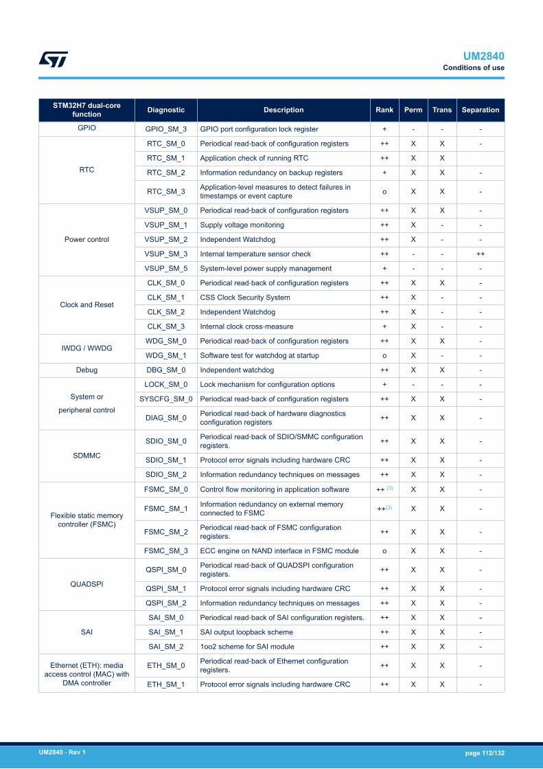
STM32H7 dual-corefunction Diagnostic Description Rank Perm Trans Separation
GPIO GPIO_SM_3 GPIO port configuration lock register + - - -
RTC
RTC_SM_0 Periodical read‑back of configuration registers ++ X X -
RTC_SM_1 Application check of running RTC ++ X X
RTC_SM_2 Information redundancy on backup registers + X X -
RTC_SM_3 Application‑level measures to detect failures intimestamps or event capture o X X -
Power control
VSUP_SM_0 Periodical read‑back of configuration registers ++ X X -
VSUP_SM_1 Supply voltage monitoring ++ X - -
VSUP_SM_2 Independent Watchdog ++ X - -
VSUP_SM_3 Internal temperature sensor check ++ - - ++
VSUP_SM_5 System-level power supply management + - - -
Clock and Reset
CLK_SM_0 Periodical read‑back of configuration registers ++ X X -
CLK_SM_1 CSS Clock Security System ++ X - -
CLK_SM_2 Independent Watchdog ++ X - -
CLK_SM_3 Internal clock cross‑measure + X - -
IWDG / WWDGWDG_SM_0 Periodical read‑back of configuration registers ++ X X -
WDG_SM_1 Software test for watchdog at startup o X - -
Debug DBG_SM_0 Independent watchdog ++ X X -
System or
peripheral control
LOCK_SM_0 Lock mechanism for configuration options + - - -
SYSCFG_SM_0 Periodical read‑back of configuration registers ++ X X -
DIAG_SM_0 Periodical read‑back of hardware diagnosticsconfiguration registers ++ X X -
SDMMC
SDIO_SM_0 Periodical read‑back of SDIO/SMMC configurationregisters. ++ X X -
SDIO_SM_1 Protocol error signals including hardware CRC ++ X X -
SDIO_SM_2 Information redundancy techniques on messages ++ X X -
Flexible static memorycontroller (FSMC)
FSMC_SM_0 Control flow monitoring in application software ++ (3) X X -
FSMC_SM_1 Information redundancy on external memoryconnected to FSMC ++(3) X X -
FSMC_SM_2 Periodical read‑back of FSMC configurationregisters. ++ X X -
FSMC_SM_3 ECC engine on NAND interface in FSMC module o X X -
QUADSPI
QSPI_SM_0 Periodical read‑back of QUADSPI configurationregisters. ++ X X -
QSPI_SM_1 Protocol error signals including hardware CRC ++ X X -
QSPI_SM_2 Information redundancy techniques on messages ++ X X -
SAI
SAI_SM_0 Periodical read‑back of SAI configuration registers. ++ X X -
SAI_SM_1 SAI output loopback scheme ++ X X -
SAI_SM_2 1oo2 scheme for SAI module ++ X X -
Ethernet (ETH): mediaaccess control (MAC) with
DMA controller
ETH_SM_0 Periodical read‑back of Ethernet configurationregisters. ++ X X -
ETH_SM_1 Protocol error signals including hardware CRC ++ X X -
UM2840Conditions of use
UM2840 - Rev 1 page 112/132
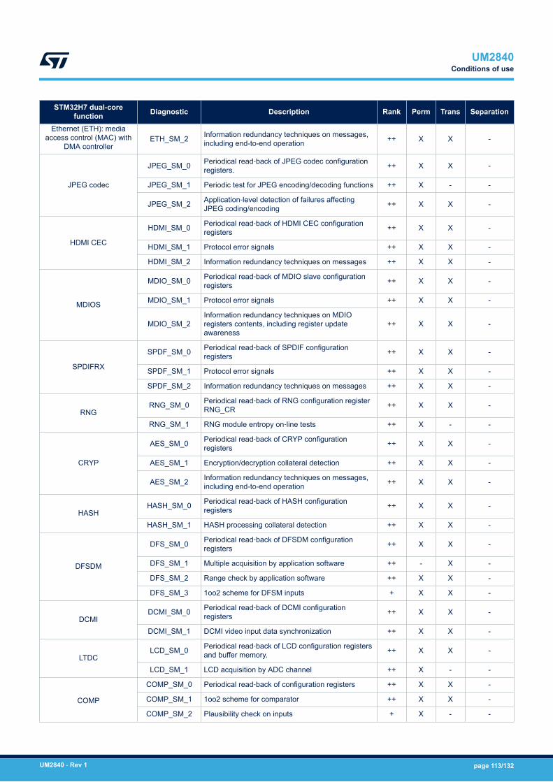
STM32H7 dual-corefunction Diagnostic Description Rank Perm Trans Separation
Ethernet (ETH): mediaaccess control (MAC) with
DMA controllerETH_SM_2 Information redundancy techniques on messages,
including end-to-end operation ++ X X -
JPEG codec
JPEG_SM_0 Periodical read‑back of JPEG codec configurationregisters. ++ X X -
JPEG_SM_1 Periodic test for JPEG encoding/decoding functions ++ X - -
JPEG_SM_2 Application‑level detection of failures affectingJPEG coding/encoding ++ X X -
HDMI CEC
HDMI_SM_0 Periodical read‑back of HDMI CEC configurationregisters ++ X X -
HDMI_SM_1 Protocol error signals ++ X X -
HDMI_SM_2 Information redundancy techniques on messages ++ X X -
MDIOS
MDIO_SM_0 Periodical read‑back of MDIO slave configurationregisters ++ X X -
MDIO_SM_1 Protocol error signals ++ X X -
MDIO_SM_2Information redundancy techniques on MDIOregisters contents, including register updateawareness
++ X X -
SPDIFRX
SPDF_SM_0 Periodical read‑back of SPDIF configurationregisters ++ X X -
SPDF_SM_1 Protocol error signals ++ X X -
SPDF_SM_2 Information redundancy techniques on messages ++ X X -
RNGRNG_SM_0 Periodical read‑back of RNG configuration register
RNG_CR ++ X X -
RNG_SM_1 RNG module entropy on‑line tests ++ X - -
CRYP
AES_SM_0 Periodical read‑back of CRYP configurationregisters ++ X X -
AES_SM_1 Encryption/decryption collateral detection ++ X X -
AES_SM_2 Information redundancy techniques on messages,including end-to-end operation ++ X X -
HASHHASH_SM_0 Periodical read‑back of HASH configuration
registers ++ X X -
HASH_SM_1 HASH processing collateral detection ++ X X -
DFSDM
DFS_SM_0 Periodical read‑back of DFSDM configurationregisters ++ X X -
DFS_SM_1 Multiple acquisition by application software ++ - X -
DFS_SM_2 Range check by application software ++ X X -
DFS_SM_3 1oo2 scheme for DFSM inputs + X X -
DCMIDCMI_SM_0 Periodical read‑back of DCMI configuration
registers ++ X X -
DCMI_SM_1 DCMI video input data synchronization ++ X X -
LTDCLCD_SM_0 Periodical read‑back of LCD configuration registers
and buffer memory. ++ X X -
LCD_SM_1 LCD acquisition by ADC channel ++ X - -
COMP
COMP_SM_0 Periodical read‑back of configuration registers ++ X X -
COMP_SM_1 1oo2 scheme for comparator ++ X X -
COMP_SM_2 Plausibility check on inputs + X - -
UM2840Conditions of use
UM2840 - Rev 1 page 113/132

STM32H7 dual-corefunction Diagnostic Description Rank Perm Trans Separation
COMPCOMP_SM_3 Multiple acquisition by application software + - X -
COMP_SM_4 Comparator LOCK mechanism + - - -
OPAMP AMP_SM_0 Periodical read‑back of OPAMP configurationregisters ++ X X -
DLYB DLB_SM_0 Periodical read‑back of DLYB configurationregisters ++ X X -
VREFBUFVREF_SM_0 Periodical read-back of VREFBUF system
configuration registers ++ X X -
VREF_SM_1 VREF cross-check by ADC reading + X - -
DSIDSI_SM_0 Periodical read-back of DSI Host configuration
registers ++ X X -
DSI_SM_1 Protocol error signals and information redundancyincluding hardware checksums ++ X X -
Part separation
(no interference)
FFI_SM_0 Unused peripherals disable ++ - - -
FFI_SM_1 Periodical read‑back of interference avoidanceregisters ++ - - X
Arm® Cortex®‑M7 and M4
CPUCoU_1
The reset condition of Arm® Cortex®‑M7 and M4CPUs must be compatible as valid safe state atsystem level
++ - - -
Debug CoU_2 STM32H7 Series debug features must not be usedin safety function(s) implementation ++ - - -
Arm® Cortex®‑M7, M4 /Supply system
CoU_3 Low power mode state must not be used in safetyfunction(s) implementation ++ - - -
STM32H7 Seriesperipherals CoU_4
End user must implement the requiredcombination of safety mechanism/CoUs for eachSTM32 peripherals used in safety function(s)implementation
++ X X -
Flash subsystem CoU_5During Flash memory bank mass erase andreprogramming there must not be safety function(s)executed by STM32H7 MCU.
++ - - -
Flash subsystem CoU_6
On‑field application software live update bydual‑Flash system must include the executionof code/data integrity check by methods likeFLASH_SM_0
++ X X -
CPUs subsystems CoU_7In case of multiple safety functionsimplementations, methods to guarantee theirmutual independence must include MPU use.
++ - - -
CRS CoU_8 CRS features must not be used in safetyfunction(s) implementation ++ - - -
Device CoU_9
For each implemented safety mechanisms, relatederror/fault detection signal(s)/message(s) must beprocessed by the application software for thecorrect management of SS1 safe state. Relatedsoftware routines must be considered as safetyrelated in the framework of the overall policy forsoftware systematic capability in the final system.(4)
++ - - -
Embedded SRAM CoU_10
RAM space used by each Device CPU for safetyfunction(5) implementation (including stacks space)must be kept separated, except the area specifiedby CoU_11. Allocation must be static.
++ - - X
UM2840Conditions of use
UM2840 - Rev 1 page 114/132

STM32H7 dual-corefunction Diagnostic Description Rank Perm Trans Separation
Embedded SRAM
CoU_11Data exchanges between the two CPUs of theDevice must use a dedicated shared memoryspace defined in SRAM.
++ - - X
CoU_12Memory Protection Units (MPU) of each DeviceCPU must be used to enforce the implementationof CoU_10, CoU_11.
++ - - X
Watchdogs
CoU_13The external watchdog must supervise the correctbehavior of both Device CPUs. Communicationschemes are ruled by CoU_14
++ X X X
CoU_14
CPUs communications with the external watchdogmust be managed either:1. Both CPUs can communicate with the
external watchdog. In this case the watchdogmust be able to identify which CPU issending the message, or
2. Only one CPU drives the external watchdogand acts as supervisor for the other CPU.In this case the first CPU must be able torequest a reset in case the second CPU isunresponsive or reporting a failure detection.
++ - - X
CoU_15In the Device, each of the two internal watchdogsIWDG and WWDG must be statically allocated toonly one CPU(6).
++ - - X
CoU_16
External and internal watchdog managementsoftware routines (implementing requirements ofCoU_13,14,15) must be developed with softwaresystematic capability (SC) not lower than thehighest available on the system, and in any caseat least equal to SC2
++ - - X
Part separation
(no interference)CoU_17
During system boot, a combination of theexternal watchdog and system-level measuresmust guarantee the overall safe state in case ofmissed correct application software start on eachCPU. Exit from this power-up safe state must belinked also to the successful execution (beforethe application software start) of following safetymeasures:
CPUM7_SM_0
MPUM7_SM_0
MPUM7_SM_1
CPUM4_SM_0
MPUM4_SM_0
MPUM4_SM_1
FLASH_SM_0
++ - - X
1oo2 architecture CoU_18
In 1oo2 architecture the PEv must keep the finalsystem in safe state after the power-up until bothSTM32H7 performed their exit from the power-upsafe state ruled by CoU_17
++ - - X
Device DUAL_SM_0 Cross-check between two STM32 MCUs o X X -
1. Ranked "++" because considered as mitigation measure for Multiple-fault protection for FLASH_SM_7 (referto related description).
2. Must be considered ranked as “++” if the application software is executed on RAM.3. Can be considered ranked as “o” depending on the intended use of external memory connected to FSMC.4. To provide an example, safety recommendation "CPUM7_SM_3 Arm® Cortex®‑M7 HardFault exceptions"
cannot be considered correctly satisfied if related exception handler is not implemented in software.
UM2840Conditions of use
UM2840 - Rev 1 page 115/132
5. It is reminded that any software-based safety mechanisms like CPUM7_SM_0, CPUM4_SM_0 must beconsidered “safety functions” and so they must comply to this CoU.
6. Therefore, trigger action on each internal watchdog must be possible for only one CPU, statically selected atsoftware design time.
The above-described safety mechanism or conditions of use are conceived with different levels of abstractiondepending on their nature: the more a safety mechanism is implemented as application-independent, the wider isits possible use on a large range of End user applications.The safety analysis highlights two major partitions inside the MCU:• System-critical MCU modules. Every End user application is affected from a safety point of view by
a failure on these modules. Because these modules are used by every End user application, relatedmethods or safety mechanism are mainly conceived to be application-independent. For STM32H7 dual-core microcontroller system critical modules are: the two CPUs, Reset, Power, Clocks, Busmatrixs andInterconnect, Flash and RAM memories (including their interfaces)
• Peripheral modules. Such modules could be not used by the End user application, or they could be used fornon-safety related tasks. Related safety methods are therefore implemented mainly at application level, asapplication software solutions or architectural solutions.
UM2840Conditions of use
UM2840 - Rev 1 page 116/132
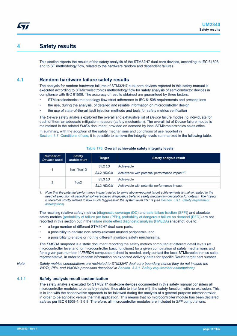
4 Safety results
This section reports the results of the safety analysis of the STM32H7 dual-core devices, according to IEC 61508and to ST methodology flow, related to the hardware random and dependent failures.
4.1 Random hardware failure safety resultsThe analysis for random hardware failures of STM32H7 dual-core devices reported in this safety manual isexecuted according to STMicroelectronics methodology flow for safety analysis of semiconductor devices incompliance with IEC 61508. The accuracy of results obtained are guaranteed by three factors:• STMicroelectronics methodology flow strict adherence to IEC 61508 requirements and prescriptions• the use, during the analysis, of detailed and reliable information on microcontroller design• the use of state-of-the-art fault injection methods and tools for safety metrics verification
The Device safety analysis explored the overall and exhaustive list of Device failure modes, to individuate foreach of them an adequate mitigation measure (safety mechanism). The overall list of Device failure modes ismaintained in the related FMEA document, provided on demand by local STMicroelectronics sales office.In summary, with the adoption of the safety mechanisms and conditions of use reported inSection 3.7 Conditions of use, it is possible to achieve the integrity levels summarized in the following table.
Table 176. Overall achievable safety integrity levels
Number ofDevices used
Safetyarchitecture Target Safety analysis result
1 1oo1/1oo1DSIL2 LD Achievable
SIL2 HD/CM Achievable with potential performance impact (1)
2 1oo2SIL3 LD Achievable
SIL3 HD/CM Achievable with potential performance impact
1. Note that the potential performance impact related to some above-reported target achievements is mainly related to theneed of execution of periodical software-based diagnostics (refer to safety mechanism description for details). The impactis therefore strictly related to how much “aggressive” the system level PST is (see Section 3.3.1 Safety requirementassumptions).
The resulting relative safety metrics (diagnostic coverage (DC) and safe failure fraction (SFF)) and absolutesafety metrics (probability of failure per hour (PFH), probability of dangerous failure on demand (PFD)) are notreported in this section but in the failure mode effect diagnostic analysis (FMEDA) snapshot, due to:• a large number of different STM32H7 dual-core parts,• a possibility to declare non-safety-relevant unused peripherals, and• a possibility to enable or not the different available safety mechanisms.
The FMEDA snapshot is a static document reporting the safety metrics computed at different detail levels (atmicrocontroller level and for microcontroller basic functions) for a given combination of safety mechanisms andfor a given part number. If FMEDA computation sheet is needed, early contact the local STMicroelectronics salesrepresentative, in order to receive information on expected delivery dates for specific Device target part number.
Note: Safety metrics computations are restricted to STM32H7 dual-core boundary, hence they do not include theWDTe, PEv, and VMONe processes described in Section 3.3.1 Safety requirement assumptions).
4.1.1 Safety analysis result customizationThe safety analysis executed for STM32H7 dual-core devices documented in this safety manual considers allmicrocontroller modules to be safety-related, thus able to interfere with the safety function, with no exclusion. Thisis in line with the conservative approach to be followed during the analysis of a general-purpose microcontroller,in order to be agnostic versus the final application. This means that no microcontroller module has been declaredsafe as per IEC 61508-4, 3.6.8. Therefore, all microcontroller modules are included in SFF computations.
UM2840Safety results
UM2840 - Rev 1 page 117/132
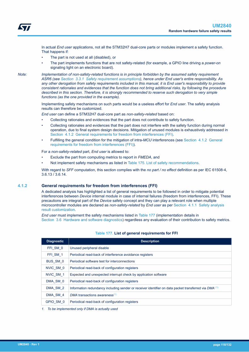
In actual End user applications, not all the STM32H7 dual-core parts or modules implement a safety function.That happens if:• The part is not used at all (disabled), or• The part implements functions that are not safety-related (for example, a GPIO line driving a power-on
signaling light on an electronic board).
Note: Implementation of non-safety-related functions is in principle forbidden by the assumed safety requirementASR6 (see Section 3.3.1 Safety requirement assumptions), hence under End user's entire responsibility. Asany other derogation from safety requirements included in this manual, it is End user's responsibility to provideconsistent rationales and evidences that the function does not bring additional risks, by following the proceduredescribed in this section. Therefore, it is strongly recommended to reserve such derogation to very simplefunctions (as the one provided in the example).
Implementing safety mechanisms on such parts would be a useless effort for End user. The safety analysisresults can therefore be customized.End user can define a STM32H7 dual-core part as non-safety-related based on:• Collecting rationales and evidences that the part does not contribute to safety function.• Collecting rationales and evidences that the part does not interfere with the safety function during normal
operation, due to final system design decisions. Mitigation of unused modules is exhaustively addressed inSection 4.1.2 General requirements for freedom from interferences (FFI).
• Fulfilling the general condition for the mitigation of intra-MCU interferences (see Section 4.1.2 Generalrequirements for freedom from interferences (FFI)).
For a non-safety-related part, End user is allowed to:• Exclude the part from computing metrics to report in FMEDA, and• Not implement safety mechanisms as listed in Table 175. List of safety recommendations.
With regard to SFF computation, this section complies with the no part / no effect definition as per IEC 61508‑4,3.6.13 / 3.6.14.
4.1.2 General requirements for freedom from interferences (FFI)A dedicated analysis has highlighted a list of general requirements to be followed in order to mitigate potentialinterferences between Device internal module in case of internal failures (freedom from interferences, FFI). Theseprecautions are integral part of the Device safety concept and they can play a relevant role when multiplemicrocontroller modules are declared as non-safety-related by End user as per Section 4.1.1 Safety analysisresult customization.End user must implement the safety mechanisms listed in Table 177 (implementation details inSection 3.6 Hardware and software diagnostics) regardless any evaluation of their contribution to safety metrics.
Table 177. List of general requirements for FFI
Diagnostic Description
FFI_SM_0 Unused peripheral disable
FFI_SM_1 Periodical read-back of interference avoidance registers
BUS_SM_0 Periodical software test for interconnections
NVIC_SM_0 Periodical read-back of configuration registers
NVIC_SM_1 Expected and unexpected interrupt check by application software
DMA_SM_0 Periodical read-back of configuration registers
DMA_SM_2 Information redundancy including sender or receiver identifier on data packet transferred via DMA (1)
DMA_SM_4 DMA transactions awareness(1)
GPIO_SM_0 Periodical read-back of configuration registers
1. To be implemented only if DMA is actually used
UM2840Random hardware failure safety results
UM2840 - Rev 1 page 118/132

4.1.3 Notes on multiple-fault scenarioAccording to the requirements of IEC61508, the safety analysis for STM32H7 dual-core devices consideredmultiple-fault scenarios. Furthermore, following the spirit of ISO26262 (the reference and state-of-the-art standardnorm for integrated circuit safety analysis), the analysis investigated possible causes preventing the implementedsafety mechanisms from being effective, in order to determine appropriate counter-measures. In the Multiple-faultprotection field, the tables in Section 3.6 Hardware and software diagnostics report the safety mechanismsrequired to properly manage a multiple-fault scenario, including mitigation measures against failures makingsafety mechanisms ineffective. It is strongly recommended that the safety concept includes such mitigationmeasures, and in particular for systems operating during long periods, as they tend to accumulate errors. Indeed,fault accumulation issue has been taken into account during STM32H7 dual-core devices safety analysis.Another potential source of multiple error condition is the accumulation of permanent failures during power-offperiods. Indeed, if the end system is not powered, no safety mechanism are active and so able to early detectthe insurgence of such failures. To mitigate this potential issue, it is strongly recommended to execute all periodicsafety mechanism at each system power-up; this measure guarantees a fresh system start with a fault-freehardware. This recommendation is given for periodic safety mechanisms rated as "++" (highly recommended) inthe Device safety concept, and mainly for the most relevant ones in term of failure distribution: CPUM7_SM_0,CPUM4_SM_0, FLASH_SM_0, RAM_SM_0. This startup execution is strongly recommended regardless thesafety functions mode of operations and/or the value of PST.
4.2 Analysis of dependent failuresThe analysis of dependent failures is important for microcontroller and microprocessor devices. The mainsubclasses of dependent failures are CCFs. Their analysis is ruled by IEC 61508-2 annex E, which lists thedesign requirements to be verified to allow the use of on-chip redundancy for integrated circuits with one commonsemiconductor substrate.As there is no on-chip redundancy on STM32H7 dual-core devices, the CCF quantification through the βICcomputation method - as required by Annex E.1, item i - is not required. Note that, in the case of 1oo2safety architecture implementation, End user is required to evaluate the β and βD parameters (used in PFHcomputation) that reflect the common cause factors between the two channels.The Device architecture and structures can be potential sources of dependent failures. These are analyzed inthe following sections. The referred safety mechanisms are described in Section 3.6 Hardware and softwarediagnostics.
4.2.1 Power supplyPower supply is a potential source of dependent failures, because any alteration can simultaneously affectmany modules, leading to not-independent failures. The following safety mechanisms address and mitigate thosedependent failures:• VSUP_SM_1: detection of abnormal value of supply voltage;• VSUP_SM_2: the external watchdog is different from the digital core of the MCU, and this diversity helps to
mitigate dependent failures related to the main supply alterations. As reported in VSUP_SM_2 description,separate power supply for IWDG or/and the adoption of an external watchdog (CPU_SM_5) increase suchdiversity.
The adoption of such safety mechanisms is therefore highly recommended despite their minor contribution to thesafety metrics to reach the required safety integrity level. Refer to Section 3.6.23 Power controller (PWR) for thedetailed safety mechanism descriptions.
4.2.2 ClockSystem clocks are a potential source of dependent failures, because alterations in the clock characteristics(frequency, jitter) can affect many parts, leading to not-independent failures. The following safety mechanismsaddress and mitigate such dependent failures:• CLK_SM_1: the clock security system is able to detect hard alterations (stop) of system clock and activate
the adequate recovery actions.• CLK_SM_2: the external watchdog has a dedicated clock source. The frequency alteration of the system
clock leads to the watchdog window violations by the triggering routine on Application software, leading tothe MCU reset by watchdog.
UM2840Analysis of dependent failures
UM2840 - Rev 1 page 119/132

The adoption of such safety mechanism is therefore highly recommended despite their minor contribution to thesafety metrics to reach the required safety integrity level. Refer to Section 3.6.24 Reset and clock controller(RCC) for detailed safety mechanisms description.
4.2.3 DMAThe DMA function can be involved in data transfers operated by most of the peripherals. Failures of DMA caninterfere with the behavior of the system peripherals or Application software, leading to dependent failures. Theadoption of the following safety mechanisms is therefore highly recommended (refer to Section 3.6.8 Directmemory access controllers (DMA, MDMA, BDMA and DMA request multiplexer (DMAMUX)) for description):• DMA_SM_0• DMA_SM_1• DMA_SM_2
Note: Only DMA_SM_0 must be implemented if DMA is not used for data transfer.
4.2.4 Internal temperatureThe abnormal increase of the internal temperature is a potential source of dependent failures, as it can affectmany MCU parts. The following safety mechanism mitigates this potential effect (refer to Section 3.6.23 Powercontroller (PWR) for description):VSUP_SM_3: the internal temperature read and check allows the user to quickly detect potential risky conditionsbefore they lead to a series of internal failures.
UM2840Analysis of dependent failures
UM2840 - Rev 1 page 120/132
5 List of evidences
A safety case database stores all the information related to the safety analysis performed to derive the results andconclusions reported in this safety manual.The safety case database is composed of the following:• safety case with the full list of all safety-analysis-related documents• STMicroelectronics' internal FMEDA tool database for the computation of safety metrics, including estimated
and measured values• safety report, a document that describes in detail the safety analysis executed on STM32H7 dual-core
devices and the clause-by-clause compliance to IEC 61508• STMicroelectronics' internal fault injection campaign database including tool configuration and settings, fault
injection logs and results
As these materials contain STMicroelectronics' confidential information, they are only available for the purpose ofaudit and inspection by authorized bodies, without being published, which conforms to Note 2 of IEC 61508-2,7.4.9.7.
UM2840List of evidences
UM2840 - Rev 1 page 121/132
Revision history
Table 178. Document revision history
Date Version Changes
05-Jul-2021 1 Initial release.
UM2840
UM2840 - Rev 1 page 122/132

Glossary Application software within the software executed byDevice, the part that ensures functionality of End user'sapplication and integrates safety functions
CCF common cause failure
CM continuous mode
Compliant item any item subject to claim with respectto the clauses of IEC 61508 series of standards
COTS commercial off-the-shelf
CoU conditions of use
CPU central processing unit
CRC cyclic redundancy check
DC diagnostic coverage
Device depending on context, any single or all of theSTM32H7 dual-core silicon products
DMA direct memory access
DTI diagnostic test interval
ECM engine control module
ECU electronic control unit
End user individual person or company whointegrates Device in their application, such as anelectronic control board
EUC equipment under control
FIT failure in time
FMEA failure mode effect analysis
FMEDA failure mode effect diagnostic analysis
HD high-demand
HFT hardware fault tolerance
HW hardware
ITRS international technology roadmap forsemiconductors
LD low-demand
MCU microcontroller unit
MPU memory protection unit
MTBF mean time between failures
MTTFd mean time to dangerous failure
PDS(SR) safety-related power drive system
PEc programmable electronics - core
PEd programmable electronics - diagnostic
PFD probability of dangerous failure on demand
PFH probability of failure per hour
PL performance level
PST process safety time
SFF safe failure fraction
SIL safety integrity level
SILCL safety integrity level claim limit
SRCF safety-related control function
SRECS safety-related electrical control systems
SRP/CS safety-related parts of machinery controlsystems
UM2840Glossary
UM2840 - Rev 1 page 123/132
Contents
1 About this document . . . . . . . . . . . . . . . . . . . . . . . . . . . . . . . . . . . . . . . . . . . . . . . . . . . . . . . . . . . . . .2
1.1 Purpose and scope . . . . . . . . . . . . . . . . . . . . . . . . . . . . . . . . . . . . . . . . . . . . . . . . . . . . . . . . . . . . . 2
1.2 Normative references . . . . . . . . . . . . . . . . . . . . . . . . . . . . . . . . . . . . . . . . . . . . . . . . . . . . . . . . . . . 2
1.3 Reference documents. . . . . . . . . . . . . . . . . . . . . . . . . . . . . . . . . . . . . . . . . . . . . . . . . . . . . . . . . . . 3
2 Device development process . . . . . . . . . . . . . . . . . . . . . . . . . . . . . . . . . . . . . . . . . . . . . . . . . . . . . .4
3 Reference safety architecture . . . . . . . . . . . . . . . . . . . . . . . . . . . . . . . . . . . . . . . . . . . . . . . . . . . . . .5
3.1 Safety architecture introduction . . . . . . . . . . . . . . . . . . . . . . . . . . . . . . . . . . . . . . . . . . . . . . . . . . . 5
3.2 Compliant item. . . . . . . . . . . . . . . . . . . . . . . . . . . . . . . . . . . . . . . . . . . . . . . . . . . . . . . . . . . . . . . . . 5
3.2.1 Definition of Compliant item . . . . . . . . . . . . . . . . . . . . . . . . . . . . . . . . . . . . . . . . . . . . . . . . 5
3.2.2 Safety functions performed by Compliant item . . . . . . . . . . . . . . . . . . . . . . . . . . . . . . . . . . 6
3.2.3 Reference safety architectures - 1oo1. . . . . . . . . . . . . . . . . . . . . . . . . . . . . . . . . . . . . . . . . 8
3.2.4 Reference safety architectures - 1oo2. . . . . . . . . . . . . . . . . . . . . . . . . . . . . . . . . . . . . . . . . 9
3.2.5 The separation concept. . . . . . . . . . . . . . . . . . . . . . . . . . . . . . . . . . . . . . . . . . . . . . . . . . . 10
3.3 Safety analysis assumptions . . . . . . . . . . . . . . . . . . . . . . . . . . . . . . . . . . . . . . . . . . . . . . . . . . . . 11
3.3.1 Safety requirement assumptions . . . . . . . . . . . . . . . . . . . . . . . . . . . . . . . . . . . . . . . . . . . . 11
3.4 Electrical specifications and environment limits . . . . . . . . . . . . . . . . . . . . . . . . . . . . . . . . . . . . 13
3.5 Systematic safety integrity . . . . . . . . . . . . . . . . . . . . . . . . . . . . . . . . . . . . . . . . . . . . . . . . . . . . . . 13
3.6 Hardware and software diagnostics . . . . . . . . . . . . . . . . . . . . . . . . . . . . . . . . . . . . . . . . . . . . . . 14
3.6.1 Arm® Cortex®-M7 CPU . . . . . . . . . . . . . . . . . . . . . . . . . . . . . . . . . . . . . . . . . . . . . . . . . . . 15
3.6.2 Arm® Cortex®-M4 CPU . . . . . . . . . . . . . . . . . . . . . . . . . . . . . . . . . . . . . . . . . . . . . . . . . . 22
3.6.3 CPUs-shared safety mechanisms . . . . . . . . . . . . . . . . . . . . . . . . . . . . . . . . . . . . . . . . . . . 27
3.6.4 Embedded Flash memory . . . . . . . . . . . . . . . . . . . . . . . . . . . . . . . . . . . . . . . . . . . . . . . . . 29
3.6.5 Embedded SRAM . . . . . . . . . . . . . . . . . . . . . . . . . . . . . . . . . . . . . . . . . . . . . . . . . . . . . . . 34
3.6.6 System bus architecture/peripherals interconnect matrix . . . . . . . . . . . . . . . . . . . . . . . . . 38
3.6.7 EXTI controller . . . . . . . . . . . . . . . . . . . . . . . . . . . . . . . . . . . . . . . . . . . . . . . . . . . . . . . . . 40
3.6.8 Direct memory access controllers (DMA, MDMA, BDMA and DMA request multiplexer(DMAMUX)) . . . . . . . . . . . . . . . . . . . . . . . . . . . . . . . . . . . . . . . . . . . . . . . . . . . . . . . . . . . 42
3.6.9 Chrom-Art Accelerator controller (DMA2D) . . . . . . . . . . . . . . . . . . . . . . . . . . . . . . . . . . . . 44
3.6.10 Hardware semaphore (HSEM) . . . . . . . . . . . . . . . . . . . . . . . . . . . . . . . . . . . . . . . . . . . . . 46
3.6.11 Single Wire Protocol Master Interface (SWPMI) . . . . . . . . . . . . . . . . . . . . . . . . . . . . . . . . 47
3.6.12 FD controller area network (FDCAN) . . . . . . . . . . . . . . . . . . . . . . . . . . . . . . . . . . . . . . . . 50
UM2840Contents
UM2840 - Rev 1 page 124/132
3.6.13 Universal synchronous/asynchronous receiver/transmitter (USART 1/2/3/4/5/6/7/8,LPUART1). . . . . . . . . . . . . . . . . . . . . . . . . . . . . . . . . . . . . . . . . . . . . . . . . . . . . . . . . . . . . 51
3.6.14 Inter-integrated circuit (I2C1/2/3/4) . . . . . . . . . . . . . . . . . . . . . . . . . . . . . . . . . . . . . . . . . . 54
3.6.15 Serial peripheral interface (SPI) 1/2/3/4/5/6. . . . . . . . . . . . . . . . . . . . . . . . . . . . . . . . . . . . 56
3.6.16 USB on-the-go high-speed (OTG_HS) . . . . . . . . . . . . . . . . . . . . . . . . . . . . . . . . . . . . . . . 59
3.6.17 Analog-to-digital converters (ADC) . . . . . . . . . . . . . . . . . . . . . . . . . . . . . . . . . . . . . . . . . . 61
3.6.18 Digital-to-analog converter (DAC) . . . . . . . . . . . . . . . . . . . . . . . . . . . . . . . . . . . . . . . . . . . 64
3.6.19 Basic timers TIM 6/7 . . . . . . . . . . . . . . . . . . . . . . . . . . . . . . . . . . . . . . . . . . . . . . . . . . . . . 65
3.6.20 Advanced, general, high resolution and low‑power timers(TIM1/2/3/4/5/8/12/13/14/15/16/17, HRTIM and LPTIM) . . . . . . . . . . . . . . . . . . . . . . . . . . 66
3.6.21 General-purpose input/output (GPIO) - Port A/B/C/D/E/F/G/H/I/J/K . . . . . . . . . . . . . . . . . 69
3.6.22 Real-time clock module (RTC) . . . . . . . . . . . . . . . . . . . . . . . . . . . . . . . . . . . . . . . . . . . . . 71
3.6.23 Power controller (PWR) . . . . . . . . . . . . . . . . . . . . . . . . . . . . . . . . . . . . . . . . . . . . . . . . . . 73
3.6.24 Reset and clock controller (RCC) . . . . . . . . . . . . . . . . . . . . . . . . . . . . . . . . . . . . . . . . . . . 75
3.6.25 Independent watchdog (IWDG), system window watchdog (WWDG) . . . . . . . . . . . . . . . . 77
3.6.26 Clock recovery system (CRS) . . . . . . . . . . . . . . . . . . . . . . . . . . . . . . . . . . . . . . . . . . . . . . 78
3.6.27 Debug support (DBG) . . . . . . . . . . . . . . . . . . . . . . . . . . . . . . . . . . . . . . . . . . . . . . . . . . . . 78
3.6.28 Cyclic redundancy-check module (CRC). . . . . . . . . . . . . . . . . . . . . . . . . . . . . . . . . . . . . . 79
3.6.29 System configuration controller (SYSCFG) . . . . . . . . . . . . . . . . . . . . . . . . . . . . . . . . . . . . 79
3.6.30 SD/SDIO/MMC card host interface (SDMMC) . . . . . . . . . . . . . . . . . . . . . . . . . . . . . . . . . . 80
3.6.31 Flexible static memory controller (FSMC) . . . . . . . . . . . . . . . . . . . . . . . . . . . . . . . . . . . . . 82
3.6.32 Quad-SPI interface (QUADSPI) . . . . . . . . . . . . . . . . . . . . . . . . . . . . . . . . . . . . . . . . . . . . 84
3.6.33 Serial audio interface (SAI) . . . . . . . . . . . . . . . . . . . . . . . . . . . . . . . . . . . . . . . . . . . . . . . . 85
3.6.34 Ethernet (ETH): media access control (MAC) with DMA controller . . . . . . . . . . . . . . . . . . 86
3.6.35 JPEG codec (JPEG) . . . . . . . . . . . . . . . . . . . . . . . . . . . . . . . . . . . . . . . . . . . . . . . . . . . . . 88
3.6.36 HDMI-CEC controller (CEC) . . . . . . . . . . . . . . . . . . . . . . . . . . . . . . . . . . . . . . . . . . . . . . . 89
3.6.37 Management data input/output (MDIOS). . . . . . . . . . . . . . . . . . . . . . . . . . . . . . . . . . . . . . 91
3.6.38 SPDIF receiver interface (SPDIFRX) . . . . . . . . . . . . . . . . . . . . . . . . . . . . . . . . . . . . . . . . 92
3.6.39 True random number generator (RNG) . . . . . . . . . . . . . . . . . . . . . . . . . . . . . . . . . . . . . . . 94
3.6.40 Cryptographic processor (CRYP) . . . . . . . . . . . . . . . . . . . . . . . . . . . . . . . . . . . . . . . . . . . 95
3.6.41 HASH processor (HASH) . . . . . . . . . . . . . . . . . . . . . . . . . . . . . . . . . . . . . . . . . . . . . . . . . 96
3.6.42 Digital filter for sigma delta modulators (DFSDM) . . . . . . . . . . . . . . . . . . . . . . . . . . . . . . . 97
3.6.43 Digital camera interface (DCMI) . . . . . . . . . . . . . . . . . . . . . . . . . . . . . . . . . . . . . . . . . . . . 99
UM2840Contents
UM2840 - Rev 1 page 125/132

3.6.44 LCD-TFT display controller (LTDC) . . . . . . . . . . . . . . . . . . . . . . . . . . . . . . . . . . . . . . . . . 100
3.6.45 Comparator (COMP) . . . . . . . . . . . . . . . . . . . . . . . . . . . . . . . . . . . . . . . . . . . . . . . . . . . . 101
3.6.46 Operational amplifiers (OPAMP) . . . . . . . . . . . . . . . . . . . . . . . . . . . . . . . . . . . . . . . . . . . 103
3.6.47 Delay block (DLYB) . . . . . . . . . . . . . . . . . . . . . . . . . . . . . . . . . . . . . . . . . . . . . . . . . . . . . 104
3.6.48 Voltage reference buffer (VREFBUF) . . . . . . . . . . . . . . . . . . . . . . . . . . . . . . . . . . . . . . . 104
3.6.49 DSI Host (DSI) . . . . . . . . . . . . . . . . . . . . . . . . . . . . . . . . . . . . . . . . . . . . . . . . . . . . . . . . 105
3.6.50 Disable and periodic cross-check of unintentional activation of unused peripherals . . . . 106
3.6.51 System . . . . . . . . . . . . . . . . . . . . . . . . . . . . . . . . . . . . . . . . . . . . . . . . . . . . . . . . . . . . . . 108
3.7 Conditions of use. . . . . . . . . . . . . . . . . . . . . . . . . . . . . . . . . . . . . . . . . . . . . . . . . . . . . . . . . . . . .108
4 Safety results. . . . . . . . . . . . . . . . . . . . . . . . . . . . . . . . . . . . . . . . . . . . . . . . . . . . . . . . . . . . . . . . . . . 117
4.1 Random hardware failure safety results . . . . . . . . . . . . . . . . . . . . . . . . . . . . . . . . . . . . . . . . . . 117
4.1.1 Safety analysis result customization . . . . . . . . . . . . . . . . . . . . . . . . . . . . . . . . . . . . . . . . 117
4.1.2 General requirements for freedom from interferences (FFI) . . . . . . . . . . . . . . . . . . . . . . 118
4.1.3 Notes on multiple-fault scenario . . . . . . . . . . . . . . . . . . . . . . . . . . . . . . . . . . . . . . . . . . . 119
4.2 Analysis of dependent failures. . . . . . . . . . . . . . . . . . . . . . . . . . . . . . . . . . . . . . . . . . . . . . . . . . 119
4.2.1 Power supply . . . . . . . . . . . . . . . . . . . . . . . . . . . . . . . . . . . . . . . . . . . . . . . . . . . . . . . . . 119
4.2.2 Clock. . . . . . . . . . . . . . . . . . . . . . . . . . . . . . . . . . . . . . . . . . . . . . . . . . . . . . . . . . . . . . . . 119
4.2.3 DMA . . . . . . . . . . . . . . . . . . . . . . . . . . . . . . . . . . . . . . . . . . . . . . . . . . . . . . . . . . . . . . . . 120
4.2.4 Internal temperature . . . . . . . . . . . . . . . . . . . . . . . . . . . . . . . . . . . . . . . . . . . . . . . . . . . . 120
5 List of evidences . . . . . . . . . . . . . . . . . . . . . . . . . . . . . . . . . . . . . . . . . . . . . . . . . . . . . . . . . . . . . . . 121
Revision history . . . . . . . . . . . . . . . . . . . . . . . . . . . . . . . . . . . . . . . . . . . . . . . . . . . . . . . . . . . . . . . . . . . . . 122
Glossary . . . . . . . . . . . . . . . . . . . . . . . . . . . . . . . . . . . . . . . . . . . . . . . . . . . . . . . . . . . . . . . . . . . . . . . . . . . . 123
UM2840Contents
UM2840 - Rev 1 page 126/132

List of tablesTable 1. Document sections versus IEC 61508-2 Annex D safety requirements . . . . . . . . . . . . . . . . . . . . . . . . . . . . . . . 2Table 2. SS1 and SS2 safe state details . . . . . . . . . . . . . . . . . . . . . . . . . . . . . . . . . . . . . . . . . . . . . . . . . . . . . . . . . 12Table 3. CPUM7_SM_0 . . . . . . . . . . . . . . . . . . . . . . . . . . . . . . . . . . . . . . . . . . . . . . . . . . . . . . . . . . . . . . . . . . . . 15Table 4. CPUM7_SM_1 . . . . . . . . . . . . . . . . . . . . . . . . . . . . . . . . . . . . . . . . . . . . . . . . . . . . . . . . . . . . . . . . . . . . 16Table 5. CPUM7_SM_2 . . . . . . . . . . . . . . . . . . . . . . . . . . . . . . . . . . . . . . . . . . . . . . . . . . . . . . . . . . . . . . . . . . . . 17Table 6. CPUM7_SM_3 . . . . . . . . . . . . . . . . . . . . . . . . . . . . . . . . . . . . . . . . . . . . . . . . . . . . . . . . . . . . . . . . . . . . 17Table 7. CPUM7_SM_4 . . . . . . . . . . . . . . . . . . . . . . . . . . . . . . . . . . . . . . . . . . . . . . . . . . . . . . . . . . . . . . . . . . . . 18Table 8. CPUM7_SM_7 . . . . . . . . . . . . . . . . . . . . . . . . . . . . . . . . . . . . . . . . . . . . . . . . . . . . . . . . . . . . . . . . . . . . 19Table 9. CPUM7_SM_9 . . . . . . . . . . . . . . . . . . . . . . . . . . . . . . . . . . . . . . . . . . . . . . . . . . . . . . . . . . . . . . . . . . . . 20Table 10. CPUM7_SM_10. . . . . . . . . . . . . . . . . . . . . . . . . . . . . . . . . . . . . . . . . . . . . . . . . . . . . . . . . . . . . . . . . . . . 21Table 11. MPUM7_SM_0 . . . . . . . . . . . . . . . . . . . . . . . . . . . . . . . . . . . . . . . . . . . . . . . . . . . . . . . . . . . . . . . . . . . . 21Table 12. MPUM7_SM_1 . . . . . . . . . . . . . . . . . . . . . . . . . . . . . . . . . . . . . . . . . . . . . . . . . . . . . . . . . . . . . . . . . . . . 22Table 13. CPUM4_SM_0 . . . . . . . . . . . . . . . . . . . . . . . . . . . . . . . . . . . . . . . . . . . . . . . . . . . . . . . . . . . . . . . . . . . . 22Table 14. CPUM4_SM_1 . . . . . . . . . . . . . . . . . . . . . . . . . . . . . . . . . . . . . . . . . . . . . . . . . . . . . . . . . . . . . . . . . . . . 23Table 15. CPUM4_SM_2 . . . . . . . . . . . . . . . . . . . . . . . . . . . . . . . . . . . . . . . . . . . . . . . . . . . . . . . . . . . . . . . . . . . . 24Table 16. CPUM4_SM_3 . . . . . . . . . . . . . . . . . . . . . . . . . . . . . . . . . . . . . . . . . . . . . . . . . . . . . . . . . . . . . . . . . . . . 24Table 17. CPUM4_SM_4 . . . . . . . . . . . . . . . . . . . . . . . . . . . . . . . . . . . . . . . . . . . . . . . . . . . . . . . . . . . . . . . . . . . . 25Table 18. CPUM4_SM_7 . . . . . . . . . . . . . . . . . . . . . . . . . . . . . . . . . . . . . . . . . . . . . . . . . . . . . . . . . . . . . . . . . . . . 25Table 19. MPUM4_SM_0 . . . . . . . . . . . . . . . . . . . . . . . . . . . . . . . . . . . . . . . . . . . . . . . . . . . . . . . . . . . . . . . . . . . . 26Table 20. MPUM4_SM_1 . . . . . . . . . . . . . . . . . . . . . . . . . . . . . . . . . . . . . . . . . . . . . . . . . . . . . . . . . . . . . . . . . . . . 26Table 21. CPU_SM_5. . . . . . . . . . . . . . . . . . . . . . . . . . . . . . . . . . . . . . . . . . . . . . . . . . . . . . . . . . . . . . . . . . . . . . . 27Table 22. CPU_SM_6. . . . . . . . . . . . . . . . . . . . . . . . . . . . . . . . . . . . . . . . . . . . . . . . . . . . . . . . . . . . . . . . . . . . . . . 28Table 23. CPU_SM_11 . . . . . . . . . . . . . . . . . . . . . . . . . . . . . . . . . . . . . . . . . . . . . . . . . . . . . . . . . . . . . . . . . . . . . . 29Table 24. FLASH_SM_0 . . . . . . . . . . . . . . . . . . . . . . . . . . . . . . . . . . . . . . . . . . . . . . . . . . . . . . . . . . . . . . . . . . . . . 29Table 25. FLASH_SM_1 . . . . . . . . . . . . . . . . . . . . . . . . . . . . . . . . . . . . . . . . . . . . . . . . . . . . . . . . . . . . . . . . . . . . . 30Table 26. FLASH_SM_2 . . . . . . . . . . . . . . . . . . . . . . . . . . . . . . . . . . . . . . . . . . . . . . . . . . . . . . . . . . . . . . . . . . . . . 31Table 27. FLASH_SM_3 . . . . . . . . . . . . . . . . . . . . . . . . . . . . . . . . . . . . . . . . . . . . . . . . . . . . . . . . . . . . . . . . . . . . . 31Table 28. FLASH_SM_4 . . . . . . . . . . . . . . . . . . . . . . . . . . . . . . . . . . . . . . . . . . . . . . . . . . . . . . . . . . . . . . . . . . . . . 31Table 29. FLASH_SM_6 . . . . . . . . . . . . . . . . . . . . . . . . . . . . . . . . . . . . . . . . . . . . . . . . . . . . . . . . . . . . . . . . . . . . . 32Table 30. FLASH_SM_7 . . . . . . . . . . . . . . . . . . . . . . . . . . . . . . . . . . . . . . . . . . . . . . . . . . . . . . . . . . . . . . . . . . . . . 33Table 31. FLASH_SM_8 . . . . . . . . . . . . . . . . . . . . . . . . . . . . . . . . . . . . . . . . . . . . . . . . . . . . . . . . . . . . . . . . . . . . . 34Table 32. FLASH_SM_9 . . . . . . . . . . . . . . . . . . . . . . . . . . . . . . . . . . . . . . . . . . . . . . . . . . . . . . . . . . . . . . . . . . . . . 34Table 33. RAM_SM_0 . . . . . . . . . . . . . . . . . . . . . . . . . . . . . . . . . . . . . . . . . . . . . . . . . . . . . . . . . . . . . . . . . . . . . . 34Table 34. RAM_SM_2 . . . . . . . . . . . . . . . . . . . . . . . . . . . . . . . . . . . . . . . . . . . . . . . . . . . . . . . . . . . . . . . . . . . . . . 35Table 35. RAM_SM_3 . . . . . . . . . . . . . . . . . . . . . . . . . . . . . . . . . . . . . . . . . . . . . . . . . . . . . . . . . . . . . . . . . . . . . . 36Table 36. RAM_SM_4 . . . . . . . . . . . . . . . . . . . . . . . . . . . . . . . . . . . . . . . . . . . . . . . . . . . . . . . . . . . . . . . . . . . . . . 36Table 37. RAM_SM_5 . . . . . . . . . . . . . . . . . . . . . . . . . . . . . . . . . . . . . . . . . . . . . . . . . . . . . . . . . . . . . . . . . . . . . . 37Table 38. RAM_SM_6 . . . . . . . . . . . . . . . . . . . . . . . . . . . . . . . . . . . . . . . . . . . . . . . . . . . . . . . . . . . . . . . . . . . . . . 37Table 39. RAM_SM_7 . . . . . . . . . . . . . . . . . . . . . . . . . . . . . . . . . . . . . . . . . . . . . . . . . . . . . . . . . . . . . . . . . . . . . . 38Table 40. RAM_SM_8 . . . . . . . . . . . . . . . . . . . . . . . . . . . . . . . . . . . . . . . . . . . . . . . . . . . . . . . . . . . . . . . . . . . . . . 38Table 41. BUS_SM_0. . . . . . . . . . . . . . . . . . . . . . . . . . . . . . . . . . . . . . . . . . . . . . . . . . . . . . . . . . . . . . . . . . . . . . . 38Table 42. BUS_SM_1. . . . . . . . . . . . . . . . . . . . . . . . . . . . . . . . . . . . . . . . . . . . . . . . . . . . . . . . . . . . . . . . . . . . . . . 39Table 43. LOCK_SM_0. . . . . . . . . . . . . . . . . . . . . . . . . . . . . . . . . . . . . . . . . . . . . . . . . . . . . . . . . . . . . . . . . . . . . . 39Table 44. NVIC_SM_0 . . . . . . . . . . . . . . . . . . . . . . . . . . . . . . . . . . . . . . . . . . . . . . . . . . . . . . . . . . . . . . . . . . . . . . 40Table 45. NVIC_SM_1 . . . . . . . . . . . . . . . . . . . . . . . . . . . . . . . . . . . . . . . . . . . . . . . . . . . . . . . . . . . . . . . . . . . . . . 41Table 46. DMA_SM_0 . . . . . . . . . . . . . . . . . . . . . . . . . . . . . . . . . . . . . . . . . . . . . . . . . . . . . . . . . . . . . . . . . . . . . . 42Table 47. DMA_SM_1 . . . . . . . . . . . . . . . . . . . . . . . . . . . . . . . . . . . . . . . . . . . . . . . . . . . . . . . . . . . . . . . . . . . . . . 42Table 48. DMA_SM_2 . . . . . . . . . . . . . . . . . . . . . . . . . . . . . . . . . . . . . . . . . . . . . . . . . . . . . . . . . . . . . . . . . . . . . . 43Table 49. DMA_SM_3 . . . . . . . . . . . . . . . . . . . . . . . . . . . . . . . . . . . . . . . . . . . . . . . . . . . . . . . . . . . . . . . . . . . . . . 43Table 50. DMA_SM_4 . . . . . . . . . . . . . . . . . . . . . . . . . . . . . . . . . . . . . . . . . . . . . . . . . . . . . . . . . . . . . . . . . . . . . . 44Table 51. DMA2D_SM_0 . . . . . . . . . . . . . . . . . . . . . . . . . . . . . . . . . . . . . . . . . . . . . . . . . . . . . . . . . . . . . . . . . . . . 44Table 52. DMA2D_SM_1 . . . . . . . . . . . . . . . . . . . . . . . . . . . . . . . . . . . . . . . . . . . . . . . . . . . . . . . . . . . . . . . . . . . . 45
UM2840List of tables
UM2840 - Rev 1 page 127/132

Table 53. DMA2D_SM_2 . . . . . . . . . . . . . . . . . . . . . . . . . . . . . . . . . . . . . . . . . . . . . . . . . . . . . . . . . . . . . . . . . . . . 46Table 54. HSEM_SM_0 . . . . . . . . . . . . . . . . . . . . . . . . . . . . . . . . . . . . . . . . . . . . . . . . . . . . . . . . . . . . . . . . . . . . . 46Table 55. HSEM_SM_1 . . . . . . . . . . . . . . . . . . . . . . . . . . . . . . . . . . . . . . . . . . . . . . . . . . . . . . . . . . . . . . . . . . . . . 47Table 56. SWPMI_SM_0. . . . . . . . . . . . . . . . . . . . . . . . . . . . . . . . . . . . . . . . . . . . . . . . . . . . . . . . . . . . . . . . . . . . . 47Table 57. SWPMI_SM_1. . . . . . . . . . . . . . . . . . . . . . . . . . . . . . . . . . . . . . . . . . . . . . . . . . . . . . . . . . . . . . . . . . . . . 48Table 58. SWPMI_SM_2. . . . . . . . . . . . . . . . . . . . . . . . . . . . . . . . . . . . . . . . . . . . . . . . . . . . . . . . . . . . . . . . . . . . . 48Table 59. SWPMI_SM_3. . . . . . . . . . . . . . . . . . . . . . . . . . . . . . . . . . . . . . . . . . . . . . . . . . . . . . . . . . . . . . . . . . . . . 49Table 60. CAN_SM_0. . . . . . . . . . . . . . . . . . . . . . . . . . . . . . . . . . . . . . . . . . . . . . . . . . . . . . . . . . . . . . . . . . . . . . . 50Table 61. CAN_SM_1. . . . . . . . . . . . . . . . . . . . . . . . . . . . . . . . . . . . . . . . . . . . . . . . . . . . . . . . . . . . . . . . . . . . . . . 50Table 62. CAN_SM_2. . . . . . . . . . . . . . . . . . . . . . . . . . . . . . . . . . . . . . . . . . . . . . . . . . . . . . . . . . . . . . . . . . . . . . . 51Table 63. UART_SM_0. . . . . . . . . . . . . . . . . . . . . . . . . . . . . . . . . . . . . . . . . . . . . . . . . . . . . . . . . . . . . . . . . . . . . . 51Table 64. UART_SM_1. . . . . . . . . . . . . . . . . . . . . . . . . . . . . . . . . . . . . . . . . . . . . . . . . . . . . . . . . . . . . . . . . . . . . . 52Table 65. UART_SM_2. . . . . . . . . . . . . . . . . . . . . . . . . . . . . . . . . . . . . . . . . . . . . . . . . . . . . . . . . . . . . . . . . . . . . . 52Table 66. UART_SM_3. . . . . . . . . . . . . . . . . . . . . . . . . . . . . . . . . . . . . . . . . . . . . . . . . . . . . . . . . . . . . . . . . . . . . . 53Table 67. IIC_SM_0 . . . . . . . . . . . . . . . . . . . . . . . . . . . . . . . . . . . . . . . . . . . . . . . . . . . . . . . . . . . . . . . . . . . . . . . . 54Table 68. IIC_SM_1 . . . . . . . . . . . . . . . . . . . . . . . . . . . . . . . . . . . . . . . . . . . . . . . . . . . . . . . . . . . . . . . . . . . . . . . . 54Table 69. IIC_SM_2 . . . . . . . . . . . . . . . . . . . . . . . . . . . . . . . . . . . . . . . . . . . . . . . . . . . . . . . . . . . . . . . . . . . . . . . . 54Table 70. IIC_SM_3 . . . . . . . . . . . . . . . . . . . . . . . . . . . . . . . . . . . . . . . . . . . . . . . . . . . . . . . . . . . . . . . . . . . . . . . . 55Table 71. IIC_SM_4 . . . . . . . . . . . . . . . . . . . . . . . . . . . . . . . . . . . . . . . . . . . . . . . . . . . . . . . . . . . . . . . . . . . . . . . . 55Table 72. SPI_SM_0 . . . . . . . . . . . . . . . . . . . . . . . . . . . . . . . . . . . . . . . . . . . . . . . . . . . . . . . . . . . . . . . . . . . . . . . 56Table 73. SPI_SM_1 . . . . . . . . . . . . . . . . . . . . . . . . . . . . . . . . . . . . . . . . . . . . . . . . . . . . . . . . . . . . . . . . . . . . . . . 56Table 74. SPI_SM_2 . . . . . . . . . . . . . . . . . . . . . . . . . . . . . . . . . . . . . . . . . . . . . . . . . . . . . . . . . . . . . . . . . . . . . . . 57Table 75. SPI_SM_3 . . . . . . . . . . . . . . . . . . . . . . . . . . . . . . . . . . . . . . . . . . . . . . . . . . . . . . . . . . . . . . . . . . . . . . . 57Table 76. SPI_SM_4 . . . . . . . . . . . . . . . . . . . . . . . . . . . . . . . . . . . . . . . . . . . . . . . . . . . . . . . . . . . . . . . . . . . . . . . 58Table 77. USB_SM_0. . . . . . . . . . . . . . . . . . . . . . . . . . . . . . . . . . . . . . . . . . . . . . . . . . . . . . . . . . . . . . . . . . . . . . . 59Table 78. USB_SM_1. . . . . . . . . . . . . . . . . . . . . . . . . . . . . . . . . . . . . . . . . . . . . . . . . . . . . . . . . . . . . . . . . . . . . . . 59Table 79. USB_SM_2. . . . . . . . . . . . . . . . . . . . . . . . . . . . . . . . . . . . . . . . . . . . . . . . . . . . . . . . . . . . . . . . . . . . . . . 60Table 80. USB_SM_3. . . . . . . . . . . . . . . . . . . . . . . . . . . . . . . . . . . . . . . . . . . . . . . . . . . . . . . . . . . . . . . . . . . . . . . 60Table 81. ADC_SM_0. . . . . . . . . . . . . . . . . . . . . . . . . . . . . . . . . . . . . . . . . . . . . . . . . . . . . . . . . . . . . . . . . . . . . . . 61Table 82. ADC_SM_1. . . . . . . . . . . . . . . . . . . . . . . . . . . . . . . . . . . . . . . . . . . . . . . . . . . . . . . . . . . . . . . . . . . . . . . 61Table 83. ADC_SM_2. . . . . . . . . . . . . . . . . . . . . . . . . . . . . . . . . . . . . . . . . . . . . . . . . . . . . . . . . . . . . . . . . . . . . . . 62Table 84. ADC_SM_3. . . . . . . . . . . . . . . . . . . . . . . . . . . . . . . . . . . . . . . . . . . . . . . . . . . . . . . . . . . . . . . . . . . . . . . 62Table 85. ADC_SM_4. . . . . . . . . . . . . . . . . . . . . . . . . . . . . . . . . . . . . . . . . . . . . . . . . . . . . . . . . . . . . . . . . . . . . . . 63Table 86. DAC_SM_0. . . . . . . . . . . . . . . . . . . . . . . . . . . . . . . . . . . . . . . . . . . . . . . . . . . . . . . . . . . . . . . . . . . . . . . 64Table 87. DAC_SM_1. . . . . . . . . . . . . . . . . . . . . . . . . . . . . . . . . . . . . . . . . . . . . . . . . . . . . . . . . . . . . . . . . . . . . . . 64Table 88. GTIM_SM_0 . . . . . . . . . . . . . . . . . . . . . . . . . . . . . . . . . . . . . . . . . . . . . . . . . . . . . . . . . . . . . . . . . . . . . . 65Table 89. GTIM_SM_1 . . . . . . . . . . . . . . . . . . . . . . . . . . . . . . . . . . . . . . . . . . . . . . . . . . . . . . . . . . . . . . . . . . . . . . 65Table 90. ATIM_SM_0 . . . . . . . . . . . . . . . . . . . . . . . . . . . . . . . . . . . . . . . . . . . . . . . . . . . . . . . . . . . . . . . . . . . . . . 66Table 91. ATIM_SM_1 . . . . . . . . . . . . . . . . . . . . . . . . . . . . . . . . . . . . . . . . . . . . . . . . . . . . . . . . . . . . . . . . . . . . . . 67Table 92. ATIM_SM_2 . . . . . . . . . . . . . . . . . . . . . . . . . . . . . . . . . . . . . . . . . . . . . . . . . . . . . . . . . . . . . . . . . . . . . . 67Table 93. ATIM_SM_3 . . . . . . . . . . . . . . . . . . . . . . . . . . . . . . . . . . . . . . . . . . . . . . . . . . . . . . . . . . . . . . . . . . . . . . 68Table 94. ATIM_SM_4 . . . . . . . . . . . . . . . . . . . . . . . . . . . . . . . . . . . . . . . . . . . . . . . . . . . . . . . . . . . . . . . . . . . . . . 68Table 95. GPIO_SM_0 . . . . . . . . . . . . . . . . . . . . . . . . . . . . . . . . . . . . . . . . . . . . . . . . . . . . . . . . . . . . . . . . . . . . . . 69Table 96. GPIO_SM_1 . . . . . . . . . . . . . . . . . . . . . . . . . . . . . . . . . . . . . . . . . . . . . . . . . . . . . . . . . . . . . . . . . . . . . . 69Table 97. GPIO_SM_2 . . . . . . . . . . . . . . . . . . . . . . . . . . . . . . . . . . . . . . . . . . . . . . . . . . . . . . . . . . . . . . . . . . . . . . 69Table 98. GPIO_SM_3 . . . . . . . . . . . . . . . . . . . . . . . . . . . . . . . . . . . . . . . . . . . . . . . . . . . . . . . . . . . . . . . . . . . . . . 70Table 99. RTC_SM_0 . . . . . . . . . . . . . . . . . . . . . . . . . . . . . . . . . . . . . . . . . . . . . . . . . . . . . . . . . . . . . . . . . . . . . . . 71Table 100. RTC_SM_1 . . . . . . . . . . . . . . . . . . . . . . . . . . . . . . . . . . . . . . . . . . . . . . . . . . . . . . . . . . . . . . . . . . . . . . . 71Table 101. RTC_SM_2 . . . . . . . . . . . . . . . . . . . . . . . . . . . . . . . . . . . . . . . . . . . . . . . . . . . . . . . . . . . . . . . . . . . . . . . 72Table 102. RTC_SM_3 . . . . . . . . . . . . . . . . . . . . . . . . . . . . . . . . . . . . . . . . . . . . . . . . . . . . . . . . . . . . . . . . . . . . . . . 72Table 103. VSUP_SM_0. . . . . . . . . . . . . . . . . . . . . . . . . . . . . . . . . . . . . . . . . . . . . . . . . . . . . . . . . . . . . . . . . . . . . . 73Table 104. VSUP_SM_1. . . . . . . . . . . . . . . . . . . . . . . . . . . . . . . . . . . . . . . . . . . . . . . . . . . . . . . . . . . . . . . . . . . . . . 73Table 105. VSUP_SM_2. . . . . . . . . . . . . . . . . . . . . . . . . . . . . . . . . . . . . . . . . . . . . . . . . . . . . . . . . . . . . . . . . . . . . . 74Table 106. VSUP_SM_3. . . . . . . . . . . . . . . . . . . . . . . . . . . . . . . . . . . . . . . . . . . . . . . . . . . . . . . . . . . . . . . . . . . . . . 74
UM2840List of tables
UM2840 - Rev 1 page 128/132

Table 107. VSUP_SM_5. . . . . . . . . . . . . . . . . . . . . . . . . . . . . . . . . . . . . . . . . . . . . . . . . . . . . . . . . . . . . . . . . . . . . . 75Table 108. CLK_SM_0 . . . . . . . . . . . . . . . . . . . . . . . . . . . . . . . . . . . . . . . . . . . . . . . . . . . . . . . . . . . . . . . . . . . . . . . 75Table 109. CLK_SM_1 . . . . . . . . . . . . . . . . . . . . . . . . . . . . . . . . . . . . . . . . . . . . . . . . . . . . . . . . . . . . . . . . . . . . . . . 75Table 110. CLK_SM_2 . . . . . . . . . . . . . . . . . . . . . . . . . . . . . . . . . . . . . . . . . . . . . . . . . . . . . . . . . . . . . . . . . . . . . . . 76Table 111. CLK_SM_3 . . . . . . . . . . . . . . . . . . . . . . . . . . . . . . . . . . . . . . . . . . . . . . . . . . . . . . . . . . . . . . . . . . . . . . . 76Table 112. WDG_SM_0 . . . . . . . . . . . . . . . . . . . . . . . . . . . . . . . . . . . . . . . . . . . . . . . . . . . . . . . . . . . . . . . . . . . . . . 77Table 113. WDG_SM_1 . . . . . . . . . . . . . . . . . . . . . . . . . . . . . . . . . . . . . . . . . . . . . . . . . . . . . . . . . . . . . . . . . . . . . . 77Table 114. DBG_SM_0. . . . . . . . . . . . . . . . . . . . . . . . . . . . . . . . . . . . . . . . . . . . . . . . . . . . . . . . . . . . . . . . . . . . . . . 78Table 115. CRC_SM_0. . . . . . . . . . . . . . . . . . . . . . . . . . . . . . . . . . . . . . . . . . . . . . . . . . . . . . . . . . . . . . . . . . . . . . . 79Table 116. SYSCFG_SM_0 . . . . . . . . . . . . . . . . . . . . . . . . . . . . . . . . . . . . . . . . . . . . . . . . . . . . . . . . . . . . . . . . . . . 79Table 117. DIAG_SM_0 . . . . . . . . . . . . . . . . . . . . . . . . . . . . . . . . . . . . . . . . . . . . . . . . . . . . . . . . . . . . . . . . . . . . . . 80Table 118. SDIO_SM_0 . . . . . . . . . . . . . . . . . . . . . . . . . . . . . . . . . . . . . . . . . . . . . . . . . . . . . . . . . . . . . . . . . . . . . . 80Table 119. SDIO_SM_1 . . . . . . . . . . . . . . . . . . . . . . . . . . . . . . . . . . . . . . . . . . . . . . . . . . . . . . . . . . . . . . . . . . . . . . 80Table 120. SDIO_SM_2 . . . . . . . . . . . . . . . . . . . . . . . . . . . . . . . . . . . . . . . . . . . . . . . . . . . . . . . . . . . . . . . . . . . . . . 81Table 121. FSMC_SM_0 . . . . . . . . . . . . . . . . . . . . . . . . . . . . . . . . . . . . . . . . . . . . . . . . . . . . . . . . . . . . . . . . . . . . . 82Table 122. FSMC_SM_1 . . . . . . . . . . . . . . . . . . . . . . . . . . . . . . . . . . . . . . . . . . . . . . . . . . . . . . . . . . . . . . . . . . . . . 82Table 123. FSMC_SM_2 . . . . . . . . . . . . . . . . . . . . . . . . . . . . . . . . . . . . . . . . . . . . . . . . . . . . . . . . . . . . . . . . . . . . . 83Table 124. FSMC_SM_3 . . . . . . . . . . . . . . . . . . . . . . . . . . . . . . . . . . . . . . . . . . . . . . . . . . . . . . . . . . . . . . . . . . . . . 83Table 125. QSPI_SM_0 . . . . . . . . . . . . . . . . . . . . . . . . . . . . . . . . . . . . . . . . . . . . . . . . . . . . . . . . . . . . . . . . . . . . . . 84Table 126. QSPI_SM_1 . . . . . . . . . . . . . . . . . . . . . . . . . . . . . . . . . . . . . . . . . . . . . . . . . . . . . . . . . . . . . . . . . . . . . . 84Table 127. QSPI_SM_2 . . . . . . . . . . . . . . . . . . . . . . . . . . . . . . . . . . . . . . . . . . . . . . . . . . . . . . . . . . . . . . . . . . . . . . 85Table 128. SAI_SM_0 . . . . . . . . . . . . . . . . . . . . . . . . . . . . . . . . . . . . . . . . . . . . . . . . . . . . . . . . . . . . . . . . . . . . . . . 85Table 129. SAI_SM_1 . . . . . . . . . . . . . . . . . . . . . . . . . . . . . . . . . . . . . . . . . . . . . . . . . . . . . . . . . . . . . . . . . . . . . . . 86Table 130. SAI_SM_2 . . . . . . . . . . . . . . . . . . . . . . . . . . . . . . . . . . . . . . . . . . . . . . . . . . . . . . . . . . . . . . . . . . . . . . . 86Table 131. ETH_SM_0 . . . . . . . . . . . . . . . . . . . . . . . . . . . . . . . . . . . . . . . . . . . . . . . . . . . . . . . . . . . . . . . . . . . . . . . 86Table 132. ETH_SM_1 . . . . . . . . . . . . . . . . . . . . . . . . . . . . . . . . . . . . . . . . . . . . . . . . . . . . . . . . . . . . . . . . . . . . . . . 87Table 133. ETH_SM_2 . . . . . . . . . . . . . . . . . . . . . . . . . . . . . . . . . . . . . . . . . . . . . . . . . . . . . . . . . . . . . . . . . . . . . . . 87Table 134. JPEG_SM_0 . . . . . . . . . . . . . . . . . . . . . . . . . . . . . . . . . . . . . . . . . . . . . . . . . . . . . . . . . . . . . . . . . . . . . . 88Table 135. JPEG_SM_1 . . . . . . . . . . . . . . . . . . . . . . . . . . . . . . . . . . . . . . . . . . . . . . . . . . . . . . . . . . . . . . . . . . . . . . 88Table 136. JPEG_SM_2 . . . . . . . . . . . . . . . . . . . . . . . . . . . . . . . . . . . . . . . . . . . . . . . . . . . . . . . . . . . . . . . . . . . . . . 89Table 137. HDMI_SM_0 . . . . . . . . . . . . . . . . . . . . . . . . . . . . . . . . . . . . . . . . . . . . . . . . . . . . . . . . . . . . . . . . . . . . . . 89Table 138. HDMI_SM_1 . . . . . . . . . . . . . . . . . . . . . . . . . . . . . . . . . . . . . . . . . . . . . . . . . . . . . . . . . . . . . . . . . . . . . . 90Table 139. HDMI_SM_2 . . . . . . . . . . . . . . . . . . . . . . . . . . . . . . . . . . . . . . . . . . . . . . . . . . . . . . . . . . . . . . . . . . . . . . 90Table 140. MDIO_SM_0 . . . . . . . . . . . . . . . . . . . . . . . . . . . . . . . . . . . . . . . . . . . . . . . . . . . . . . . . . . . . . . . . . . . . . . 91Table 141. MDIO_SM_1 . . . . . . . . . . . . . . . . . . . . . . . . . . . . . . . . . . . . . . . . . . . . . . . . . . . . . . . . . . . . . . . . . . . . . . 91Table 142. MDIO_SM_2 . . . . . . . . . . . . . . . . . . . . . . . . . . . . . . . . . . . . . . . . . . . . . . . . . . . . . . . . . . . . . . . . . . . . . . 92Table 143. SPDF_SM_0 . . . . . . . . . . . . . . . . . . . . . . . . . . . . . . . . . . . . . . . . . . . . . . . . . . . . . . . . . . . . . . . . . . . . . . 92Table 144. SPDF_SM_1 . . . . . . . . . . . . . . . . . . . . . . . . . . . . . . . . . . . . . . . . . . . . . . . . . . . . . . . . . . . . . . . . . . . . . . 93Table 145. SPDF_SM_2 . . . . . . . . . . . . . . . . . . . . . . . . . . . . . . . . . . . . . . . . . . . . . . . . . . . . . . . . . . . . . . . . . . . . . . 93Table 146. RNG_SM_0 . . . . . . . . . . . . . . . . . . . . . . . . . . . . . . . . . . . . . . . . . . . . . . . . . . . . . . . . . . . . . . . . . . . . . . 94Table 147. RNG_SM_1 . . . . . . . . . . . . . . . . . . . . . . . . . . . . . . . . . . . . . . . . . . . . . . . . . . . . . . . . . . . . . . . . . . . . . . 94Table 148. AES_SM_0 . . . . . . . . . . . . . . . . . . . . . . . . . . . . . . . . . . . . . . . . . . . . . . . . . . . . . . . . . . . . . . . . . . . . . . . 95Table 149. AES_SM_1 . . . . . . . . . . . . . . . . . . . . . . . . . . . . . . . . . . . . . . . . . . . . . . . . . . . . . . . . . . . . . . . . . . . . . . . 95Table 150. AES_SM_2 . . . . . . . . . . . . . . . . . . . . . . . . . . . . . . . . . . . . . . . . . . . . . . . . . . . . . . . . . . . . . . . . . . . . . . . 95Table 151. HASH_SM_0. . . . . . . . . . . . . . . . . . . . . . . . . . . . . . . . . . . . . . . . . . . . . . . . . . . . . . . . . . . . . . . . . . . . . . 96Table 152. HASH_SM_1. . . . . . . . . . . . . . . . . . . . . . . . . . . . . . . . . . . . . . . . . . . . . . . . . . . . . . . . . . . . . . . . . . . . . . 96Table 153. DFS_SM_0 . . . . . . . . . . . . . . . . . . . . . . . . . . . . . . . . . . . . . . . . . . . . . . . . . . . . . . . . . . . . . . . . . . . . . . . 97Table 154. DFS_SM_1 . . . . . . . . . . . . . . . . . . . . . . . . . . . . . . . . . . . . . . . . . . . . . . . . . . . . . . . . . . . . . . . . . . . . . . . 97Table 155. DFS_SM_2 . . . . . . . . . . . . . . . . . . . . . . . . . . . . . . . . . . . . . . . . . . . . . . . . . . . . . . . . . . . . . . . . . . . . . . . 98Table 156. DFS_SM_3 . . . . . . . . . . . . . . . . . . . . . . . . . . . . . . . . . . . . . . . . . . . . . . . . . . . . . . . . . . . . . . . . . . . . . . . 98Table 157. DCMI_SM_0 . . . . . . . . . . . . . . . . . . . . . . . . . . . . . . . . . . . . . . . . . . . . . . . . . . . . . . . . . . . . . . . . . . . . . . 99Table 158. DCMI_SM_1 . . . . . . . . . . . . . . . . . . . . . . . . . . . . . . . . . . . . . . . . . . . . . . . . . . . . . . . . . . . . . . . . . . . . . . 99Table 159. LCD_SM_0 . . . . . . . . . . . . . . . . . . . . . . . . . . . . . . . . . . . . . . . . . . . . . . . . . . . . . . . . . . . . . . . . . . . . . . 100Table 160. LCD_SM_1 . . . . . . . . . . . . . . . . . . . . . . . . . . . . . . . . . . . . . . . . . . . . . . . . . . . . . . . . . . . . . . . . . . . . . . 100
UM2840List of tables
UM2840 - Rev 1 page 129/132

Table 161. COMP_SM_0 . . . . . . . . . . . . . . . . . . . . . . . . . . . . . . . . . . . . . . . . . . . . . . . . . . . . . . . . . . . . . . . . . . . . 101Table 162. COMP_SM_1 . . . . . . . . . . . . . . . . . . . . . . . . . . . . . . . . . . . . . . . . . . . . . . . . . . . . . . . . . . . . . . . . . . . . 101Table 163. COMP_SM_2 . . . . . . . . . . . . . . . . . . . . . . . . . . . . . . . . . . . . . . . . . . . . . . . . . . . . . . . . . . . . . . . . . . . . 101Table 164. COMP_SM_3 . . . . . . . . . . . . . . . . . . . . . . . . . . . . . . . . . . . . . . . . . . . . . . . . . . . . . . . . . . . . . . . . . . . . 102Table 165. COMP_SM_4 . . . . . . . . . . . . . . . . . . . . . . . . . . . . . . . . . . . . . . . . . . . . . . . . . . . . . . . . . . . . . . . . . . . . 102Table 166. AMP_SM_0. . . . . . . . . . . . . . . . . . . . . . . . . . . . . . . . . . . . . . . . . . . . . . . . . . . . . . . . . . . . . . . . . . . . . . 103Table 167. DLB_SM_0 . . . . . . . . . . . . . . . . . . . . . . . . . . . . . . . . . . . . . . . . . . . . . . . . . . . . . . . . . . . . . . . . . . . . . . 104Table 168. VREF_SM_0 . . . . . . . . . . . . . . . . . . . . . . . . . . . . . . . . . . . . . . . . . . . . . . . . . . . . . . . . . . . . . . . . . . . . . 104Table 169. VREF_SM_1 . . . . . . . . . . . . . . . . . . . . . . . . . . . . . . . . . . . . . . . . . . . . . . . . . . . . . . . . . . . . . . . . . . . . . 105Table 170. DSI_SM_0 . . . . . . . . . . . . . . . . . . . . . . . . . . . . . . . . . . . . . . . . . . . . . . . . . . . . . . . . . . . . . . . . . . . . . . 105Table 171. DSI_SM_1 . . . . . . . . . . . . . . . . . . . . . . . . . . . . . . . . . . . . . . . . . . . . . . . . . . . . . . . . . . . . . . . . . . . . . . 105Table 172. FFI_SM_0. . . . . . . . . . . . . . . . . . . . . . . . . . . . . . . . . . . . . . . . . . . . . . . . . . . . . . . . . . . . . . . . . . . . . . . 106Table 173. FFI_SM_1. . . . . . . . . . . . . . . . . . . . . . . . . . . . . . . . . . . . . . . . . . . . . . . . . . . . . . . . . . . . . . . . . . . . . . . 106Table 174. DUAL_SM_0 . . . . . . . . . . . . . . . . . . . . . . . . . . . . . . . . . . . . . . . . . . . . . . . . . . . . . . . . . . . . . . . . . . . . . 108Table 175. List of safety recommendations . . . . . . . . . . . . . . . . . . . . . . . . . . . . . . . . . . . . . . . . . . . . . . . . . . . . . . . . 109Table 176. Overall achievable safety integrity levels . . . . . . . . . . . . . . . . . . . . . . . . . . . . . . . . . . . . . . . . . . . . . . . . . . .117Table 177. List of general requirements for FFI . . . . . . . . . . . . . . . . . . . . . . . . . . . . . . . . . . . . . . . . . . . . . . . . . . . . . .118Table 178. Document revision history . . . . . . . . . . . . . . . . . . . . . . . . . . . . . . . . . . . . . . . . . . . . . . . . . . . . . . . . . . . . 122
UM2840List of tables
UM2840 - Rev 1 page 130/132
List of figuresFigure 1. STMicroelectronics product development process . . . . . . . . . . . . . . . . . . . . . . . . . . . . . . . . . . . . . . . . . . . . 4Figure 2. STM32 as Compliant item . . . . . . . . . . . . . . . . . . . . . . . . . . . . . . . . . . . . . . . . . . . . . . . . . . . . . . . . . . . . 5Figure 3. Individual and collaborative schemes. . . . . . . . . . . . . . . . . . . . . . . . . . . . . . . . . . . . . . . . . . . . . . . . . . . . . 7Figure 4. 1oo1 reference architecture - individual scheme . . . . . . . . . . . . . . . . . . . . . . . . . . . . . . . . . . . . . . . . . . . . . 8Figure 5. 1oo1 reference architecture - collaborative scheme . . . . . . . . . . . . . . . . . . . . . . . . . . . . . . . . . . . . . . . . . . . 8Figure 6. 1oo2 reference architecture . . . . . . . . . . . . . . . . . . . . . . . . . . . . . . . . . . . . . . . . . . . . . . . . . . . . . . . . . . . 9Figure 7. Allocation and target for STM32 PST . . . . . . . . . . . . . . . . . . . . . . . . . . . . . . . . . . . . . . . . . . . . . . . . . . . . 11
UM2840List of figures
UM2840 - Rev 1 page 131/132

IMPORTANT NOTICE – PLEASE READ CAREFULLY
STMicroelectronics International NV and its affiliates (“ST”) reserve the right to make changes corrections, enhancements, modifications, and improvements toST products and/or to this document any time without notice.
This document is provided solely for the purpose of obtaining general information relating to an ST product. Accordingly, you hereby agree to make use ofthis document solely for the purpose of obtaining general information relating to the ST product. You further acknowledge and agree that this document maynot be used in or in connection with any legal or administrative proceeding in any court, arbitration, agency, commission or other tribunal or in connectionwith any action, cause of action, litigation, claim, allegation, demand or dispute of any kind. You further acknowledge and agree that this document shall notbe construed as an admission, acknowledgment or evidence of any kind, including, without limitation, as to the liability, fault or responsibility whatsoever ofST or any of its affiliates, or as to the accuracy or validity of the information contained herein, or concerning any alleged product issue, failure, or defect. STdoes not promise that this document is accurate or error free and specifically disclaims all warranties, express or implied, as to the accuracy of the informationcontained herein. Accordingly, you agree that in no event will ST or its affiliates be liable to you for any direct, indirect, consequential, exemplary, incidental,punitive, or other damages, including lost profits, arising from or relating to your reliance upon or use of this document.
Purchasers should obtain the latest relevant information on ST products before placing orders. ST products are sold pursuant to ST’s terms and conditions ofsale in place at the time of order acknowledgment, including, without limitation, the warranty provisions thereunder.
In that respect please note that ST products are not designed for use in some specific applications or environments described in above mentioned terms andconditions.
Purchasers are solely responsible for the choice, selection, and use of ST products and ST assumes no liability for application assistance or the design ofpurchasers’ products.
Information furnished is believed to be accurate and reliable. However, ST assumes no responsibility for the consequences of use of such information nor forany infringement of patents or other rights of third parties which may result from its use. No license, express or implied, to any intellectual property right isgranted by ST herein.
Resale of ST products with provisions different from the information set forth herein shall void any warranty granted by ST for such product.
ST and the ST logo are trademarks of ST. For additional information about ST trademarks, please refer to www.st.com/trademarks. All other product or servicenames are the property of their respective owners.
Information in this document supersedes and replaces information previously supplied in any prior versions of this document.
© 2021 STMicroelectronics – All rights reserved
UM2840
UM2840 - Rev 1 page 132/132