stiffness characteristics of twisted cords for cord-rubber composites
TRANSCRIPT

Composite Structures 24 ( 1993) 291-298
Stiffness characteristics of twisted cords for cord-rubber composites
R. M. V. Pidaparti Department of Mechanical Engineering, Purdue University at Indianapolis, Indianapolis, IN 46202, USA
A finite element model is presented to predict the stiffness characteristics of twisted cords by treating them as structures and considering the stiffness couplings due to extension-bending-torsional deformations. The axial, bending, and torsional stiffnesses are calculated for both the aramid-cord and steel-cord, and compared to an approximate expression with good agreement where applicable. To illustrate the stiffness behavior, all the three stiffnesses are presented with variations in the number of twists per unit length, the surround- ing rubber modulus and the thickness. The stiffness couplings among the extension, bending, and twisting deformations are presented for aramid-cords with varying number of twists per unit length and rubber thickness. The results illustrate that stiffness characteristics are strongly dependent upon the number of twists per unit length, type of cord, surrounding rubber layer thick- ness and modulus. The stiffness couplings presented illustrate the mechanisms of load transfer, which are important for understanding failure mechanisms of cords, and cord-rubber composites.
1 INTRODUCTION
Cord-rubber composites are widely used in a variety of engineering fields for tires, bearings, earthquake equipment, etc. For the finite element analysis of cord-rubber composite structures, the stiffness properties of rubber as well as cord are needed. Using the rubber and cord properties, the stiffness properties of a single ply cord-rubber composite are determined according to some well-known composite theories such as those due to Halpin-Tsai, Gough-Tongorra, Akasaka- Hirano, among others.I, 2
The structures of tire cords are extremely com- plex. A single cord in cord-rubber composites consists of a large number of filaments/yams twisted together. Because of this twisted behavior, cords are heterogeneous and exhibit highly aniso- tropic behavior. Experimental determination of cord stiffness properties is extremely difficult since cords should be treated as structures not as solid homogeneous materials. 1,3-5 At present, there are no experimental means of measuring cord stiffness properties except in tension. Also, cord properties are directly influenced by the presence of adhesive coatings and the surround- ing rubber, in addition to the curing process. Experimental testing of cords embedded in rub-
291 Composite Structures 0 2 6 3-8 2 2 3 / 9 3 / S06.00 © 1993 Elsevier
ber is difficult to perform because of the probable damage or other adverse affects due to the removal process from curing. Cord properties measured in rubber are more realistic since the cord-in-rubber is itself a microcomposite consist- ing of cord, adhesive and the surrounding rubber. When a twisted cord is subjected to tensile strain-stress, bending and twisting deformations take place in addition to the tensile deformation. The models available for the cords in the litera- ture do not include the stiffness couplings due to extension-bending-torsional deformations. Since cord-rubber composites are subjected to com- plicated loadings in practice, the axial, bending, and twisting stiffnesses of cords are important for accurate analyses of cord-rubber composite structures. These stiffness couplings will lead to a better understanding of the mechanisms of load transfer, and, also the failure mechanisms of cords, and cord-rubber composite structures.
Considering the experimental difficulties involved in measuring the stiffness properties of twisted cords, there is clearly a need for determin- ing the stiffness properties from numerical analyses. The objective of the present paper is to treat the twisted cords embedded in rubber as structures, and develop a finite element model to determine the axial, bending and twisting stiffness
Science Publishers Ltd, England. Printed in Great Britain
292 R. M. V. Pidaparti
characteristics. The finite element results of stiff- ness are calculated with variations in the number of twists per unit length, surrounding rubber layer modulus and thickness for an aramid-cord and a steel-cord. The results presented illustrate the stiffness characteristics of twisted cords and these characteristics help to better understand the mechanisms of load transfer.
between cord and rubber, and no interfilament slippage is assumed to make the model simple. However, these effects should be considered for a more realistic model.
The material properties for cord and rubber are described by Young's modulus, E, and Pois- son's ratio, v. The Young's modulus for a twisted cord is assumed to be 3,7 as
2 FINITE ELEMENT MODEL
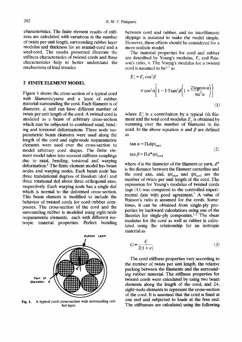
Figure 1 shows the cross-section of a typical cord with filaments/yarns and a layer of rubber material surrounding the cord. Each filament is of diameter, d, and can have different number of twists per unit length of the cord. A twisted cord is modeled as a beam of arbitrary cross-section which may be subjected to combined axial, bend- ing and torsional deformations. Three node iso- parametric beam elements were used along the length of the cord and eight-node isoparametric elements were used over the cross-section to model arbitrary cord shapes. The finite ele- ment model takes into account stiffness couplings due to axial, bending, torsional and warping deformation. 6 The finite element model has beam nodes and warping nodes. Each beam node has three translational degrees of freedom (dof) and three rotational dof about three orthogonal axes, respectively. Each warping node has a single dof which is normal to the deformed cross-section. This beam element is modified to include the behavior of twisted cords for cord-rubber com- posites. The cross-section of the cord and the surrounding rubber is modeled using eight-node isoparametric elements, each with different iso- tropic material properties. Perfect bonding
Rubber Layer
E i. = Ef cos4fl
os o[l_ . tan2 ( 21ogcos a l l
(1)
where E~ is a contribution by a typical ith fila- ment and the total cord modulus E c is obtained by summing over the number of filaments in the cord. In the above equation a and fl are defined as
tan a = 1 - I d t p i y a r n
tan fl = Hd*tpicorO (2)
where d is the diameter of the filament or yarn, d* is the distance between the filament centerline and the cord axis, and, tpiya~ and tpicora are the number of twists per unit length of the cord. The expression for Young's modulus of twisted cords (eqn (1)) was compared to the controlled experi- mental data with good agreement] A value of Poisson's ratio is assumed for the cords. Some- times, it can be obtained from single-ply pro- perties by backward calculations using one of the theories for single-ply composites. 1,2 The shear modulus for the cord as well as rubber is calcu- lated using the relationship for an isotropic material as
E 6 = - (3)
2(1 + v)
Yarn of Diameter, ¢
Fig. 1. A typical cord cross-section with surrounding rub- ber layer.
The cord stiffness properties vary according to the number of twists per unit length, the relative packing between the filaments and the surround- ing rubber material. The stiffness properties for twisted cords were calculated by using two beam elements along the length of the cord, and 24, eight-node elements to represent the cross-section of the cord. It is assumed that the cord is fixed at one end and subjected to loads at the free end. The stiffnesses are calculated using the following
Stiffness characteristics of twisted cords for cord-rubber composites 293
expressions:
Axial Stiffness (EA) = applied load x length/ axial displacement Bending Stiffness (El) = applied load x length3/ 3 x vertical displacement Torsional Stiffness (GJ)=torsional moment x length/rotational angle
For example, when a twisted cord is subjected to an axial load, there will be bending and twisting deformations in addition to the tensile deforma- tion. The present finite element model will give these three displacements as a part of the dof. The axial stiffness (EA) is calculated from the axial dof using the above expression. The bending-exten- sion and twisting-extension stiffness couplings are calculated by using the ratio of bending dof to axial dof, and rotational dof to axial dof, respect- ively. The same procedure is used for calculating the extension-twisting and the bending-twisting stiffness couplings for a cord when subjected to a torsional moment.
3 RESULTS AND DISCUSSION
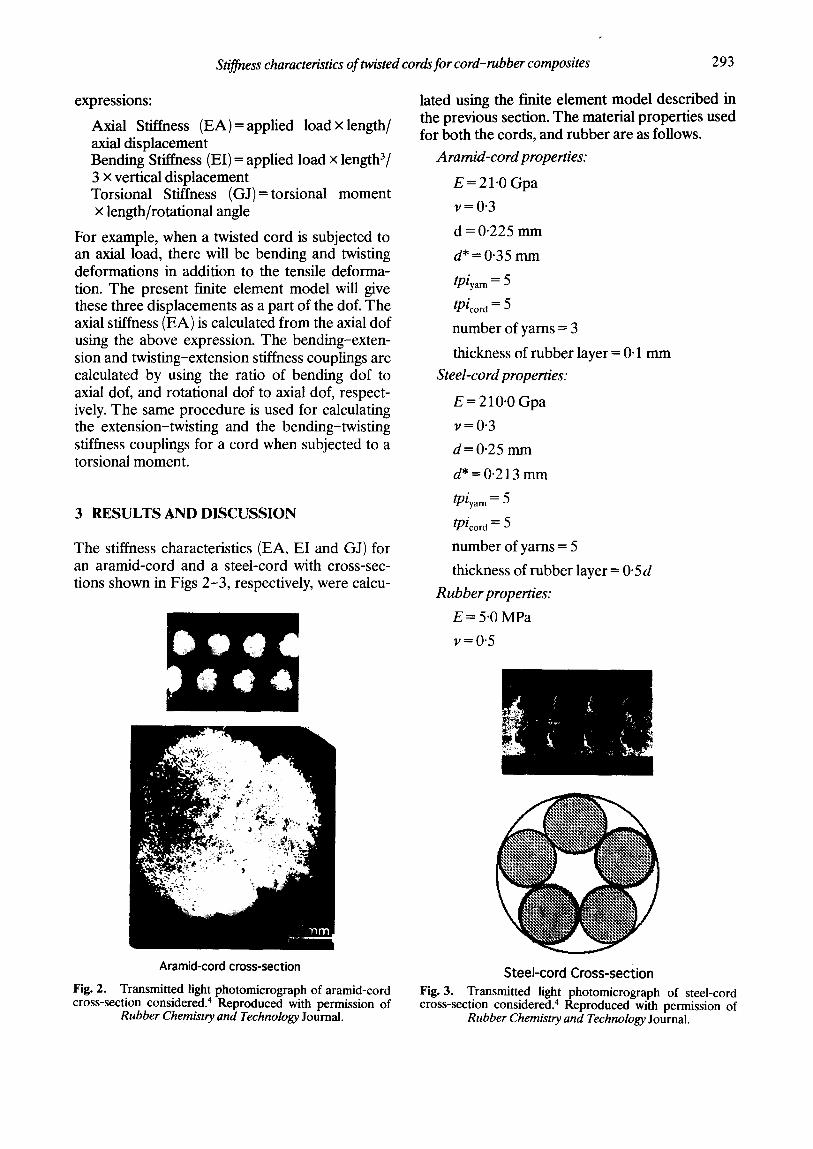
The stiffness characteristics (EA, EI and GJ) for an aramid-cord and a steel-cord with cross-sec- tions shown in Figs 2-3, respectively, were calcu-
I O Q d D o e 4
lated using the finite element model described in the previous section. The material properties used for both the cords, and rubber are as follows.
Aramid-cord properties:
E = 21.0 Gpa
v=0 .3
d = 0.225 mm
d* = 0.35 mm
tpiyar n = 5
tpicora = 5
number of yarns = 3
thickness of rubber layer = 0"1 mm
Steel-cord properties:
E = 210"0 Gpa
v=0 .3
d = 0.25 mm
d* = 0.213 mm
tpiyarn=5 tpicord = 5
number of yarns = 5
thickness of rubber layer = 0"5d
Rubber properties:
E = 5"0 MPa
v=0 .5
Aramid-cord cross-section
Fig. 2. Transmitted light photomicrograph of aramid-cord cross-section considered. 4 Reproduced with permission of
Rubber Chemistry and Technology Journal.
Steel-cord Cross-section Fig. 3. Transmitted light photomicrograph of steel-cord cross-section considered. 4 Reproduced with permission of
Rubber Chemistry and Technology Journal.

294 R. M. V. Pidaparti
The axial, bending, and torsional stiffnesses were calculated by applying an axial load, a vertical load and a torsional moment independently. As there are no experimental or analytical results of stiffness characteristics available for comparison, approximate expressions were used to compare the results of the finite element analysis. The approximate expressions for stiffnesses were cal- culated using the following equations:
E A = E t A c .Jr E r A r
EI -- EJc + ErI r
GJ = G~J~ + GrJ r
where Ac, Ic, and Jc are the area, moment of inertia, and polar moment of inertia of the cord, respectively. Similarly, A r, Ir, and Jr are the area, moment of inertia, and polar moment of inertia of the surrounding rubber layer, respectively.
Figures 4-6 show the axial, bending, and tor- sional stiffnesses, respectively, for the aramid cord along with the approximate expressions for various number of twists per unit length (tpl) of the cord. The results were based on the actual cross-section (Fig. 2), and an idealized circular cross-section with diameter of 0.45 mm. The approximate expressions were calculated based on the idealized cross-section. It can be seen from Figs 4-6 that all the three stiffnesses decrease as the number of twists per unit length are increased. The stiffness values for the actual cross-section are lower than the idealized cross-section for the aramid-cord because the idealized cross-section is larger than the actual cross-section. The results of
axial stiffness agree well with the approximate expression for higher values of tpl (tpl>6) as compared to lower values (tpl < 5). The results of bending stiffness agree quite well with the approximate expression (see Fig. 5). It can be seen from Fig. 6 that the present approximate expres- sion for torsional stiffness is not in good agree- ment with the results of the finite element analysis. Also, there is some difference (for higher values of tpl as compared to lower values of tpl) between stiffness values based on the actual and ideal cross-sections. One has to be careful in using the approximate expression for torsional stiffness of cords with arbitrary cross-sections.
uJ
e (/}
r -
O~ e -
e-
t n
Fig. 5.
10.
8 •
o 0 I d e a l C r o s s - s e c t i o n
A A c t u a l C r o s s - s e c t i o n
- - Approx. Eipression
i i
2 ; ; ; l o
Twists per unit length
Variation of bending stiffness (EI) with number of twists per unit length for the aramid-cord.
A < ILl
t/J
e- q , . q . .
tn
X <
Fig. 4.
200
150 '
100
50 ¸
0 0
O Ideal Cross-section OA~ A Actual Cross-section
Approx. Eipression
i i i | i
2 4 6 8 10
Twists per unit Length
Variation of axial stiffness (EA) with number of twists per unit length for the aramid-cord.
A
O v
¢/J
e-
t t - -
m
t~ t - O
l t .
O I ' -
Fig. 6.
12 0
10"
S '
6 -
4 -
2 '
A 0 Ideal Cross-section A Actual Cross-section
Approx. Expression
Aramid-cord
• i
12
Twists per unit length
Variation of torsional stiffness (GJ) with number of twists per unit length for the aramid-cord.

Stiffness characteristics of twisted cords for cord-rubber composites 2 9 5
The bending stiffness of the steel-cord (see Fig. 3) is shown in Fig. 7 along with the approximate expression. A good agreement is seen. However, it should be mentioned that the present approxi- mate expressions predict much higher values than the finite element results for axial and torsional stiffnesses. Once again, one should be careful in using these approximate expressions for different types of cord. Using the same steel-cord cross- section but with aramid-cord properties, the axial, bending, and torsional stiffnesses were calculated to compare the relative stiffness of steel and aramid cords. The finite element results of stiff- ness ratios d (EA/EI), and /~ (EA/GJ) are pre- sented in Fig. 8 with tpl varying from two to 10. For both the cords, the stiffness ratios 6 and fl increase as the number of tpl are increased. For the arami_d-cord, the value of 6 is higher than the value of fl, and the difference between these two is approximately constant (about 22%) for the number of tpl considered. However, for the steel- cor_d, the value of 6 is much higher than the value of fl, and the difference between them increases rapidly as the number of tpl is increased. For the same cord construction, the stiffness ratios 6 and /~ are higher for the aramid-cord as compared to the steel-cord. The results presented in Fig. 8 indicate that stiffer cord materials have higher bending and torsional stiffnesses for higher numbers of tpl.
Figur_e 9 shows the variation of stiffness ratios (6 and fl) with increasing values of the surround- ing rubber modulus. It is very interesting to see that both the ratios a and fl decrease as the value
of the rubber modulus is increased from 10 to 1000 MPa. However, for the steel-cord, both ti and/~ increase rapidly up to a rubber modulus of 100 MPa and then decrease slowly afterwards. The value of ti is lower for the steel cord than the aramid-cord up to a rubber modulus of 50 MPa, and then onwards the value of ti is higher for the steel-cord than the aramid-cord. However, the value of/~ is higher for the aramid-cord as com- pared to the steel-cord for the modulus values of the rubber considered. The effect of increasing the surrounding rubber modulus over cords after a particular value has no effect on stiffness pro- perties (see Fig. 9).
<
A
UJ
30
20
10 ¸
J - ~ O ~ (F_A/EI) Aramid-cord p ~ (ENGJ) Aramid-cord
/ ~ (EA/EI) Steel-cord & (ENGJ) Steel-cord
2 4 6 8 10 1 2
Twists per unit length
Fig. 8. Variation of (EA/EI) and (EA/GJ) with number of twists per unit length for the aramid-cord and the steel-cord.
A m
t t l v
t , - t i -
m
U ~ e -
e -
Fig. 7.
300
200
100 '
O Actual Cross-section O ~ Approx. Expression
Twists per unit length Variation of bending stiffness (EI) with number of
twists per unit length for the steel-cord.
30.
A
o ,< I i i 20.
A 14,1 < ILl 10
)
(ENGJ) Aramid-cord ~. (ENEI) Steel-cord .L (ENGJ) Steel-cord
" - - " ,I, ,I,
0 200 400 600 800 1000 1200
Rubber Modulus (Mpa)
Fig. 9. Variation of (EA/EI) and EA/GJ) with surrounding rubber modulus for the aramid-cord and the steel-cord.

296 R. M. V. Pidaparti
Figure 10 shows bending-extension and twist- ing-extension stiffness couplings for the aramid- cord when subjected to an axial load. It can be seen that the bending-extension couplings decrease rapidly as the number of tpl are increased, whereas the increase in twisting-exten- sion coupling is very little. For the aramid-cord considered, the bending-extension coupling is greater than the twisting-extension coupling up to 6 tpl and then onwards twisting-extension coupl- ing dominates the bending-extension coupling. Similarily, the extension-twisting and bending- twisting couplings are shown in Fig. 11 for the aramid-cord when subjected to a torsional moment. The extension-twisting coupling increases as the number of tpl are increased whereas the bending-twisting coupling decreases upto 8 tpl and then increases thereafter. However, bending-twisting coupling is much stronger than extension-twisting coupling for all the numbers of tpl considered. The difference between bending- twisting and extension-twisting stiffness coupling decreases as the number of tpl are increased. It can be seen from Figs 10 and 11 that the amount and type of stiffness couplings depend on the number of tpl and the load. The mechanism of load (bending or extension or torsion) transfer for the cord depends strongly on the number of tpl used for the cord. The applied axial load is trans- ferred through bending action for a smaller number of tpl (< 6) and through twisting action for a higher number of tpl. However, for an applied torsional load, the mechanism of load transfer occurs through bending action for a
smaller number of tpl. But, for a higher number of tpl, the load transfer occurs through both bending as well as extension.
To see how the surrounding rubber layer thick- ness affects the stiffness characteristics, five dif- ferent thicknesses were considered for the aramid-cord (_see Fig. 2). The variation of stiffness ratios 6 and fl with rubber thickness is presented_ in Fig. 12. Both the stiffness ratios 6 and fl decrease as the surrounding rubber layer thick- ness is increased. However, the value of ratio d is higher than that of ft. The difference between 6 and fl decreases as the value of the rubber thick- ness increases. Figures 13 and 14 show the stiff- ness couplings for the aramid-cord when
0.11
0.10
C o~
~ " o.og -
0 tO
t,t)
¢Z
, D
0.08
0.07
0.06
0,05
0 1 2
O--- Extension-twisting
~" g~i~'~i -d~clti~ g
2 4 6 8 1 0
Twists per unit length Fig. 11. Variation of extension-twisting and bending- twisting coupling with number of twists per unit length for
the aramid-cord.
2 '
O.
0 0
4)
m
Bending-extension • , Twisting-extension
~ i ~ A r a m i d ' c ° r d
i
4 6 8 1 0
Twists per unit length
Fig. 10. Variation of bending-extension and twisting- extension coupling with number of twists per unit length for
the aramid-cord.
16
O < IJJ
m u,I < LU
14
12
10
8 0.0 0.3
O-- (ENEI) - )
Aramid-cord
i !
0.1 O.2
Rubber Thickness (mm) Fig. 12. Variation of (EA/EI) and (EA/GJ) with surround-
ing rubber layer thickness for the aramid-cord.

Stiffness characteristics of twisted cords for cord-rubber composites 297
0.76
O~
C
o o
q) r "
¢n
0.74
0.72
0.70
0.68 0 .0 0 .3
~ -cord
0.1 0 .2
Rubber Thickness (mm) Fig. 13. Variation of bending-extension and twisting- extension coupling with rubber layer thickness for the
aramid-cord.
than the extension-twisting coupling for the range of rubber thickness values considered. It can be seen from Figs 13 and 14 that the stiffness coup- lings strongly depend on the thickness values of the surrounding rubber, and that this dependence may be reflected in the failure mechanisms or load transfer mechanisms of twisted cords. The mechanisms of load transfer or failure operate through twisting action for lower values of sur- rounding rubber thickness for an axial load, and through bending action for a torsional load. How- ever, for larger values of surrounding rubber thickness, bending stiffness contributes more than twisting stiffness for an axial load whereas bend- ing stiffness contributes more than axial stiffness for a torsional load.
4 CONCLUDING REMARKS
O~ c" w
"-z
O O
(R W ¢D r "
0.18
0.16 -
0.14 -
0 . 1 2
0.10'
0.08'
O ~ Extension-twisting Bending-twisting
0.06 0.0 0 .3
9"" 011 012
Rubber Thickness (mm) Fig. 14. Variation of extension-twisting and bending- twisting coupling with rubber layer thickness for the aramid-
Cord.
subjected to an axial load and a torsional moment, respectively. The bending-extension coupling increases whereas the twisting-extension coupling decreases as the value of the rubber thickness is increased. The twisting-extension coupling is greater than the bending-extension coupling for smaller values of rubber thickness. The difference between them decreases as the rubber thickness value is increased, thereby changing the trend completely (see Fig. 13). It can be seen from Fig. 14 that the values of bending-twisting coupling, and extension-twisting coupling increase as the value of the rubber thickness is increased. How- ever, the bending-twisting coupling is stronger
A finite element model is developed to predict the stiffness characteristics of twisted cords by treat- ing them as structures and taking into account the stiffness couplings due to extension-bending- torsional deformations. The finite dement results of axial, bending, and torsional stiffness are com- pared to approximate expressions with good agreement except for torsion for the aramid-cord considered. The bending stiffness of the sted- cord agreed well with the approximate expression. The relative stiffnesses between axial-bending and axial-torsion are presented for the aramid-cord and the steel-cord with variations in the number of twists per unit length and rubber modulus (Figs 8 and 9). The stiffness couplings among bend- ing-extension-twisting are presented with varia- tions in the number of twists per unit length and surrounding rubber thickness values for the aramid-cord (see Figs 10, 11, 13 and 14). The presented results illustrate that the stiffness characteristics of twisted cords are strongly dependent upon the number of twists per unit length, type of cord, surrounding rubber layer thickness and modulus. The stiffness couplings presented illustrate the mechanisms of load trans- fer, which are important for understanding failure mechanisms of cords, and cord-rubber compo- sites.
A C K N O W L E D G E M E N T S
This research was supported by the US National Science Foundation under the grant MSS- 9109683.

298 R. M. V. Pidaparti
REFERENCES
1. Parhizgar, S., Weissman, E. M. & Chen, C. S., Determina- tion of stiffness properties of single-ply cord-rubber com- posites. Tire Sci. Technol., 16 (1988) 118 -26.
2. Walter, J. D. & Patel, H. P., Approximate expressions for the elastic constants of cord-rubber laminates. Rubber Chem. Technol. J., 52 (1979) 710-24.
3. Moghe, S. R., Presentation at Fiber Society Meeting, Raleigh, NC, USA, 1982.
4. Cembrola, R. J. & Dudek, T. J., Cord/rubber material properties. Rubber Chem. Technol. J., 58 ( 1985) 830- 56.
5. Akasaka, T., Kabe, K. & Sako, K., Bending stiffness of a tire belt structure with steel cords. Comp. Sci. Technol. Z, 24 (1985) 215-30.
6. Lee, S. W. & Kim, Y. H., A new approach to the finite ele- ment modeling of beams with warping effect. Int. J. Numerical Meth. Engng, 24 (1987) 2327-41.
7. Moghe, S. R., Design of fabric reinforced composites. In Textile Structural Composites (Vol. 3), ed. T. S. Chou & F. K. Ko. Elsevier Science Publishers, Ltd, London, UK, 1990, pp. 355-77.