stick-slip training guide
TRANSCRIPT
7/26/2019 Stick-slip Training Guide
http://slidepdf.com/reader/full/stick-slip-training-guide 1/54
Baker Hughes INTEQ
Stick-Slip
A DrillByte Applications
Training Guide
80971 Rev. A June 1995
Baker Hughes INTEQTraining and Development2520 WW ThorneHouston, TX 77073USA713-625-4890

7/26/2019 Stick-slip Training Guide
http://slidepdf.com/reader/full/stick-slip-training-guide 2/54
7/26/2019 Stick-slip Training Guide
http://slidepdf.com/reader/full/stick-slip-training-guide 3/54
Training Guide i80971 Rev. A / June 1995 Confidential
Table of Contents
Table of Contents
Chapter 1
Stick-Slip BasicsIntroduction . . . . . . . . . . . . . . . . . . . . . . . . . . . . . . . . . . . . . . . . . . . . . . . . . . . . . 1-1
Theoretical Background. . . . . . . . . . . . . . . . . . . . . . . . . . . . . . . . . . . . . . . . . . . . 1-2
Surface Detection. . . . . . . . . . . . . . . . . . . . . . . . . . . . . . . . . . . . . . . . . . . . . . . . . 1-3
Chapter 2
The Stick-Slip Program
Introduction . . . . . . . . . . . . . . . . . . . . . . . . . . . . . . . . . . . . . . . . . . . . . . . . . . . . . 2-1
Stick-Slip Monitor Design . . . . . . . . . . . . . . . . . . . . . . . . . . . . . . . . . . . . . . . . . . 2-1
Monitor Start-Up . . . . . . . . . . . . . . . . . . . . . . . . . . . . . . . . . . . . . . . . . . . . . . . . . 2-2
Monitor Operation . . . . . . . . . . . . . . . . . . . . . . . . . . . . . . . . . . . . . . . . . . . . . . . . 2-4
Optional Operations . . . . . . . . . . . . . . . . . . . . . . . . . . . . . . . . . . . . . . . . . . . . . . . 2-6
Chapter 3
Curing Stick-Slip ProblemsIntroduction . . . . . . . . . . . . . . . . . . . . . . . . . . . . . . . . . . . . . . . . . . . . . . . . . . . . . 3-1
Causes of Stick Slip . . . . . . . . . . . . . . . . . . . . . . . . . . . . . . . . . . . . . . . . . . . . . . . 3-1Cures For Stick Slip. . . . . . . . . . . . . . . . . . . . . . . . . . . . . . . . . . . . . . . . . . . . . . . 3-2
Immediate Actions Possible . . . . . . . . . . . . . . . . . . . . . . . . . . . . . . . . . . . 3-2
Actions Possible at Trip Time . . . . . . . . . . . . . . . . . . . . . . . . . . . . . . . . . 3-2
Rig and Well Design Issues . . . . . . . . . . . . . . . . . . . . . . . . . . . . . . . . . . . 3-2
7/26/2019 Stick-slip Training Guide
http://slidepdf.com/reader/full/stick-slip-training-guide 4/54
ii Baker Hughes INTEQConfidential 80971 Rev. A / June 1995
Table of Contents Stick-Slip
Appendicies
Appendix A
Modifications to the P&F Rack for Stick-Slip Monitoring
Appendix B
Files Used in the Stick-Slip Program
Appendix C
References
Appendix DStick-Slip Examples
Appendix E
Recommended Stick-Slip Set Points
7/26/2019 Stick-slip Training Guide
http://slidepdf.com/reader/full/stick-slip-training-guide 5/54
Training Guide 1-180971 Rev A / June 1995 Confidential
Chapter 1
Stick-Slip Basics
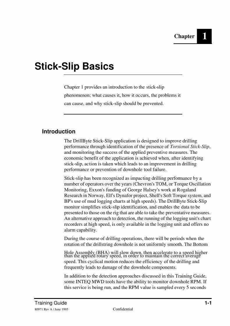
Chapter 1 provides an introduction to the stick-slip
phenomenon; what causes it, how it occurs, the problems it
can cause, and why stick-slip should be prevented.
Introduction
The DrillByte Stick-Slip application is designed to improve drillingperformance through identification of the presence of Torsional Stick-Slip,and monitoring the success of the applied preventive measures. Theeconomic benefit of the application is achieved when, after identifyingstick-slip, action is taken which leads to an improvement in drillingperformance or prevention of downhole tool failure.
Stick-slip has been recognized as impacting drilling performance by anumber of operators over the years (Chevron's TOM, or Torque Oscillation
Monitoring, Exxon's funding of George Halsey's work at RogalandResearch in Norway, Elf's Dynafor project, Shell's Soft Torque system, andBP's use of mud logging charts at high speeds). The DrillByte Stick-Slipmonitor simplifies stick-slip identification, and enables the data to bepresented to those on the rig that are able to take the preventative measures.An alternative approach to detection, the running of the logging unit's chartrecorders at high speed, is only available in the logging unit and offers noalarm capability.
During the course of drilling operations, there will be periods when the
rotation of the drillstring downhole is not uniformly smooth. The Bottom
Hole Assembly (BHA) will slow down, then accelerate to a speed higherthan the applied rotary speed, in order to maintain the correct averagespeed. This cyclical motion reduces the efficiency of the drilling andfrequently leads to damage of the downhole components.
In addition to the detection approaches discussed in this Training Guide,some INTEQ MWD tools have the ability to monitor downhole RPM. Ifthis service is being run, and the RPM value is sampled every 5 seconds
7/26/2019 Stick-slip Training Guide
http://slidepdf.com/reader/full/stick-slip-training-guide 6/54
1-2 Baker Hughes INTEQConfidential 80971 Rev A / June 1995
Stick-Slip Basics Stick-Slip
(rather than an average) the variation in spot readings can be very usefulwhen used in conjunction with the DrillByte Stick-Slip monitor.
Theoretical Background
The sticking and slipping of the drillstring (known as rotational or torsionalstick-slip) is an important dynamic phenomena which can result in
premature bit wear, drill pipe fatigue, premature failure of downholemotors, and can induce other detrimental drillstring dynamics. This"torsional" stick-slip should not be confused with “axial” stick-slip duringsliding (which is due to friction acting axially along the drill string,resulting in intermittent bit loading) because torsional stick-slip is due todynamic and static friction between the BHA and borehole wall, which is
impeding the steady-state rotation of the BHA.
In the theoretical examination of torsional stick-slip, the drillstring may bethought of as a torsional spring (drill pipe) and a lumped mass (BHA).
When rotation commences at the surface, the lumped mass will tend to lagbehind until sufficient torque is built up to overcome the inertia of the massand any additional frictional forces that may be present.
The rotational speed of the mass will tend to oscillate around the surfacerotary speed (these oscillations will eventually stop) until the bit's rotaryspeed matches the surface rotary speed.
The oscillations described above are known as torsional oscillations. Theperiod of one oscillation (depending on the length's of the drillpipe andBHA, and their respective diameters) will generally range between 2 to 15seconds. Stick-slip is a severe and persistent case of these torsional
oscillations, whereby the BHA comes to a complete stop and then suddenlyreleases at a high rate of speed.
This torsional stick-slip is due to higher static than dynamic friction levels
which impedes the rotation of the BHA and bit. These high static frictionlevels are caused by various drilling phenomena, such as:
• the buckling or whirling of the BHA
• the aggressive cutting action of a PDC bit
• lithology changes
• contact between stabilizers and the borehole wall• abruptly starting the bit on bottom
When sufficient torque is developed in the string to overcome this staticfriction, the drillstring will initially rotate rapidly, then slow down. It will
stop again when its rotational velocity drops below some critical value,bringing static friction back into play.
7/26/2019 Stick-slip Training Guide
http://slidepdf.com/reader/full/stick-slip-training-guide 7/54
Training Guide 1-380971 Rev A / June 1995 Confidential
Stick-Slip Stick-Slip Basics
The period of this stick-slip phenomena is generally longer than thetorsional oscillation period, due to the time the bit is motionless. Eventhough the rotary speed at the bit (on average) will be the same as thesurface rotary speed, its instantaneous speed will vary from zero to morethan twice the surface speed, and can even become negative (backwards
rotation) in particularly severe cases.
Surface Detection
Depending on the type of rotary drive on the rig, detection will be mostapparent in either Torque or Rotary Speed or both. Though the DrillByteStick-Slip application was primarily designed for electric Top Drives orRotary Tables, it can be equally effective with hydraulic Top Drives.
Torque signals from the sensor is filtered to remove the high frequencysignal components (those events happening faster than twice a second),then the sensor reading is sampled to produce twenty-five plot points per
second, which is then passed to the display routine every two seconds.
There may be similar oscillations in rotary speed, although deviations from
the static value are generally minor. If an analog feed to a slow chartrecorder is used (i.e. rig floor drilling recorder), the trace may show a widertrack and the pen will visually oscillate from side to side, at a constant rate.If the output is to a heavily-damped analog chart recorder, the oscillationsof stick-slip can be completely removed.
If surface torque fluctuations are greater than 15% of the mean surfacetorque, there is a high probability that stick-slip is present and correctivemeasures should be taken. As stated earlier, the period of the stick-slip
fluctuations will depend on the length and mechanical properties of thedrillstring (i.e. for 5-inch drillpipe, the period of oscillation is about 2seconds per 1000 meters, or about 8 seconds for a 4000 meter drillstring).
In highly deviated wells, stick-slip type problems can be generated by thefrictional forces resulting from the BHA or drillstring rubbing against theborehole wall, rather than by the bit/formation interaction. In these cases,the stick-slip symptom will not disappear when coming off-bottom.
Surface stick-slip detection includes:
• surface torque fluctuations (including Top Drive stalling)
• increased torque cyclicity
• increased MWD shock counts
• cutter impact damage
• drillstring twist-off or washout
• connection over-torque or connection back-off

7/26/2019 Stick-slip Training Guide
http://slidepdf.com/reader/full/stick-slip-training-guide 8/54
1-4 Baker Hughes INTEQConfidential 80971 Rev A / June 1995
Stick-Slip Basics Stick-Slip
•Notes•
7/26/2019 Stick-slip Training Guide
http://slidepdf.com/reader/full/stick-slip-training-guide 9/54
Training Guide 2-180971 Rev A / June 1995 Confidential
Chapter 2
The Stick-Slip Program
Chapter 2 provides the information necessary for the
operator to understand the DrillByte Stick-Slip Application
program. Complete details of the program can be found in
Volume 1 of the DrillByte Reference Manuals (P/N
80319H-001).
Introduction
The applications program within DrillByte provides stick-slip detection by
monitoring the current applied to the electric motor running the RotaryTable or Top Drive. This signal is filtered and then sampled at 25 samplesper second. A detection algorithm will "look" for stick-slip by comparingthe calculated values to the operator set threshold controls. Monitor alarms
can be either audio or visual, and can include the automatic presentation ona workstation screen. The standard DrillByte plot package can be used to
create an emulation of the display screen for output to non X-terminaldispalys.
Stick-Slip Monitor Design
Incoming data is sampled at 125 data points per second, then reduced to 25points, to provide enough data points for graphical representations. TheDAQ will use a number of low-pass filters (hardware analog filters andsoftware digital filters) to prevent high frequencies from aliasing thesampled torque signals. Frequencies above 2.0 Hz are filtered out.
When the filtered data is transmitted from the DAQ to DrillByte, the dataacquisition daemon ( daqd ) buffers the incoming data. A flag (initialized tozero) is used to indicate the presence of new data. This flag is incrementedby daqd each time a new data set is received. This data set is located in the
DAQ Shared Memory and can be accessed by other DrillByte programs.The daqd also converts the torque sensor data into SI units.
7/26/2019 Stick-slip Training Guide
http://slidepdf.com/reader/full/stick-slip-training-guide 10/54
2-2 Baker Hughes INTEQConfidential 80971 Rev A / June 1995
The Stick-Slip Program Stick-Slip
Since significant changes in hookload can trigger the recording of stick-slip, another parameter, sigma hookload, is also monitored. Stick-sliprecording will occur if the RMS average hookload varies by more than thehookload delta setpoint. If the Total RPM is zero, only the hookload datais recorded. A separate flag within DrillByte is maintained for hookload.
Processing of the torque data involves sequentially passing each data pointthrough the stick-slip algorithm to determine if a stick-slip status is met.Averaging is used to reduce the status to two-second updates, then thestatus is stored in the DrillByte Common Data Area (E_ST_SLIP_ST).This status can appear as:
• No Application Running 0
• No Stick-Slip 1
• Possible Stick-Slip 2
• Definite Stick-Slip 3
When there is a stick-slip event change (i.e. from Possible Stick-Slip toDefinite Stick-Slip) or the hookload flag is met, data is stored in a time-stamped file in the $DBYTEHOME/ctl directory. Raw torque andprocessed Rotary Speed, Hookload, Pump Pressure, and the stick-slip flagare recorded. Each event is recorded in a new time-stamped file (i.e.Oct23941430.slip) and can be stored in the database. The recorded datacan also be imported back into the stick-slip program for review.
Monitor Start-Up
The Stick-Slip monitor is started from Launcher, by selecting Monitor :Stick-Slip, and can be run in two modes - Active or Passive.
In the "Active Mode", all stick-slip options are available to the operator,including the ability to modify parameters in the Set-Up menu and torecord data files. Only one Active Mode monitor can be run.
In the "Passive Mode", the stick-slip parameters are read (from the stslip.ctlfile) and cannot be modified. Stick-slip calculations will be made anddisplayed on the screen, but no data files will be stored. This passiveversion was designed for remote X-terminals and can be started from the Launcher menu “custom” line by typing: stick -p. Several Passive
mode monitors can be run with the one Active Mode monitor.When started, the stick-slip interface is a single window, with a control
panel for user input and the remaining part of the window for graphicaloutput (see Figure 2-1).
7/26/2019 Stick-slip Training Guide
http://slidepdf.com/reader/full/stick-slip-training-guide 11/54
Training Guide 2-380971 Rev A / June 1995 Confidential
Stick-Slip The Stick-Slip Program
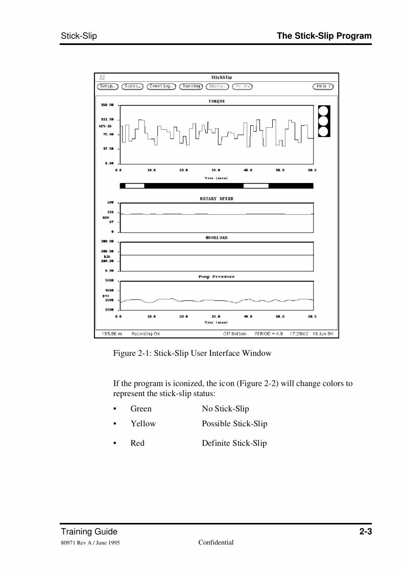
Figure 2-1: Stick-Slip User Interface Window
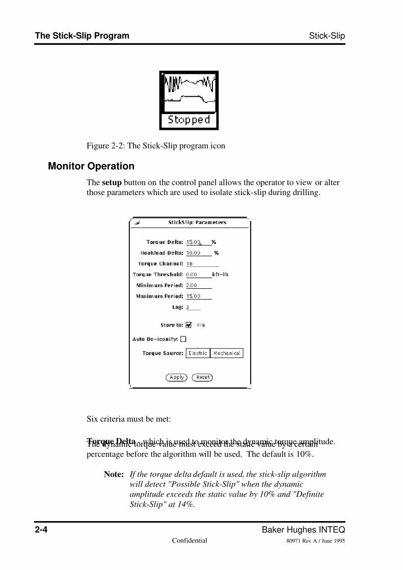
If the program is iconized, the icon (Figure 2-2) will change colors torepresent the stick-slip status:
• Green No Stick-Slip
• Yellow Possible Stick-Slip
• Red Definite Stick-Slip
7/26/2019 Stick-slip Training Guide
http://slidepdf.com/reader/full/stick-slip-training-guide 12/54
2-4 Baker Hughes INTEQConfidential 80971 Rev A / June 1995
The Stick-Slip Program Stick-Slip
Figure 2-2: The Stick-Slip program icon
Monitor Operation
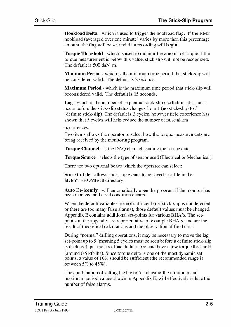
The setup button on the control panel allows the operator to view or alterthose parameters which are used to isolate stick-slip during drilling.
Six criteria must be met:
Torque Delta - which is used to monitor the dynamic torque amplitude.The dynamic torque value must exceed the static value by a certainpercentage before the algorithm will be used. The default is 10%.
Note: If the torque delta default is used, the stick-slip algorithm
will detect "Possible Stick-Slip" when the dynamic
amplitude exceeds the static value by 10% and "Definite
Stick-Slip" at 14%.
7/26/2019 Stick-slip Training Guide
http://slidepdf.com/reader/full/stick-slip-training-guide 13/54
Training Guide 2-580971 Rev A / June 1995 Confidential
Stick-Slip The Stick-Slip Program
Hookload Delta - which is used to trigger the hookload flag. If the RMShookload (averaged over one minute) varies by more than this percentageamount, the flag will be set and data recording will begin.
Torque Threshold - which is used to monitor the amount of torque.If the
torque measurement is below this value, stick slip will not be recognized.The default is 500 daN_m.
Minimum Period - which is the minimum time period that stick-slip willbe considered valid. The default is 2 seconds.
Maximum Period - which is the maximum time period that stick-slip will
beconsidered valid. The default is 15 seconds.
Lag - which is the number of sequential stick-slip oscillations that mustoccur before the stick-slip status changes from 1 (no stick-slip) to 3(definite stick-slip). The default is 3 cycles, however field experience hasshown that 5 cycles will help reduce the number of false alarm
occurrences.
Two items allows the operator to select how the torque measurements arebeing received by the monitoring program.
Torque Channel - is the DAQ channel sending the torque data.
Torque Source - selects the type of sensor used (Electrical or Mechanical).
There are two optional boxes which the operator can select:
Store to File - allows stick-slip events to be saved to a file in the$DBYTEHOME/ctl directory.
Auto De-iconify - will automatically open the program if the monitor hasbeen iconized and a red condition occurs.
When the default variables are not sufficient (i.e. stick-slip is not detectedor there are too many false alarms), those default values must be changed.Appendix E contains additional set-points for various BHA’s. The set-points in the appendix are representative of example BHA’s, and are theresult of theoretical calculations and the observation of field data.
During “normal” drilling operations, it may be necessary to move the lagset-point up to 5 (meaning 5 cycles must be seen before a definite stick-slipis declared), put the hookload delta to 5%, and have a low torque threshold
(around 0.5 kft-lbs). Since torque delta is one of the most dynamic setpoints, a value of 10% should be sufficient (the recommended range isbetween 5% to 45%).
The combination of setting the lag to 5 and using the minimum andmaximum period values shown in Appendix E, will effectively reduce thenumber of false alarms.
7/26/2019 Stick-slip Training Guide
http://slidepdf.com/reader/full/stick-slip-training-guide 14/54
2-6 Baker Hughes INTEQConfidential 80971 Rev A / June 1995
The Stick-Slip Program Stick-Slip
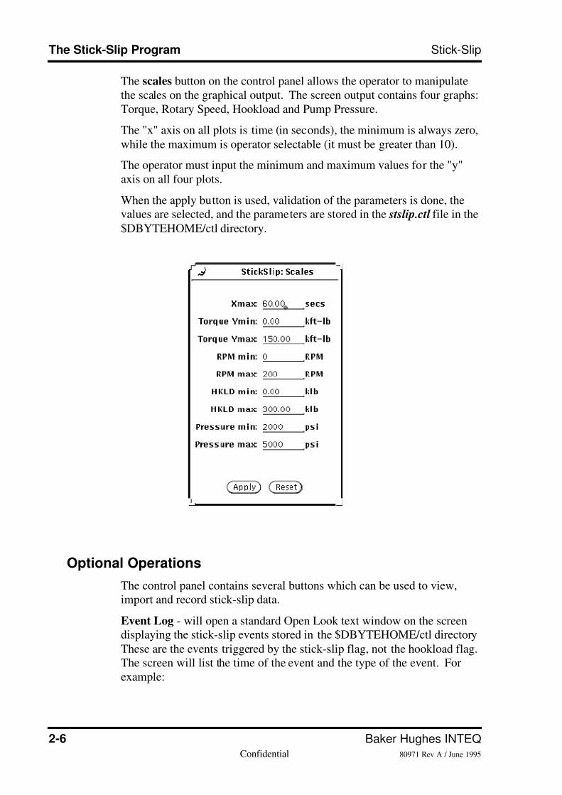
The scales button on the control panel allows the operator to manipulatethe scales on the graphical output. The screen output contains four graphs:Torque, Rotary Speed, Hookload and Pump Pressure.
The "x" axis on all plots is time (in seconds), the minimum is always zero,
while the maximum is operator selectable (it must be greater than 10).
The operator must input the minimum and maximum values for the "y"axis on all four plots.
When the apply button is used, validation of the parameters is done, thevalues are selected, and the parameters are stored in the stslip.ctl file in the
$DBYTEHOME/ctl directory.
Optional Operations
The control panel contains several buttons which can be used to view,import and record stick-slip data.
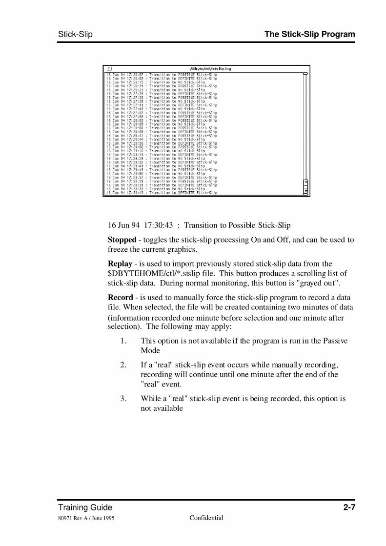
Event Log - will open a standard Open Look text window on the screendisplaying the stick-slip events stored in the $DBYTEHOME/ctl directory
These are the events triggered by the stick-slip flag, not the hookload flag.The screen will list the time of the event and the type of the event. Forexample:
7/26/2019 Stick-slip Training Guide
http://slidepdf.com/reader/full/stick-slip-training-guide 15/54
Training Guide 2-780971 Rev A / June 1995 Confidential
Stick-Slip The Stick-Slip Program
16 Jun 94 17:30:43 : Transition to Possible Stick-Slip
Stopped - toggles the stick-slip processing On and Off, and can be used tofreeze the current graphics.
Replay - is used to import previously stored stick-slip data from the$DBYTEHOME/ctl/*.stslip file. This button produces a scrolling list ofstick-slip data. During normal monitoring, this button is "grayed out".
Record - is used to manually force the stick-slip program to record a datafile. When selected, the file will be created containing two minutes of data
(information recorded one minute before selection and one minute afterselection). The following may apply:
1. This option is not available if the program is run in the PassiveMode
2. If a "real" stick-slip event occurs while manually recording,recording will continue until one minute after the end of the"real" event.
3. While a "real" stick-slip event is being recorded, this option isnot available

7/26/2019 Stick-slip Training Guide
http://slidepdf.com/reader/full/stick-slip-training-guide 16/54
2-8 Baker Hughes INTEQConfidential 80971 Rev A / June 1995
The Stick-Slip Program Stick-Slip
•Notes•
7/26/2019 Stick-slip Training Guide
http://slidepdf.com/reader/full/stick-slip-training-guide 17/54
Training Guide 3-180971 Rev A / June 1995 Confidential
Chapter 3
Curing Stick-Slip Problems
When stick-slip problems are detected, they must be cured
before drillstring damage occurs. Chapter 3 lists the cures
necessary when problems are identified.
Introduction
Once stick-slip is identified, action is required to address the problem.Some steps can be taken immediately, others may require a bit trip or rigmodifications on a longer time scale. The first step is to determine thepotential causes of stick slip, and the correct action to cure it. It has beennoted that when the Stick Slip displays a saw tooth pattern, that this can bean indication that the Stick Slip is driven by the bit, rather than a smoother
sine wave, seen with stabilizers or drillstring contact. This can be a usefulguide, through it is not yet proven
Causes of Stick Slip
Factors causing Stick Slip can be grouped into three general categories:
• Category #1
Excessive stabilizer or BHA side loading from a buckled Bottom HoleAssembly. This is especially common when drilling with very high bitweights, or with very limber assemblies (i.e. slimhole drilling).
• Category #2
a. Stabilizer and/or BHA friction from excessive hole tortuosity.b. Excessive weight on PDC bits for the formation type or rock propertiesencountered. If too large a "bite" is being taken by the bit, the stallingaction may cause stick slip.
• Category #3
Lack of fluid lubrication. Poor drilling fluid properties or excessivecuttings build-up can be a factor in promoting stick slip.
7/26/2019 Stick-slip Training Guide
http://slidepdf.com/reader/full/stick-slip-training-guide 18/54
3-2 Baker Hughes INTEQConfidential 80971 Rev A / June 1995
Curing Stick-Slip Problems Stick-Slip
Cures For Stick Slip
Based on what is causing the stick slip problems, the cure can beaccomplished quickly or it may require a bit trip.
Immediate Actions PossibleIt should be noted that "immediate" is not instantaneous. It may take a fewminutes for the effects of a change in drilling parameters to take effect. Insevere cases, to totally remove the problem, it may be necessary to stopdrilling, lift off bottom, stop rotating, and restart the drilling process.
Parameter Management - these steps are primarily aimed at reducing bitweight and/or increasing rotary speed. This is designed to address
categories 1 and 2.
For example; for a given PDC bit design, increasing the RPM will reducethe instantaneous depth of cut. Reducing the weight will also reduce the
side forces in a buckled BHA.
It may be necessary to both reduce weight and increase RPM.
Fluid Properties - Increase the lubricity of the drilling fluid.
Actions Possible at Trip Time
BHA Design - Add stabilization to increase buckling resistance. Substitute
roller reamers for stabilizers.
Bit Selection - Select a less aggressive bit or bit type.
Rig and Well Design Issues
Torque Feedback System - The rig can be modified to include a TorqueFeedback System
Dogleg Severity - Use downhole equipment which reduces wellboretortuosity.
7/26/2019 Stick-slip Training Guide
http://slidepdf.com/reader/full/stick-slip-training-guide 19/54
Training Guide A-180971 Rev A / June 1995 Confidential
Appendix A
Modifications to the P&F Rack forStick-Slip Monitoring
The P&F filter card (INTEQ P/N 81032, rev C) required modification in
order to be used with the DrillByte Stick-Slip Monitor. When modified,the cards are identified by the etched characters "EX#" (e.g. EX1, EX2 ...).In addition, the front panel of the P&F rack will be silked screened with"Filter Card". Channels one and two have the same characteristics as theorginal filter card, while the third channel provides signal conditioning for
the Torque signal from the standard three-wire torque sensor (INTEQ P/N80301H).
The original DAQ (INTEQ P/N 28950), does not provide for connection to
the outputs of the P&F filter card, and a back panel upgrade kit (INTEQ P/ N 80560H) is available to provide those connections to all P&F outputs.
As there are several "versions" of the P&F rack in use, some of which
provide for the three-wire sensor to the filter card, there is a simplemodification for those which do not have the filter card configuration. Thefollowing configurations of equipment (with the correct modifications) canbe used for stick-slip monitoring:
1. Modified P&F Mk3b with an upgraded DAQ
2. Modified P&F Mk3 or Mk3a with a standard DAQ*
3. Modified P&F Mk3 or Mk3a with an upgraded DAQ
The stick-slip program automatically notifies the DAQ of the presence ofthe application, which initiates the extra data transfer of 50 data pointsevery two seconds to the DrillByte application from the DAQ.
P&F Mk3 and Mk3a Modification
Remove the top of the unit by unscrewing the four allen-head screws.Swap the connectors in J43 and J42 on the Mother PCB (INTEQ P/N37596) after marking them with their original locations. Check that LK7,near J9, on the Mother PCB is connected between A and C. Replace thecover. Install an EGT101 card (INTEQ P/N 55202) in J9 and the modifiedfilter card in J17.
7/26/2019 Stick-slip Training Guide
http://slidepdf.com/reader/full/stick-slip-training-guide 20/54
A-2 Baker Hughes INTEQConfidential 80971 Rev A / June 1995
Modifications to the P&F Rack for Stick-Slip Monitoring Stick-Slip
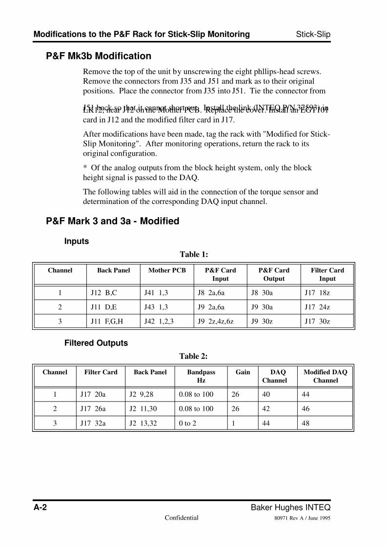
P&F Mk3b Modification
Remove the top of the unit by unscrewing the eight phllips-head screws.Remove the connectors from J35 and J51 and mark as to their originalpositions. Place the connector from J35 into J51. Tie the connector from
J51 back so that it cannot short out. Install the link (INTEQ P/N 37593) inLK12, near J12 on the Mother PCB. Replace the cover. Install an EGT101
card in J12 and the modified filter card in J17.
After modifications have been made, tag the rack with "Modified for Stick-Slip Monitoring". After monitoring operations, return the rack to itsoriginal configuration.
* Of the analog outputs from the block height system, only the block
height signal is passed to the DAQ.
The following tables will aid in the connection of the torque sensor anddetermination of the corresponding DAQ input channel.
P&F Mark 3 and 3a - Modified
Inputs
Filtered Outputs
Table 1:
Channel Back Panel Mother PCB P&F Card
Input
P&F Card
Output
Filter Card
Input
1 J12 B,C J41 1,3 J8 2a,6a J8 30a J17 18z
2 J11 D,E J43 1,3 J9 2a,6a J9 30a J17 24z
3 J11 F,G,H J42 1,2,3 J9 2z,4z,6z J9 30z J17 30z
Table 2:
Channel Filter Card Back Panel Bandpass
Hz
Gain DAQ
Channel
Modified DAQ
Channel
1 J17 20a J2 9,28 0.08 to 100 26 40 44
2 J17 26a J2 11,30 0.08 to 100 26 42 46
3 J17 32a J2 13,32 0 to 2 1 44 48
7/26/2019 Stick-slip Training Guide
http://slidepdf.com/reader/full/stick-slip-training-guide 21/54
Training Guide A-380971 Rev A / June 1995 Confidential
Stick-Slip Modifications to the P&F Rack for Stick-Slip Monitoring
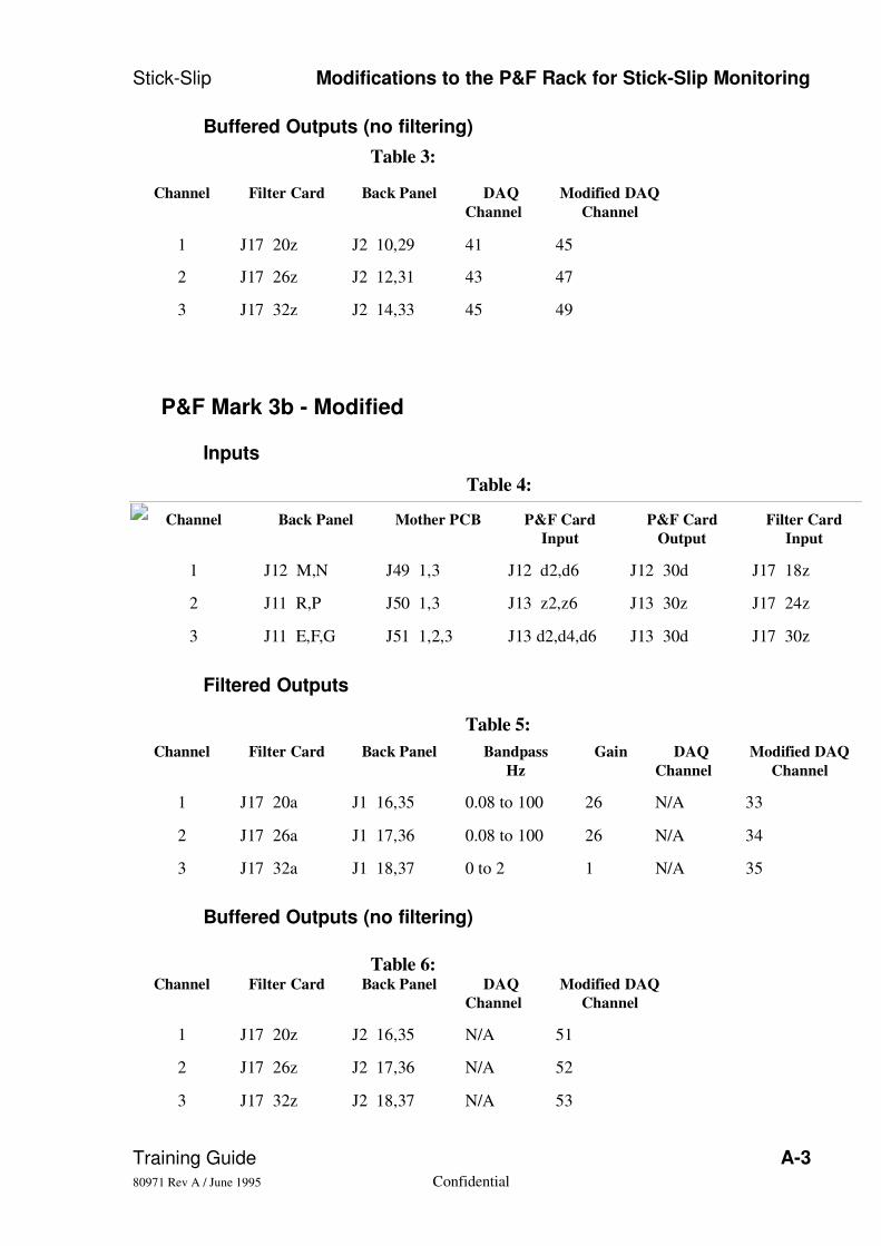
Buffered Outputs (no filtering)
P&F Mark 3b - Modified
Inputs
Filtered Outputs
Buffered Outputs (no filtering)
Table 3:
Channel Filter Card Back Panel DAQ
Channel
Modified DAQ
Channel
1 J17 20z J2 10,29 41 45
2 J17 26z J2 12,31 43 47
3 J17 32z J2 14,33 45 49
Table 4:
Channel Back Panel Mother PCB P&F Card
Input
P&F Card
Output
Filter Card
Input
1 J12 M,N J49 1,3 J12 d2,d6 J12 30d J17 18z
2 J11 R,P J50 1,3 J13 z2,z6 J13 30z J17 24z
3 J11 E,F,G J51 1,2,3 J13 d2,d4,d6 J13 30d J17 30z
Table 5:
Channel Filter Card Back Panel Bandpass
Hz
Gain DAQ
Channel
Modified DAQ
Channel
1 J17 20a J1 16,35 0.08 to 100 26 N/A 33
2 J17 26a J1 17,36 0.08 to 100 26 N/A 34
3 J17 32a J1 18,37 0 to 2 1 N/A 35
Table 6:Channel Filter Card Back Panel DAQ
Channel
Modified DAQ
Channel
1 J17 20z J2 16,35 N/A 51
2 J17 26z J2 17,36 N/A 52
3 J17 32z J2 18,37 N/A 53

7/26/2019 Stick-slip Training Guide
http://slidepdf.com/reader/full/stick-slip-training-guide 22/54
A-4 Baker Hughes INTEQConfidential 80971 Rev A / June 1995
Modifications to the P&F Rack for Stick-Slip Monitoring Stick-Slip
•Notes•
7/26/2019 Stick-slip Training Guide
http://slidepdf.com/reader/full/stick-slip-training-guide 23/54
Training Guide B-180971 Rev A / June 1995 Confidential
Appendix B
Files Used in the Stick-Slip Program
The following files in the $DBYTEHOME/ctl directory are used by theStick-Slip Monitoring Program.
stslip.ctl
This file contains the current parameters used by the stick-slip program.These are:
• Torque Threshold
• Torque Delta
• Hookload Delta
• Maximum Period
• Minimum Period
• Lag
• Xmax
• Torque Ymin
• Torque Ymax
• RPM Ymin
• RPM Ymax
• HKLD Ymin
• HKLD Ymax
timestamp.slip
These files store the stick-slip event data. This file is composed of threeparts, the first part contains:
• Month day year hour minute (e.g. Oct23941430.slip)
• Trigger/Time/Date (Torque or Hookload, hh:mm:ss:dd:mm:yy)
• Sample Rate
7/26/2019 Stick-slip Training Guide
http://slidepdf.com/reader/full/stick-slip-training-guide 24/54
B-2 Baker Hughes INTEQConfidential 80971 Rev A / June 1995
Files Used in the Stick-Slip Program Stick-Slip
• Torque Threshold
• Torque Channel
• Torque Delta
• Hookload Delta
• Maximum Period
• Minimum Period
• Lag
• Store Flag
• Torque Ymin
• Torque Ymax
• Hookload Ymin
• Hookload Ymax
• Pump Pressure Ymin
• Pump Pressure Ymax
• Rig Activity
• Bit Depth
The second part is composed of the time-stamp (unix time)
data 1
data 2
data 50
rpm value
hookload value
pump pressure value
stick-slip value
etc ... (this two-second data block format is repeated)
The final item in the file is a count of the two-second samplesSAMPLES = 87 (for a 174 second file)
7/26/2019 Stick-slip Training Guide
http://slidepdf.com/reader/full/stick-slip-training-guide 25/54
Training Guide C-180971 Rev A / June 1995 Confidential
Appendix C
References
Baker Hughes INTEQ, DrillByte Basics (DrillByte Volume 1, P/N
80319H-001) Rev. A, September 1994
Dufeyte, M.P., and Henneuse, H., Detection and Monitoring of the Slip-
Stick Motion: Field Experiments, SPE/IADC 21945, March 1991
Baker Hughes INTEQ, Technical Bulletin #1, April 1994
Abbassian, F., Drillstring Vibration Primer , BP Exploration, January 1994
Fear, M.J., and Abbassian, F., Experience in the Detection and Suppression
of Torsional Vibration From Mud Logging Data, SPE 28908, October1994
7/26/2019 Stick-slip Training Guide
http://slidepdf.com/reader/full/stick-slip-training-guide 26/54
C-2 Baker Hughes INTEQConfidential 80971 Rev A / June 1995
References Stick-Slip
SPE 28908
Experience in the Detection and Suppression of Torsional Vibration From Mud LoggingData1
M.J. Fear, BP Exploration Co. (Colombia) Ltd., and Fereidoun Abbassian, BP Exploration
SPE MembersCopyright 1994, Society of Petroleum Engineers, Inc.
This paper was prepared for presentation at the European Petroleum Conference held in London, U.K., 25-27
October 1994.
This paper was selected for presentation by an SPE Program Committee following review of information
contained in an abstract submitted by the author(s). Contents of the paper, as presented, have not been reviewed
by the Society of Petroleum Engineers and are subject to correction by the author(s). The material, as presented,
does not necessarily reflect any position of the Society of Petroleum Engineers, its officers, or members. Papers
presented at SPE meetings are subject to publication review by Editorial Committees of the Society of Petroleum
Engineers. Permission to copy is restricted to an abstract of not more than 300 words. Illustrations may not be
copied. The abstract should contain conspicuous acknowledgment of where and by whom the paper is presented.
Write Librarian, SPE, P.O. Box 833838, Richardson, TX 75083-3836, U.S.A. Telex 163245 SPEUT.
ABSTRACT
Vibration detection from mud logging systems has revealed that torsional vibration is
common in harsh drilling environments, and is a major cause of bit and drillstring failures.
Suppressing this type of vibration with an automated vibration detection system, torque
feedback, and rigsite vibration suppression guidelines has produced a significant
improvement in drilling performance.
INTRODUCTION
In the drilling industry, it is now well established that vibration can cause premature
failure of the drillstring and bit. In recent years, this understanding has been extended to
identify the relationship between specific modes of vibration and certain types of damage
(1,2). in response, various types of monitoring equipment have been developed, and have
demonstrated that vibration can often be detected and suppressed (3,4,5,6,7,8,9).
This paper focusses on the detection and suppression of torsional vibration, which appears
at surface as regular, periodic cycling of drive system torque. These oscillations usually
occur at a frequency close to the fundamental torsional mode of the string, which depends
primarily on the drillpipe length and size, and the mass of the bottomhole assembly
(BHA). Their amplitude depends upon the nature of the frictional torque downhole, and
the properties of the surface drive system. The significance of this behaviour at surface is
that it is accompanied by alternating acceleration and decelaration of the bottomhole
assembly and bit, and repeated twisting of the more limber drillpipe section.
The most severe form of this vibration produces slip-stick behaviour of the bit and BHA,
during which the BHA alternately comes to a complete halt, until twisting of the drillpipesection produces sufficient torque to overcome the resistance to bit/BHA rotation. The
BHA then spins free, accelerating to a significantly higher speed than observed at surface,
before slowing down again as rotational energy is dissipated.
There are a number of physical consequences of this type of behaviour which are
damaging to the bit and drillstring. The first and most obvious is the cyclic stresses which
will accompany the non-uniform rotational motion of the drillstring.
1. REFERENCES AND FIGURES AT END OF PAPER
C o p y r i g h t 1 9 9 4 S P E
. R e p r i n t e d b y p e r m i s s i o n .
7/26/2019 Stick-slip Training Guide
http://slidepdf.com/reader/full/stick-slip-training-guide 27/54
Training Guide C-380971 Rev A / June 1995 Confidential
Stick-Slip References
Field observations suggest that persistent twisting and unwinding of the drillstring can
cause stalling and over-torquing of connections, while fluctuating bit speed (and hence
cutter loads on fixed cutter bits) will cause fatigue failure of the cutting elements on the
bit. Second, downhole measurements show that bursts of lateral BHA vibration can
accompany the rotational accelerations of the BHA, producing bending stresses which can
ultimately cause connection failure or impact damage to more sensitive components such
as measurement while drilling (MWD) tools. Third, similarities between poly-crystalline
compact (PDC) bit damage observed after periods of cyclic torque in the field, and that
produced by rotating PDC bits backwards in laboratory tests (2), suggest that intermittent
periods of backward BHA rotation may occur during severe slip-stick, after the bit halts.
This would explain why connections are sometimes found to have backed off downhole,
in some cases leading to wash outs and twist-offs.
Each of these phenomena is made more critical by the ease with which torsional vibration
can be initiated, its persistance once started, and the minimal damping that is associated
with low frequency forms of torsional vibration. Modelling and laboratory observations
have shown for example that downhole torque variations, produced by nothing more than
load or speed changes at a PDC bit, can trigger torsional oscillations and slip-stick (2). In
simple terms, torsional vibration is easy to initiate because the low torsional stiffness of
the drillstring means that small torque fluctuations downhole can produce large rotational
displacements. Once started, the torsional waves propagating along the drillpipe are
reflected back downhole by the relatively high impedance of the surface drive system,
creating a self-perpetuating transfer of energy between the drillpipe and BHA sections.
This can build into full slip-stick behaviour, which will persist until conditions are
changed (10,11).
The work reported here concentrates on eradicating this form of vibration. Emphasis is
placed on provision of the necessary detection capabilities, and modifications to
conventional drilling practices and drive system equipment to provide effective vibration
suppression.
FIELD INVESTIGATIONS AND VIBRATION DETECTION
This work was preceded by a study of whether vibration was a significant problem in BPX
drilling operations. Results were enlightening. On just eight wells from one North Sea
development project, over $2 million of vibration-induced problem costs were identified.
This estimate was conservative, including only those incidents where downhole and/or
surface measurements confirmed vibration as the cause.
In over half of these cases, drillstring failures and bit impact damage occurred in
conjunction with variable surface torque. This raised the possibility that torsional
vibration, which increases variance of surface torque, was a common cause of vibration-
induced failures.
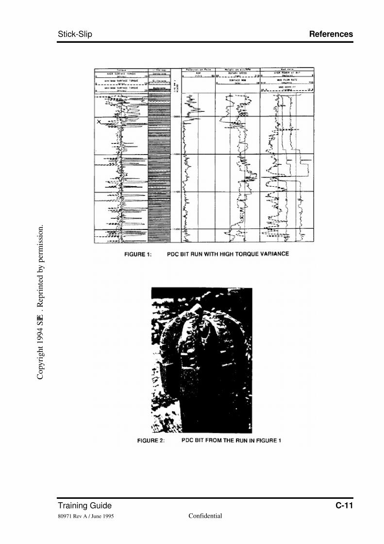
Figure 1 shows mud logging data from one such bit run, drilling with a 12.1/4" PDC bit ina compacted sand/shale sequence. High surface torque fluctuation early in the bit run is
shown by a wide departure between maximum and minimum surface torque, per foot
drilled.
Figure 2 shows the PDC bit after the run. The main wear mode is impact damage to the
cutters, with many having lost or damaged diamond layers. The mud logging data show
that rate of penetration (ROP) drops abruptly late in the period of highest torque variance,
due to the rapid development of cutter wear on the bit. Such an ROP drop is characteristic
of worn bits in these formations. The impact damage on the bit is thus related to the erratic
C o p y r i g h t 1 9 9 4 S P E
. R e p r i n t e d b y p e r m i s s i o n .
7/26/2019 Stick-slip Training Guide
http://slidepdf.com/reader/full/stick-slip-training-guide 28/54
C-4 Baker Hughes INTEQConfidential 80971 Rev A / June 1995
References Stick-Slip
torque. A possible explanation for both is the presence of torsional vibration. Brett (2)
describes such an association for PDC bits.
Compared to other runs with this bit type in these formations, this bit made around one
quarter of the expected footage. Those other bits, which exhibited less impact damage,
were run at higher rotary speeds.
Though the bit damage on this bit run, and the behaviour of surface torque are both
explicable in terms of torsional vibration, the data in figure 1 do not provide a definitive
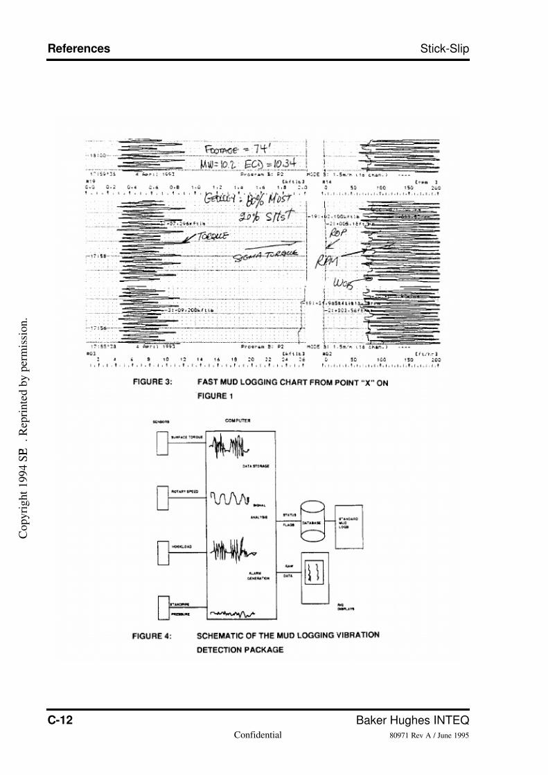
diagnosis of vibration type. However, during this investigation, high speed mud logging
chart recorders were in use to capture the full dynamic behaviour of surface torque. One of
the charts for this bit run is shown in f igure 3, corresponding to point "X" on figure 1. The
time scale is 24 seconds per horizontal division, and the two main variables shown are
surface torque and rotary speed. The regular, rythmic cycling in these two variables is
indicative of torsional vibration. Thus, an association between PDC bit damage and
torsional vibration is confirmed by this run.
A combination of mud logging data acquired at a sufficient frequency, together with a
high speed chart recorder, is all that is required to provide a detection capability for
torsional vibration. Given the costs associated with vibration-induced drilling problems,
development of a routine detection capability in harsh drilling environments was
considered appropriate as a first step in eradicating this type of vibration. Subsequent
work therefore concentrated on automating the detection capability, and combining it with
rigsite vibration suppression guidelines so that the rig team would respond to the vibration
once detected.
DETECTION AND SUPPRESSION OF TORSIONAL VIBRATION
An outline specification was developed for automated detection of torsional oscillations at
surface from mud logging systems. This involved measurement of the two main drilling
parameters (drive system torque, i.e. current, and rotary speed, i.e. voltage), plus hookload
and standpipe pressure, at a frequency sufficient to detect their full variation duringvibration. Some mud logging systems were already sampling sensors at sufficient data
rates. Next, the data were to be stored and displayed at the same rate, rather than being
reduced to time or depth-based averages for display. Thus, patterns of drilling parameter
behaviour could be displayed in full, and indications of vibration made visible. A
simplified schematic of the system is shown in figure 4.
Two major mud logging contractors have since developed and implemented this
capability on their standard mud logging systems. A third is currently developing the
package. Rig floor alarms have been added, together in one case with a signal detection
algorithm to discriminate torque oscillations due to torsional vibration from other patterns
of erratic torque, due for example to changes in weight on bit.
These systems therefore provide the capability to automatically detect and display
torsional vibration, and to alarm the rig crew to its occurrence.
It was recognised that to remove this type of vibration, the new detection capability would
have to be combined with rig guidelines on vibration suppression. A basic set of
guidelines, designed to be usable by the driller, were therefore developed. The guidelines
indicate practices that can stop torsional vibration once it has been detected. These
recommended practices drew heavily on indications from in house and published models
(2,10), together with observations from the field (12). They also described how the
C o p y r i g h t 1 9 9 4 S P E
. R e p r i n t e d b y p e r m i s s i o n .
7/26/2019 Stick-slip Training Guide
http://slidepdf.com/reader/full/stick-slip-training-guide 29/54
Training Guide C-580971 Rev A / June 1995 Confidential
Stick-Slip References
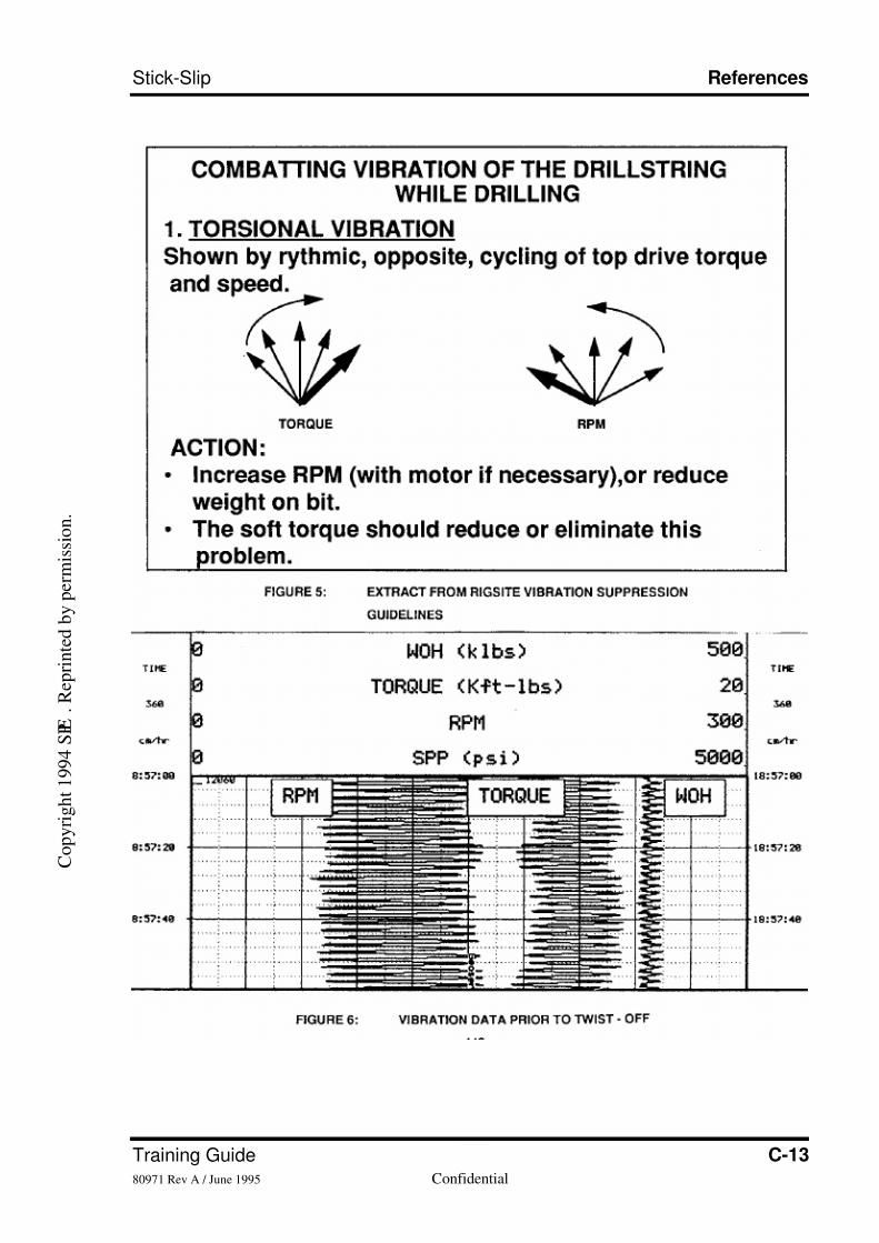
vibration would appear on drillers gauges. The part of these guidelines that deal with
torsional vibration is shown in figure 5.
The next section documents field experience from one year of drilling with the detection
package, and latterly the suppression guidelines, in place.
EXPERIENCE WITH VIBRATION DETECTION AND SUPPRESSION
The following examples are a small selection of the vibration incidents detected with the
mud logging systems. They have been chosen to illustrate the most important
characteristics of torsional vibration, and the effectiveness of various suppression
methods.
Example 1: Torsional vibration. twist-off
Figure 6 shows a small part of the printout from the vibration detection package, while
drilling at around 12060feet with a 12.1/4" anti-whirl bit, on a rotary BHA and 6.5/8"
drillpipe. A torque feedback system was in use. Mud type was oil base, and well
inclination 21 degrees. The time scale on the chart is 20 seconds per major division.
The data show the torque and rotary speed cycling that is characteristic of torsional
vibration. The amount of rotary speed cycling in response to the torque fluctuations is
exaggerated by the torque feedback system, which is designed to "soften" motor response
with modified speed control. The fluctuation in hookload ("WOH" - weight on hook), is a
result of rig power limitations rather than any coupled vibration. Similar behaviour is
often seen in pump speeds and therefore standpipe pressure ("SPP" in the f igures).
The frequency of the torque oscillations is around 0.49 Hertz. Using a model similar to
that described in reference 3, the lowest torsional resonance mode for this drillstring was
calculated at 0.29 Hertz. Either a higher mode of vibration had been excited, or only a
portion of the string was vibrating in its fundamental mode.
The torque feedback system was of a type that is tuned to suppress vibration at the lowesttorsional mode for the drillpipe size and length in use. The discrepancy between the
expected and actual frequency of torsional vibration explains the lack of successful
vibration suppression on this run. This particular torque feedback system requires manual
re-tuning in cases such as this.
After 6.5 hours of drilling, a twist-off occurred at the top of the near-bit stabiliser. The
parted connection was washed, probably indicating that the connection partially backed
off downhole, starting the washout. This mode of failure is compatible with the downhole
behaviour previously described as occurring during slip-stick.
Example 2: Torsional vibration. motor failure
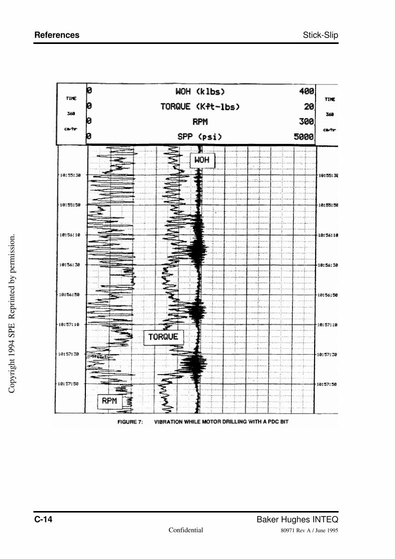
Figure 7 shows a realtime printout from the detectionpackage, while drilling at around
5200 feet, with a 9.1/2" steerable motor assembly and PDC bit in 17.1/2" hole. Mud type
was water base. Differential pressure across the motor was approximately 400 psi. Hole
inclination was 20 degrees.
Again, the characteristic cycling in torque and rotary speed is present, indicating torsional
vibration. The surface rotary speed in this case is, on average, low because bit speed is
provided by the motor.
In this interval, additional vibrational behaviour is present. Periods of high mean torque
(and consequent lower mean rotary speed) coincide with higher variance in hookload,
C o p y r i g h t 1 9 9 4 S P E
. R e p r i n t e d b y p e r m i s s i o n .
7/26/2019 Stick-slip Training Guide
http://slidepdf.com/reader/full/stick-slip-training-guide 30/54
C-6 Baker Hughes INTEQConfidential 80971 Rev A / June 1995
References Stick-Slip
indicating axial string motion (bouncing). The relationship of higher mean torque to high
hookload variance could indicate discrete bursts of whirl, possibly from the bit. A
coupling between whirl and axial type vibrations has previously been described to
facilitate whirl detection at surface, when well depth is shallow (13).
After 17 drilling hours, the motor failed, due to break up of the rubber stator. Afteranalysis, defects in stator composition and properties were ruled out as the cause. The
failure was then attributed by the motor supplier to excess differential pressure across the
motor. This in turn was revised when the vibration data was studied; the irregular torsional
and axial motion between the motor body and rotor, which would have accompanied the
vibration, is a more l ikely cause. Rotation of the rotor would be anything but smooth in the
presence of these forms of vibration.
This was a good example of how a drilling operation may not realise that vibration is a
cause of a failure until direct measurements of vibration are actually made available.
The PDC bit also exhibited uneven wear, and cutter breakage (graded 6-2-BT).
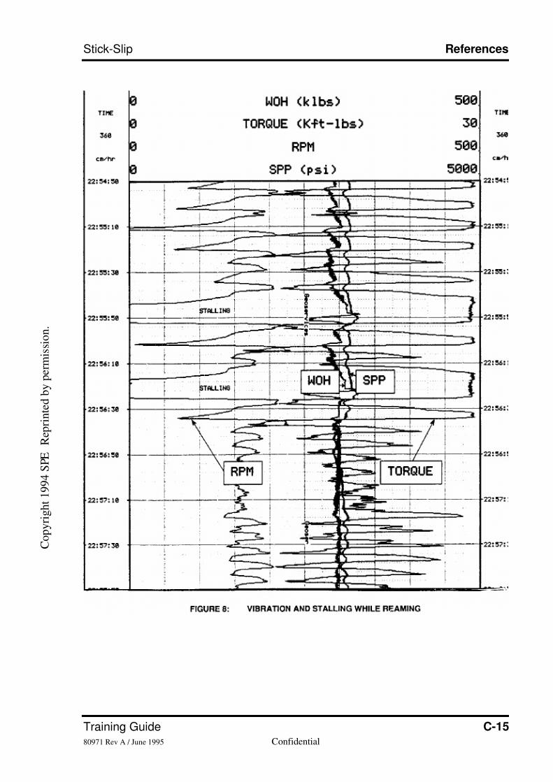
Example 3: Torsional vibration and stalling while reaming
Figure 8 shows the detection package printout from an interval of reaming at 13025 feet in
8.1/2" hole, with a PDC bit and two roller reamers.
The data show large scale cycling in surface torque and rotary speed; peak to peak torque
values are around 15 Kft.lbs. No torque feedback system was in use on this run.
The data show two intervals where the top drive stalled, as the torque oscillations peaked
at a level unsustainable for the top drive motor. The string was then picked up and the
motor re-started, before reaming could commence.
Repeated stalling is a common consequence of heavy torsional vibration; the maximum
torque values are obviously raised by the dynamic component of torque, to the point
where stalling is more likely. In the authors' experience, rig reports of stalling problems
often indicate torsional vibration to be present, though without the direct measurements
shown here, rig teams often do not realise that torsional vibration is occurring andtherefore do not report the problem in those terms.
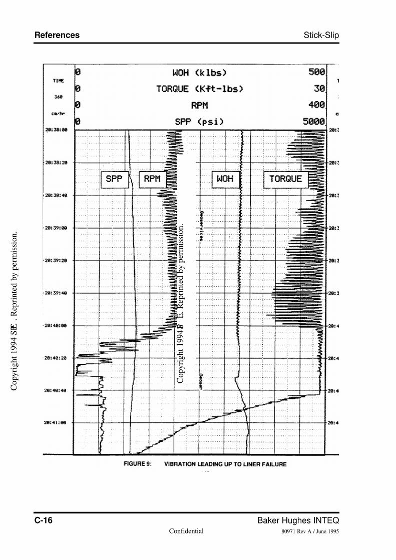
Example 4: Liner failure during torsional vibration
Figure 9 shows a vibration chart from a part of a liner running operation. The 7.5/8"
diameter liner was being run into 8.1/2" hole, below a 9.5/8" casing string.
High torque and an inability to slide without rotation required the use of high rotary speed
to work the liner down. Unfortunately, rotation of the liner, as is obvious from the chart,
was accompanied by torsional vibration. After 25-30 minutes of this behaviour, a
connection in the liner failed, leaving 1000 feet of l iner in the well. The point of failure is
marked by the abrupt drop in rotary torque near the end of the chart.
The part of the liner left downhole was being rotated in a section containing two sharp dog
legs. The combination of cyclic bending, and the repeated twisting from the torsional
oscillations, is the most likely cause of the connection failure.
The occurrence of torsional vibration while running a tubular string without a bit or
stabilisers confirms the hypothesis that differences between static and dynamic frictional
torque between a drillstring and the borehole wall can set up torsional vibration (11).
C o p y r i g h t 1 9 9 4 S P E
. R e p r i n t e d b y p e r m i s s i o n .
7/26/2019 Stick-slip Training Guide
http://slidepdf.com/reader/full/stick-slip-training-guide 31/54
Training Guide C-780971 Rev A / June 1995 Confidential
Stick-Slip References
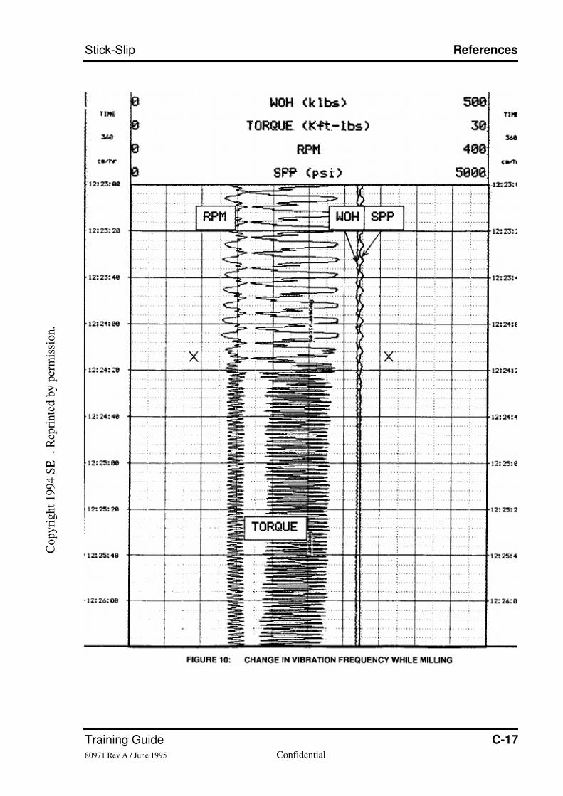
Example 5: Variable frequency of torsional vibration
Figure 10 shows a vibration detection chart from a period of milling, with a 6" flat bottom
mill at a 7" liner shoe. Measured depth was 16951 feet. The chart time scale is again 20
seconds per major division.
The torque and rotary speed again show the cyclicity characteristic of torsional vibration.
Early in the operation and on the chart, the frequency of the vibration is around 0.15 Hertz.
At point "X" on the chart, the frequency of the torsional vibration changes to around 0.6
Hertz, with no change in applied parameters. This changing vibration frequency has been
observed on a number of occasions now that torsional vibration is being routinely
monitored.
Attempts were being made during this operation to remove the torsional vibration with a
torque feedback system. This can be seen from the chart as having been unsuccesful, not
least due to the changes in the period of torsional oscillations. An ability to quickly re-tune
to a new vibration frequency is obviously a pre-requisite for an effective feedback system
under these conditions.
After approximately 14 hours of milling, with torsional vibration persistently present, adrill collar connection twisted off five collars above the mill. These drill collars had
accumulated 145 hours since the previous inspection, and were new at the start of this
milling operation (this was the third milling run). Obviously 145 hours of drilling under
smooth conditions is less detrimental to connection fatigue life than operating under the
conditions shown on the chart. This suggests that inspection frequency should take
torsional vibration into account.
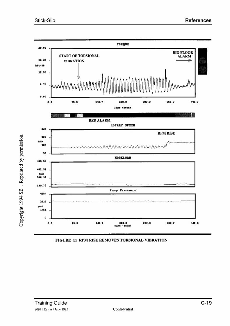
Example 6: Suppression of torsional vibration
Figure11 shows the vibration detection display window from another mud logging system.
As before, torque, rotary speed, hookload and standpipe pressure data are displayed.
Below and to the right of the upper (torque)section is the alarm status, which goes from
green to red when torsional vibration is detected.
In this example, while drilling cement with an 8.1/2" PDC bit at 18500 feet, torque cycling
begins and progressively builds in amplitude. The detection system responds with a
change to a red alarm, which is displayed in "traffic light"form next to the driller. The
driller has then consulted the vibration suppression guidelines and raised the rotary speed
from 100 to around 140 RPM. Toward the right end of the window, this is seen to
eliminate the torsional oscillations.
The use of higher rotary speed is recommended as the first method to eliminate torsional
vibration since this does not cause any reduction in penetration rate. Use of lower weight
on bit, which has been found to be equally effective, usually does reduce penetration rate.
The disappearance of torsional oscillations above a certain rotary speed is fully in line
with model predictions (2,10), and field observations (2,12).in the authors' experience,
while drilling formations with PDC bits, that critical rotary speed usually lies in the range150-220 RPM. The elimination of torsional vibration above these speeds explains the
disappearance of torque problems and bit impact damage in some applications when PDC
bits are run on downhole motors or turbines. Such practices are, for example, common in
the hard Cretaceous limestones of the Central North Sea.
It is worthy of note that if whirl was the major cause of PDC bit impact damage in harder
formations, use of higher bit speeds should worsen bit damage (1). In the authors'
experience, use of higher bit speeds appears to improve PDC bit performance more often
than it makes it worse. This is because the extra life that is afforded by eliminating
C o p y r i g h t 1 9 9 4 S P E
. R e p r i n t e d b y p e r m i s s i o n .

7/26/2019 Stick-slip Training Guide
http://slidepdf.com/reader/full/stick-slip-training-guide 32/54
C-8 Baker Hughes INTEQConfidential 80971 Rev A / June 1995
References Stick-Slip
torsional vibration more than offsets the increase in abrasive wear that accompanies
higher bit speeds.
IMPLICATIONS FOR TORQUE FEEDBACK SYSTEMS
Torque feedback systems provide modified electronic speed control to the surface motor,
so that an increase in surface torque (motor current) is countered by a decrease in motor
speed (motor voltage). This increases damping provided by the motor and helps to prevent
initial torsional oscillations building into full slip-stick. As a result of the lower surface
impedance, torsional oscillations are absorbed at surface rather than reflected back
downhole (3,6).
The field experience reported here has included a number of observations pertinent to the
design of these feedback systems. First, the frequency of torsional vibration may not be
that of the lowest torsional resonance mode for the full length of drillpipe, and that
frequency may not remain constant. For system tuning purposes, modelling of the
drillstring to determine the expected frequency of vibration (the lowest torsional mode) is
thus less satisfactory than measuring the predominant frequency directly. Second,torsional vibration occurs over a wide range of frequencies, so that a feedback system
must be effective over as wide a frequency range as possible, with minimal re-tuning
required as the frequency changes. This implies that the characteristics of the system be
such that the feedback setting is relatively insensitive to vibration frequency. Sananikone
et al (6) provide a comparison of the expected frequency range over which different
system designs should be effective. Finally, the variable nature of torsional vibration
frequency, as illustrated in example 5, means that if the feedback system requires manual
re-tuning, the interface through which tuning is performed should be one that is simple
and robust enough forrigsite use. A keyboard interface is, for example, more appropriate
than bare, intricate circuitry.
EFFECTS ON DRILLING PERFORMANCE
The effort to eradicate torsional vibration from drilling operations was initially focussed
on a major development and appraisal drilling project in Colombia. Within that project,
PDC bit life in particular was being detrimentally affected by torsional vibration.
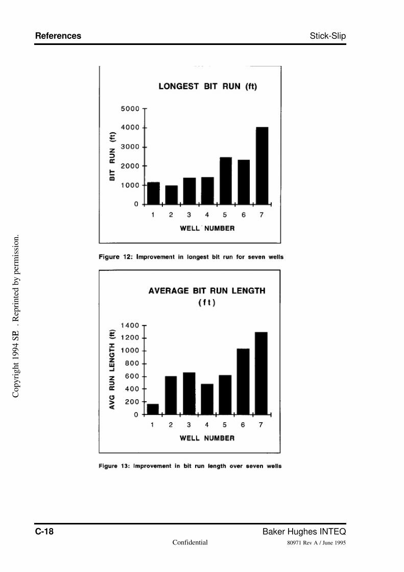
Figures 12 and 13 show, for a group of geographically adjacent wells in this development,
trends in bit life for 17.1/2" sections. The figures indicate the longest bit run, and the
average bit run length, in feet. Full implementation of the detection and suppression
practices was made on the sixth and seventh wells. Considerable improvement in bit life
andrun length has resulted. This was despite, in well number 1 and from well number 4
onwards, the section end depth being extended to include a harder, more sandy interval.
These bit life improvements, the bulk of which are due to vibration suppression, have
contributed to a reduction in bit-dependent cost per foot for these 17.1/2" sections from aweighted average of $316/foot for the first five wells, to $181/foot for the last two. This
has produced savings of approximately $1.2 million on each of the last two 17.1/2"
sections. This excludes savings due to reduced drillstring failures.
Efforts are now being made to extend these detection capabilities and vibration
suppression practices to other areas where drilling conditions are harsh.
C o p y r i g h t 1 9 9 4 S P E
. R e p r i n t e d b y p e r m i s s i o n .
7/26/2019 Stick-slip Training Guide
http://slidepdf.com/reader/full/stick-slip-training-guide 33/54
Training Guide C-980971 Rev A / June 1995 Confidential
Stick-Slip References
DRILLING IN HARSH ENVIRONMENTS
This work has shown that torsional vibration causes drillstring failures and reduced PDC
bit life. In areas where drilling conditions are rough, the costs associated with these
problems can be significant. It is also clear that this form of vibration can be detected and
suppressed at low cost and with minimal technical complexity.
For drilling contractors and operators drilling in harsh environments, it is thus highly cost
effective to monitor for torsional vibration, and to modify conventional drilling practices
to suppress it.
For mud logging contractors, the ability to detect and display torsional vibration provides
a powerful means to contribute to improvements in bit life and drillstring failure
avoidance. If a torque feedback system is in use, a permanent record of its efficiency will
be provided by the vibration detection package.
For drill bit suppliers, practices for running PDC bits, and post-run analyses, should
acknowledge the significant contribution that torsional vibration can make to bit life. Its
presence should be routinely checked for in failure investigations.
CONCLUSIONS
1. The new vibration detection capability described here has shown that torsional vibration
is a major cause of drillstring failures and reduced PDC bit life in areas where drilling
conditions are harsh.
2. With improved vibration detection, torque feedback, and modified drilling practices,
torsional vibration can be eradicated. This yields substantial benefit in reduced drilling
costs.
3. The effectiveness of torque feedback systems for suppression of torsional vibration
depends heavily on their ability to respond to changing vibration frequency, and to operate
over a wide range of frequencies. Not all current systems are satisfactory by these criteria.4.Torsional vibration is not confined to drilling with rotary bottomhole assemblies. It has
also been detected while drilling with downhole motors in rotary mode, reaming, drilling
cement, milling casing shoes, and rotating liners. It is a persistent problem whenever
variable torque downhole is applied to a torsionally umber string of tubulars.
5. Systematic monitoring of vibration, and correlation with drilling problems, helps shift
practices for dealing with drillstring failures from those based totally on equipment
integrity and inspection, to include smoothing out drilling conditions downhole. This is
more realistic given that downhole components of any quality and age will fail more
rapidly when exposed to persistent vibration.
ACKNOWLEDGEMENTS
The authors wish to thank BP Exploration, Total C.F.P., Triton Energy Corporation and
Ecopetrol for permission to publish this paper. Thanks are also due to those field and
technical support personnel within Geoservices and Baker Hughes Inteq who have
assisted with system development, data collection, and vibration suppression.
C o p y r i g h t 1 9 9 4 S P E
. R e p r i n t e d b y p e r m i s s i o n .
7/26/2019 Stick-slip Training Guide
http://slidepdf.com/reader/full/stick-slip-training-guide 34/54
C-10 Baker Hughes INTEQConfidential 80971 Rev A / June 1995
References Stick-Slip
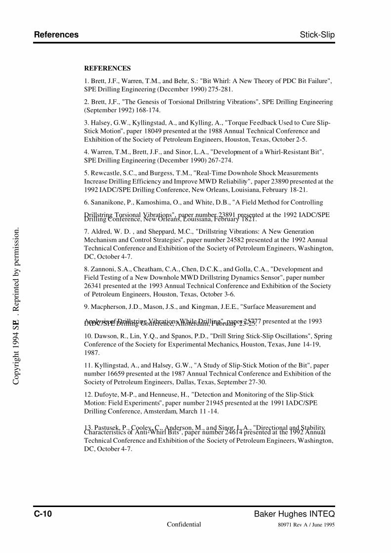
REFERENCES
1. Brett, J.F., Warren, T.M., and Behr, S.: "Bit Whirl: A New Theory of PDC Bit Failure",
SPE Drilling Engineering (December 1990) 275-281.
2. Brett, J,F., "The Genesis of Torsional Drillstring Vibrations", SPE Drilling Engineering
(September 1992) 168-174.
3. Halsey, G.W., Kyllingstad, A., and Kylling, A., "Torque Feedback Used to Cure Slip-
Stick Motion", paper 18049 presented at the 1988 Annual Technical Conference and
Exhibition of the Society of Petroleum Engineers, Houston, Texas, October 2-5.
4. Warren, T.M., Brett, J.F., and Sinor, L.A., "Development of a Whirl-Resistant Bit",
SPE Drilling Engineering (December 1990) 267-274.
5. Rewcastle, S.C., and Burgess, T.M., "Real-Time Downhole Shock Measurements
Increase Drilling Efficiency and Improve MWD Reliability", paper 23890 presented at the
1992 IADC/SPE Drilling Conference, New Orleans, Louisiana, February 18-21.
6. Sananikone, P., Kamoshima, O., and White, D.B., "A Field Method for Controlling
Drillstring Torsional Vibrations", paper number 23891 presented at the 1992 IADC/SPEDrilling Conference, New Orleans, Louisiana, February 1821.
7. Aldred, W. D. , and Sheppard, M.C., "Drillstring Vibrations: A New Generation
Mechanism and Control Strategies", paper number 24582 presented at the 1992 Annual
Technical Conference and Exhibition of the Society of Petroleum Engineers, Washington,
DC, October 4-7.
8. Zannoni, S.A., Cheatham, C.A., Chen, D.C.K., and Golla, C.A., "Development and
Field Testing of a New Downhole MWD Drillstring Dynamics Sensor", paper number
26341 presented at the 1993 Annual Technical Conference and Exhibition of the Society
of Petroleum Engineers, Houston, Texas, October 3-6.
9. Macpherson, J.D., Mason, J.S., and Kingman, J.E.E., "Surface Measurement and
Analysis of Drillstring Vibrations While Drilling", paper 25777 presented at the 1993IADC/SPE Drilling Conference, Amsterdam, February 23-25.
10. Dawson, R., Lin, Y.Q., and Spanos, P.D., "Drill String Stick-Slip Oscillations", Spring
Conference of the Society for Experimental Mechanics, Houston, Texas, June 14-19,
1987.
11. Kyllingstad, A., and Halsey, G.W., "A Study of Slip-Stick Motion of the Bit", paper
number 16659 presented at the 1987 Annual Technical Conference and Exhibition of the
Society of Petroleum Engineers, Dallas, Texas, September 27-30.
12. Dufoyte, M-P., and Henneuse, H., "Detection and Monitoring of the Slip-Stick
Motion: Field Experiments", paper number 21945 presented at the 1991 IADC/SPE
Drilling Conference, Amsterdam, March 11 -14.
13. Pastusek, P., Cooley, C., Anderson, M., and Sinor, L.A., "Directional and StabilityCharacteristics of Anti-Whirl Bits", paper number 24614 presented at the 1992 Annual
Technical Conference and Exhibition of the Society of Petroleum Engineers, Washington,
DC, October 4-7.
C o p y r i g h t 1 9 9 4 S P E
. R e p r i n t e d b y p e r m i s s i o n .
7/26/2019 Stick-slip Training Guide
http://slidepdf.com/reader/full/stick-slip-training-guide 35/54
Training Guide C-1180971 Rev A / June 1995 Confidential
Stick-Slip References
C o p y r i g h t 1 9 9 4 S P E
. R e p r i n t e d b y p e r m i s s i o n .
7/26/2019 Stick-slip Training Guide
http://slidepdf.com/reader/full/stick-slip-training-guide 36/54
C-12 Baker Hughes INTEQConfidential 80971 Rev A / June 1995
References Stick-Slip
C o p y r i g h t 1 9 9 4 S P E
. R e p r i n t e d b y p e r m i s s i o n .
7/26/2019 Stick-slip Training Guide
http://slidepdf.com/reader/full/stick-slip-training-guide 37/54
Training Guide C-1380971 Rev A / June 1995 Confidential
Stick-Slip References
C o p y r i g h t 1 9 9 4 S P E .
R e p r i n t e d b y p e r m i s s i o n .
7/26/2019 Stick-slip Training Guide
http://slidepdf.com/reader/full/stick-slip-training-guide 38/54
C-14 Baker Hughes INTEQConfidential 80971 Rev A / June 1995
References Stick-Slip
C o p y r i g h t 1 9 9 4 S P E .
R e p r i n t e d b y p e r m i s s i o n .
7/26/2019 Stick-slip Training Guide
http://slidepdf.com/reader/full/stick-slip-training-guide 39/54
Training Guide C-1580971 Rev A / June 1995 Confidential
Stick-Slip References
C o p y r i g h t 1 9 9 4 S P E .
R e p r i n t e d b y p e r m i s s i o n .
7/26/2019 Stick-slip Training Guide
http://slidepdf.com/reader/full/stick-slip-training-guide 40/54
C-16 Baker Hughes INTEQConfidential 80971 Rev A / June 1995
References Stick-Slip
C o p y r i g h t 1 9 9 4 S P
E .
R e p r i n t e d b y p e r m i s s i o n .
C o p y r i g h t 1 9 9 4 S P E
. R e p r i n t e d b y p e r m i s s i o n .
7/26/2019 Stick-slip Training Guide
http://slidepdf.com/reader/full/stick-slip-training-guide 41/54
Training Guide C-1780971 Rev A / June 1995 Confidential
Stick-Slip References
C o p y r i g h t 1 9 9 4 S P E
. R e p r i n t e d b y p e r m i s s i o n .
7/26/2019 Stick-slip Training Guide
http://slidepdf.com/reader/full/stick-slip-training-guide 42/54
C-18 Baker Hughes INTEQConfidential 80971 Rev A / June 1995
References Stick-Slip
C o p y r i g h t 1 9 9 4 S P E
. R e p r i n t e d b y p e r m i s s i o n .
7/26/2019 Stick-slip Training Guide
http://slidepdf.com/reader/full/stick-slip-training-guide 43/54
Training Guide C-1980971 Rev A / June 1995 Confidential
Stick-Slip References
C o p y r i g h t 1 9 9 4 S P E
. R e p r i n t e d b y p e r m i s s i o n .

7/26/2019 Stick-slip Training Guide
http://slidepdf.com/reader/full/stick-slip-training-guide 44/54
C-20 Baker Hughes INTEQConfidential 80971 Rev A / June 1995
References Stick-Slip
•Notes•
7/26/2019 Stick-slip Training Guide
http://slidepdf.com/reader/full/stick-slip-training-guide 45/54
Training Guide D-180971 Rev A / June 1995 Confidential
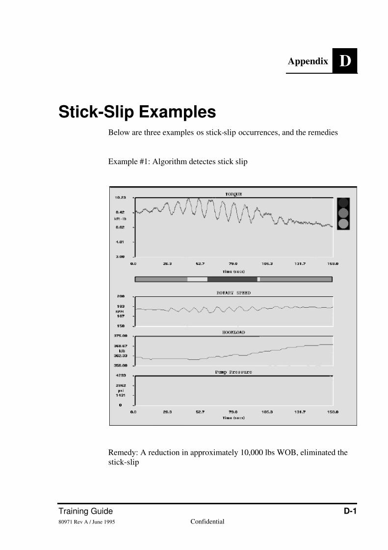
Appendix D
Stick-Slip ExamplesBelow are three examples os stick-slip occurrences, and the remedies
Example #1: Algorithm detectes stick slip
Remedy: A reduction in approximately 10,000 lbs WOB, eliminated thestick-slip
7/26/2019 Stick-slip Training Guide
http://slidepdf.com/reader/full/stick-slip-training-guide 46/54
D-2 Baker Hughes INTEQConfidential 80971 Rev A / June 1995
Stick-Slip Examples Stick-Slip
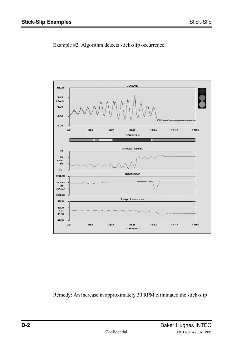
Example #2: Algorithm detects stick-slip occurrence
Remedy: An increase in approximately 30 RPM eliminated the stick-slip
7/26/2019 Stick-slip Training Guide
http://slidepdf.com/reader/full/stick-slip-training-guide 47/54
Training Guide D-380971 Rev A / June 1995 Confidential
Stick-Slip Stick-Slip Examples
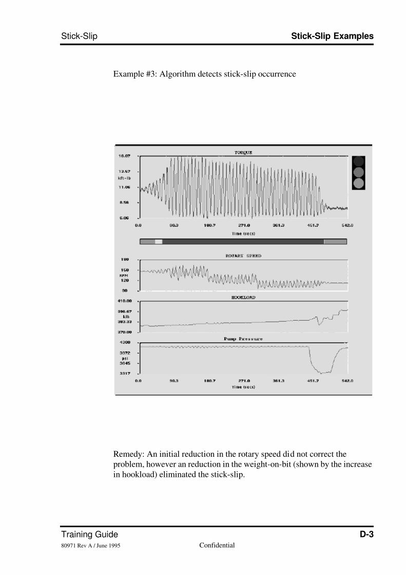
Example #3: Algorithm detects stick-slip occurrence
Remedy: An initial reduction in the rotary speed did not correct theproblem, however an reduction in the weight-on-bit (shown by the increasein hookload) eliminated the stick-slip.
7/26/2019 Stick-slip Training Guide
http://slidepdf.com/reader/full/stick-slip-training-guide 48/54
D-4 Baker Hughes INTEQConfidential 80971 Rev A / June 1995
Stick-Slip Examples Stick-Slip
•Notes•

7/26/2019 Stick-slip Training Guide
http://slidepdf.com/reader/full/stick-slip-training-guide 49/54
Training Guide D-580971 Rev A / June 1995 Confidential
Stick-Slip Stick-Slip Examples

7/26/2019 Stick-slip Training Guide
http://slidepdf.com/reader/full/stick-slip-training-guide 50/54
D-6 Baker Hughes INTEQConfidential 80971 Rev A / June 1995
Stick-Slip Examples Stick-Slip
7/26/2019 Stick-slip Training Guide
http://slidepdf.com/reader/full/stick-slip-training-guide 51/54
Training Guide E-180971 Rev A / June 1995 Confidential
Appendix E
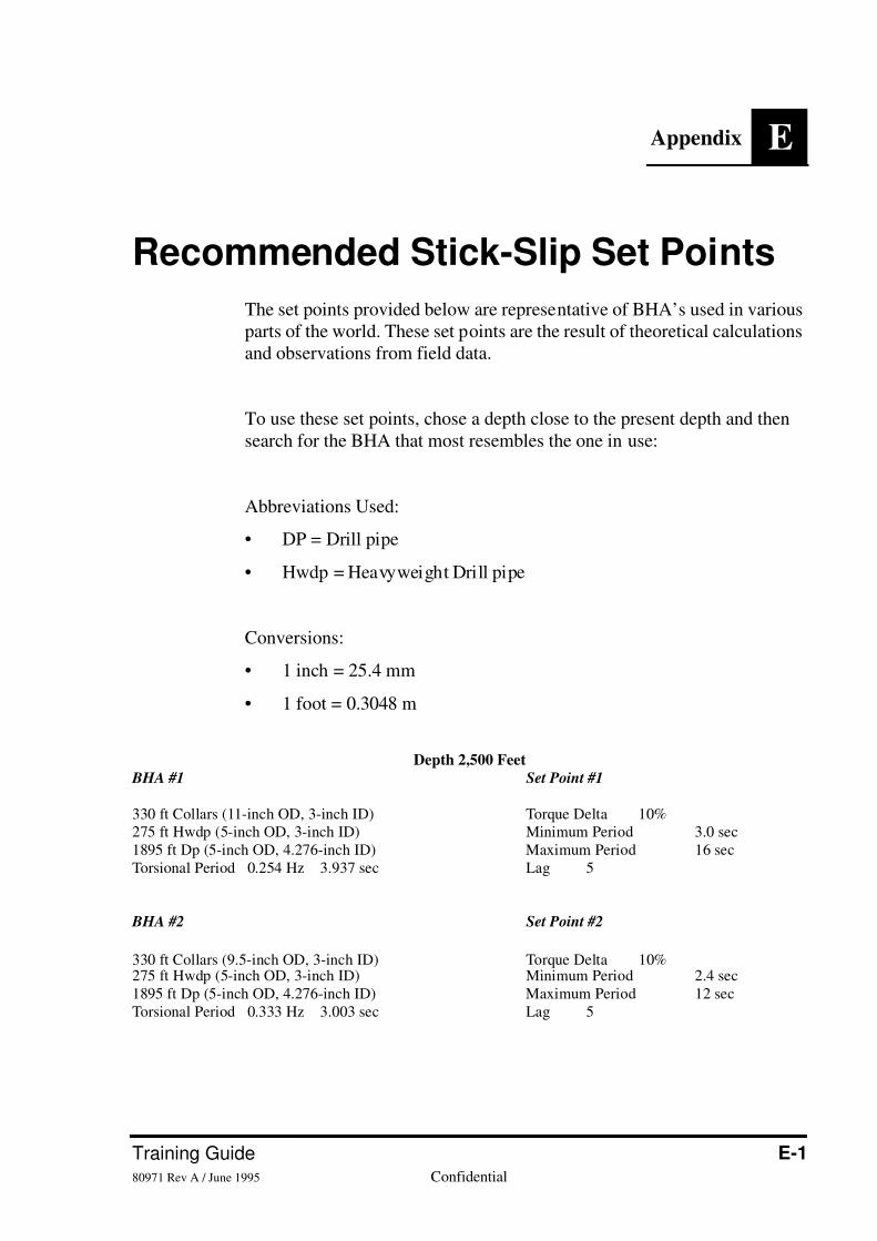
Recommended Stick-Slip Set Points
The set points provided below are representative of BHA’s used in variousparts of the world. These set points are the result of theoretical calculationsand observations from field data.
To use these set points, chose a depth close to the present depth and thensearch for the BHA that most resembles the one in use:
Abbreviations Used:
• DP = Drill pipe
• Hwdp = Heavyweight Drill pipe
Conversions:
• 1 inch = 25.4 mm
• 1 foot = 0.3048 m
Depth 2,500 Feet
BHA #1 Set Point #1
330 ft Collars (11-inch OD, 3-inch ID) Torque Delta 10%275 ft Hwdp (5-inch OD, 3-inch ID) Minimum Period 3.0 sec1895 ft Dp (5-inch OD, 4.276-inch ID) Maximum Period 16 secTorsional Period 0.254 Hz 3.937 sec Lag 5
BHA #2 Set Point #2
330 ft Collars (9.5-inch OD, 3-inch ID) Torque Delta 10%275 ft Hwdp (5-inch OD, 3-inch ID) Minimum Period 2.4 sec1895 ft Dp (5-inch OD, 4.276-inch ID) Maximum Period 12 secTorsional Period 0.333 Hz 3.003 sec Lag 5
7/26/2019 Stick-slip Training Guide
http://slidepdf.com/reader/full/stick-slip-training-guide 52/54
E-2 Baker Hughes INTEQConfidential 80971 Rev A / June 1995
Recommended Stick-Slip Set Points Stick-Slip
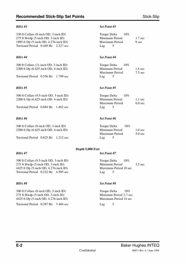
BHA #3 Set Point #3
330 ft Collars (8-inch OD, 3-inch ID) Torque Delta 10%275 ft Hwdp (5-inch OD, 3-inch ID) Minimum Period 1.7 sec1895 ft Dp (5-inch OD, 4.276-inch ID) Maximum Period 9 secTorsional Period 0.449 Hz 2.227 sec Lag 5
BHA #4 Set Point #4
300 ft Collars (11-inch OD, 3-inch ID) Torque Delta 10%2200 ft Dp (6.625-inch OD, 4-inch ID) Minimum Period 1.4 sec
Maximum Period 7.5 secTorsional Period 0.556 Hz 1.799 sec Lag 5
BHA #5 Set Point #5
300 ft Collars (9.5-inch OD, 3-inch ID) Torque Delta 10%2200 ft Dp (6.625-inch OD, 4-inch ID) Minimum Period 1.1 sec
Maximum Period 6.0 secTorsional Period 0.684 Hz 1.462 sec Lag 5
BHA #6 Set Point #6
300 ft Collars (8-inch OD, 3-inch ID) Torque Delta 10%2200 ft Dp (6.625-inch OD, 4-inch ID) Minimum Period 1.0 sec
Maximum Period 5.0 secTorsional Period 0.825 Hz 1.212 sec Lag 5
Depth 5,000 Feet
BHA #7 Set Point #7
300 ft Collars (9.5-inch OD, 3-inch ID) Torque Delta 10%275 ft Hwdp (5-inch OD, 3-inch ID) Minimum Period 3.5 sec4425 ft Dp (5-inch OD, 4.276-inch ID) Maximum Period 18 secTorsional Period 0.222 Hz 4.505 sec Lag 5
BHA #8 Set Point #8
300 ft Collars (8-inch OD, 3-inch ID) Torque Delta 10%275 ft Hwdp (5-inch OD, 3-inch ID) Minimum Period 2.7 sec4425 ft Dp (5-inch OD, 4.276-inch ID) Maximum Period 14 sec
Torsional Period 0.287 Hz 3.484 sec Lag 5
7/26/2019 Stick-slip Training Guide
http://slidepdf.com/reader/full/stick-slip-training-guide 53/54
Training Guide E-380971 Rev A / June 1995 Confidential
Stick-Slip Recommended Stick-Slip Set Points
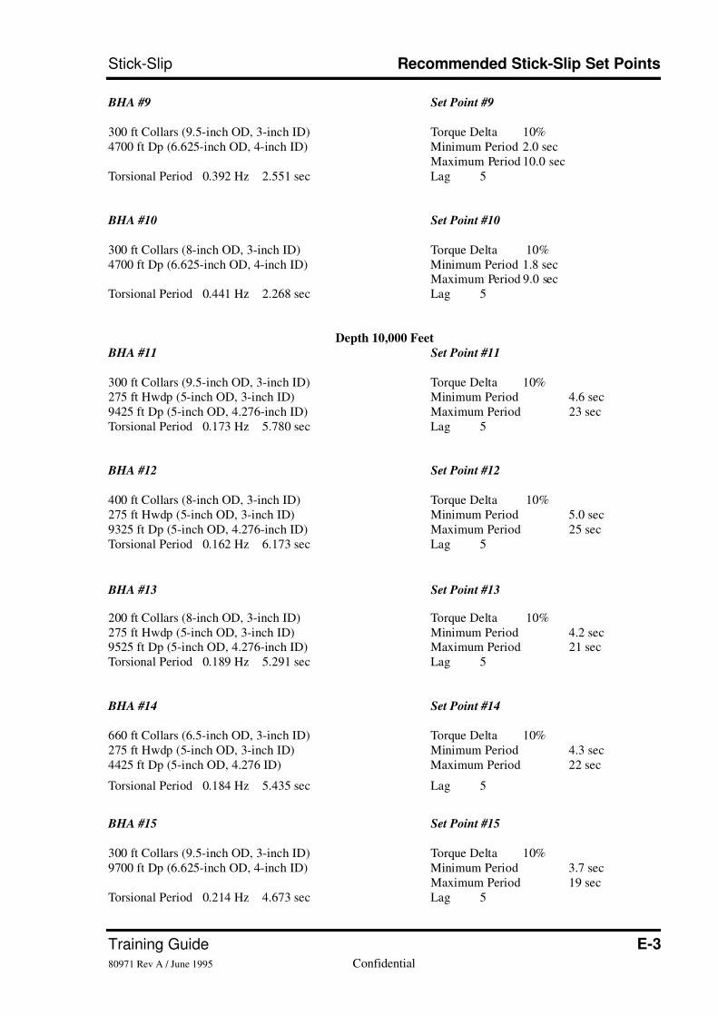
BHA #9 Set Point #9
300 ft Collars (9.5-inch OD, 3-inch ID) Torque Delta 10%4700 ft Dp (6.625-inch OD, 4-inch ID) Minimum Period 2.0 sec
Maximum Period 10.0 secTorsional Period 0.392 Hz 2.551 sec Lag 5
BHA #10 Set Point #10
300 ft Collars (8-inch OD, 3-inch ID) Torque Delta 10%4700 ft Dp (6.625-inch OD, 4-inch ID) Minimum Period 1.8 sec
Maximum Period 9.0 secTorsional Period 0.441 Hz 2.268 sec Lag 5
Depth 10,000 Feet
BHA #11 Set Point #11
300 ft Collars (9.5-inch OD, 3-inch ID) Torque Delta 10%275 ft Hwdp (5-inch OD, 3-inch ID) Minimum Period 4.6 sec9425 ft Dp (5-inch OD, 4.276-inch ID) Maximum Period 23 secTorsional Period 0.173 Hz 5.780 sec Lag 5
BHA #12 Set Point #12
400 ft Collars (8-inch OD, 3-inch ID) Torque Delta 10%275 ft Hwdp (5-inch OD, 3-inch ID) Minimum Period 5.0 sec9325 ft Dp (5-inch OD, 4.276-inch ID) Maximum Period 25 secTorsional Period 0.162 Hz 6.173 sec Lag 5
BHA #13 Set Point #13
200 ft Collars (8-inch OD, 3-inch ID) Torque Delta 10%275 ft Hwdp (5-inch OD, 3-inch ID) Minimum Period 4.2 sec9525 ft Dp (5-inch OD, 4.276-inch ID) Maximum Period 21 secTorsional Period 0.189 Hz 5.291 sec Lag 5
BHA #14 Set Point #14
660 ft Collars (6.5-inch OD, 3-inch ID) Torque Delta 10%275 ft Hwdp (5-inch OD, 3-inch ID) Minimum Period 4.3 sec4425 ft Dp (5-inch OD, 4.276 ID) Maximum Period 22 sec
Torsional Period 0.184 Hz 5.435 sec Lag 5
BHA #15 Set Point #15
300 ft Collars (9.5-inch OD, 3-inch ID) Torque Delta 10%9700 ft Dp (6.625-inch OD, 4-inch ID) Minimum Period 3.7 sec
Maximum Period 19 secTorsional Period 0.214 Hz 4.673 sec Lag 5
7/26/2019 Stick-slip Training Guide
http://slidepdf.com/reader/full/stick-slip-training-guide 54/54
Recommended Stick-Slip Set Points Stick-Slip
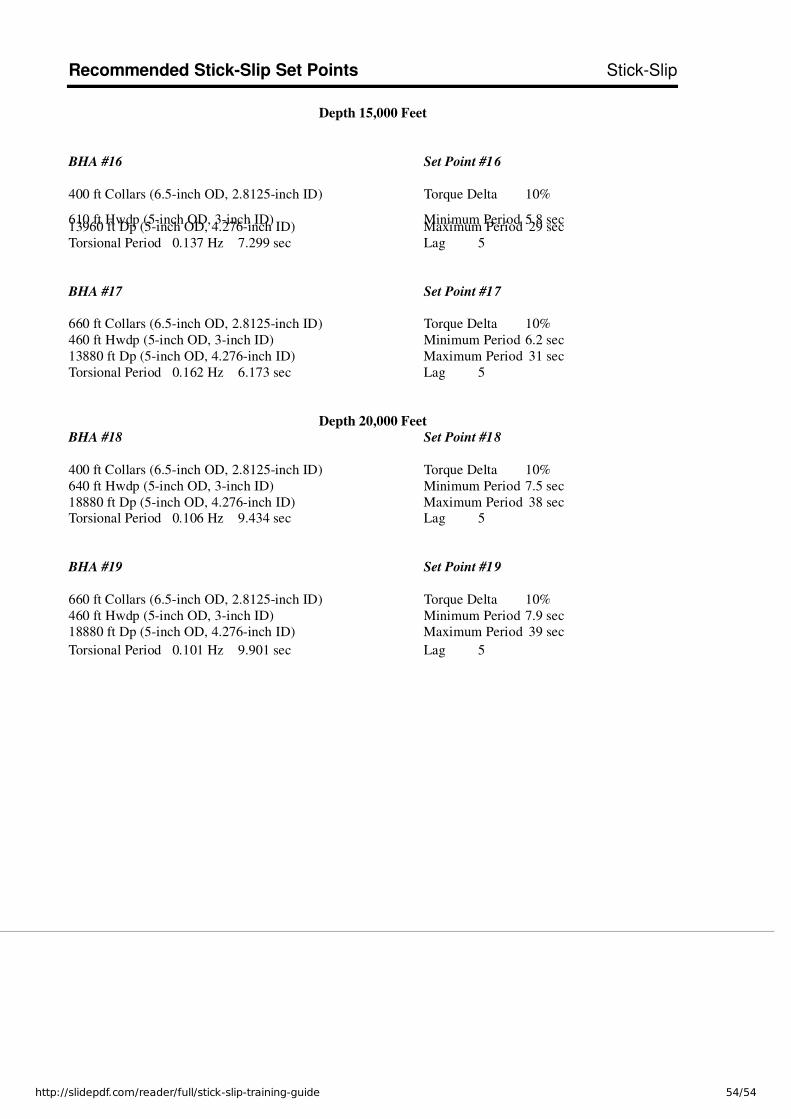
Depth 15,000 Feet
BHA #16 Set Point #16
400 ft Collars (6.5-inch OD, 2.8125-inch ID) Torque Delta 10%
610 ft Hwdp (5-inch OD, 3-inch ID) Minimum Period 5.8 sec13960 ft Dp (5-inch OD, 4.276-inch ID) Maximum Period 29 secTorsional Period 0.137 Hz 7.299 sec Lag 5
BHA #17 Set Point #17
660 ft Collars (6.5-inch OD, 2.8125-inch ID) Torque Delta 10%460 ft Hwdp (5-inch OD, 3-inch ID) Minimum Period 6.2 sec13880 ft Dp (5-inch OD, 4.276-inch ID) Maximum Period 31 secTorsional Period 0.162 Hz 6.173 sec Lag 5
Depth 20,000 Feet
BHA #18 Set Point #18
400 ft Collars (6.5-inch OD, 2.8125-inch ID) Torque Delta 10%640 ft Hwdp (5-inch OD, 3-inch ID) Minimum Period 7.5 sec18880 ft Dp (5-inch OD, 4.276-inch ID) Maximum Period 38 secTorsional Period 0.106 Hz 9.434 sec Lag 5
BHA #19 Set Point #19
660 ft Collars (6.5-inch OD, 2.8125-inch ID) Torque Delta 10%460 ft Hwdp (5-inch OD, 3-inch ID) Minimum Period 7.9 sec18880 ft Dp (5-inch OD, 4.276-inch ID) Maximum Period 39 sec
Torsional Period 0.101 Hz 9.901 sec Lag 5