stereo vision in smart camera networks
TRANSCRIPT

5
Stereo Vision in Smart Camera Networks
Stephan Hengstler Department of Electrical Engineering, Stanford University
United States of America
1. Introduction
Stereo vision inherently comes with high computational complexity, which previously limited its deployment to high-performance, centralized imaging systems. But recent advances in embedded systems and algorithm design have paved the way for its adoption for and migration into smart camera networks, which notoriously suffer from limited processing and energy resources. Such networks consist of a collection of relatively low-cost smart camera motes, which—in their simplest form—integrate a microcontroller, an image sensor, and a radio into a single, embedded unit capable of sensing, computation, and wireless communication. When deployed in an in- or outdoor environment, they form ad-hoc or mesh networks that can perform a wide range of applications. Their application areas range from ambient intelligence, building automation, elderly care, autonomous surveillance, and traffic control to smart homes. The underlying network tasks include object localization, target tracking, occupancy sensing, object detection and classification. Stereo vision can bring increased performance and robustness to several of these tasks possibly even at overall reductions in energy consumption and prolonged network lifetime. This chapter will provide a brief description of the building blocks, characteristics, limitations and applications of smart camera networks. We will then present a discussion of their requirements and constraints with respect to stereo vision paying special attention to differences to conventional stereo vision systems. The main issue arises from the high data rate, which image sensors particularly in a stereoscopic configuration generate. Conventional centralized computing systems can easily handle such rates. But for smart camera networks, their resource constraints pose a serious challenge to effective acquisition and processing of this high-rate data. Two possible approaches to address this problem have emerged in recent publications: one suggests the design of a custom image processor whereas the other solution proposes utilization of off-the-shelf, general-purpose microprocessors in conjunction with resolution-scaled image sensors. Our discussion focuses on these two state-of-the-art stereo architectures. NXP's WiCa mote is the primary example deploying a dedicated image processor, while Stanford's MeshEye mote pioneered the idea of resolution-scaled stereo vision. More specifically, the WiCa mote deploys an application-specific image processor based on a vector single-instruction, multiple-data architecture, which is able to process the data streams of two VGA camera modules. In contrast, Stanford's MeshEye mote deploys a low-resolution stereo vision system requiring only a general-purpose 32-bit ARM7 processor. Additionally, it hosts a VGA camera module for more detailed image acquisition.
Ope
n A
cces
s D
atab
ase
ww
w.i-
tech
onlin
e.co
m
Source: Stereo Vision, Book edited by: Dr. Asim Bhatti, ISBN 978-953-7619-22-0, pp. 372, November 2008, I-Tech, Vienna, Austria
www.intechopen.com
Stereo Vision
74
The low-resolution stereo imagers can guide the focus of attention of the higher-resolution camera. Hence, we refer to this novel combination of hybrid-resolution image sensors as a hybrid vision system, which is capable of approaching the performance of a VGA stereo system in the context of smart camera networks. The primary focus of this chapter is to describe Stanford's MeshEye mote in detail. The description will cover its processing algorithms, hardware architecture, and power model. Special attention will be given to the image processing algorithms underlying the hybrid vision system. Their advantages, limitations, and performance will be discussed and compared against those of the WiCa architecture. Finally, the chapter will outline how smart camera motes equipped with stereo or hybrid vision can collaborate to accomplish target tracking tasks in a distributed fashion. The remainder of this chapter is organized as follows. Section 2. provides background information and outlines applications for stereo vision in smart camera networks. Section 3. identifies requirements for embedded stereo architectures and summarizes the vision architectures of the WiCa and MeshEye motes. In Section 4., we discuss MeshEye's underlying hybrid vision algorithms that perform object detection, localization and acquisition as building blocks for higher-level tracking algorithms. In Section 5., we describe the implementation of the MeshEye mote in more detail, i.e., its hardware architecture and a power model that facilitates lifetime predictions for battery-powered operation. Section 6. presents an experimental deployment of four MeshEye motes and reports on performance results for indoor target tracking. Section 7. concludes with a summary of the key challenges and solutions presented for stereo vision in smart camera networks. It also identifies areas in need of further work and projects promising directions for future research.
2. Background and applications
Smart camera networks have received increased focus in the research community over the past few years. The notion of spatially distributed smart camera motes, which combine image sensing with embedded computation and are interconnected through radio links, opens up a new realm of intelligent vision-enabled applications (Liu & Das, 2006). Real-time image processing and distributed reasoning made possible by smart cameras can not only enhance existing applications but also motivate new ones. Potential application areas (Hengstler & Aghajan, 2006a; Rahimi et al., 2005; Hampapur et al., 2005; Maleki-Tabar et al., 2006; Qureshi & Terzopoulos, 2007) range from assisted living, smart environments, traffic monitoring, and habitat observation to security and surveillance in public spaces or corporate buildings. Critical issues deciding upon the success of smart camera deployments for such applications include reliable and robust operation with as little maintenance as possible. In comparison to scalar sensors, such as temperature, pressure, humidity, velocity, and acceleration sensors, vision sensors generate much higher bandwidth data due to the two-dimensional nature of their pixel array. The sheer amount of raw data generated precludes it from human analysis in most applications. Hence distributed information fusion algorithms (Nakamura et al., 2007) supported by in-node image processing are required to successfully operate scalable networks of smart cameras. The majority of smart camera applications target the presence (or absence) of objects in the network's observation area, their spatio-temporal movement, or—in case of humans or animals—their gestures. Hence, the underlying tasks performed by the vision system reduce
www.intechopen.com
Stereo Vision in Smart Camera Networks
75
to object detection, localization, tracking, and classification (Zhao & Guibas, 2004). The image processing common to all these tasks consists of background subtraction and foreground segmentation followed by additional foreground processing steps. While commercial deployments and most research have focused on networks of monocular camera motes, there has been increasing interest in exploiting stereoscopic camera motes. A stereo vision mote can accomplish the same underlying tasks at increased accuracy or reduced camera resolution in comparison to a monocular vision mote. With respect to the entire network, this can result in fewer required motes or prolonged network lifetime at the same level of accuracy. The key challenge however lies in performing these vision tasks efficiently, i.e., with a minimum of required complexity, processing resources and energy consumption, such that it fits into low-cost, battery-operated embedded systems.
3. Embedded stereo architectures
Requirements and constraints for stereo vision in smart camera networks differ considerably from conventional stereo vision systems. This section discusses how these differences lead to different designs of embedded stereo architectures for smart camera motes. Conventional, high-performance stereo vision systems (Bramberger et al., 2006) commonly consist of a pair of high-resolution cameras and at least one computationally powerful processor to extract stereoscopic information. Processing power and energy resources can readily be chosen to meet application requirements. They combine general-purpose processors with digital signal processors (DSPs) or field-programmable gate arrays (FPGAs) for demanding image processing tasks. Moreover, scalability and form factor are typically not of concern in such standalone, centralized stereo vision systems. Their stereo vision tasks range from multi-target tracking, depth map generation, to visual hull reconstruction, which generally need to be performed in real-time, i.e., at frame rates of 15 or 30 frames per second (fps). The information generated oftentimes consists of raw or preprocessed stereo image representations intended for human analysis and interpretation. Smart camera networks, on the other hand, almost exclusively utilize stereo vision for object localization and tracking as discussed in Section 2.. The information reported to the human operator may consist of the number of objects present, their location, trajectory, and object class or may even be condensed into higher levels of representation. The smart camera network needs to generate this information autonomously using machine vision and information fusion techniques. It is these application requirements that drive the design of stereo vision systems in smart camera networks. To cover varying extent of deployment areas, the network needs to be easily deployable and scalable. This translates into smart camera motes that have a small form factor and are cheap in volume production. Moreover, outdoor deployments may require battery operation in contrast to indoor deployments, where wired power grids are commonly available. Delay and accuracy requirements are less stringent in target tracking applications for smart camera networks, in which distances between cameras and objects are relatively large and multiple cameras track the same objects. Hence, the required frame rates are more in the order of about 0.5 to 5 fps; localization accuracy (Rahimi et al., 2006) of the embedded vision system can be well below those of high-performance stereo vision systems. We deem these the two single most important differences between conventional stereo vision and stereo vision in smart camera networks. For instance, it is unnecessary and prohibitive to use multiple processors with high power consumption in the interest of frame rate and energy dissipation, respectively.
www.intechopen.com

Stereo Vision
76
Going forward, we can identify the following list of design guidelines for embedded stereo architectures:
• Usage of low-complexity algorithms: The single most important guideline is to use algorithms of low complexity. This is especially true for vision processing, which deals with large image arrays directly. The complexity of such algorithms drives hardware requirements as well as energy consumption.
• Avoidance of high processing clock frequencies: Power consumption grows quadratically with clock frequency but processing duration only reduces linearly with frequency. Hence, it is advantageous to perform vision processing at clock frequencies slow enough to still meet frame rate requirements.
• Utilization of intermediate memory: It is more energy costly to recompute intermediate results than to compute them once and store them in memory for later use. Hence, enough memory should be available to hold all intermediate results that are used more than once.
• Reduction of component count: The number of components, especially processing elements, should be minimized. This improves both mote cost and energy consumption. Parallel computations can be transformed into sequential computations at the expense of frame rate but at the benefit of fewer processing elements.
• Usage of commercial off-the-shelf components: Compared to custom-designed (semi-conductor) components, commercial off-the-shelf (COTS) components benefit from mass production and pricing and hence the overall mote cost is minimized.
• Selection of low-power components: Low-power components should be chosen wherever applicable. As these may be more expensive, an appropriate trade-off between mote cost and power consumption needs to be established.
• Implementation of power management: To reduce power consumption further, the mote should make use of power saving modes, which only turn on the components required to carry out its current operation. For example, the cameras should only be active during image acquisition and be put into sleep or power-down otherwise. This also includes clock scaling according to the current processing load.
Two stereo vision architectures for smart camera motes have been proposed recently, which strive to satisfy these design guidelines in different ways. The two vision architectures are embedded in NXP's WiCa and Stanford's MeshEye smart camera motes.
3.1 Parallel processing architecture In 2006, NXP (formerly part of Philips Electronics) introduced WiCa (Kleihorst et al., 2006): a smart camera mote with a high-performance vision system. Its vision system consists of two VGA camera modules (640×480 pixel, 24-bit color), which feed video to IC3D, a remarkable dedicated parallel processor based on a vector single-instruction multiple-data (SIMD) architecture. IC3D alternately acquires and processes frames from the left and right VGA camera. It exchanges image processing results with an 8051-based Atmel AT89C51 host processor, which runs at 24 MHz, through a 128 Kbytes dual-port RAM. IC3D's parallel architecture running at 80 MHz (scalable) is capable of processing an entire image row in only a few clock cycles at frame rates up to 30 fps. Processing operations include, for example, two-dimensional filtering (with kernel sizes up to 64×64 pixel), edge detection, histogram generation, and template or stereo correlations. Higher level processing steps like object localization and tracking need to be carried out by the host processor.
www.intechopen.com
Stereo Vision in Smart Camera Networks
77
The key advantage of WiCa's vision system (Kleihorst et al., 2007) lies in its ability to perform complex image processing in real time (in a conventional stereo vision sense) at moderate clock rates. Its reported low power consumption makes it attractive for smart camera networks although its performance exceeds their typical requirements. Its main disadvantage leading to increased mote cost is the use of a custom-designed parallel processor in addition to a general-purpose host processor. Furthermore, dual-port RAM devices have a rather large power consumption, typically in the order of 300 mW.
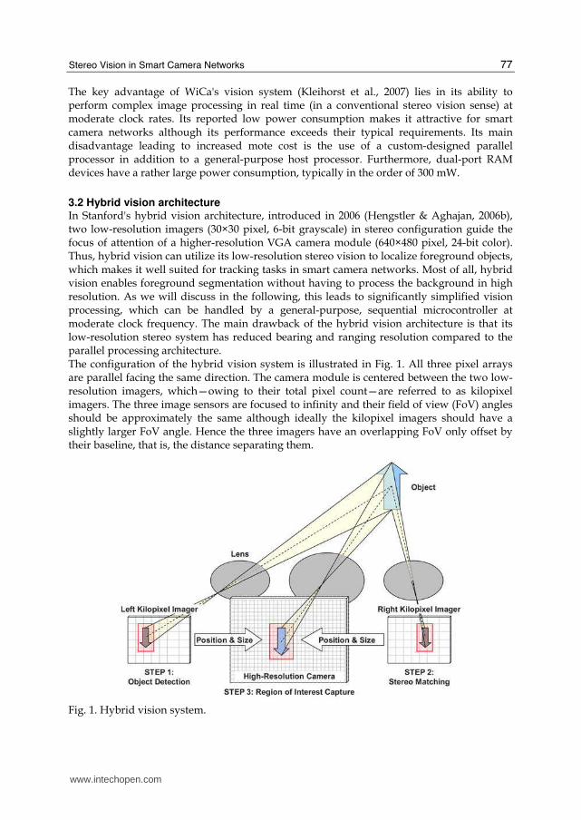
3.2 Hybrid vision architecture In Stanford's hybrid vision architecture, introduced in 2006 (Hengstler & Aghajan, 2006b), two low-resolution imagers (30×30 pixel, 6-bit grayscale) in stereo configuration guide the focus of attention of a higher-resolution VGA camera module (640×480 pixel, 24-bit color). Thus, hybrid vision can utilize its low-resolution stereo vision to localize foreground objects, which makes it well suited for tracking tasks in smart camera networks. Most of all, hybrid vision enables foreground segmentation without having to process the background in high resolution. As we will discuss in the following, this leads to significantly simplified vision processing, which can be handled by a general-purpose, sequential microcontroller at moderate clock frequency. The main drawback of the hybrid vision architecture is that its low-resolution stereo system has reduced bearing and ranging resolution compared to the parallel processing architecture. The configuration of the hybrid vision system is illustrated in Fig. 1. All three pixel arrays are parallel facing the same direction. The camera module is centered between the two low-resolution imagers, which—owing to their total pixel count—are referred to as kilopixel imagers. The three image sensors are focused to infinity and their field of view (FoV) angles should be approximately the same although ideally the kilopixel imagers should have a slightly larger FoV angle. Hence the three imagers have an overlapping FoV only offset by their baseline, that is, the distance separating them.
Fig. 1. Hybrid vision system.
www.intechopen.com

Stereo Vision
78
In the simplest operation of the hybrid vision system, one of the kilopixel imagers is used to continuously poll for moving objects entering its FoV. Once one or possibly more objects have been detected, position and size within a kilopixel image can be determined for each object. Stereo vision of the two kilopixel imagers yields bearing and distance to the object. This information allows us to calculate the region of interest (RoI) containing the object within the VGA camera's image plane. Subsequently, the microcontroller triggers the VGA camera module to capture a high-resolution grayscale or color RoI including only the detected object. After optional additional low-level processing, the object's RoI will then be handed over to intermediate-level processing functions.
4. Hybrid vision algorithms
The image processing algorithms behind the hybrid vision system, which were first described in (Hengstler et al., 2007), are designed to detect and localize objects entering its FoV. Since a generic 32-bit RISC architecture without dedicated DSP engines needs to execute these algorithms, they are intentionally kept at low computational complexity. The overall vision processing flow is shown in the flowchart of Fig. 2. Both low-resolution (LR) imagers continue updating their background image and estimate of temporal pixel noise when no objects are present. Upon detection of a moving object in the left kilopixel image, the vision system determines the bounding box and stores the object's RoI. This RoI serves as a template to locate the object's position within the FoV of the right kilopixel imager. If this stereo matching cannot establish a positive match to the template, the left LR imager will continue polling for moving objects. This case occurs for example when the object lies outside the overlapping FoV of the two kilopixel imagers. Knowing the object's position within both LR image arrays and its size, the vision system triggers the VGA camera module to acquire a high-resolution (HR) snapshot of the object. The left kilopixel imager can continue tracking the object until it leaves its FoV and initiate additional HR RoI acquisitions of the object as required by the application. Note that the following discussion is limited to one object inside the FoV, but it can be easily extended to multiple foreground objects.
Fig. 2. Flowchart of the vision processing algorithm.
www.intechopen.com
Stereo Vision in Smart Camera Networks
79
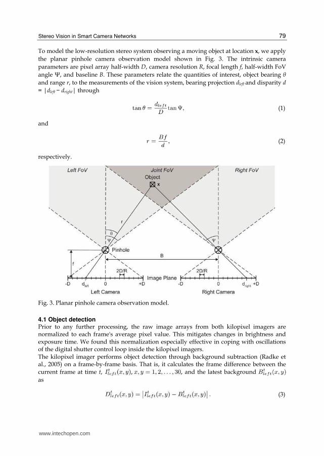
To model the low-resolution stereo system observing a moving object at location x, we apply
the planar pinhole camera observation model shown in Fig. 3. The intrinsic camera
parameters are pixel array half-width D, camera resolution R, focal length f, half-width FoV
angle Ψ, and baseline B. These parameters relate the quantities of interest, object bearing θ and range r, to the measurements of the vision system, bearing projection dleft and disparity d
= |dleft − dright| through
(1)
and
(2)
respectively.
Fig. 3. Planar pinhole camera observation model.
4.1 Object detection Prior to any further processing, the raw image arrays from both kilopixel imagers are normalized to each frame's average pixel value. This mitigates changes in brightness and exposure time. We found this normalization especially effective in coping with oscillations of the digital shutter control loop inside the kilopixel imagers. The kilopixel imager performs object detection through background subtraction (Radke et al., 2005) on a frame-by-frame basis. That is, it calculates the frame difference between the
current frame at time t, and the latest background
as
(3)
www.intechopen.com
Stereo Vision
80
All pixels, whose frame difference exceed a preset multiple k of the temporal
noise standard deviation σn, are set in a binary motion mask as potential
candidates of motion,
(4)
In MeshEye's vision system, σn is estimated on background frames and it typically ranges
around 1.75; k is set to around 6. To eliminate objects smaller than 2×2 pixel, we low-pass
filter the binary motion mask according to
(5)
where conv2 denotes two-dimensional convolution.
In the final processing step of object detection, a blob search algorithm identifies all regions
as moving objects, which consist of four-connected groups of unity pixels within the binary
mask that contain at least one unity pixel of the filtered mask It is
then straightforward to determine the bounding box of each object through extraction of the
object's difference RoI as a subset of the current frame difference .
The object's bearing projection follows as the mean of the object's intensity distribution,
which is projected onto the horizontal axis of the pixel array.
4.2 Stereo matching The objective of the stereo matching algorithm lies in locating the object's RoI within the
right kilopixel image array. Since the pixel arrays of both LR imagers are aligned in parallel,
the object will appear as a shifted version in the right kilopixel array if it is located within
their joint FoV. This satisfies the requirements for template matching based on cross-
correlation. Therefore, the vision system computes the cross-correlation of the object's array
along the epipolar lines (for an introduction to epipolar geometry, refer to
(Foresti et al., 2005) for example) of the right kilopixel difference array ,
(6)
where xcor2 denotes two-dimensional unbiased cross-correlation without boundary padding
such that u, v = 1, 2, . . . , 30.
Lastly, the (u, v) coordinate with the largest cross-correlation value—or the average (u, v)
coordinate in case of multiple largest cross-correlation values—is assumed as the object's
position within the right LR image array. However, to qualify a positive match and remove
objects outside the joint FoV, the maximum cross-correlation value has to be sufficiently
close to the center autocorrelation value of the object's RoI, which may be expressed as
(7)
denotes the unbiased autocorrelation of the object's difference array
www.intechopen.com

Stereo Vision in Smart Camera Networks
81
(8)
If this condition is not met, no positive match can be established and the object is discarded.
Otherwise, the object's bearing projection t
rightd is computed as the horizontal value of the
mean of the object's cross-correlation distribution
4.3 Object acquisition The hybrid vision system can finally determine the object's position within the HR pixel array using the object's extent and positions and within the LR arrays. With this
information, a high-resolution snapshot containing only the moving object can be efficiently acquired by using the camera's built-in windowing function. As mentioned before, the HR background is not analyzed and not even acquired with the hybrid vision system. The HR snapshot of the object is stored for further processing or exchange with neighboring smart cameras. Such processing can include object classification or even distributed, multi-camera view identification based on its shape, orientation, aspect ratio, or color histogram for instance. Two examples captured with Stanford's MeshEye smart camera mote are shown in Fig. 4. It contains an indoor (Fig. 4a) and an outdoor (Fig. 4b) snapshot of a moving person. Notice that the LR views have a non-ideal smaller FoV than the HR view.
(a) Indoor Snapshot (b) Outdoor Snapshot
Fig. 4. Hybrid vision system performing person localization: indoor (a) and outdoor (b) snapshots. Bounding boxes mark the person's locations in the LR and HR views.
4.4 Computational efficiency To conclude this section, let us consider the computational savings that the hybrid vision system achieves over the WiCa smart camera mote. WiCa's dual high-resolution camera system combined with the IC3D SIMD dedicated image processor establishes a fair basis of comparison among published embedded stereo vision systems to carry out moving object localization and RoI extraction.
www.intechopen.com

Stereo Vision
82
For simplicity, this consideration of computational efficiency is limited to one moving object within the vision system's FoV. The MeshEye vision system carries out the algorithms described in the previous subsections. For the dual-camera SIMD system, our calculation assumes that it performs the same computations on its two HR cameras rather than two LR imagers, which result in a moving object's pixel array and estimated bearing and range. Whenever possible, the computations utilize IC3D's line-parallel processor architecture, which executes an instruction across an entire line of pixel data within one instruction cycle. Of course, an alternative approach would be to downsize incoming frames from VGA to kilopixel resolution prior to object detection and extraction. This however would underutilize the line-parallel processor and not take full advantage of its 640-pixel wide line buffers. The computational efficiency of MeshEye's vision system relative to the WiCA vision system is shown in Fig. 5. More specifically, it graphs the ratio of number of computations of the dual-camera SIMD system over the hybrid vision system as a function of object size in high resolution when both systems perform object detection, localization and RoI extraction. Hybrid vision achieves a fivefold reduction in the number of computations for small object sizes, but the gains in efficiency diminish down to 0.7 as object sizes increase. Smaller objects require fewer computations and hence hybrid-resolution processing outperforms the parallel processing system. Large objects cause a heavier processing load and hence the SIMD processor excels over hybrid vision. For objects sized around 132,800 high-resolution pixel2, which amounts to rather large objects of for example 364×364 pixel—or about 40% of the VGA frame, both vision systems have equal computational efficiency. Note that it is for these significant reductions in the number of computations for moderately sized objects that makes hybrid vision well suited for smart camera embedded vision without the need for a dedicated, high-performance DSP engine.
Fig. 5. Computational efficiency of the hybrid vision system over the dual-camera SIMD system.
www.intechopen.com

Stereo Vision in Smart Camera Networks
83
5. Hybrid vision implementation
This section briefly describes the architecture of Stanford's MeshEyeTM mote as a hardware implementation of the hybrid vision system. Its design targets the provision of sufficient processing power for hybrid vision while minimizing component count and power consumption.
5.1 Hardware architecture The block-level architecture of the MeshEye smart camera mote is shown in Fig. 6. The architecture is centered around an Atmel AT91SAM7S family microcontroller (Atmel, 2006), which contains up to 256 KBytes of flash memory and 64 KBytes of SRAM. Its leading power-efficient ARM7TDMI architecture can be clocked up to 55 MHz. The mote features a USB 2.0 full-speed port and a serial interface for wired connection. Furthermore, the mote can host up to eight kilopixel imagers and one VGA camera module, for which we chose Agilent Technologies' ADNS-3060 high-performance optical mouse sensor (Agilent, 2004) (30×30 pixel, 6-bit grayscale) and Agilent Technologies' ADCM-2700 landscape VGA resolution CMOS camera module (Agilent, 2005) (640×480 pixel programmable, grayscale or 24-bit color), respectively. An MMC/SD flash memory card provides sufficient and scalable non-volatile memory for temporary frame buffering or even image archival. Wireless connection to other motes in the network can be established through a Texas Instruments CC2420 2.4 GHz IEEE 802.15.4/ZigBee-ready RF transceiver (Texas, 2006), which supports data transmission at 250 Kbits per second according to the IEEE 802.15.4 standard with a maximum transmit power of 1 mW in the unlicensed 2.4 GHz ISM band. The mote can either be powered by a stationary power supply if available or battery-operated for mobile applications or ease of deployment.
Fig. 6. Block diagram of the MeshEyeTM architecture.
The objectives guiding the electrical design of the MeshEye architecture have been the integration of low-power, COTS components, use of standard interfaces, and most of all minimization of total component count. The main motivation in keeping the component
www.intechopen.com

Stereo Vision
84
count small lies in reduced power consumption and mote cost. The use of standard interfaces manifests itself in that a single SPI interface connects flash memory card, kilopixel imagers, and radio to the microcontroller. A TWI interface controls the camera module while its CCIR video is read out through general-purpose I/O pins. Note that this CCIR read-out method is not common but avoids additional interface components at the expense of a reduced frame rate of about 3 frames per second. Most other solutions interface CCIR image sensors to microcontrollers through a combination of an FPGA or CPLD and static memory for frame buffering. While such solutions may enable video streaming, they oftentimes add significantly to mote cost and the power budget. Fig. 7 pictures the first prototype of the MeshEye smart camera mote. It consists of a base board and a sensor board. The base board hosts the voltage regulators, microcontroller, radio, MMC/SD flash card (not visible) and external interface connectors. Power can be supplied through an external source, the Mini-USB port, or pairs of AA batteries. The sensor board, which sits on top of the base board, contains two kilopixel imagers, the VGA camera module, and two white LEDs for short-range illumination.
Fig. 7. Photograph of the first MeshEyeTM smart camera mote.
The kilopixel imagers use plastic aspheric lenses with a 4.6 mm focal length f and have a 57 mm baseline B. This allows for a maximum perceived depth of 8.74 m in theory, which we deem adequate for indoor and limited outdoor usage. At fixed resolution of the image sensors, one may increase the focal length to increase the depth limit at the expense of narrower FoV angles.
5.2 Power model An important performance metric for battery-operated motes is their lifetime during deployment. For this reason, generating a power model for the MeshEye smart camera mote is a crucial step in analyzing its energy consumption and predicting its lifetime during object localization operation.
www.intechopen.com
Stereo Vision in Smart Camera Networks
85
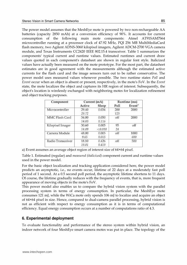
The power model assumes that the MeshEye mote is powered by two non-rechargeable AA batteries (capacity 2850 mAh) at a conversion efficiency of 90%. It accounts for current consumption of the following main mote components: Atmel AT91SAM7S64 microcontroller running at a processor clock of 47.92 MHz, PQI 256 MB MultiMediaCard flash memory, two Agilent ADNS-3060 kilopixel imagers, Agilent ADCM-2700 VGA camera module, and Texas Instruments CC2420 IEEE 802.15.4 transceiver. Table 1 summarizes the components' typical current and runtime values. Estimated runtimes and current draw values quoted in each component's datasheet are shown in regular font style. Italicized values have actually been measured on the mote prototype. For the most part, the datasheet estimates are in good agreement with the measurements although the estimated active currents for the flash card and the image sensors turn out to be rather conservative. The power model uses measured values whenever possible. The two runtime states Poll and Event occur when an object is absent or present, respectively, in the mote's FoV. In the Event state, the mote localizes the object and captures its HR region of interest. Subsequently, the object's location is wirelessly exchanged with neighboring motes for localization refinement and object tracking purposes.
a) Event assumes an average object region of interest size of 64×64 pixel.
Table 1. Estimated (regular) and measured (italicized) component current and runtime values used in the power model.
For the basic object localization and tracking application considered here, the power model predicts an asymptotic, i.e., no events occur, lifetime of 22 days at a moderately fast poll period of 1 second. At a 0.5 second poll period, the asymptotic lifetime shortens to 11 days. Of course, the lifetime gradually reduces with the frequency of events, that is, more frequent appearance of moving objects in the mote's FoV. This power model also enables us to compare the hybrid vision system with the parallel processing system in terms of energy consumption. In particular, the MeshEye mote consumes 121 mJ, while the WiCa mote only spends 106 mJ to localize and acquire an object of 64×64 pixel in size. Hence, compared to dual-camera parallel processing, hybrid vision is not as efficient with respect to energy consumption as it is in terms of computational efficiency. Equal energy consumption occurs at a number of computations ratio of 4.3.
6. Experimental deployment
To evaluate functionality and performance of the stereo system within hybrid vision, an
indoor network of four MeshEye smart camera motes was put in place. The topology of the
www.intechopen.com

Stereo Vision
86
network is shown in Fig. 8: the four motes are located on the corners of a rectangle with
their camera axes oriented towards the rectangle's center. Each mote records the kilopixel
images to an MMC flash memory card at 10 fps over a one minute duration. During this
time, a person follows the ground truth path drawn in Fig. 8, which was marked on the
room's floor as an inner and outer rectangle. More specifically, the target first walks twice
along the inner and then twice along the outer rectangle.
Fig. 8. Topology and observations of experimental network deployment.
The recorded image sequences were then post-processed with the hybrid vision algorithms
to determine each mote's target localization over time. These location observations are
overlaid onto the network topology in Fig. 8 using different markers. The associated
measurements of target bearing angle and range are shown in the two plots to the right. In
the final step, a sequential Bayesian tracking algorithm (Hengstler & Aghajan, 2007) fuses
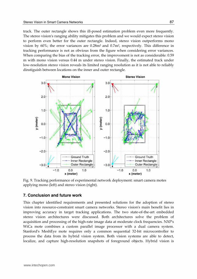
the individual location observations to reconstruct the target's track. Fig. 9 shows the
resulting track when the motes apply either monocular or stereo vision. Under mono vision,
the smart camera motes utilize only the left of the two kilopixel imagers. Note that the
target's track is drawn separately for the inner and outer rectangle.
For evaluation purposes, we computed the variance of the tracking error, which is the
difference between estimated and ground truth location, as a metric of tracking
performance. For the inner rectangle, mono vision achieves an error variance of 0.16 m2 and
stereo vision a variance of 0.11 m2—a 30% improvement. Generally speaking, mono vision
exhibits high localization uncertainty when the axes of the observing cameras are close to
parallel. Obviously, this occurs primarily in proximity to the corners of the rectangular
www.intechopen.com
Stereo Vision in Smart Camera Networks
87
track. The outer rectangle shows this ill-posed estimation problem even more frequently.
The stereo vision's ranging ability mitigates this problem and we would expect stereo vision
to perform even better for the outer rectangle. Indeed, stereo vision outperforms mono
vision by 60%; the error variances are 0.28m2 and 0.7m2, respectively. This difference in
tracking performance is not as obvious from the figure when considering error variances.
When comparing the bias of the tracking error, the improvement is not as considerable: 0.59
m with mono vision versus 0.44 m under stereo vision. Finally, the estimated track under
low-resolution stereo vision reveals its limited ranging resolution as it is not able to reliably
dinstiguish between locations on the inner and outer rectangle.
Fig. 9. Tracking performance of experimental network deployment: smart camera motes applying mono (left) and stereo vision (right).
7. Conclusion and future work
This chapter identified requirements and presented solutions for the adoption of stereo
vision into resource-constraint smart camera networks. Stereo vision's main benefit lies in
improving accuracy in target tracking applications. The two state-of-the-art embedded
stereo vision architectures were discussed. Both architectures solve the problem of
acquisition and processing of the high-rate image data at moderate clock frequencies. NXP's
WiCa mote combines a custom parallel image processor with a dual camera system.
Stanford's MeshEye mote requires only a common sequential 32-bit microcontroller to
process the data from its hybrid vision system. Both vision systems are able to detect,
localize, and capture high-resolution snapshots of foreground objects. Hybrid vision is
www.intechopen.com

Stereo Vision
88
computationally more efficient and consumes less energy for smaller objects within its field
of view. This makes it well suited for a variety of applications in smart camera networks
despite its low-resolution ranging capability. The experimental network deployment of four
MeshEye motes resulted in a 30% reduction in target tracking error over smart camera
motes utilizing solely monocular vision.
The availability of embedded stereo vision motes is the necessary step in their adoption for
applications in smart camera networks. While this chapter covered their vision processing
and hardware implementation, the challenge of vision calibration has not been addressed.
Variations in the optical system and in alignment of the image sensors cause systematic
errors in object localization. Calibration techniques, which can be easily and cheaply
accomplished in volume production, need to be developed to measure and compensate
these variations.
In conclusion, we expect to see more research contributions in the near future that analyze
the performance of stereo vision in distributed camera networks with more rigor. This
includes studying their merit over mono vision for different network tasks with respect to
tracking accuracy, network lifetime, cost of deployment, and number of required camera
motes. (Hengstler & Aghajan, 2007), for example, presents an early study of performance
trade-offs for target tracking between mono and stereo vision in smart camera networks. Its
simulation results encouragingly indicate that (i) stereo vision outperforms mono vision by
factors of 2 to 5 in tracking accuracy and (ii) doubling the camera resolution can result in one
third the tracking error variance.
8. References
Agilent Technologies (2004). ADNS-3060 High-Performance Optical Mouse Sensor,
Datasheet, Oct. 2004
Agilent Technologies (2005). ADCM-2700-0000 Landscape VGA Resolution CMOS Camera
Module, Datasheet, Jan. 2005
Atmel Corporation (2006). AT91SAM7Sxxx AT91 ARM Thumb-based Microcontrollers,
Datasheet, Apr. 2006
Bramberger, M.; Doblander, A.; Maier, A.; Rinner, B. & Schwabach, H. (2006). Distributed
embedded smart cameras for surveillance applications, IEEE Computer Processing
Magazine, Vol. 39, No. 2, Feb. 2006, pp. 68-75
Foresti, G.; Micheloni, C.; Snidaro, L.; Remagnino, P. & Ellis, T. (2005). Active video-based
surveillance system: the low-level image and video processing techniques needed
for implementation, IEEE Signal Processing Magazine, Vol. 22, No. 2, Mar. 2005, pp.
25-37
Hampapur, A.; Brown, L.; Connell, J.; Ekin, A.; Haas, N.; Lu, M.; Merkl, H. & Pankanti, S.
(2005). Smart video surveillance: exploring the concept of multiscale
spatiotemporal tracking, IEEE Signal Processing Magazine, Vol. 22, No. 2, Mar. 2005,
pp. 38-51
Hengstler, S. & Aghajan, H. (2006a). Application Development in Vision-Enabled Wireless
Sensor Networks, Proceedings of the International Conference on Systems and Networks
Communications (ICSNC 2006), pp. 30-36, Oct. 2006, IEEE Computer Society,
Washington, DC, USA
www.intechopen.com

Stereo Vision in Smart Camera Networks
89
Hengstler, S. & Aghajan, H. (2006b). A Smart Camera Mote Architecture for Distributed
Intelligent Surveillance, ACM SenSys 2006 International Workshop on Distributed
Smart Cameras (DSC 2006), pp. 6-10, Oct. 2006, ACM, New York, NY, USA
Hengstler, S. & Aghajan, H. (2007). Application-Oriented Design of Smart Camera
Networks, Proceedings of the First ACM/IEEE International Conference on Distributed
Smart Cameras (ICDSC '07), pp. 12-19, Sept. 2007, ACM Press, New York, NY,
USA
Hengstler, S.; Prashanth, D.; Fong, S. & Aghajan, H. (2007). MeshEye: a hybrid-
resolution smart camera mote for applications in distributed intelligent
surveillance, Proceedings of the 6th International Conference on Information
Processing in Sensor Networks (IPSN '07), pp. 360-369, Apr. 2007, ACM Press,
New York, NY, USA
Kleihorst, R.; Abbo, A.; Choudhary, V. & Schueler, B. (2006). Design Challenges for Power
Consumption in Mobile Smart Cameras, Proceedings of COGnitive systems with
Interactive Sensors (COGIS 2006), pp. 9B-3, Mar. 2006, S.E.E., Paris, France
Kleihorst, R.; Schueler, B. & Danilin, A. (2007). Architecture and Applications of
Wireless Smart Cameras (Networks), Proceedings of the 2007 IEEE International
Conference on Acoustics, Speech, and Signal Processing (ICASSP '07), Vol. 4, pp.
1373-1376, Apr. 2007, IEEE Signal Processing Society, Piscataway, New Jersey,
USA
Liu, Y. & Das, S. (2006). Information-intensive wireless sensor networks: potential and
challenges, IEEE Communications Magazine, Vol. 44, No. 11, Nov. 2006, pp. 142-
147
Maleki-Tabar, A.; Keshavarz, A. & Aghajan, H. (2006). Smart Home Care Network using
Sensor Fusion and Distributed Vision-Based Reasoning, Proceedings of the 4th ACM
International Workshop on Video Surveillance and Sensor Networks (VSSN 2006), pp.
145-154, Oct. 2006, ACM, New York, NY, USA
Nakamura, E.; Loureiro, A. & Frery, A. (2007). Information fusion for wireless sensor
networks: Methods, models, and classifications, ACM Computing Surveys (CSUR),
Vol. 39, No. 3, Aug. 2007, pp. 9
Qureshi, F. & Terzopoulos, D. (2007). Smart Camera Networks in Virtual Reality, Proceedings
of the First ACM/IEEE International Conference on Distributed Smart Cameras (ICDSC
'07), pp. 87-94, Sept. 2007, ACM Press, New York, NY, USA
Radke, R.; Andra, S.; Al-Kofahi, O. & Roysam, B. (2005). Image change detection algorithms:
a systematic survey, IEEE Transactions on Image Processing, Vol. 14, No. 3, Mar. 2005,
pp. 294-307
Rahimi, M.; Ahmadian, S.; Zats, D.; Laufer, R. & Estrin, D. (2006). Magic of Numbers in
Networks of Wireless Image Sensors, ACM SenSys 2006 International Workshop on
Distributed Smart Cameras (DSC 2006), Vol. 1, pp. 77-81, Oct. 2006, ACM, New York,
NY, USA
Rahimi, M.; Baer, R.; Iroezi, O.; Garcia, J.; Warrior, J.; Estrin, D. & Srivastava, M. (2005).
Cyclops: in situ image sensing and interpretation in wireless sensor networks,
Proceedings of the 3rd International Conference on Embedded Networked Sensor Systems
(SenSys '05), pp. 192-204, Nov. 2005, ACM, New York, NY, USA
www.intechopen.com

Stereo Vision
90
Texas Instruments (2006). Chipcon CC2420 2.4 GHz IEEE 802.15.4/ZigBee-ready RF
Transceiver, Datasheet, 2006
Zhao, F. & Guibas, L. (2004). Wireless Sensor Networks: An Information Processing Approach,
Morgan Kaufmann Publishers Inc., San Francisco, CA, USA
www.intechopen.com

Stereo VisionEdited by Asim Bhatti
ISBN 978-953-7619-22-0Hard cover, 372 pagesPublisher InTechPublished online 01, November, 2008Published in print edition November, 2008
InTech EuropeUniversity Campus STeP Ri Slavka Krautzeka 83/A 51000 Rijeka, Croatia Phone: +385 (51) 770 447 Fax: +385 (51) 686 166www.intechopen.com
InTech ChinaUnit 405, Office Block, Hotel Equatorial Shanghai No.65, Yan An Road (West), Shanghai, 200040, China
Phone: +86-21-62489820 Fax: +86-21-62489821
The book comprehensively covers almost all aspects of stereo vision. In addition reader can find topics fromdefining knowledge gaps to the state of the art algorithms as well as current application trends of stereo visionto the development of intelligent hardware modules and smart cameras. It would not be an exaggeration if thisbook is considered to be one of the most comprehensive books published in reference to the current researchin the field of stereo vision. Research topics covered in this book makes it equally essential and important forstudents and early career researchers as well as senior academics linked with computer vision.
How to referenceIn order to correctly reference this scholarly work, feel free to copy and paste the following:
Stephan Hengstler (2008). Stereo Vision in Smart Camera Networks, Stereo Vision, Asim Bhatti (Ed.), ISBN:978-953-7619-22-0, InTech, Available from:http://www.intechopen.com/books/stereo_vision/stereo_vision_in_smart_camera_networks

© 2008 The Author(s). Licensee IntechOpen. This chapter is distributedunder the terms of the Creative Commons Attribution-NonCommercial-ShareAlike-3.0 License, which permits use, distribution and reproduction fornon-commercial purposes, provided the original is properly cited andderivative works building on this content are distributed under the samelicense.